summary of 03/03/2010 meeting between nrc and plastics
TRANSCRIPT

Meeting Summary Meeting between NRC and Plastics Pipe Institute Representative
March 3, 2010 Rockville, MD
Purpose:
The purpose of the meeting was to facilitate communication between the NRC staff unable to attend the recent public ASME Code meeting and a representative of the plastic piping industry. Mr. Stephen Boros of the Plastics Pipe Institute (PPI) presented the same brief made at the recent public ASME Boiler and Pressure Vessel Code Week meeting entitled, “Long-Term Hydrostatic Strength and Design of Polyethylene Piping Compounds.”
Meeting Summary:
NRC is reviewing Code Case N-755 on the use of high-density polyethylene (HDPE) piping in safety-related nuclear applications. NRC requested the meeting and presentation with Mr. Stephen Boros of PPI to clarify the methods used to establish the design stress values in N-755. Mr. Boros is the Technical Director of PPI and chairs the Hydrostatic Stress Board. The Hydrostatic Stress Board is responsible for providing pressure ratings (i.e. the hydrostatic design basis or HDB) for plastic pipe resins based on proprietary test data submitted by resin manufacturers. The HDB helps establish the allowable stress values for plastic pipe design. Mr. Boros presented the attached brief, which was the same material as presented at the public February 2010 ASME Boiler and Pressure Vessel Code Meeting. He presented the methodology to establish the HDB based on standardized test methods. He further discussed the determination of the hydrostatic design stress (HDS) used to develop design stress values for HDPE resins. Mr. Boros also provided a status of PPI sponsored research to update generic fusion procedures. The ASME HDPE Fusion Task Group will provide updates of the results of the fusion research at future ASME Code meetings.
Meeting Attendees:
Attendees Affiliation Eric Focht NRC/RES/DE/CIB Tim Lupold NRC/NRR/DCI/CPNB Chakrapani Basavaraju NRC/NRR/DE/EMCB Don Naujock NRC/NRR/DE/CPNB Robert Hsu NRC/NRO/DE/EMB John Wu NRC/NRO/DE/EMB Eric Reichelt NRC/NRO/DE/CIB1 David Terao NRC/NRO/DE/CIB1 Aladar Csontos NRC/RES/DE/CIB Prabhat Krishnaswamy Engineering Mechanics Corp. of Columbus Steven Boros Plastics Pipe Institute

3/15/2010
1
ASME BPV CommitteePE Pipe Symposium
February 2010
Long-Term Hydrostatic Strength and Design of Polyethylene Piping
Compounds
Member Run, Member Led!
Stephen J. BorosTechnical Director – Plastics Pipe Institute
Chairman, Hydrostatic Stress Board
ASME BPV CommitteePE Pipe Symposium
February 2010
Overview
Long-Term Hydrostatic Strength (LTHS)Regression AnalysisEstablishing a Hydrostatic Design Basis (HDB)Design Factor (i.e. Service Factor)
Member Run, Member Led!
Maximum Design Pressure – HDSNew applications

3/15/2010
2
ASME BPV CommitteePE Pipe Symposium
February 2010
Long-Term Hydrostatic Strength
Member Run, Member Led!
ASME BPV CommitteePE Pipe Symposium
February 2010
Long-Term Hydrostatic Strength
Viscoelastic Response to Stressp– Dependent on level and duration of stress– Unlike metals, long-term strength cannot be
determined from short-term tensile test.
Member Run, Member Led!
3/15/2010
3
ASME BPV CommitteePE Pipe Symposium
February 2010
Long-Term Hydrostatic Strength
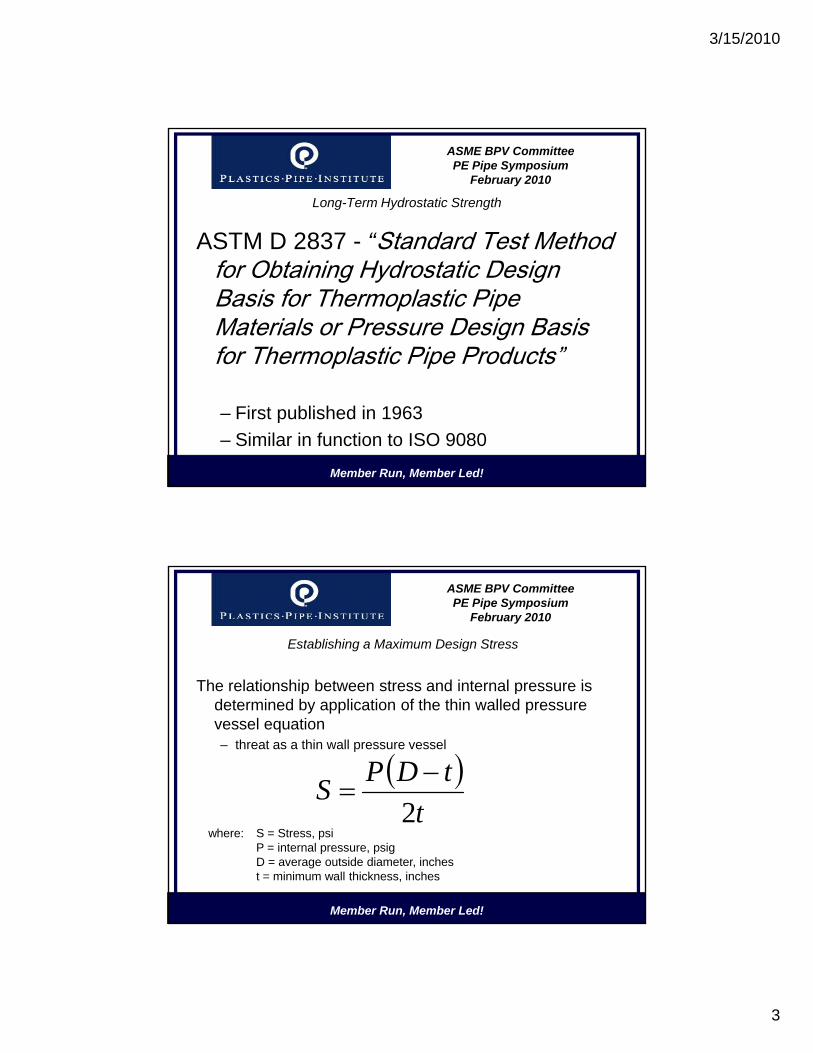
ASTM D 2837 - “Standard Test MethodASTM D 2837 Standard Test Method for Obtaining Hydrostatic Design Basis for Thermoplastic Pipe Materials or Pressure Design Basis for Thermoplastic Pipe Products”
Member Run, Member Led!
p p
– First published in 1963– Similar in function to ISO 9080
ASME BPV CommitteePE Pipe Symposium
February 2010
Establishing a Maximum Design Stress
The relationship between stress and internal pressure isThe relationship between stress and internal pressure is determined by application of the thin walled pressure vessel equation– threat as a thin wall pressure vessel
( )tDPS2−
=
Member Run, Member Led!
where: S = Stress, psiP = internal pressure, psigD = average outside diameter, inchest = minimum wall thickness, inches
t2

3/15/2010
4
ASME BPV CommitteePE Pipe Symposium
February 2010
Long-Term Hydrostatic Strength
Member Run, Member Led!
ASME BPV CommitteePE Pipe Symposium
February 2010
Regression Analysis
Li L t S M d l l /lLinear Least Squares Model – log/log.
h = a + bf
where: h = logarithm of failure time, hoursf = logarithm of failure stress, psi
Member Run, Member Led!

3/15/2010
5
ASME BPV CommitteePE Pipe Symposium
February 2010
Regression Analysis
Member Run, Member Led!
ASME BPV CommitteePE Pipe Symposium
February 2010
Long-Term Hydrostatic Strength
Long-term strength is categorized, or standardized, within established ranges called a Hydrostatic Design Basis.
Range of Calculated LTHS ValuesHydrostatic Design
Basispsi (MPa) psi (MPA)760 to < 960 (5.24 to < 6.62) 800 (5.52)960 to < 1200 (6.62 to 8.274) 1000 (6.89)1200 to < 1530 (8.27 to < 10.55) 1250 (8.62)
Member Run, Member Led!
1530 to < 1920 (10.55 to < 13.24) 1600 (11.03)1920 to < 2400 (13.24 to <16.55) 2000 (13.79)2400 to < 3020 (16.55 to <20.82) 2500 (17.24)3020 to < 3830 (20.82 to < 26.41) 3150 (21.72)3830 to < 4800 (26.41 to < 33.09) 4000 (27.58)

3/15/2010
6
ASME BPV CommitteePE Pipe Symposium
February 2010
Regression Analysis
To assure linearity of extrapolation:
• Validation – assure linearity of extrapolation to 100,000 hours.S b t ti ti
Member Run, Member Led!
• Substantiation – assures linearity to 50 years.
ASME BPV CommitteePE Pipe Symposium
February 2010
Typical PE 4710 Regression Analysis
Follow PPI TR-3 Policies for establishing a hydrostatic Design Basis:
• One 73°F and 140°F full dataset to 10,000 hours meeting the full requirements of D 2837.
• Minimum 18 data points with proper distribution.
Member Run, Member Led!
• LTHS minimum for HDB.• LCL/LTHS ratio > 0.90• LTHS50 > 80% LTHS.

3/15/2010
7
ASME BPV CommitteePE Pipe Symposium
February 2010
Typical PE 4710 Regression Analysis
Follow PPI TR-3 Policies for establishing a Hydrostatic Design Basis - HDB:
• Two additional 73°F and 140°Fdatasets to 2000 hours.
• 10 data points minimum with proper distribution.
• Distinct and separate lots of the compound to d t t i t
Member Run, Member Led!
demonstrate consistency.
• The regression analysis must also meet the ASTM D 2837 requirements (HDB, LCL, etc…).
ASME BPV CommitteePE Pipe Symposium
February 2010
Typical PE 4710 Regression Analysis
Follow PPI TR-3 Policies for establishing a Hydrostatic Design Basis – HDB:
• Validation of 73°F and 140°F HDB – two datasets at 80C or 90C.
• Substantiation of the 73°F HDB -
80C 6000 hrs
Member Run, Member Led!
80C – 6000 hrs
90C – 2400 hrs

3/15/2010
8
ASME BPV CommitteePE Pipe Symposium
February 2010
Validation of the 140°F HDB
HDB to be Validated (psi)
Test Temperature
193°F (90°C) 176°F (80°C)
Stress (psi)
Time (h) Stress (psi) Time (h)
1250 860 3800 970 11300
1000 690 “ 775 “
Member Run, Member Led!
800 550 “ 620 “
630 435 “ 490 “
500 345 “ 390 “

3/15/2010
9
ASME BPV CommitteePE Pipe Symposium
February 2010
Establishing a Maximum Design Stress
Maximum design stress requires the application of a design factor (DF) -while similar, not the same as a safety factor, or margin of safety.
HDS = HDB x DF x DFT
Member Run, Member Led!
Where: HDS = hydrostatic design stress, psiHDB = hydrostatic design basis, psiDF = design factor, a number less than one.
HDS HDB x DF x DFT
ASME BPV CommitteePE Pipe Symposium
February 2010
Establishing a Maximum Design Stress
• Choice of DF is based on several factors– Method used to establish long-term strength– Failure mechanisms– Reaction to stress intensifications (fracture
h i )
Member Run, Member Led!
mechanics)– Installation practices– Range of “normal” operating conditions

3/15/2010
10
ASME BPV CommitteePE Pipe Symposium
February 2010
Establishing a Maximum Design Stress
In 1963 a design factor (DF) of 0 5 was “chosen” toIn 1963 a design factor (DF) of 0.5 was chosen to provide an appropriately conservative design.– Purposely chosen as a multiplier to be different from a safety
factor.– Excellent performance over last 40 years.– Continuous development of newer materials has led to revisiting
this factor
Member Run, Member Led!
this factor.
Not equivalent to a 2.0 safety factor
ASME BPV CommitteePE Pipe Symposium
February 2010
Establishing a Maximum Design Stress
Older PE materials had stress regression curves showing t iti t “b ittl ” t f iltransition to “brittle” type failures.
Member Run, Member Led!

3/15/2010
11
ASME BPV CommitteePE Pipe Symposium
February 2010
Establishing a Maximum Design Stress
The Hydrostatic Stress Board of PPI set additionalThe Hydrostatic Stress Board of PPI set additional performance criteria for PE materials
These materials could be operated at a higher bulk stress without sacrificing service life or safety.
1) 50 year substantiation
Member Run, Member Led!
2) 90% LCL/LTHS ratio
3) 500 hours PENT SCG performance
ASME BPV CommitteePE Pipe Symposium
February 2010
Establishing a Maximum Design Stress
1) 50 year Substantiation
– Ductile mode through at least the 50-year intercept.
Member Run, Member Led!
– PE material continues to operate in the ductile state

3/15/2010
12
ASME BPV CommitteePE Pipe Symposium
February 2010
Establishing a Maximum Design Stress
2) 90% LCL/LTHS ratio
– Ratio of average LTHS to 95% LCL
Member Run, Member Led!
– Ensures higher statistical reliability in strength forecast.
ASME BPV CommitteePE Pipe Symposium
February 2010
Establishing a Maximum Design Stress
3) 500 hours PENT SCG performance
– ASTM F 1473 slow crack growth resistance indication
Member Run, Member Led!
– Essential immunity to effects of localized stress intensifications.

3/15/2010
13
ASME BPV CommitteePE Pipe Symposium
February 2010
Establishing a Maximum Design Stress
PE materials meeting the high performance criteriag g p
Member Run, Member Led!
ASME BPV CommitteePE Pipe Symposium
February 2010
Establishing a Maximum Design Stress
This means a 25% higher design stress from internal pressureg g p
Member Run, Member Led!

3/15/2010
14
ASME BPV CommitteePE Pipe Symposium
February 2010
Establishing a Maximum Design Stress
This leads to the question, “Is this simply a reduction in the safety factor?”
Member Run, Member Led!
Answer: No!!
ASME BPV CommitteePE Pipe Symposium
February 2010
Establishing a Maximum Design Stress
The stress regression curve does notThe stress regression curve does not represent a “basket” or reserve of strength.
The material does not get “weaker” over time
Member Run, Member Led!
– The material does not get weaker over time.– Short-term burst strength is the same as the
original pipe.

3/15/2010
15
ASME BPV CommitteePE Pipe Symposium
February 2010
FormulationApplied Long‐TermStress (psi)
Time on LTtest (hours)
Avg. BurstPress.(psig)
BurstQuality
A (R398) C t l NA 945 D tilA (R398) Control NA 945 DuctileB (R398) 700 115751 935 DuctileC (R443) Control NA 1144 DuctileD (R443) 719 112840 1112 DuctileE (R834) Control NA 1327 DuctileF (R834) 826 52896 1202 DuctileG (R761) Control NA 1292 DuctileH (R761) 997 61488 NA Ductile
Member Run, Member Led!
H (R761) 997 61488 NA DuctileI (R853) Control NA 1287 DuctileJ (R853) 853 46153 1205 DuctileK (R833) Control NA 1397 DuctileL (R833) 829 52940 1267 DuctileM (R881) Control NA 1299 DuctileN (R881) 798 42196 1249 Ductile
ASME BPV CommitteePE Pipe Symposium
February 2010
Regression Analysis
Member Run, Member Led!
3/15/2010
16
ASME BPV CommitteePE Pipe Symposium
February 2010
Establishing a Maximum Design Stress
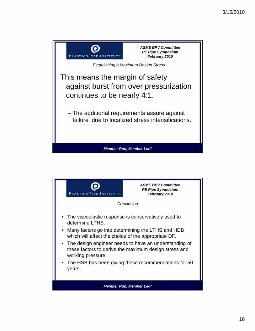
This means the margin of safetyThis means the margin of safety against burst from over pressurization continues to be nearly 4:1.
– The additional requirements assure against
Member Run, Member Led!
q gfailure due to localized stress intensifications.
ASME BPV CommitteePE Pipe Symposium
February 2010
Conclusion
Th i l ti i ti l d t• The viscoelastic response is conservatively used to determine LTHS.
• Many factors go into determining the LTHS and HDB which will affect the choice of the appropriate DF.
• The design engineer needs to have an understanding of these factors to derive the maximum design stress and
Member Run, Member Led!
working pressure.• The HSB has been giving these recommendations for 50
years.

3/15/2010
17
ASME BPV CommitteePE Pipe Symposium
February 2010
Member Run, Member Led!
www.PPXV.org