summary(kappa) nba 17octuu.diva-portal.org/smash/get/diva2:1359664/fulltext01.pdflist of papers the...
TRANSCRIPT

ACTAUNIVERSITATIS
UPSALIENSISUPPSALA
2019
Digital Comprehensive Summaries of Uppsala Dissertationsfrom the Faculty of Science and Technology 1863
Fat-IBC
A New Paradigm for Intra-body Communication
NOOR BADARIAH ASAN
ISSN 1651-6214ISBN 978-91-513-0770-1urn:nbn:se:uu:diva-393444

Dissertation presented at Uppsala University to be publicly examined in Häggsalen,Ångströmlaboratoriet, Lägerhyddsvägen 1, Uppsala, Wednesday, 27 November 2019 at09:15 for the degree of Doctor of Philosophy. The examination will be conducted in English.Faculty examiner: Dr. Ali Khaleghi (Norwegian University of Science and Technology).
AbstractAsan, N. B. 2019. Fat-IBC. A New Paradigm for Intra-body Communication. DigitalComprehensive Summaries of Uppsala Dissertations from the Faculty of Science andTechnology 1863. 116 pp. Uppsala: Acta Universitatis Upsaliensis. ISBN 978-91-513-0770-1.
In the last two decades, a significant development in the field of medical technologyoccurred worldwide. This development is characterized by the materialization of various bodyimplants and worn devices, that is devices attached to the body. These devices assist doctors andparamedical staff in effectively monitoring the patient’s health and helping increase patients’average life expectancy. Furthermore, the various implants inside the human body servedifferent purposes according to the humans’ needs. As this situation became more prominent,the development of protocols and of reliable transmission media is becomes essential toimprove the efficiency of inter-device communications. Positive prospects of the use of humantissue for intra-body communication were proven in recent studies. Fat tissues, for example,which also work as energy banks for human beings, can be potentially used in intra-bodycommunications as transmission media. In this thesis, the fat (adipose) tissue’s function asan intra-body communication channel was investigated. Therefore, various simulations andexperimentations were performed in order to characterize the reliability of the fat tissue in termsof communication, considering, for example, the effect that the variability in the thickness ofadipose and muscular tissues could have on the communication performance, and the possibleeffect that the variability in the transmitted signal power could have on the data packet reception.Fat tissue displays superior performance in comparison to muscle tissue in the context of a lowloss communication channel. For example, at 2.45 GHz, the path losses of ~0.7 dB/cm and~1.9 dB/cm were observed for phantom and ex-vivo measurements, respectively. At a higherfrequency of 5.8 GHz, the ex-vivo path loss was around 1.4 dB/cm. It was concluded fromthe results that the adipose tissue could function as a reliable medium supporting intra-bodycommunication even under low power transmitted signals. Moreover, although the presence ofthick blood vessels could degrade the signal strength, the results show that communication ispossible even under the presence of perturbant tissues. Overall, the results of this thesis wouldprovide a foundation in this area and assist researchers in developing innovative and solutionsfor intra-body communication.
Keywords: Fat-Intrabody Communication, Fat Tissue, Microwave, Propagation, Data PacketReception, Ex-vivo, Phantom, Communication, Reliability, Implants
Noor Badariah Asan, Department of Engineering Sciences, Solid State Electronics, Box 534,Uppsala University, SE-75121 Uppsala, Sweden.
© Noor Badariah Asan 2019
ISSN 1651-6214ISBN 978-91-513-0770-1urn:nbn:se:uu:diva-393444 (http://urn.kb.se/resolve?urn=urn:nbn:se:uu:diva-393444)

Dedicated tomy love, Zulkifli Shariff,
my lovely angel, Nur Alia Safiyya,my little hero, Alexander Dzulqarnayn,
and my beloved parents, Asan Abdullah & Minah Sidek.


List of papers
The thesis is based on the following papers, which are referred to in the textby their Roman numerals.
I. Noor Badariah Asan, Daniel Noreland, Emadeldeen Hassan, SyaifulRedzwan Mohd Shah, Anders Rydberg, Taco J. Blokhuis, Per-OlaCarlsson, Thiemo Voigt, and Robin Augustine. 2017. “Intra-bodyMicrowave Communication through Adipose Tissue,” HealthcareTechnology Letters, 4(4), pp. 115–121. Doi: 10.1049/htl.2016.0104
Part of this work was presented at Medicinteknikdagarna (MTD)by Swedish Society for Medical Engineering in Örebro, Sweden, 2016.
II. Noor Badariah Asan, Emadeldeen Hassan, Jacob Velander, SyaifulRedzwan Mohd Shah, Daniel Noreland, Taco J. Blokhuis, Eddie Wad-bro, Martin Berggren, Thiemo Voigt, and Robin Augustine. 2018.“Characterization of the Fat Channel for Intra-Body Communication atR-Band Frequencies,” Sensors, 18(9): 2752.Doi: https://doi.org/10.3390/s18092752
III. Noor Badariah Asan, Emadeldeen Hassan, Mauricio D. Perez, LayaJoseph, Martin Berggren, Thiemo Voigt, and Robin Augustine. 2019.“Fat-Intra Body Communication at 5.8 GHz Including Impacts of Dy-namic Body Movements” (manuscript).
IV. Noor Badariah Asan, Jacob Velander, Syaiful Redzwan Mohd Shah,Emadeldeen Hassan, Daniel Noreland, Taco J. Blokhuis, Thiemo Voigt,and Robin Augustine. “Reliability of the Fat Tissue Channel for Intra-Body Microwave Communication,” in 2017 IEEE Conference on An-tenna Measurements & Applications (CAMA), Tsukuba, Japan. 2017,pp. 310–313. Doi: 10.1109/CAMA.2017.8273435
V. Noor Badariah Asan, Jacob Velander, Syaiful Redzwan Mohd Shah,Mauricio D. Perez, Emadeldeen Hassan, Taco J. Blokhuis, ThiemoVoigt, and Robin Augustine.“Effect of Thickness Inhomogeneity in FatTissue on In-Body Microwave Propagation,” in 2018 IEEE Interna-tional Microwave Biomedical Conference (IMBioC), Philadelphia, PA,USA. 2018, pp. 136–138. Doi: 10.1109/IMBIOC.2018.8428872

Part of this work was presented at Swedish Microwave Days, An-tennEMB Symposium at Lund, Sweden, 2018.
VI. Noor Badariah Asan, Emadeldeen Hassan, Mauricio D. Perez, SyaifulRedzwan Mohd Shah, Jacob Velander, Taco J. Blokhuis, Thiemo Voigt,and Robin Augustine. 2019. “Assessment of Blood Vessel Effect onFat-Intrabody Communication Using Numerical and Ex-Vivo Models at2.45 GHz,” in IEEE Access, vol. 7, pp. 89886–89900.Doi: 10.1109/ACCESS.2019.2926646
Part of this work was presented at 2018 IEEE Conference on An-tenna Measurements & Applications (CAMA) in Västerås, Sweden,2018.
VII. Noor Badariah Asan, Carlos P. Penichet, Syaiful Redzwan MohdShah, Daniel Noreland, Emadeldeen Hassan, Anders Rydberg, Taco J.Blokhuis, Thiemo Voigt, and Robin Augustine. 2017. “Data PacketTransmission through Fat Tissue for Wireless IntraBody Networks,” inIEEE Journal of Electromagnetics, RF and Microwaves in Medicineand Biology, 1(2), pp. 43–51. Doi: 10.1109/JERM.2017.2766561
Part of this work was presented at 2017 First IEEE MTT-S Inter-national Microwave Bio Conference (IMBIOC) in Gothenburg, Sweden2017.
Reprints were made with permission from the publishers.

Author’s contributions
I. Major part of planning, experimental work, data analysis, and writingwith input from co-authors.
II. Major part of planning, experimental work, data analysis, and writingwith input from co-authors.
III. Major part of planning, experimental work, data analysis, and writingwith input from co-authors.
IV. Major part of planning, experimental work, data analysis, and writingwith input from co-authors.
V. Major part of planning, experimental work, data analysis, and writingwith input from co-authors.
VI. Major part of planning, experimental work, data analysis, and writingwith input from co-authors.
VII. Major part of planning, experimental work, data analysis, and writingwith input from co-authors.

List of papers not included in the thesis
The author has been involved in the following publications that are not part ofthis thesis, either due to contents overlapping that of appended papers, or dueto contents not related to the thesis.
VIII. Noor Badariah Asan, Robin Augustine, and Thiemo Voigt, “In-BodyInternet of Things Networks Using Adipose Tissue,” IEEE Internet ofThings (IoT) Newsletter, May 14, 2019.Retrieved from URL: https://iot.ieee.org/newsletter/may-2019/in-body-internet-of-things-networks-using-adipose-tissue.
IX. Noor Badariah Asan, Emadeldeen Hassan, Syaiful Redzwan MohdShah, Jacob Velander, Thiemo Voigt, and Robin Augustine, “Impactof Blood Vessels on Data Packet Transmission Through the Fat Chan-nel,” 2018 IEEE International RF and Microwave Conference (RFM),Penang, Malaysia 2018, 17–19 Dec 2018.
X. Noor Badariah Asan, Emadeldeen Hassan, Syaiful Redzwan MohdShah, Jacob Velander, Mauricio D. Perez, Thiemo Voigt, Taco J.Blokhuis, and Robin Augustine, “Effects of Blood Vessels on Fat Chan-nel Microwave Communication”, 2018 IEEE Conference on AntennaMeasurements & Applications (CAMA), Västerås, Sweden, September3–6, 2018, pp. 1–4. Doi: 10.1109/CAMA.2018.8530527
XI. Noor Badariah Asan, Mauricio D. Perez, Jacob Velander, and RobinAugustine, “Effect of the Fat Thickness Variation on In-Body Mi-crowave Propagation”, Swedish Microwave Days, AntennEMB Sympo-sium, Lund, Sweden, May 24–25, 2018.
XII. Noor Badariah Asan, Daniel Noreland, Syaiful Redzwan Mohd Shah,Emadeldeen Hassan, Anders Rydberg, Thiemo Voigt, and Robin Augus-tine, “Human Fat Tissue: A Microwave Communication Channel,” 2017First IEEE MTT-S International Microwave Bio Conference (IMBIOC),Gothenburg, 2017, pp. 1–4. Doi: 10.1109/IMBIOC.2017.7965801
XIII. Thiemo Voigt, Robin Augustine, Noor Badariah Asan, Mauricio D.Perez, Anders Ahlén, André Teixeira, Sam Hylamia, Christian Rohner,Wenqing Yan, Anna Nilsson, and Maria Mani, “Short Talk: LifeSec
– Don’t Hack my Body,” 4th IEEE European Symposium on Securityand Privacy & Cybersecurity and Privacy (CySeP), Stockholm, Swe-den, 10–14 June, 2019.
XIV. Thiemo Voigt, Robin Augustine, Noor Badariah Asan, Mauricio D.Perez, Anders Ahlén, André Teixeira, Sam Hylamia, Christian Rohner,Wenqing Yan, Anna Nilsson, and Maria Mani, “Poster: Tumor SensingPrivacy in In-Body Networks,” 4th IEEE European Symposium on Se-curity and Privacy & Cybersecurity and Privacy (CySeP), Stockholm,Sweden, 10–14 June, 2019.
XV. Syaiful Redzwan Mohd Shah, Jacob Velander, Parul Mathur, MauricioD. Perez, Noor Badariah Asan, Dhanesh G. Kurup, Taco J. Blokhuis,and Robin Augustine, “Split-Ring Resonator Sensor Penetration DepthAssessment Using In Vivo Microwave Reflectivity and Ultrasound Mea-surements for Lower Extremity Trauma Rehabilitation,” Sensors, vol.18, no. 2, pp. 636, Feb. 2018. Doi: https://doi.org/10.3390/s18020636
XVI. Syaiful Redzwan Mohd Shah, Noor Badariah Asan, Jacob Velander,Doojin Lee, Mauricio D. Perez, Marco Raaben, Taco J. Blokhuis,and Robin Augustine, “Frequency domain analysis of hip fracture us-ing microwave Split-Ring Resonator sensor on phantom model,” 2016IEEE Asia-Pacific Conference on Applied Electromagnetics (APACE),Langkawi, 2016, pp. 244–247. Doi: 10.1109/APACE.2016.7916434
XVII. Syaiful Redzwan Mohd Shah, Jacob Velander, Mauricio D. Perez,Noor Badariah Asan, Daniel Nowinski, Anders Lewén, Per Enblad,Robin Augustine, and Mina Rajabi, “Initial In-Vitro Trial for Intra-Cranial Pressure Monitoring Using Subdermal Proximity-Coupled Split-Ring Resonator,” 2018 IEEE International Microwave Biomedical Con-ference (IMBioC), Philadelphia, PA, 2018, pp. 73–75.Doi: 10.1109/IMBIOC.2018.8428854
XVIII. Syaiful Redzwan Mohd Shah, Jacob Velander, Mauricio D. Perez,Noor Badariah Asan, Robin Augustine, Parul Mathur, Dhanesh G. Ku-rup, and Taco J. Blokhuis, “Penetration Depth Evaluation of Split-RingResonator Sensor Using In-Vivo Microwave Reflectivity and UltrasoundMeasurements”, 12th European Conference on Antennas and Propaga-tion (EuCAP 2018), London, UK, 2018. Doi: 10.1049/cp.2018.0500
XIX. Syaiful Redzwan Mohd Shah, Jacob Velander, Noor Badariah Asan,Mauricio D. Perez, and Robin Augustine, “Assessment of Signal Trans-mission Using Microwave Sensors for Health Monitoring Applica-

tions,” 2018 IEEE International RF and Microwave Conference (RFM),Penang, Malaysia 2018, 17–19 Dec 2018.
XX. Jacob Velander, Syaiful Redzwan Mohd Shah, Mauricio D. Perez,Noor Badariah Asan, Robin Augustine, and Taco J. Blokhuis, “Multi-Functional Phantom Model to Validate Microwave Sensors for HealthMonitoring Applications”, 12th European Conference on Antennas andPropagation (EuCAP 2018), London, UK, 2018, pp. 1–5.Doi: 10.1049/cp.2018.0504
XXI. Jacob Velander, Syaiful Redzwan Mohd Shah, Mauricio D. Perez,Noor Badariah Asan, Daniel Nowinski, Anders Lewén, Per Enblad,and Robin Augustine, “A Four-Layer Phantom for Testing In-VitroMicrowave-Based Sensing Approach in Intra-Cranial Pressure Monitor-ing,” 2018 IEEE International Microwave Biomedical Conference (IM-BioC), Philadelphia, PA, 2018, pp. 49–51.Doi: 10.1109/IMBIOC.2018.8428861
XXII. Mauricio D. Perez, George Thomas, Syaiful Redzwan Mohd Shah, Ja-cob Velander, Noor Badariah Asan, Robin Augustine, Parul Mathur,Mohammad Nasir, Daniel Nowinski, and Dhanesh G. Kurup, “Prelimi-nary Study on Microwave Sensor for Bone Healing Follow-up after Cra-nial Surgery in Newborns”, 12th European Conference on Antennas andPropagation (EuCAP 2018), London, UK, 2018.Doi: 10.1049/cp.2018.1250
XXIII. Mauricio D. Perez, Syaiful Redzwan Mohd Shah, Jacob Velander,Marco Raaben, Noor Badariah Asan, Taco J. Blokhuis, and Robin Au-gustine, “Microwave sensors for new approach in monitoring hip frac-ture healing,” 2017 11th European Conference on Antennas and Propa-gation (EUCAP), Paris, 2017, pp. 1838–1842.Doi: 10.23919/EuCAP.2017.7928698
XXIV. Mauricio D. Perez, Viktor Mattsson, Syaiful Redzwan Mohd Shah, Ja-cob Velander, Noor Badariah Asan, Parul Mathur, Mohammad Nasir,Daniel Nowinski, Dhanesh G. Kurup, and Robin Augustine, “New Ap-proach for Clinical Data Analysis of Microwave Sensor Based BoneHealing Monitoring System in Craniosynostosis Treated Pediatric Pa-tients,” 2018 IEEE Conference on Antenna Measurements & Applica-tions (CAMA), Västerås, Sweden, September 3-6, 2018, pp. 1–4.Doi: 10.1109/CAMA.2018.8530485
Contents
1 Introduction . . . . . . . . . . . . . . . . . . . . . . . . . . . . . . . . . . . . . . . . . . . . . . . . . . . . . . . . . . . . . . . . . . . . . . . . . . . . . . . . . . . . . . . . . . . . . . . . 171.1 Intra-body communication . . . . . . . . . . . . . . . . . . . . . . . . . . . . . . . . . . . . . . . . . . . . . . . . . . . . . . . . . . . . 19
1.1.1 Capacitive coupling . . . . . . . . . . . . . . . . . . . . . . . . . . . . . . . . . . . . . . . . . . . . . . . . . . . . . . . . . 201.1.2 Galvanic coupling . . . . . . . . . . . . . . . . . . . . . . . . . . . . . . . . . . . . . . . . . . . . . . . . . . . . . . . . . . . . 211.1.3 Inductive coupling . . . . . . . . . . . . . . . . . . . . . . . . . . . . . . . . . . . . . . . . . . . . . . . . . . . . . . . . . . . 211.1.4 RF coupling . . . . . . . . . . . . . . . . . . . . . . . . . . . . . . . . . . . . . . . . . . . . . . . . . . . . . . . . . . . . . . . . . . . . . . 22
1.2 Fat-intrabody communication . . . . . . . . . . . . . . . . . . . . . . . . . . . . . . . . . . . . . . . . . . . . . . . . . . . . . . . 22
2 Fat-IBC channel modeling . . . . . . . . . . . . . . . . . . . . . . . . . . . . . . . . . . . . . . . . . . . . . . . . . . . . . . . . . . . . . . . . . . . . . . . . 262.1 Fat-IBC characterization . . . . . . . . . . . . . . . . . . . . . . . . . . . . . . . . . . . . . . . . . . . . . . . . . . . . . . . . . . . . . . . . 27
2.1.1 Anatomy of multi-layer tissue model . . . . . . . . . . . . . . . . . . . . . . . . . . . . . 272.1.2 Numerical modeling . . . . . . . . . . . . . . . . . . . . . . . . . . . . . . . . . . . . . . . . . . . . . . . . . . . . . . . . 292.1.3 Analytical channel modeling . . . . . . . . . . . . . . . . . . . . . . . . . . . . . . . . . . . . . . . . . . 32
2.2 Dielectric properties of tissue and materials . . . . . . . . . . . . . . . . . . . . . . . . . . . . . . . . 342.2.1 Dielectric properties theory . . . . . . . . . . . . . . . . . . . . . . . . . . . . . . . . . . . . . . . . . . . . 342.2.2 Coaxial probe measurement technique . . . . . . . . . . . . . . . . . . . . . . . . . . 362.2.3 Dielectric properties of tissues and materials . . . . . . . . . . . . . . . . 37
2.3 Measurements setup . . . . . . . . . . . . . . . . . . . . . . . . . . . . . . . . . . . . . . . . . . . . . . . . . . . . . . . . . . . . . . . . . . . . . . . 412.3.1 Topology-optimized waveguide-based probe design . . . . 42
3 Fat-IBC signal path loss . . . . . . . . . . . . . . . . . . . . . . . . . . . . . . . . . . . . . . . . . . . . . . . . . . . . . . . . . . . . . . . . . . . . . . . . . . . . 483.1 Signal path loss at 2.0 GHz . . . . . . . . . . . . . . . . . . . . . . . . . . . . . . . . . . . . . . . . . . . . . . . . . . . . . . . . . . . 493.2 Signal path loss at 2.4 GHz . . . . . . . . . . . . . . . . . . . . . . . . . . . . . . . . . . . . . . . . . . . . . . . . . . . . . . . . . . . 503.3 Signal path loss at 5.8 GHz . . . . . . . . . . . . . . . . . . . . . . . . . . . . . . . . . . . . . . . . . . . . . . . . . . . . . . . . . . . 543.4 Summary of the path loss . . . . . . . . . . . . . . . . . . . . . . . . . . . . . . . . . . . . . . . . . . . . . . . . . . . . . . . . . . . . . . 58
4 Factors affecting the performance of Fat-IBC . . . . . . . . . . . . . . . . . . . . . . . . . . . . . . . . . . . . . . . . . 604.1 Assessing the reliability of fat tissue as a channel supporting
intra-body microwave communication . . . . . . . . . . . . . . . . . . . . . . . . . . . . . . . . . . . . . . . . . 614.1.1 Numerical modeling for determining the reliability of
fat tissue as a communication channel . . . . . . . . . . . . . . . . . . . . . . . . . . . 614.1.2 Experimental setup for determining the reliability of
fat tissue as a communication channel . . . . . . . . . . . . . . . . . . . . . . . . . . . 624.1.3 Results and discussion on the reliability of fat tissue as
a microwave communication channel . . . . . . . . . . . . . . . . . . . . . . . . . . . . 634.2 Effect of thickness inhomogeneity in fat tissue on intra-body
microwave communication . . . . . . . . . . . . . . . . . . . . . . . . . . . . . . . . . . . . . . . . . . . . . . . . . . . . . . . . . . . . 654.2.1 Numerical modeling representing fat tissue thickness
distribution inhomogeneity . . . . . . . . . . . . . . . . . . . . . . . . . . . . . . . . . . . . . . . . . . . . . 65

4.2.2 Experimental setup to study the effect of fat tissuethickness variation . . . . . . . . . . . . . . . . . . . . . . . . . . . . . . . . . . . . . . . . . . . . . . . . . . . . . . . . . . . 65
4.2.3 Results and discussion to study the effect of fat tissuethickness variation . . . . . . . . . . . . . . . . . . . . . . . . . . . . . . . . . . . . . . . . . . . . . . . . . . . . . . . . . . . 66
4.3 Impact of blood vessels on intra-body communication at 2.45GHz . . . . . . . . . . . . . . . . . . . . . . . . . . . . . . . . . . . . . . . . . . . . . . . . . . . . . . . . . . . . . . . . . . . . . . . . . . . . . . . . . . . . . . . . . . . . . . . . . 694.3.1 Simulation model for assessment of the impact of
blood vessels on intra-body communication . . . . . . . . . . . . . . . . . 694.3.2 Experimental demonstration for assessment of the
impact of blood vessels on intra-body communication . 724.3.3 Results and discussion on the assessment of the impact
of blood vessels as a channel for intra-bodycommunication . . . . . . . . . . . . . . . . . . . . . . . . . . . . . . . . . . . . . . . . . . . . . . . . . . . . . . . . . . . . . . . . 72
4.4 Effect of misalignment in fat tissue on intra-body microwavecommunication . . . . . . . . . . . . . . . . . . . . . . . . . . . . . . . . . . . . . . . . . . . . . . . . . . . . . . . . . . . . . . . . . . . . . . . . . . . . . . . 784.4.1 Simulation and numerical modeling of effect of probe
misalignment in fat tissue . . . . . . . . . . . . . . . . . . . . . . . . . . . . . . . . . . . . . . . . . . . . . . . 784.4.2 Results and discussion on effect of probe
misalignment in fat tissue . . . . . . . . . . . . . . . . . . . . . . . . . . . . . . . . . . . . . . . . . . . . . . . 80
5 Packet transmission and perturbation sensing in the Fat-IBC . . . . . . . . . . . . . . . . 845.1 Data packet transmission via fat tissue . . . . . . . . . . . . . . . . . . . . . . . . . . . . . . . . . . . . . . . . . 85
5.1.1 Experimental details of data packet transmission viafat tissue . . . . . . . . . . . . . . . . . . . . . . . . . . . . . . . . . . . . . . . . . . . . . . . . . . . . . . . . . . . . . . . . . . . . . . . . . . . 85
5.1.2 Results and discussion on the received signalparameter for fat tissue . . . . . . . . . . . . . . . . . . . . . . . . . . . . . . . . . . . . . . . . . . . . . . . . . . . . 87
5.1.3 Packet reception with respect to transmitted power forFat-IBC . . . . . . . . . . . . . . . . . . . . . . . . . . . . . . . . . . . . . . . . . . . . . . . . . . . . . . . . . . . . . . . . . . . . . . . . . . . . . 88
5.2 Sensing applications of Fat-IBC . . . . . . . . . . . . . . . . . . . . . . . . . . . . . . . . . . . . . . . . . . . . . . . . . . . 89
6 Summary of the appended papers . . . . . . . . . . . . . . . . . . . . . . . . . . . . . . . . . . . . . . . . . . . . . . . . . . . . . . . . . . . . . 906.1 Fat-IBC characterization . . . . . . . . . . . . . . . . . . . . . . . . . . . . . . . . . . . . . . . . . . . . . . . . . . . . . . . . . . . . . . . . 90
6.1.1 Paper I – Intra-body microwave communicationthrough adipose tissue . . . . . . . . . . . . . . . . . . . . . . . . . . . . . . . . . . . . . . . . . . . . . . . . . . . . . 90
6.1.2 Paper II – Characterization of the fat channel forintra-body communication at R-band frequencies . . . . . . . . 91
6.1.3 Paper III – Fat-Intra Body Communication at 5.8 GHzIncluding Impacts of Dynamic Body Movements . . . . . . . . . 92
6.2 Factors affecting performance of the Fat-IBC . . . . . . . . . . . . . . . . . . . . . . . . . . . . . . 946.2.1 Paper IV – Reliability of the fat tissue channel for
intra-body microwave communication . . . . . . . . . . . . . . . . . . . . . . . . . . . 946.2.2 Paper V – Effect of thickness inhomogeneity in fat
tissue on in-body microwave propagation . . . . . . . . . . . . . . . . . . . . . 95

6.2.3 Paper VI – Assessment of blood vessel effect onfat-intrabody communication using numerical andex-vivo models at 2.45 GHz . . . . . . . . . . . . . . . . . . . . . . . . . . . . . . . . . . . . . . . . . . . 96
6.3 Data transmission in the Fat-IBC . . . . . . . . . . . . . . . . . . . . . . . . . . . . . . . . . . . . . . . . . . . . . . . . . . 976.3.1 Paper VII - Data packet transmission through fat tissue
for wireless intrabody networks . . . . . . . . . . . . . . . . . . . . . . . . . . . . . . . . . . . . . 97
7 Concluding remarks and future perspectives . . . . . . . . . . . . . . . . . . . . . . . . . . . . . . . . . . . . . . . . . 1007.1 Conclusions . . . . . . . . . . . . . . . . . . . . . . . . . . . . . . . . . . . . . . . . . . . . . . . . . . . . . . . . . . . . . . . . . . . . . . . . . . . . . . . . . . 1007.2 Future recommendations . . . . . . . . . . . . . . . . . . . . . . . . . . . . . . . . . . . . . . . . . . . . . . . . . . . . . . . . . . . . . 102
Svensk sammanfattning . . . . . . . . . . . . . . . . . . . . . . . . . . . . . . . . . . . . . . . . . . . . . . . . . . . . . . . . . . . . . . . . . . . . . . . . . . . . . . . . . 104
Acknowledgement . . . . . . . . . . . . . . . . . . . . . . . . . . . . . . . . . . . . . . . . . . . . . . . . . . . . . . . . . . . . . . . . . . . . . . . . . . . . . . . . . . . . . . . . . 107
References . . . . . . . . . . . . . . . . . . . . . . . . . . . . . . . . . . . . . . . . . . . . . . . . . . . . . . . . . . . . . . . . . . . . . . . . . . . . . . . . . . . . . . . . . . . . . . . . . . . . . . 111

Abbreviations
3D Three-dimensionalBAN Body-Area NetworkBAT Brown Adipose TissueBCC Body-Coupled CommunicationsBER Bit Error Ratebps bit per secondBPSK Binary Phase Shift KeyingCST Computer Simulation TechnologyCVD Cardiovascular DiseasesDI DeionizedE-field Electric FieldEM ElectromagneticFSDT Frequency-Selective Digital Transmissioni-BANs Intra-body Area NetworksIBC Intra Body CommunicationICD implantable Cardioverter/DefibrillatorsigWAT inguinal White Adipose TissueISM Industrial, Scientific and Medicalkbps kilo bit per secondMICS Medical Implant Communications ServiceMUT Material Under TestNFC Near Field CommunicationPANs Personal Area NetworksPEC Perfect Electric ConductorPML Perfectly Matched LayersPRR Packet Reception RatePT Perturbant TissueRF Radio FrequencyRF-NB Narrow-bandRF-UWB Ultra-wide-bandRFID Radio Frequency IdentificationRSS Received Signal StrengthRX ReceiverSAR Specific Absorption RateSDR Software Defined RadioSMA SubMiniature Version ATE Transverse ElectricTEM Transverse Electromagnetic
Continued on next page

TM Transverse MagneticTOPA Topology-Optimized Planar AntennaTX TransmitterUSRP Universal Software Radio PeripheralVNA Vector Network AnalyzervWAT Visceral White Adipose TissueWAT White Adipose TissueWBAN Wireless Body-Area NetworkWHO World Health OrganizationWMTS Wireless Medical Telemetry ServiceWSN Wireless Sensor Network

Thesis outline
This thesis is based on seven papers and divided into seven chapters.
Chapter 1 gives the motivations of this research and outlines an overviewof existing intra-body communication methods. At the end of this chapter,comprehensive introduction to the main subject of this thesis, Fat-IntraBodyCommunication (Fat-IBC) are given.
Chapter 2 presents the anatomical multilayer tissue model, followed bynumerical modeling and analytical channel modeling. The chapter continueswith the characterization of tissues and materials and follows with a compari-son of the dielectric properties of tissue-equivalent phantoms, ex-vivo animaltissues, and literature-reported human tissues. A dedicated measurementsetup for ex-vivo and a phantom verification of the simulation results are alsogiven in this chapter. Details of the probes’ prototypes and the probe-to-proberesults are presented (Papers I–III).
Chapter 3 discusses the design considerations of Fat-IBC with the specialfocus on the signal path loss at 2.0 GHz (Paper I), 2.4–2.45 GHz (Paper II),and 5.8 GHz (Paper III).
Chapter 4 summarizes the results and analyses performed from the ex-perimental works that have been conducted from various parameters suchas perturbants in the channel (Paper IV), fat thickness inhomogeneity(Paper V), and the effect of blood-vessels orientation, placement and num-bers of vessels on communication link (Paper VI). We further investigatedthe effect of the body movement on communication (Paper III). These areused to determine the factors affecting signal transmission in the Fat-IBC.
Chapter 5 discusses the issue of data packet transmission through fattissue supporting wireless connectivity of intra-body devices. The numer-ical modeling, experimental setup, and results are discussed (Paper VII).The possibility of using Fat-IBC as a sensing system is presented in Paper IV.
Chapter 6 provides a comprehensive summary of results and analysis fromthe studies conducted in Papers I, II, III, IV, V, VI, and VII.
Chapter 7 presents the conclusions of the thesis and potential avenues forfuture research.

1. Introduction
Throughout history, humans have developed certain mechanisms that promotethe accumulation of fat during periods of feast to survive during the upcomingperiods of famine and cold. However, what was once an asset has become aliability in our current society and, in particular, as recalled by Galgani et al.(2005) [1] “the obesogenic environment” because too much fat accumulationmay lead to obesity. As per statistical reports [2], fat contents varies with age.In males, the mean percentage body fat ranges increases from 22.9 % at age16–19 years to 30.9 % at age 60–79 years. These figures are significantlydifferent to those ones in females, as the mean percentage body fat rangesfrom 32.0 % at age 8–11 years to 42.4 % at age 60–79 years [3]. Therefore,essential fats in females (10–13 %) are approximately 2 to 3 folds more thanfor males (3–5 %).
Essentially, a healthy male body comprises 15 % of fat, while a femalebody comprises around 23 % of fat. For this reason, with 25 % of fat contentin a male body, he would be considered obese. As for females, they wouldbe considered obese when their bodies possess more than 32 % of fat con-tent. Obesity is linked with a number of diseases, such as metabolic disorders[4], cardiometabolic diseases [5], liver and kidney disorder [6], [7], chronicinflammation [8], and cardiovascular diseases (CVD) [9]. According to theWorld Health Organization (WHO), deaths related to cardiovascular diseasesare the most frequent. Approximately, 17.9 million people died from CVD in2016 [10]. However, most CVDs could be prevented through healthy diets,exercise, and weight control, as per WHO’s recommendation.
With this prospect in mind, the regular monitoring of human vital signs iscrucial for early and accurate diagnosis of patients’ medical condition and im-mediate commencement of proper treatment for them. For instance, patientswith Type-1 diabetes would be assisted with closed-loop insulin delivery sys-tems which would autonomously measure glucose levels and administer in-sulin based on glucose levels using the implanted glucose sensor and insulinpump devices [11].
In response to the above situations, the health care market has become afour trillion-dollar industry worldwide. It has been predicted that this figurewill double within ten years. Apart from the unparalleled growth in the hu-man population, nearly every country is faced with population aging [12]. Theincreasing environmental pollution occurs due to industrialization and urban-ization, leading to new pollution-related diseases [13]. Furthermore, there hasbeen a rapid increase in technology spending due to various factors, includ-ing the intensively competitive healthcare market, strong pressure to prevent
17

medical errors, and the need to comply with regulations among others. Med-ical implantable devices are gaining more popularity these days due to theirrole as life-saving devices. Medical implantable devices are getting more pop-ular these days because of the role as a life-saving device in addition to thesophistication and comfort that recent research and improved manufacturingprocesses have managed to bring in them [14], [15]. A wide range of medicalimplants is available with various functions. Pacemakers and defibrillators areused to monitor and treat cardiac conditions, and neuro-stimulators are usedfor deep brain stimulation to observe various brain-related illnesses, such asepilepsy, and Parkinson’s disease. Drug delivery systems are used in the formof infusion pumps, while a range of biosensors is used to obtain and processvarious bio-signals [16].
The human body consists of a fascinating communication network. Humanorgans provide metabolic functions to the body. As per previous discussion,early detection of diseases is important for immediate treatment. When a dis-ease is detected earlier, would it enable the implantation of certain artificialdevices at various locations in the human body which could ease the detectionof anomalies through the communication between them? A disability couldoccur after an accident or other medical cases due to the dysfunctionality ofone or more natural body communication links, but what if those links couldbe recovered? Although the efficient delivery of drugs to a certain body part isa challenging task, what if it could be improved, leading to the prevention ofdamaged cells in cancer treatment? What if the real-time statistics of humanvitals function could be identified? What if our intra-body communication net-work can communicate with the on-body and off-body devices as well? Theanswers and solutions to these questions would shape the future. Additionally,the answers to these questions would assist in managing the diseases and dis-orders mentioned above. This thesis aims to provide the foundation of the useof the human adipose (fat) tissue as a medium for communications within thebody. This new intra-body communication paradigm would provide answersto these questions in the future.
In this thesis, the use of human body tissues for intra-body communica-tion (IBC) was investigated. It was proven in studies of humans that poorlifestyle, eating habits, and pollution could bring adverse effects on the humanbody. Due to the significant increase in several diseases, such as hypertension,diabetes, and CVD, frequent monitoring of them is essential. Furthermore,early detection of diseases, such as cancer, would increase the average life ex-pectancy. Therefore, new techniques and methods which could facilitate earlydisease detection are important. Moreover, if human body tissues could be uti-lized to guide the signals with vital and control information more efficiently,implanted devices would not only be able to communicate in a better mannerwith the outer world but also with other implanted devices.
By in-cooperating human tissues for IBC, the materialization gap in thistechnology can be fulfilled and new horizons in this field can be opened. An
18

important literary contribution in this matter was by Wegmüller (2007) [17],where the human body was categorized as a transmission medium that couldtransmit electrical currents and develop the electrical models of the humantissue. Additionally, individual-specific variations of the transmission charac-teristics were investigated in a clinical trial.
1.1 Intra-body communicationThe first work in the field of intra-body communication was performed byZimmerman (1996) [18]. The idea of Personal Area Networks (PANs) wascontributed to illustrate that electronic devices that were attached near a hu-man body could form a network and exchange data through capacitive cou-pling. The state-of-the-art method in electronic devices with highly power-efficient characteristics and the advancements in the field of wireless commu-nication have expanded new horizons in human body area networks (BANs).In human body-area communication, multiple devices are worn or placed in-side or within the vicinity of the human body. These devices could form awireless link or a small-scale wireless network to share data and enable newservices. Notably, IBC may also contribute to endless opportunities in thefield of healthcare services by connecting various on/in-body devices to formthe BAN of personal health information. For instance, patients with diabetescould use an automatic insulin pump which autonomously measures glucoselevels and administers insulin upon high levels of glucose. A sensor, whichmay be developed in the future, may reduce the occurrences of heart attackor stroke, decreasing the burden from hospitals by avoiding frequent patientvisits [19].
One of the possible scenarios of the communication between the sensor andthe external world is shown in Figure 1.1. A system consisting of a wirelesspower receiver, rechargeable battery unit, and wireless communication sys-tem was implanted inside the human body [20]. The implant performed itsintended task and transmitted human vitals to the mobile phone through Blue-tooth. A wireless charging mechanism was also provided to avoid surgeriesfor replacing batteries.
There are two primary methods for signals to be coupled into the body forIBC, namely capacitive coupling and galvanic coupling. Other, less popularapproaches also exist, such as inductive coupling, ultrasound, and classicalRF coupling in the form of narrow-band (RF-NB) and ultra-wide-band com-munication (RF-UWB). The next section provides further details on these ap-proaches.
19

Figure 1.1. Implantable medical device communicates with the external world.
1.1.1 Capacitive couplingIn capacitive coupling, a signal is applied to a transceiver electrode, and anelectric field is build up [21]. This approach mainly aims to maximize thecoupling between the transceiver and the human body, thus reducing the inter-ference because of ambient noise. Furthermore, signal electrodes are used fortransmission and reception. The signal from the transmitter creates an elec-tric potential, followed by the connection between the ground electrode andthe earth ground. Directed by the dielectric characteristics of the human bodytissues, the major part of the electric current travels between the two transmit-ter electrodes, while a minor part travels towards the two receiver electrodes.This small current leads to a potential difference which is detected in variousways by the receiver electrodes. As the capacitive coupling requires a returnpath through the parasitic earth ground, external interference could disrupt theIBC.
The maximum data rate, which was achieved through a capacitive cou-pling, was 60 Mbps multi-level coded frequency-selective digital transmission(FSDT) for body channel communication [22]. As for the frequencies above60 kHz, capacitive coupling displayed a more superior performance comparedto galvanic coupling. Figure 1.2(a) illustrates the channel model of capacitivecoupling for IBC.
20

(a) Capacitive coupling. (b) Galvanic coupling.
Figure 1.2. Channel model for intra-body communication: (a) capacitive coupling(b) galvanic coupling.
1.1.2 Galvanic couplingIn galvanic coupling, a signal is controlled by the applied current flow, whilethe human body could be considered as the waveguide [23]. In comparisonto capacitive coupling, the propagation of the current in galvanic couplingthrough the body does not involve any return path, as shown in Figure 1.2(b).Therefore, this method is less susceptible to noise. Furthermore, besides thesmall energy absorption in the tissue, the galvanic coupling-based tissue com-munication is effective for frequencies below 1 MHz. However, at low fre-quencies, the signal propagation would heat up the tissues. Without a properadministration of the heating process, the tissue may be damaged [24]. An-other drawback of this technique is that the bandwidth is lower compared tocapacitive coupling, which leads to a lower data rate.
1.1.3 Inductive couplingIn inductive coupling, the electromagnetic coupling is used to provide a com-munication link to implanted devices, by placing the external coil close to thepatient that couples to a coil implanted below the skin surface. The implant ispowered by the coupled magnetic field. The best power transfer is achievedin inductive coupling when it is used in large transmitting and receiving coils.Therefore, this method could be used effectively if space is not a constraint[25]–[27]. For example, Hannan et al. [28] states that “based on current liter-
21

ature, we believe that the inductive coupling link is the suitable method to beused to power the battery-less devices”. However, in the case of IBC, a com-pact size of implants is required. However, this technique is not capable ofsupporting a high data rate and initiating a communication session from insideof the body [29]. Therefore, it is not suitable for IBC.
1.1.4 RF couplingRF based IBC is one of the alternative techniques that can increase the band-width and enable two-way data communication. Popularly known as WirelessMedical Telemetry Service (WMTS) and Medical Implant CommunicationsService (MICS), RF-NB functions on a band dedicated to medical applica-tions. The details of the bands reserved for these applications are illustrated inTable 1.1 [30].
Table 1.1. RF-NB Band. Copyright ©2019, IEEE [30].Band Frequency range Application(s)
WMTS608–614 (MHz)
Remote patient monitoring1395–1400 (MHz)1429–1432 (MHz)
MICS / MedRadio 401–406 (MHz) On-body and embedded sensor communication2.36–2.4 (GHz)RF-Ultra wideband 3.1–10.6 (GHz) Intra-body communicationMilimeter wave >30 (GHz) Device to device communication
1.2 Fat-intrabody communicationThe transmission of data out of many parts of the body is a challenging pro-cess [31]. Utilizing fat tissues as a communication channel in order to estab-lish communication between implanted devices separated by some distance iscalled fat intra-body communication, Fat-IBC. However, low-frequency prop-agation (kHz range) is not an ideal choice for IBC as it results in lower band-width and higher path loss. Microwave frequencies are highly attenuated byskin and muscle tissues due to the higher dielectric coefficient of skin andmuscles [32]–[34]. It could be seen IBC works well for R-band (1.70 to 2.60GHz) communication in previous work [35].
The pioneer work for Fat-IBC was done by the thesis author in a previousresearch article [36], where various aspects of Fat-intrabody communicationwere explored [37],[38]. Essentially, fat functions as a good communicationchannel for frequencies around 2.0 GHz [36]. The loss is smaller than for othertissues and the bandwidth is higher which means that functionalities such ascardiac pacemakers, implantable cardioverter/defibrillators (ICD), and neuro-prosthetics can be supported. It is worth mentioning that Fat-IBC research is
22

in its early state and some applications with the present-day tools availablecannot be realized today due to number of reasons which includes lack ofbandwidth inside the body.
Figure 1.3 shows a human body with multiple implants such as artificialkidney, heart sensor, and liver sensor. Wireless communication is the mostideal method for communication between these sensors to take place. Besidesthis method, fat tissue could be used as a microwave communication betweenthem. In the cases where the sensors are separated by a large distance, the sig-nal strength may be attenuated as it propagates through the fat tissue. In orderto enhance the signal strength, a repeater node may be used as an amplifierstage. All the body vitals are collected by the aggregator node that transfersinformation to the outside of the human body.
Figure 1.3. Conceptual rendering of fat intra-body microwave communication (Fat-IBC) network. Paper VII. Reprinted, with permission, from [39]. Copyright ©2017,IEEE.
The goal of this thesis is to provide the foundation of the use of the hu-man adipose (fat) tissue as a medium for communications within the body. Inthis thesis, the channel for Fat-IBC is modeled numerically and analytically.This thesis could contribute to the construction of an end to end network bya quantitative path loss for the Fat-IBC obtained based on a numerical andexperimental approach. In the next chapter of the thesis discusses the relia-
23

bility of the behavior of the fat channel in the presence of perturbants, inho-mogeneity, and blood vessels. Finally, the fat tissues were used in this studyas the medium of microwave communication to transfer and receive a packet.This process involved real data or health information and determined the datapacket reception.
24

2. Fat-IBC channel modeling
In this chapter, the channel for Fat-IBC is modeled numerically and analyti-cally. The dielectric properties measurement technique is presented and alsothe experimental setup, including the topology-optimized waveguide-basedprobe designs toward the channel modeling of fat-intrabody microwavecommunication are presented in Papers I–III and are summarized in thischapter as follows:
• Section 2.1: The anatomy of a multi-layered tissue model, which consistsof skin, fat, and muscle is presented. Subsequently, numerical simulationmodels and analytical modeling for parallel plate waveguide are shown. InPaper I, the method to characterize fat or adipose tissue and muscle tissuefor intra-body communication at 2.0 GHz is presented. The characterizationis extended to the Industrial, Scientific and Medical (ISM) band frequenciesat 2.4 GHz and 5.8 GHz, respectively. The skin and muscle communica-tion are compared to Fat-IBC. The parallel plate waveguide hypothesis isdiscussed in Paper II, and the analytical channel modeling based on theparallel plate waveguide is explained.
• Section 2.2: The measurement techniques and instruments used for measur-ing the dielectric properties are discussed. The dielectric properties of thetissue-equivalent phantom, the ex-vivo porcine tissue, and other materialsare presented and compared.
• Section 2.3: This section details the three main components of the measure-ments setup for the Fat-IBC system. A thorough discussion is made on thethree different prototypes of the topology-optimized waveguide-based probeused in Papers I–III and their elements.
25

2.1 Fat-IBC characterization2.1.1 Anatomy of multi-layer tissue modelThe human body is a complex structure comprising different tissues, organs,and bone structures of varying geometries. The human body parts such asarms, legs, and torso basically consist of three types of tissues; namely skin,fat, and muscle which were approximated to simplify the geometrical andphysical properties of an anatomical model.
The work in Papers I–VII is based on the simplified three-layered (i.e.,skin-fat-muscle) tissue model. Due to several reasons, the bone layers wereexcluded in numerical and experimental studies. For example, to establisha network between sensors, the implanted devices used for the delivery ofdrugs such as insulin are commonly located in the soft human tissue [40].Besides, in some areas, the bone is located as the inner layer in the humanbody. The laterally transmitted signals are attenuated by the muscles and theyhardly reach the bone. Figure 2.1 shows the extraction method of the three-layered tissue model. It is obvious that fat tissue is widespread around themodel and generally surrounds all the major organs in the human body1.
Figure 2.1. The model shows that the vital organs are surrounded by adipose tissue.The smaller picture of the 3 types of tissues outlines how the intra-body microwaveis transmitted through the fat tissue. Paper II. Reprinted, with permission, from [35]Copyright ©2018, MDPI.
1Coronal plane of the Emma voxel human model from the CST software
26

Human body fat can be classified into three types, namely white fat, brownfat, and brite fat. White adipose tissue (WAT) is the major adipose part inadults and is the prime storage location of energy. When energy is needed,fatty acids are released from WAT by lipolysis [41]. WAT is extensively dis-persed all over the body, separate/specific depots can be illustrious: visceralwhite adipose tissue (vWAT) primarily covers internal organs, whereas in-guinal white adipose tissue (igWAT) is present under the skin. Brown adiposetissue (BAT) is a distinct class of adipose organ which is present in all mam-mals including humans, however, pig is an exception [42]. The prime role ofBAT is to perform non-shivering thermogenesis action by burning lipids andglucose, resulting in heat production. Unlike WAT, BAT are located only inthe supraclavicular, neck, and perirenal regions of the human body [43]. Therole of brite fat is to reserve brown adipose tissue that can be induced by coldacquaintance to release energy [44]. To establish a communication channelthrough a tissue, one has to rely on the geometrical integrity of the channel.Since WAT provides a stable tissue layer, when compared to other types oftissues, it is selected as a potential candidate for communication.
Characteristics of fat tissue have been widely studied in the literature [45]–[47]. The relative permittivity and electric conductivity of the tissue depend ona number of factors, namely the frequency, moisture level, temperature, fluid,and mineral contents. It is important to understand the behavior of the tissuesand how to measure dielectric properties of the tissues in order to transmitand receive electromagnetic radiations in the biological tissues. Generally,animal bodies are studied in order to develop and implement new technolo-gies. Porcine tissues have great resemblance with the human tissues due tometabolic similarities, and the results obtained from porcine tissues can bemore or less mapped to human tissues [48]. A detailed investigation has beenconducted by Karacolak et al. (2012) [49] to measure dielectric properties ofporcine skin, and its similar to human skin.
The relative permittivity and conductivity of human muscle and fat tissuegiven by Werber et al. (2006) [50] is tabulated in Table 2.1. From Table 2.1, athigher frequency, it can be seen that the relative permittivity decreases as thefrequency increases while the conductivity increases. The observations whichcan be made are: for higher frequencies, the relative permittivity goes downslowly, while the conductivity increases gradually with higher frequencies.Furthermore, muscles have a high water content, whereas the water contentsin fat is lower. Based on the values in Table 2.1, it is worth investigatingthe viability of muscle and fat tissue for the purpose of the communicationchannel.
27

Table 2.1. Relative permittivity and conductivity of human fat and muscle tissue.Copyright ©2006, IEEE [50].Parameter /Frequency (Hz)
Relative permittivity Conductivity (S/m)Fat Muscle Fat Muscle
100 4.57 × 10⁵ 9.33 × 10⁶ 2.08 × 10⁻² 2.27 × 10⁻¹
100 k 92.9 8.9 × 10³ 2.44 × 10⁻² 3.62 × 10⁻¹
400 M 5.58 57.1 4.11 × 10⁻² 7.69 × 10⁻¹
1 G 4.6 42.8 5.85 × 10⁻¹ 10.6
2.1.2 Numerical modelingThe 3D EM simulation commercial package CST Microwave Studio (CSTStudio Suite - Dassault Systémes, France) from CST2 software is used for thepreliminary study. The main interest in designing and developing a numericalmodel is to assess the dependence of the attenuation factor on different tissuelayer properties such as variation in the tissue thicknesses, and the distancebetween the transmitter and receiver.
The transmission channel of the biological tissues was characterized by de-signing two models, which comprise of the skin, fat (adipose), and muscle lay-ers (arranged from top to bottom). To examine the effect of human anatomy onsignal propagation, two separate models were designed with the same lengthand width of 50 mm (W ) × 100 mm (L) as shown in Figure 2.2. To provethat the fat tissue is a better communication channel compared to the mus-cle tissue, the results of using the fat tissue as a communication channel werecompared against the results obtained when using the muscle tissue. Figure2.2(a) shows the waveguide port excitation in the fat tissue, and Figure 2.2(b)shows the waveguide port excitation in the muscle tissue. In the third dimen-sion, the thickness for the fat (T F) and muscle (T M) tissues are varied from5 mm to 45 mm with 5 mm steps. The skin thickness, T S were fixed at 2mm based on the average thickness of the skin [51], [52]. The distance Lwas selected according to the distance between major vital organs, for exam-ple, kidney-liver, kidney-pancreas, and heart-liver, and also from the previousexperimental models used in other published studies [53]–[55].
A transmitting probe (TX) is used to launch a horizontal electromagneticsignal towards the opposite side of the tissue to the receiving probe (RX),which detects the signal. As a proof of concept, the built-in waveguide portsin the CST package were used to simulate the electromagnetic probes (TX andRX) with a radiation boundary condition surrounding the models to simulatenon-reflecting environments. For the numerical studies, the human tissue3 inthe frequency range of 1–10 GHz was used.
In Paper I, the signal transmission in fat and muscle layers was investi-gated. From the results, it is observed that the signal transmission improves
2Computer Simulation Technology: https://www.cst.com3Bio-tissue materials from CST software
28

(a) Transmission in the fat tissue. (b) Transmission in the muscle tissue.
Figure 2.2. The preliminary model to study the impact of the thickness variation in fatand muscle layers on the transmitted and reflected signals.
as the thickness of the fat layer increases until 25 mm and does not changemuch when the thickness is increased further. In muscle, the signal transmis-sion was found to be inefficient due to high dielectric losses in the layer. Thecomparative study was extended further to compare the performance of signaltransmission between the fat and muscle tissues at a frequency of 5.8 GHz.Figure 2.3 shows the comparison of the signal transmission through the fatand muscle tissues. It can be seen that the signal transmission through the fattissue is higher compared to the muscle tissue, which is expected due to thedifference in dielectric constants. The attenuation in the muscle tissue is morethan twice compared to the one in the fat tissue. For example, when the fatthickness is 25 mm, and the muscle thickness is 30 mm, the signal attenuationis –30 dB, –35 dB, and –36 dB at 2.0 GHz, 2.4 GHz, and 5.8 GHz, respec-tively. The signal attenuates considerably in the muscle, by –94 dB, –101 dB,and –107 dB, respectively.
To observe the channel characteristics, in Paper VII, measurements onthree cases were performed, where the details are summarized in Table 2.2.According to Paper VII, results for Case 1 show that by varying the thicknessfrom 10 mm to 35 mm, S21 increases until the thickness reaches 25 mm andthen becomes approximately constant. Results also suggest that varying thethickness of muscle has a negligible effect on S11 and S21. Results for Case2 suggest that by varying the thickness of fat or muscle tissue, no significantchanges are observed for S11 and S21. When comparing the results of Case1 with Case 2, it could be concluded that fat tissue is a better channel, whichgives approximately 10 dB better signal strength than the muscle tissue. ForCase 3, measurement results suggest that the amplitude of S21 roughly de-creases by 2 dB per 20 mm for the case of phantom and 4 dB per 20 mm forthe case of ex-vivo. Furthermore, the transmission loss is higher for the mus-cle tissue than for the fat tissue. Thus, fat tissue is more suitable as a channelfor intra-body communication as compared to the muscle tissue.
29

Figure 2.3. The impact on the transmission coefficient, S21, due to varying fat andmuscle layer thicknesses.
Table 2.2. Cases to conduct experiments.
Cases Experiment 1 Experiment 2Tissue Thickness Tissue Thickness
Case 1:Waveguide alignedwith fat layer
Skin Fixed at 2 mm Skin Fixed at 2 mmFat 10–35 mm Fat Fixed at 25 mmMuscle Fixed at 30 mm Muscle 20–45 mm
Case 2:Waveguide alignedwith muscle layer
Skin Fixed at 2 mm Skin Fixed at 2 mmFat 10–35 mm Fat Fixed at 25 mmMuscle Fixed at 30 mm Muscle 20–45 mm
Case 3:Signal transmissiondistance
Probe alignment in thefat layer.
Probe alignment in themuscle layer.
Channel length varies from 20 to 100 mmwith a step of 20 mm.
From this finding, it is indicative that the fat tissue is capable of becom-ing the transmission medium for in-body communication or labeled as Fat-intrabody communication (Fat-IBC). When fat tissue is sandwiched with theskin and the muscle tissues, a structure similar to a parallel plate waveguide isformed. In general, a parallel plate waveguide is formed by having two con-ductors on both sides of a dielectric material. The high contrast in dielectricproperties between fat on one hand and skin and muscle, on the other hand,allows the signal to be confined within the fat layer.
30

In this research, it also strived to improve the performance of the Fat-IBCtechnique by increasing the signal transmission. The theoretical limitationsof open-ended rectangular waveguides were superseded by mean of topologyoptimized probes that give a better matching along a wider range of frequen-cies. These probes were used as both transmitter and receiver in the studies.With the help of numerical and experimental characterization, deeper under-standing and improvement of the performance of the Fat-IBC technique, wereobtained.
2.1.3 Analytical channel modelingSince the parallel plate waveguide is formed by two conducting plates, it cansupport transverse electric (TE), transverse magnetic (TM), and also trans-verse electromagnetic (TEM) modes.
By using an analytical channel model for a parallel plate waveguide, thepropagation was studied in the z-direction keeping both plates infinite in thex-direction. Therefore, a simple parallel plate waveguide structure shown inFigure 2.4 is considered, where d is the distance separating the two perfectelectric conductor (PEC) plates.
Figure 2.4. Parallel plate waveguide structure.
The boundary conditions are classified as to whether Ez or Hz existsaccordingly as below:
TEM : Ez = 0, Hz = 0TE : Ez = 0, Hz � 0TM : Ez � 0, Hz = 0
According to Pozar [56], the transverse field components in TM modes canbe computed as:
Hx =jωεkc
An cosnπy
de− jβ z (2.1a)
Ey =− jβ
kcAn cos
nπyd
e− jβ z (2.1b)
Ex = Hz = 0 (2.1c)
For TM mode, when n = 0 and β = k = ω √με , and Ez = 0, the Ey andHx fields are constant at any x-y plane. TEM mode has no cutoff frequency;
31

therefore in this condition, the TM0 mode is identical to the transverse elec-tromagnetic (TEM) mode. For n > 0, it corresponds to a different TM mode(i.e., TM1, TM2, TM3, etc.) and each mode has its own propagation constantand field expression.
Next, the transverse field components for TE modes are:
Ex =jωμkc
Bn sinnπy
de− jβ z (2.2a)
Hy =jβkc
Bn sinnπy
de− jβ z (2.2b)
Ey = Hx = 0 (2.2c)
For TE mode, when n = 0, then Ex = Hy = 0 there is no TE0 mode. Thepropagation constant, β and the cutoff frequency, f c are the same as TMnmode.
The propagation constant of the TMn mode and the TEn mode are given as:
β =
√k2 −
(nπd
)2(2.3)
The cutoff frequency of the TMn and TEn mode is defined to be at the onsetof propagation.
fc =n
2d√με
(2.4)
where:fc = rectangular waveguide cut-off frequency in Hzd = distance between the platesn = mode propagation number (e.g., 1, 2, 3)
It should be emphasized that the concept of Fat-IBC is not equivalent to aparallel waveguide since the skin and muscle characteristics are lossy, whichwill not give perfect conductor boundary conditions.
32

2.2 Dielectric properties of tissue and materialsThe dielectric properties of any material provide an insight into the feasibilityof using that material for potential applications. In the work of this thesis, thedielectric properties of each material and tissues that are used during the labo-ratory experimentation were measured to confirm that these values are similarto the real human tissue values. It is also important to understand the propertiesof the dielectric materials, especially the permittivity and loss tangent at theoperating conditions. That will be explained in the next section. According toKeysight Technologies application note [57], there are six measurement tech-niques for the dielectric constant and the loss tangent of a material. The meth-ods include Coaxial Probe, Transmission Line, Free Space, Resonant Cavity,Parallel Plate, and Inductance measurement. In order to select the most appro-priate measurement technique, different factors such as the frequency range,accuracy, material form (i.e., liquid, powder, semi-solid, solid, or sheet), andthe convenience to handle the measurement must be taken into consideration.Upon deliberation, the coaxial probe measurement technique was selected asit is an ideal method to measure homogeneous and semi-solid material.
2.2.1 Dielectric properties theoryThe permittivity of dielectric material, denoted by ε , has a real and an imagi-nary part,
ε = ε ′ − jε ′′ (2.5)
where the real part ε ′ = εrε0 relates the material dielectric constant εr to thefree space permittivity ε0 ≈ 8.854×10⁻¹² F/m. The dielectric constant refersto the efficiency of dielectric material in storing the electric energy, whereasthe imaginary part ε ′′ indicates loss of electrical energy [58]. The imaginarypart ε ′′ is labeled as the loss factor. The loss factor includes the effects ofdielectric loss [59]. It is common to combine the material dielectric and ohmiclosses to define the so-called loss tangent.
tanδ =ωε ′′+σ
ωε ′(2.6)
where σ is the material electric conductivity. The numerator of (2.6) is knownas the real part of the displacement current, and the denominator is its imag-inary part [56]. Moreover, in some occasions the numerator terms is calledthe material effective conductivity σeffective = ωε ′′ +σ . Figure 2.5 shows arepresentation of the loss tangent as a vector diagram.
For loss-free materials, the loss tangent is zero. The loss tangent increasesas the dielectric or ohmic losses increase. Therefore, the loss tangent is typi-cally used to indicate the energy dissipation in the material.
33

Figure 2.5. The loss tangent defined by the vector diagram.
Table 2.3. Comparison of dielectric properties between the skin, fat, and muscle tissue[60].
Frequency(GHz) Tissue
Relative Permittivity,ε ′r
Conductivity,(S/m)
Loss Tangent,tanδ
2.4Skin 42.92 1.56 0.27Fat 5.29 0.10 0.15Muscle 52.79 1.71 0.24
5.8Skin 38.62 4.3 0.34Fat 4.95 0.29 0.18Muscle 48.48 4.96 0.32
In communication systems, a material with a large dielectric loss has a highdegree of dielectric absorption and thus higher attenuation. Hence, this rep-resents a limitation in the transmission of long-range signals. From the per-spective of Fat-IBC, the fat tissue has lower dielectric loss than the skin andmuscle tissue. Table 2.3 presents the dielectric properties of the skin, fat, andmuscle tissue [60]. It can be seen that the permittivities of the skin and muscleare about 8–10 times higher, which makes the wave propagate slower and havemore cycles to attenuate itself in a given physical length. Therefore, fat tissuecan be considered to be an effective low-loss communication medium.
34

2.2.2 Coaxial probe measurement techniqueIn this study, the open-ended coaxial dielectric probe techniques was appliedto evaluate the lossy material sample over different ranges of frequencies. Theopen-ended coaxial probe consists of a flat cut-off section of the transmis-sion line. The reflection coefficient (S11) of an open-ended coaxial line isdependent on the dielectric properties of the material under test (MUT) that isattached to it [57] making the method suitable for this study. Furthermore, itcan be used on liquid, solid, or semi-solid samples.
For the measurement of the dielectric properties for a tissue-equivalentphantom and ex-vivo tissue samples, the slim form probe in the Agilent85070E (now Keysight N1501A) Dielectric Probe Kit was used. A proper cal-ibration procedure is necessary to produce reliable dielectric properties mea-surements. In general, for coaxial probe measurements, a three-load standardcalibration procedure for one-port error correction is applied. There are threecommon standards used for coaxial probe calibration, including open, short,and water. During the calibration process, the normal three standard calibra-tions as mentioned above, would be performed at the end of the probe basedon the guidance of the 85070E Dielectric Probe Kit software. For this study,a conducting elastomer-based standard was used for short calibration. As forload calibration, any liquid with known dielectric properties can be used, andthe deionized (DI) water was chosen for this purpose. The calibration wasperformed at the reference plane of the probe, and the probe was connectedvia a cable with a 2.4 mm to 3.5 mm adapter to the Vector Network Analyzer(VNA) or FieldFox Handheld RF and Microwave Analyzer.
For the measurement of a solid MUT, the probe was brought into contactwith the flat surface of the material. The measured reflected signal is a func-tion of the fringing electromagnetic (EM) fields interacting with the MUTat the open-ended aperture of the probe. Based on the reflected signal, thesoftware is able to calculate and display the complex permittivity in differentformats, including dielectric constant, dielectric loss factor, loss tangent, orCole-Cole plots. According to the datasheet of the 85070E Dielectric ProbeKit, the measured value typically has an uncertainty of 10 %. In order toreduce any additional systematic error, five repeated dielectric measurementswere taken to ensure that the standard deviation of these repetitions was muchsmaller than the typical instrument uncertainty. Figure 2.6 shows the exampleof N9918A FieldFox Handheld Microwave Analyzer operating as a VNA andthe dielectric probe kit setup.
35

Figure 2.6. N9918A FieldFox Handheld Microwave Analyzer and 85070E DielectricProbe Kit setup.
2.2.3 Dielectric properties of tissues and materialsTo improve the performance of Fat-IBC, various types of tissue-equivalentphantom and ex-vivo porcine tissue were used in this study and reported inPapers I–VII. Figures 2.7–2.9 show the comparison between the dielectricproperties for tissue-emulating phantom materials, ex-vivo porcine tissues,and human tissues as a function of frequency. Agar-based compounds wereused to fabricate phantom materials to emulate the typical response of thehuman skin and muscle tissues to microwave signals. Similarly, rubber- andoil-based materials were used to fabricated phantom materials emulating fattissue. These skin, muscle, and fat phantom materials were used to create fatchannel models for laboratory studies. Samples of skin, fat, and muscle tissueswere separated from a fresh part of a porcine belly. The fat and muscle tissueswere also minced. The skin slab samples and the minced fat and muscle sam-ples together with very-low-permittivity 3D printed molds were used to createfat channel models for laboratory studies as well.
As can be seen in Figures 2.7–2.9, in the frequency of interest, the dielec-tric properties are almost constant for fat tissue, while for the skin and muscleslightly linear. This is because the skin and the muscle are frequency depen-dent in the dielectric constant and conductivity.
36

In order to have a more realistic scenario to study the Fat-IBC approach inlaboratory, it is crucial to characterize the different types of materials includ-ing tissue-equivalent phantoms and ex-vivo tissues that can emulate the humanfat tissue as well as the skin and muscle tissues in a better manner. Figure 2.8shows the comparison of the real part of the permittivity (ε ′r) and loss factor(ε ′′r ) for different materials, which emulate the microwave properties of the fattissue. In Paper I, a synthetic rubber material was used to develop the rect-angular waveguide probes, and an adhesive putty was used to mimic the fattissue channel. The frequency used in the paper was 2.0 GHz. In Paper II andIII, a vulcanized rubber material was used to fill the fat-equivalent in the rect-angular waveguide probes operated at R-band (1.7–2.6 GHz) frequencies andF-band (4.9–7.05 GHz) frequencies. The vulcanized rubber was chosen overthe synthetic rubber because its properties are similar to the human tissue, andits robust and solid nature makes it easily machined into different geometri-cal shapes. The vulcanized rubber and oil-based phantom materials have bothbeen used as phantom materials for a fat channel model.
1 2 3 4 5 6 7 8 9 10
Frequency (GHz)
0
10
20
30
40
50
60
0
10
20
30
40
50
60
Figure 2.7. Dielectric properties of different materials of the skin tissue for 1–10 GHzfrequency range.
37

1 2 3 4 5 6 7 8 9 10
Frequency (GHz)
-2
0
2
4
6
8
10
-2
0
2
4
6
8
10
Figure 2.8. Dielectric properties of different materials of the fat tissue for 1–10 GHzfrequency range.
1 2 3 4 5 6 7 8 9 10
Frequency (GHz)
0
10
20
30
40
50
60
0
10
20
30
40
50
60
Figure 2.9. Dielectric properties of different materials of the muscle tissue for 1–10GHz frequency range.
The real part of the relative permittivity (dielectric constant) and loss tan-gent for different materials of the skin, fat, and muscle tissues that are relevantfor medical implants are listed in Tables 2.4–2.6. The data is given for thefrequencies of 2.4 GHz and 5.8 GHz, which constitutes two ISM frequency
38

bands. The human tissue data were extracted from Gabriel et al. [58]. It isimportant to highlight that the fat tissue has significantly lower permittivityand conductivity than skin and muscle tissues.
Table 2.5 shows that the loss tangent of the oil-based phantom is slightlyhigher than the actual tissue. This may result in substantial variation in thetransmission signal results when compared to the human and the ex-vivo tis-sue. Despite that, the oil-based phantom allows the phantom to be more flex-ible. Future experimental studies should take the dynamics associated withhuman movements into consideration. Flexible and elastic phantom materi-als will enable the incorporation of dynamics in the future. The measureddielectric dispersion profiles for the considered materials and/or tissues wereused in our numerical fat channel models as a primary approach to validate themeasurement results.
Table 2.4. Relative permittivity (real part) and loss tangent for different materials ofthe skin tissue at 2.4 GHz and 5.8 GHz.
Material Relative Permittivity, ε ′r Loss Tangent, tan δ2.4 GHz 5.8 GHz 2.4 GHz 5.8 GHz
Agar-based phantom 44 ± 4 41 ± 4 0.28 ± 0.03 0.36 ± 0.04Ex-vivo porcine 40 ± 4 33 ± 3 0.34 ± 0.03 0.45 ± 0.04Human tissue 38 ± 2 35 ± 2 0.28 ± 0.01 0.33 ± 0.02
Table 2.5. Relative permittivity (real part) and loss tangent for different materials ofthe fat tissue at 2.4 GHz and 5.8 GHz.
Material Relative Permittivity, ε ′r Loss Tangent, tan δ2.4 GHz 5.8 GHz 2.4 GHz 5.8 GHz
Synthetic rubber 4.5 ± 0.5 4.5 ± 0.5 0.017 ± 0.002 0.04 ± 0.004Adhesive putty 5.0 ± 0.5 4.7 ± 0.5 0.01 ± 0.001 0.016 ± 0.002Vulcanized rubber 5.9 ± 0.6 5.6 ± 0.6 0.11 ± 0.01 0.01 ± 0.001Oil-based phantom 6.8 ± 0.7 5.2 ± 0.5 0.41 ± 0.04 0.37 ± 0.04Ex-vivo porcine 5.5 ± 0.5 5.0 ± 0.5 0.19 ± 0.02 0.15 ± 0.01Human tissue 5.3 ± 0.3 5.0 ± 0.2 0.15 ± 0.01 0.18 ± 0.01
Table 2.6. Relative permittivity (real part) and loss tangent for different materials ofthe muscle tissue at 2.4 GHz and 5.8 GHz.
Material Relative Permittivity, ε ′r Loss Tangent, tan δ2.4 GHz 5.8 GHz 2.4 GHz 5.8 GHz
Agar-based phantom 49 ± 5 39 ± 4 0.23 ± 0.02 0.48 ± 0.05Ex-vivo porcine 51 ± 5 43 ± 4 0.34 ± 0.03 0.44 ± 0.04Human tissue 53 ± 3 48 ± 2 0.24 ± 0.01 0.32 ± 0.02
39

2.3 Measurements setupIn this section, the measurement setups used to obtain the experimentaldata for the characterization of the Fat-IBC techniques (Papers I–III) areexplained. Figure 2.10 shows the measurement setup as applied in the Fat-IBCsystem. Measurements were conducted to demonstrate the performance ofthe signal transmission through the fat tissue using the Fat-IBC technique.
The measurement setup consists of three main components:1. A pair of rectangular waveguide-based probes as a transmitter (TX) and
receiver (RX).2. A microwave analyzer, for example, the FieldFox Handheld RF and Mi-
crowave Analyzer or Vector Network Analyzer.3. A three-layered tissue consisting of skin, fat, and muscle as a fat channel
model.
Figure 2.10. The Fat-IBC measurement setup.
40

The transmitter (TX) probe radiates the electromagnetic (EM) waves fromPort 1 of the microwave analyzer. The signal travels through the fat tissue,which is the transmission medium before reaching the receiving probe (RX) atthe other end. As the EM wave travels away from the transmitter, the strengthof the signal decreases.
Papers I–III use the same experimental setup except for Component 1, therectangular waveguide-based probes. Different probes were used to examinethe performance at different frequencies, namely 2.0 GHz, 2.4 GHz, and 5.8GHz. The probe in Paper I was used for determining the performance of thesignal transmission at a frequency of 2.0 GHz, whereas other different probeswere used to examine the performance at frequencies of 2.4 GHz and 5.8 GHzin Papers II and III, respectively. In Papers IV–VI, the measurement setupswere similar except for changes in Component 3. Several modifications inthe fat channel model were performed to examine the factors that influencethe performance of Fat-IBC. In Chapter 5, the experimental setup reported inPaper VII was used in which the Components 1 and 2 were both differentfrom Papers I–VI.
2.3.1 Topology-optimized waveguide-based probe designTo achieve our vision to demonstrate the concept in a real scenario, three typesof topology-optimized waveguide-based probes were designed and developed,and each of them was optimized for a specific frequency band. The designof the probes is to determine the insertion loss in the fat-channel based on arealistic probe excitation.
The first research direction which explored the frequency 2.0 GHz wasinspired by a numerical study, as explained in Paper I. Considering thatthe probe should operate in the ISM band, the necessary step was taken tomake it possible for the realization of the implants. Therefore, the secondresearch focused on investigating the use of typical ISM band at 2.4–2.45GHz to be incorporated into the medical application by implementing thesecond probe at R-band frequencies (Paper II). In Paper III, another ISMband frequency of 5.8 GHz was chosen to allows a small probe size design,taking into consideration that higher frequencies are beneficial. Apart fromminiaturization purposes, high frequencies allow larger bandwidth, and,therefore, higher bit rates.
The probe consists of three elements:1. A rectangular waveguide probe filled with the fat-equivalent phantom.2. A standard SubMiniature version A (SMA) connector.3. A topology-optimized planar antenna (TOPA).
41

Figure 2.11 shows the cross-sections of the three probes to explain the el-ements inside the probes and their dimensions. The probes are similar towaveguide-coax transitions with Figure 2.11(a) fed on the broad side of thewaveguide at a distance of λ/4 to the end side, and Figures 2.11(b) and 2.11(c)are fed like an end-launcher waveguide-coax probe. In addition, the waveg-uides are filled with fat-equivalent material and excited by the TOPA element,which is in yellow color in the figures to match with the fat in the transmissionchannel. The topology-optimized planar antenna is immersed at the center ofthe equivalent fat-filled (i.e., rubber compound) copper waveguide. An SMAconnector is attached at the end of the waveguide probe.
(a) 2.0 GHz waveguide probe.
(b) 2.4 GHz waveguide probe.
(c) 5.8 GHz waveguide probe.
Figure 2.11. The cross-section view of the topology-optimized planar antenna and therectangular waveguide probes used to characterized the Fat-IBC. Yellow color in thefigures is the TOPA element.
42

First prototype: R-band probe, optimized for 2.0 GHzThe design of the probe is chosen from the standard waveguide size. Thecross-section of the waveguide-based probe was based on a standard WR430waveguide, but scaled down by the square root of the dielectric constant offat tissue. This is because, it helps to reduce the size for the same operatingfrequency. The WR430 waveguide is chosen according to the needs of thestudy, which are the operating frequency ranges and the inner dimensions ofthe waveguide aperture. To ensure the continuity of the electromagnetic wavesfrom the probe to the fat tissue, the probe was filled with synthetic rubber withdielectric properties similar to the fat tissue. A topology-optimized planar an-tenna was then immersed at the center of the synthetic rubber and the wholerubber structure was covered with copper tape to form a coaxial-to-waveguideprobe. To validate the performance of the fabricated probes, their scatteringparameters were measured. Figure 2.12 shows the simulated and measuredscattering parameters of the probe-to-probe measurement. The probe-to-probeS21 results are the attenuation of the waveguide probes at 0 mm channel lengthat certain frequency. The S21 results will be used as a reference for the sub-sequent measurements, especially when determining the signal path loss inChapter 3. As can be seen from the results, this prototype did not performwell in the entire range of the R-band. However, it fulfilled the requirementof operating well at a frequency of 2.0 GHz. Here, the probe-to-probe S21results at 2.0 GHz is –1.5 dB and –2.9 dB for simulation and measurement,respectively. With this in mind, it is also strived to work harder to improve thedesign of the probes to achieve better signal coupling between the two probesin the fat tissue.
1 1.2 1.4 1.6 1.8 2 2.2 2.4 2.6 2.8 3
Frequency (GHz)
-40
-35
-30
-25
-20
-15
-10
-5
0
Ma
gn
itu
de
(d
B)
S11
- Measurement S21
- Measurement
S11
- Simulation S21
- Simulation
Figure 2.12. Scattering parameters of the probe-to-probe measurements (first proto-type).
43

Second prototype: R-band probe, optimized for 2.40–2.45 GHzThe second prototype was successfully produced and tested. A novelwaveguide-based probe that performed excellently within the R-band frequen-cies (1.7–2.6 GHz) in the fat tissue. This second prototype was developedbased on a standard WR430, but scaled down by the square root of the dielec-tric constant of fat tissue as well. The design of the topology-optimized planarantenna (TOPA) was improved, which is an essential element in the probe de-velopment. The synthetic rubber of the probe was substituted with vulcanizedrubber. A slot was made at the center of the rubber to immerse the TOPA.During the development of this prototype, the copper plate was used to formthe outer layer of the probes. Figure 2.13 shows the measured and simulatedscattering parameters of probe-to-probe measurements. The results show anexcellent match between the two probes, and the signal coupling recorded wasalmost constant in the range of R-band frequencies. The attenuation of theprobe-to-probe (reference) for this prototype is essentially a constant value of2 dB over the whole R-band frequencies and at 2.4–2.45 GHz ISM band.
1 1.2 1.4 1.6 1.8 2 2.2 2.4 2.6 2.8 3
Frequency (GHz)
-40
-35
-30
-25
-20
-15
-10
-5
0
Ma
gn
itu
de
(d
B)
S11
- Measurement S21
- Measurement
S11
- Simulation S21
- Simulation
Figure 2.13. Scattering parameters of the probe-to-probe measurements (second pro-totype).
44

Third prototype: F-band probe, optimized for 5.8 GHzThe motivation to design a third probe was to explore other ISM band frequen-cies and to broaden the possibility of using the Fat-IBC technique at higherfrequencies. A standard WR75 waveguide was chosen in the development ofthe probe with a volume of 9.9 × 19.1 × 14.3 mm3. Similar to the previousprobes, this probe also consisted of the topology-optimized planar antenna. Itused the same fabrication method as the second prototype, where vulcanizedrubber with dielectric properties that are similar to the human fat tissue wasused. Figure 2.14 shows the simulated and measured scattering parameter ofthe third prototype. The waveguide covered the F-band frequencies of 4.9–7.05 GHz, including the 5.8 GHz ISM band. The probe-to-probe (reference)has an attenuation of 2 dB and 2.2 dB for simulated and measured results,respectively.
3 3.5 4 4.5 5 5.5 6 6.5 7 7.5 8
Frequency (GHz)
-40
-35
-30
-25
-20
-15
-10
-5
0
Ma
gn
itu
de
(d
B)
S11
- Measurement S21
- Measurement
S11
- Simulation S21
- Simulation
Figure 2.14. Scattering parameters of the probe-to-probe measurements (third proto-type).
45
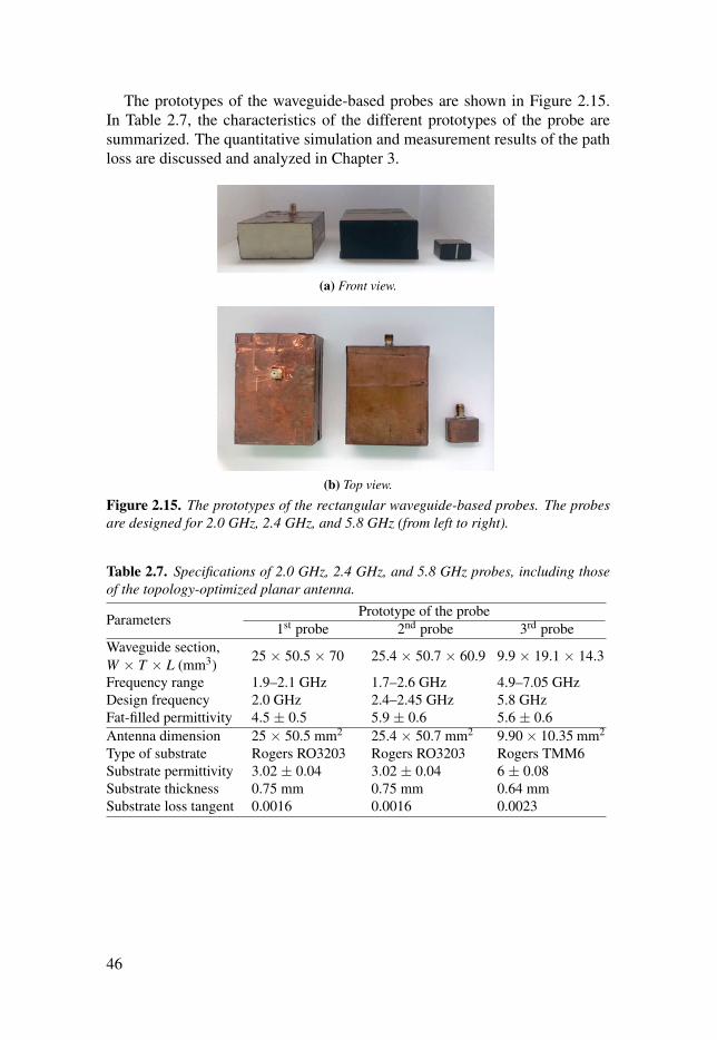
The prototypes of the waveguide-based probes are shown in Figure 2.15.In Table 2.7, the characteristics of the different prototypes of the probe aresummarized. The quantitative simulation and measurement results of the pathloss are discussed and analyzed in Chapter 3.
(a) Front view.
(b) Top view.
Figure 2.15. The prototypes of the rectangular waveguide-based probes. The probesare designed for 2.0 GHz, 2.4 GHz, and 5.8 GHz (from left to right).
Table 2.7. Specifications of 2.0 GHz, 2.4 GHz, and 5.8 GHz probes, including thoseof the topology-optimized planar antenna.
Parameters Prototype of the probe1st probe 2nd probe 3rd probe
Waveguide section,W × T × L (mm3)
25 × 50.5 × 70 25.4 × 50.7 × 60.9 9.9 × 19.1 × 14.3
Frequency range 1.9–2.1 GHz 1.7–2.6 GHz 4.9–7.05 GHzDesign frequency 2.0 GHz 2.4–2.45 GHz 5.8 GHzFat-filled permittivity 4.5 ± 0.5 5.9 ± 0.6 5.6 ± 0.6Antenna dimension 25 × 50.5 mm2 25.4 × 50.7 mm2 9.90 × 10.35 mm2
Type of substrate Rogers RO3203 Rogers RO3203 Rogers TMM6Substrate permittivity 3.02 ± 0.04 3.02 ± 0.04 6 ± 0.08Substrate thickness 0.75 mm 0.75 mm 0.64 mmSubstrate loss tangent 0.0016 0.0016 0.0023
46

3. Fat-IBC signal path loss
Path loss, or path attenuation, is defined as the reduction in the power density(attenuation) of an electromagnetic wave as it propagates through a medium[61]. Notably, path loss varies across certain frequencies when the signal prop-agates through different media [62]. Furthermore, it is a major component inthe analysis and design of the link budget of a communication system. It en-ables the reuse of wave frequency after certain distances in a communicationnetwork, contributing to an increase in the system’s capacity and efficient useof the allocated frequency for its relevant applications. Although the channel’scharacteristics could be determined by modeling the path loss, the communi-cation link would be broken when the signal is not amplified or regenerated.In this study, a quantitative path loss for the Fat-IBC was obtained based on anumerical and experimental approach.
The path loss is caused by various phenomena, such as reflection, refrac-tion, aperture medium coupling loss, absorption, and the reflective and refrac-tive index of the incident surface among others. In the case of Fat-IBC, thereare various factors of path loss in the communication channel, namely thepropagation medium (dry or moist air, skin, fat, muscle), the distance betweenthe transmitter and the receiver, and the height and location of antennas. Bymodeling the path loss, new insights could be developed regarding the chan-nel characteristics, contributing to the construction of an end to end network.In this study, numerical modeling and experimentation for Fat-IBC were per-formed, leading to notable results of path losses at 2.0 GHz, 2.4 GHz, and 5.8GHz. Moreover, the characterization techniques possibly held a significance,especially in the cases where more than two frequency bands were concur-rently used to propagate in the fat tissue. In mathematical terms, it could beexpressed through Eq. (3.1).
PLdB =Pin
Pout=−10log10 |S21|2 =−|S21|dB (3.1)
47

This chapter elaborates on parameter considerations, which are the essen-tial components in designing Fat-IBC systems. The remaining sections of thischapter are summarized as follows:
• Section 3.1: In Paper I, the signal path loss at 2.0 GHz was investigatedto characterize the Fat-IBC. The signal transmission results from the tissue-equivalent phantom and ex-vivo tissue were measured and simulated.
• Section 3.2: In Paper II, further investigation was performed on the char-acterization of the signal transmission and the signal path loss at 2.4 GHz,which had not been identified in Paper I.
• Section 3.3: Besides the purpose of miniaturization for implanted devicesapplication, further characterization of the 5.8 GHz ISM band frequency wasa remarkable aspect of this study. The signal path loss of the homogeneousmodel on the Fat-IBC are illustrated in Paper III.
For Papers I–III, the three-layered structure consisting of skin, fat, andmuscle with a total length of 100 mm was used. The coupling coefficient, S21was demonstrated for tissue-equivalent phantom and ex-vivo. The length ofthe channel was made to range from 20 mm to 100 mm with a step size of 20mm. Furthermore, the thickness of the skin was determined as 2 mm, with amuscle thickness of 30 mm. The experiments conducted were compared withthe simulations for both phantom and ex-vivo environments.
3.1 Signal path loss at 2.0 GHzThe signal path loss at 2.0 GHz was investigated to describe the Fat-IBC. Thefirst optimized probe prototype was used for simulation and experimentation.The signal transmission results from the tissue-equivalent phantom and ex-vivo tissues were obtained through the aforementioned approaches.
As a result, there was a good correlation between S21 measurement andthe simulation results. It could be seen that for the simulated and measuredresults, the path loss for the phantom was 1 dB/cm. In the case of the ex-vivo,the path loss was condensed by 2 dB/cm. Moreover, the improvement in signaltransmission was noticeable with the thickness of adipose tissues. As for theadipose tissue, the ideal signal-coupling occurred at 25 mm tissue thicknessor higher. Therefore, 25 mm could be considered as the optimal thickness fortransmission through the adipose tissue. Additionally, the amplitude of the S21was observed at –15 dB. There was no significant change observed by varyingthe muscle layer thickness. Overall, satisfactory results between simulationand measurements were obtained.
48

3.2 Signal path loss at 2.4 GHzTo observe the signal path loss at 2.4 GHz, the second optimized probeprototype was used to study the average path loss of the fat channel. After theinvestigation of the signal path loss behavior, it was summarized into threecases. Figure 3.1 summaries the signal path loss behavior in the three cases:
(a) Case 1: The three-layered skin-fat-muscle waveguide section.
(b) Case 2: A dielectric rectangular waveguide section made of fat as a fat channel model.
(c) Case 3: A parallel-plate waveguide section filled with fat as a fat channel model.
Figure 3.1. The fat channel model cases for (a) generic three-layered structure, (b)in the absence of skin and muscle tissue, and (c) in the presence of parallel copperplates. Paper II. Reprinted, with permission, from [35]. Copyright ©2018, MDPI.
In respect of the first case (see Figure 3.1(a)), the R-band frequencies forS21 were constant over the frequency range from 1.7 GHz to 2.6 GHz. Thesefrequencies then transitioned with –3.5 dB to approximately –9 dB due to theincrease in the channel length from 20 mm to 100 mm. For every 10 mmchannel length, the average path loss was nearly 0.7 dB. This was followed byS21 results for porcine tissue. Similar to the results regarding the three-layeredphantoms, a similar trend could be seen from S21 for the porcine tissue. To bespecific, a flat response was obtained over the R-band frequencies. Further-more, the magnitude of S21 amounted to –7 dB with a 20 mm channel length.Another remarkable observation of S21 was the decrease in its magnitude by1.9 dB for each 10 mm increase in the channel length. Based on the compar-ison between the results of phantom and ex-vivo tissue, it could be concluded
49

that the propagation loss in the phantom and the ex-vivo environments is ∼0.7dB/cm and ∼1.9 dB/cm respectively.
In further investigations on the first case, the skin and muscle tissues weredetached from the model. The S21 was evaluated between the transmitting andreceiving probes in the sole presence of the fat tissue (see Figure 3.1(b)). Inthis case, the fat tissue was similar to a dielectric waveguide [63]. Further-more, the value of S21 between the two probes was reduced compared withthe case of the presence of skin and muscle layers (generic structure). Thisreduction was due to the leakage of the transmitted signal into the free spacefrom the boundaries of the waveguide. Nevertheless, this signal leakage fromthe waveguide was prevented by the skin and muscle. The S21 between theprobes was also constant across the R-band frequencies. This was followed bya minor change in S21 when the length of the channel increased from 20 mmto 100 mm.
The parallel plate waveguide structure is illustrated in Figure 3.1(c). Thebehavior of the channel was investigated upon the absence of the skin andmuscle tissues. Notably, these tissues were replaced by two parallel plates ofcopper. As expected, the path losses were reduced. This is because the cop-per did not allow the leakage of signal from the waveguide, contributing to anoverall increase in the magnitude of S21. Furthermore, the presence of skinand muscle tissues preserved the transmission coefficient. However, their ab-sence would lead to decreased signal strength. Compared to the absence of thecopper plate, S21 displayed a better response when the fat tissue was coveredby the copper plate for the second time. In a nutshell, based on the comparisonbetween the results of all aforementioned three cases, it could be concludedthat the three-layered structure was better than a single layer fat channel (di-electric waveguide) in terms of a communication link. It should be noted thatdielectric waveguide phenomenon is not applicable in real life as the humanbody naturally consists of three-layered, skin-fat-muscle tissues. The three-layered channel model functioned as a waveguide structure, where the pathloss was lower than the path loss in the fat dielectric waveguide. In contrast,the waveguide structure path loss was higher than the copper plate waveguide,because of the lossy nature of the skin and muscle tissues compared to thecopper.
50

An observation was conducted on the electric field distribution for certaincases. Through this observation, new insights could be developed into thepropagation of the signal when it was launched to the channel and any phe-nomena occurring during the transmission. As shown in Figure 3.2(a), theelectric field was observed when the two probes were located in the free space.High values could be seen from the electric field only located within the trans-mitting probe. Meanwhile, a mismatch was found between the probe and thefree space. Based on the fat dielectric waveguide structure in Figure 3.2(b), theleakage of a significant portion of E-field was found in the free space, followedby the acquirement of a small amount of energy at the receiving probe. In re-spect of the third case in Figure 3.1(a) and the results shown in Figure 3.2(c),the signal was confined between the skin and the muscle, which could be seenas a wave flow through the fat channel.
(a) The free space channel.
(b) The fat layer channel.
(c) The three-layered fat channel.
Figure 3.2. The simulated electric field distribution of three models at 2.4 GHz. PaperII. Reprinted, with permission, from [35]. Copyright ©2018, MDPI.
51

Based on the statistics shown in Figure 3.3, a minimum average path losswas present in the third case (copper plates) where the path loss was at0.15 dB/cm for simulation and measurement. Meanwhile, the maximum av-erage path loss was found in the second case (single layer fat channel), wherethe loss was at 0.65 dB/cm for simulation and 0.55 dB/cm for measurement. Itwas indicated from these findings that fat only channel has a significant waveleakage. Nevertheless, proper protection of the leakage signal was present inparallel plates, making it ideal for skin, fat, and muscle configuration. Overall,the above findings were in an agreement at 2.4 GHz. A remarkable correlationcould also be seen from the simulated and measured results.
Ref. 20 40 60 80 100
Distance (mm)
0
5
10
15
20
25
30
Estim
ate
d p
ath
lo
ss (
dB
)
Case 1: Three-layered fat channel (S) Case 1: Three-layered fat channel (M)
Case 2: Single layer fat channel (S) Case 2: Single layer fat channel (M)
Case 3: Parallel copper plates (S) Case 3: Parallel copper plates (M)
Figure 3.3. The comparison of simulated and measured path loss summary for cases1, 2, and 3 at 2.4 GHz.
52

3.3 Signal path loss at 5.8 GHzIn this section, the simulation and experimental details are demonstrated forthe observation of the signal path loss at 5.8 GHz. Therefore, the modeling ofthe system was conducted through several methods, which will be elaboratedin the following parts of this section. The S21 parameters were then registeredfor each configuration.
The Fat-IBC system was modeled through four configurations, namelyType A, Type B, Type C, and Type D. In Type A, the three-layered struc-ture was modeled in a way that a constant width, W of all the layers wasused. Meanwhile, Figure 3.4(a) illustrates the three-layered structure for TypeA configuration. As for Type B, we extended the channel width, W extend to 50mm. The thickness of skin and muscle in Type B was perceived to be similarto Type A. The Type B arrangement is shown in Figure 3.4(b). In respect ofType C configuration, the width of the channel was kept to be fixed as Type A,with an increase in the thickness of the fat. The structure of Type C is shownin Figure 3.4(c). In the case of Type D, the attributes of Type B and Type Cwere simultaneously incorporated by increasing the thickness and the widthof the fat-channel and the formation is shown in Figure 3.4(d).
(a) Type A : Exact probe size. (b) Type B : Extended fat width.
(c) Type C : Extended fat thickness. (d) Type D : Extended fat width and thickness.
Figure 3.4. Four types of model structures for the measurement of signal loss at 5.8GHz. Paper III. Adapted, from [64].
53

The third prototype was used to launch the electromagnetic signal in thefat tissue for the phantom (see Figure 3.5(a)) and ex-vivo (see Figure 3.5(b))setup. In order to have a general picture, the results are presented over thefrequency ranged from 3 to 8 GHz.
(a) Phantom measurement.
(b) Ex-vivo measurement.
Figure 3.5. The configuration setup for (a) Phantom and (b) Ex-vivo environment.Paper III. Adapted, from [64].
The transmission coefficient S21 was then measured and computed. Thiswas followed by a discussion on the results of Type A to Type D configura-tions for ex-vivo and phantom. The simulated and measured S21 results for alltypes were compared with the ex-vivo and the phantom across various chan-nel lengths. In measuring S21, N9918A FieldFox Handheld Analyzer was usedto record the transmission coefficient. Provided that this analyzer possessed amaximum dynamic range of –45 dBm for all the frequency ranges, the plottingwas conducted based on its limit in terms of dynamic range. Therefore, themeasurement results for the dynamic range lower than –45 dB were regardedas defective measurements and complemented by simulation results.
It could be seen from Type A S21 results that the simulated and experimentalresults were in a good agreement with each other. Through the noticeable lossin the signal strength due to the increasing channel length, an average path lossof 3 dB/cm at 5.8 GHz was observed. Provided that the loss tangent of the fat-equivalent phantom was twice the loss tangent of the ex-vivo tissue, it was
54

predicted that the average path loss would amount to 6 dB/cm. The S21 resultsare illustrated by taking Type B into account, specifically its configuration forthe simulation and experimentation of the ex-vivo and phantom. A similartrend in this matter was also present in the results for Type A configuration.Furthermore, the average channel path loss almost amounted to 3.2 dB/cm,with a fat-equivalent phantom amounting to 5.1 dB/cm decay. In respect ofType C, the signal coupling increased by more than 10 dB at 100 mm distancecompared to Type A and Type B. Through the comparison between Type Cresults at 60 mm channel length, an increase in the values of S21 could be seencompared to the values of S21 in Type A and Type B, which amounted to by2.5 dB and 4.6 dB.
In the case of Type D, the fat tissue was extended around the probes for bothenvironments, namely ex-vivo porcine tissue and tissue-equivalent phantom.Notably, Type D was a case that was almost equivalent to real-life scenarios,where the fat tissue surrounds the implant. It could be seen that the differ-ence between Type C and D results was not significant in terms of their signaltransmission. This finding emphasized that the fat thickness poses a significantinfluence on the signal transmission. The S21 simulated for a 100 mm ex-vivochannel length amounted to –25.6 dB, while the measured S21 amounted to–25 dB. Meanwhile, for the phantom at 60 mm channel length, the simulatedS21 amounted to –45 dB, while the measured S21 amounted to –44. dB.
Overall, Type C and D displayed lower signal path loss, which was similarto Type A and B. The increased fat thickness in Type C and D did not onlyindicate the alteration between Type A and B, but it also recovered path loss.It could also be seen that the measurement results were in a good agreementwith the simulation results. Through observation on all average distances, thepath loss per centimeter for the ex-vivo porcine tissue and the tissue-equivalentphantom environment was estimated. Specifically, as for the ex-vivo config-uration for Type A, both the simulated and measured path loss amounted to3.2 dB/cm. In respect of the phantom for the same type, the simulated pathloss amounted to 5.3 dB/cm, with 7.4 dB/cm measured path loss. In the caseof the ex-vivo configuration for Type B, simulated and measured path lossamounted to 3.2 dB/cm and 3.4 dB/cm, respectively. Meanwhile, the simu-lated path loss for phantom amounted to 5.1 dB/cm, 6.3 dB/cm measured pathloss. On the other hand, with respect to the ex-vivo for Type C, the simulatedand measured path loss amounted to 1.5 dB/cm, while the phantom displayed4.4 dB/cm and 4.0 dB/cm simulated and measured path losses, respectively.Lastly, in the case of the ex-vivo average path loss for Type D, the simulatedpath loss amounted to 1.4 dB/cm. As for the phantom for the same type, thesimulated path loss of 4.6 dB/cm was recorded, with 4.7 dB/cm of measuredpath loss.
55

Table 3.1 and Table 3.2 display a summary of the simulated and measuredtransmission coefficient S21 for different methods. An emphasis was placedon the channel length for ex-vivo porcine tissue and tissue-equivalent phantomat 5.8 GHz. The values in Figure 3.6 were plotted based on the results inTable 3.1. It could also be seen from Figure 3.6 that different environmentspossessed diverse path loss profiles.
Table 3.1. The S21 simulated and measured results for Type A–D at a varying channellength for ex-vivo equivalent tissue at 5.8 GHz. Paper III. Adapted, from [64].
Types /Distance
Measured (Simulated), S21 (dB)20 mm 40 mm 60 mm 80 mm 100 mm
Type A -8.8 (-8.4) -15.3 (-14.6) -21.9 (-21.3) -27.9 (-27.4) -34.6 (-34.1)Type B -11.9 (-10.2) -18.5 (-17.0) -25.5 (-24.4) -31.4 (-31.7) -37.9 (-37.3)Type C -13.4 (-12.1) -16.3 (-14.9) -19.6 (-18.0) -22.4 (-21.2) -25.4 (-24.2)Type D -14.7 (-14.0) -18.6 (-16.8) -22.6 (-22.3) -24.0 (-23.6) -25.6 (-25.0)
Table 3.2. The S21 simulated and measured results for Type A–D at a varying channellength for phantom equivalent tissue at 5.8 GHz. Paper III. Adapted, from [64].
Types /Distance
Measured (Simulated), S21 (dB)20 mm 40 mm 60 mm 80 mm 100 mm
Type A -16.2 (-15.5) -30.1 (-28.6) -44.2 (-43.1) -55.8 (-53.1) -58.9 (-75.0)Type B -18.2 (-17.5) -32.2 (-31.4) -46.3 (-45.3) -59.2 (-59.9) -59.4 (-67.9)Type C -20.5 (-19.8) -31.0 (-29.3) -41.7 (-39.8) -54.1 (-53.0) -56.0 (-51.6)Type D -22.3 (-21.2) -34.2 (-33.4) -45.0 (-44.6) -54.6 (-54.1) -58.9 (-58.5)
Ref. 20 40 60 80 100
Distance (mm)
0
5
10
15
20
25
30
35
40
Estim
ate
d f
at-
IBC
lo
ss (
dB
)
Type A (Simulation) Type A (Measurement)
Type B (Simulation) Type B (Measurement)
Type C (Simulation) Type C (Measurement)
Type D (Simulation) Type D (Measurement)
Average (Simulation) Average (Measurement)
Figure 3.6. Path loss of the ex-vivo porcine tissue at 5.8 GHz. Paper III. Adapted,from [64].
56

3.4 Summary of the path lossThis section elaborates on the simulations and measurements of the signalpath losses, which had been reported in Papers I–III. These path losses werein relation to the tissue-equivalent phantom and ex-vivo tissue. Figure 3.7represents the channel path loss of the homogeneous three-layered skin-fat-muscle tissue layer with a dimension of 50 mm (W) × 25 mm (T) × 100 mm(L), with 2 mm skin thickness and 30 mm muscle thickness.
In the case of the phantom at 5.8 GHz, it could be seen from Figure 3.7(a)that with the increase in the distance between the transmitter and the receiver,a rapid increase in the path loss parameter occurred. To illustrate this point, thevalue of the path loss is 10 dB/cm channel length, while this value amountedto 60 dB for 100 mm channel length. This difference between values was dueto the higher value of the loss tangent of the phantom material. Furthermore,similar results could be seen from the simulated and measured path loss at thisfrequency. Although a slight decrease was found at all the frequencies whenthe length of the channel increased, the maximum path loss was recorded at5.8 GHz. From Figure 3.7(b), in respect of the path loss results for ex-vivo,no rapid increase was identified at any frequency. The ex-vivo properties areclose to human tissues. In a nutshell, we can conclude that the frequencies 2.0GHz, 2.4 GHz, and 5.8 GHz, are all favorable for Fat-IBC. However, it wasnotable that the 5.8 GHz displayed more path loss both for the phantom andthe ex-vivo environments as compared to the other two frequencies.
57

Ref. 20 40 60 80 100
Distance (mm)
0
10
20
30
40
50
60
Estim
ate
d p
ath
lo
ss (
dB
)
2.0 GHz - Phantom (S)
2.0 GHz - Phantom (M)
2.4 GHz - Phantom (S)
2.4 GHz - Phantom (M)
5.8 GHz - Phantom (S)
5.8 GHz - Phantom (M)
(a) Path loss for phantom.
Ref. 20 40 60 80 100
Distance (mm)
0
10
20
30
40
50
60
Estim
ate
d p
ath
lo
ss (
dB
)
2.0 GHz - Ex-vivo (S)
2.0 GHz - Ex-vivo (M)
2.4 GHz - Ex-vivo (S)
2.4 GHz - Ex-vivo (M)
5.8 GHz - Ex-vivo (S)
5.8 GHz - Ex-vivo (M)
(b) Path loss for ex-vivo.
Figure 3.7. The path loss of three prototypes at 2.0 GHz, 2.4 GHz, and 5.8 GHz.
58

4. Factors affecting the performance ofFat-IBC
Intra-body communication (IBC) is gaining popularity due to its potential indrug delivery and the establishment of a sensor network for wearable and im-planted devices. These applications are critical for monitoring patients’ healthand health care systems in the future. As the channels for IBC, fat tissues havebeen introduced as a channel and investigated further in works of research.However, the fat tissues inside the human body are not isolated entities. Toillustrate, a wide range of nerve cells and blood vessels overlap the fat tissues.Therefore, it is important to consider the reliability of the behavior of the fatchannel in the presence of these vessels. In this study, the effects of the in-crease in the number of vessels, blood vessel orientation, fat surface structure(homogeneous/non-homogeneous) on the communication system were deter-mined. This chapter discusses these important aspects and presents the resultsin Papers III, IV, V, and VI..• Section 4.1: In Paper IV, the impacts of the signal coupling caused by the
muscle tissue perturbance placed within the fat tissue are discussed.• Section 4.2: The analysis of inhomogeneity in the fat tissue thickness to
assess the impact on the signal transmission for Fat-IBC are illustrated inPaper V.
• Section 4.3: In Paper VI, the effects on the signal transmission under thepresence of the blood vessels with the modeling of three different bloodvessel’s orientations are elaborated.
• Section 4.4: The impacts on the signal coupling caused by the probe’smisalignment in the fat channel are discussed in Paper III.
The measurement setups used to obtain the experimental data in Papers
III–VI involved the same experimental setup shown in Section 3 of Chapter2. In Component 3, modifications were performed in the transmission channelwaveguide, specifically the fat tissue to determine the factors affecting theperformance of Fat-IBC.
59
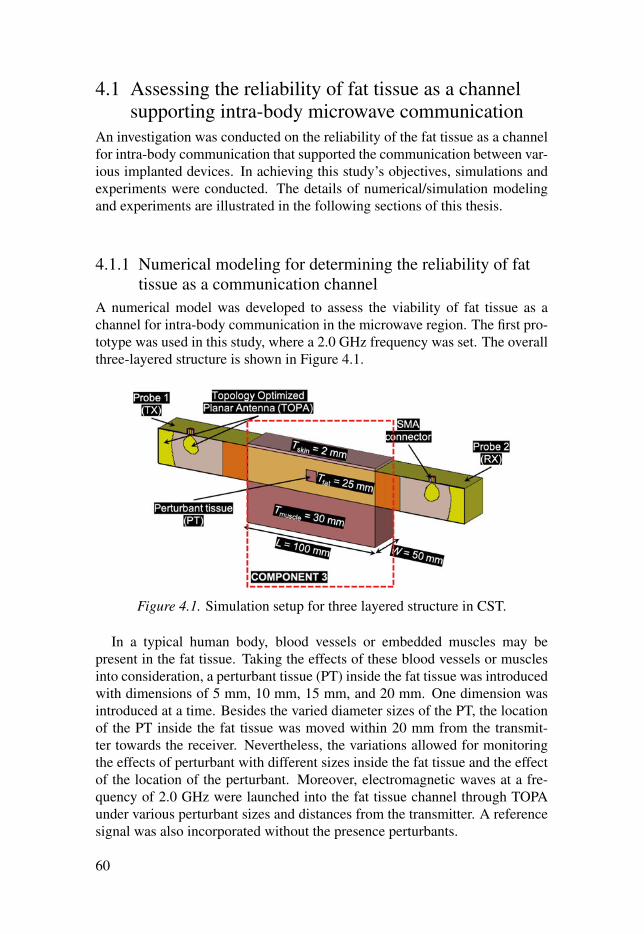
4.1 Assessing the reliability of fat tissue as a channelsupporting intra-body microwave communication
An investigation was conducted on the reliability of the fat tissue as a channelfor intra-body communication that supported the communication between var-ious implanted devices. In achieving this study’s objectives, simulations andexperiments were conducted. The details of numerical/simulation modelingand experiments are illustrated in the following sections of this thesis.
4.1.1 Numerical modeling for determining the reliability of fattissue as a communication channel
A numerical model was developed to assess the viability of fat tissue as achannel for intra-body communication in the microwave region. The first pro-totype was used in this study, where a 2.0 GHz frequency was set. The overallthree-layered structure is shown in Figure 4.1.
Figure 4.1. Simulation setup for three layered structure in CST.
In a typical human body, blood vessels or embedded muscles may bepresent in the fat tissue. Taking the effects of these blood vessels or musclesinto consideration, a perturbant tissue (PT) inside the fat tissue was introducedwith dimensions of 5 mm, 10 mm, 15 mm, and 20 mm. One dimension wasintroduced at a time. Besides the varied diameter sizes of the PT, the locationof the PT inside the fat tissue was moved within 20 mm from the transmit-ter towards the receiver. Nevertheless, the variations allowed for monitoringthe effects of perturbant with different sizes inside the fat tissue and the effectof the location of the perturbant. Moreover, electromagnetic waves at a fre-quency of 2.0 GHz were launched into the fat tissue channel through TOPAunder various perturbant sizes and distances from the transmitter. A referencesignal was also incorporated without the presence perturbants.
60

4.1.2 Experimental setup for determining the reliability of fattissue as a communication channel
To verify the results from the simulation setup, an experimental evaluation onthe equivalent phantom tissue was conducted, as shown in Figure 4.2. In thisevaluation, the same dimensions of skin, fat, and muscle tissues as the ones inthe simulation setup were used. To determine the similarity between the di-electric properties of human tissues and the phantom, repeated measurementswere carried out. An average frequency of 2.0 GHz was maintained, followedby the calculation of their differences using the ratio of the phantom to thehuman tissue. These differences are shown in Table 4.1.
Figure 4.2. Experimental setup of a complete setup and a magnified view of PT. PaperIV. Reprinted, with permission, from [65]. Copyright ©2017, IEEE.
Table 4.1. Dielectric properties of phantom in comparison with human tissues at 2.0GHz.
MaterialsParameters
Relative permittivity Loss tangentPhantom Human Diff.(%) Phantom Human Diff. (%)
Skin 36.50 38.57 –5.37 0.22 0.30 –26.67Fat 5.43 5.33 +1.88 0.16 0.15 +6.67Muscle 53.86 53.29 +1.07 0.21 0.25 –16.00
61

4.1.3 Results and discussion on the reliability of fat tissue as amicrowave communication channel
In this study, the influences of various interferences in the channel on |S21|were analyzed. The simulation results of the |S21| parameter upon the use ofPT of different sizes are illustrated in Figure 4.3. It can be seen from the figurethat in the comparison between small-sized PT and channel thicknesses, suchas 5 mm or 10 mm, no significant variation in the amplitude was found inthe S-parameter. However, when the ratio of PT with respect to the channelthickness was higher than 0.6, amplitude degradation could be observed. Thisdegradation indicated that compared to the channel thickness, small blockagesposed insignificant effects on the |S21| parameter. However, |S21| degradationsoccurred when PT size was comparable to the channel thickness.
1 1.2 1.4 1.6 1.8 2 2.2 2.4 2.6 2.8 3
Frequency (GHz)
-50
-45
-40
-35
-30
-25
-20
-15
-10
|S2
1| (d
B)
Reference (Fat channel)
Perturbant = 5 mm, Position = 20 mm
Perturbant = 5 mm, Position = 40 mm
Perturbant = 5 mm, Position = 60 mm
Perturbant = 5 mm, Position = 80 mm
Perturbant = 10 mm, Position = 20 mm
Perturbant = 10 mm, Position = 40 mm
Perturbant = 10 mm, Position = 60 mm
Perturbant = 10 mm, Position = 80 mm
2.0 GHz line
Perturbant = 15 mm, Position = 20 mm
Perturbant = 15 mm, Position = 40 mm
Perturbant = 15 mm, Position = 60 mm
Perturbant = 15 mm, Position = 80 mm
Perturbant = 20 mm, Position = 20 mm
Perturbant = 20 mm, Position = 40 mm
Perturbant = 20 mm, Position = 60 mm
Perturbant = 20 mm, Position = 80 mm
Figure 4.3. The |S21| parameters simulation results for various sized PT at differentlocations. Paper IV. Reprinted, with permission, from [65]. Copyright ©2017, IEEE.
62

A reference signal without the presence of PT was first obtained, followedby the incorporation of PT of various sizes inside the fat tissue. It was foundthat 10 mm PT did not affect the signal coupling irrespective of its position.In the case of 15 mm PT, a degradation of 4 dB/cm was observed in |S21| pa-rameter. Furthermore, experiments that were similar to the simulation wereconducted on PT of various sizes and different locations. Figure 4.4 showsthe comparison between the measured and simulated when 10 mm and 15 mmsize of PT was located at 40 mm distance from the transmitter in the fat tis-sue. Similar results as for the simulation results were observed. Based on thesimulated and measured results, it was indicated that compared to the homo-geneous thickness of the fat tissue, the fat tissue could be used as a reliablemedia for intra-body communication even when blockages of small size werepresent. Overall, the measurement results obtained from the investigation onthe |S21| parameter were in an agreement with the simulation results.
1 1.2 1.4 1.6 1.8 2 2.2 2.4 2.6 2.8 3
Frequency (GHz)
-50
-40
-30
-20
-10
0
Magnitude (
dB
)
S11
- Reference (S) S11
- 10 mm (S) S11
- 15 mm (S)
S21
- Reference (S) S21
- 10 mm (S) S21
- 15 mm (S)
S11
- Reference (M) S11
- 10 mm (M) S11
- 15 mm (M)
S21
- Reference (M) S21
- 10 mm (M) S21
- 15 mm (M)
Figure 4.4. Comparison between measured and simulated work for 10 mm and 15mm PT sizes at 40 mm PT position. Paper IV. Reprinted, with permission, from [65].Copyright ©2017, IEEE.
63

4.2 Effect of thickness inhomogeneity in fat tissue onintra-body microwave communication
The effects of inhomogeneity in the fat tissue were investigated when theywere used as a channel for intra-body microwave communication at a fre-quency of 2.45 GHz. The investigation on this aspect of the fat tissue wascrucial as the structure/thickness of fat tissue may vary among different in-dividuals. Besides, there is a wide range of fats inside the body, such as vis-ceral abdominal, epicardial, and periadventitial fats among others [66]. A con-cave and convex model of the three-layered skin-fat-muscle structure was alsodeveloped to observe the performance of the Fat-IBC when intra-body com-munication was involved. This investigation was followed by simulation andexperimental setups and the discussion of results in the following subsections.
4.2.1 Numerical modeling representing fat tissue thicknessdistribution inhomogeneity
The structure used for this study is shown in Figure 4.5. It is based on modelfrom Figure 4.1. The difference between the model and the structure could beseen from the curves in Component 3, which was the channel. Figure 4.5(a)illustrates a concave model, a concave structure positioned inwards from itsmiddle part, while Figure 4.5(b) presents a convex model, positioned outwardsfrom the middle part. For the concave model, the T fatmin value ranged from 5mm to 25.36 mm by 5 mm step. In the case of the convex model, the T fatmax
value ranged from 25.36 mm to 45 mm of fat thickness by 5 mm step. Thevariation of the thicknesses was based on an elliptical shape from the centerof the channel. Overall, the gap in both models ranged from 5 mm to 25 mmby 5 mm step from the probes. Similar to previous studies, investigation wasmade on the |S21| for these structures.
4.2.2 Experimental setup to study the effect of fat tissuethickness variation
In order to validate the results obtained from the simulation, a three-layeredtissue-equivalent phantom with two different models was developed in a sim-ilar method as the one used in the simulation work. The thickness of the fattissue for the concave model was set to be 20 mm, while the thickness of thecase of the convex model was set to be 35 mm with 10 mm gap for both cases.Notably, the primary difference between this study’s prototype and the pro-totype used in Section 4.1 was that the operating frequency of the probe wasfocused around 2.45 GHz (second probe’s prototype). The experimental setupis illustrated in Figure 4.6.
64

(a) Concave model.
(b) Convex model.
Figure 4.5. The models used for the numerical modeling studies. The simulation wasdone by varying two parameters, which are the fat thickness, T fat_min or T fat_max andthe gap. Paper V. Reprinted, with permission, from [38]. Copyright ©2018, IEEE.
4.2.3 Results and discussion to study the effect of fat tissuethickness variation
This subsection investigates on the vulnerability of the quality of the transmit-ting channel against the fat tissue thickness and the gap between the probesfor the concave and convex model. The results from the numerical modelingstudy in section 4.2.1 is shown in Figure 4.7. Notably, to achieve concise-ness in the results, only the observations on |S11| were incorporated. Overall,|S11| displayed a good result which was lower –12 dB. However, alterations inthe channel’s compatibility in terms of the gap distance would occur. As forthis case, the matching is good; thus, it is not the key parameter to observethe channel propagation behavior. Figure 4.7 shows the |S21|’s simulated re-sults for the concave and convex model. It could be seen that |S21| magnitude,specifically the concave model, gradually increased with the increase of fat
65

(a) Concave model. (b) Convex model.
Figure 4.6. Experimental setup based on phantom model for (a) concave (b) convex.The fat thickness for the concave model is 20 mm, and for the convex model is 35mm. gap for both model is 10 mm. Paper V. Reprinted, with permission, from [38].Copyright ©2018, IEEE.
thickness from 5 mm until its maximum value of 25.4 mm. Nevertheless, thegap posed a minor influence on the signal coupling. Moreover, |S21| wouldbe reduced until it reached a plateau for 30 mm of fat thickness and above.Meanwhile, no significant reduction was observed for the case of the convexmodel.
5 10 15 20 25.4 30 35 40 45
Fat thickness (mm)
-40
-35
-30
-25
-20
-15
-10
|S2
1| (d
B)
Gap = 0 mm
Gap = 5 mm
Gap = 10 mm
Gap = 15 mm
Gap = 20 mm
Gap = 25 mm
Convex modelConcave model
Reference thickness
Figure 4.7. Dependency of the transmission coefficient, |S21| with respect to the fatthickness (concave and convex model) and gap parameter at 2.45 GHz. Paper V.Reprinted, with permission, from [38]. Copyright ©2018, IEEE.
66

Figure 4.8 illustrates the comparison between simulation and experimenta-tion results based on phantom model for fat, concave, and convex channel interms of |S21|. It could be seen from this comparison that the variation in thefat thickness influenced the coupling coefficient |S21|. It was worthy to notethat the simulated and measured results were in an agreement with each other.Overall, the primary findings of this study are: Attenuation is less than 4 dBwhen the thickness is between 15 mm to 35 mm, gap does not affect the trans-mission properties and last but not the least when fat thickness is less than 15mm, attenuation in the signal is significant, however, not to the extent to breakcommunication link.
2 2.1 2.2 2.3 2.4 2.5 2.6 2.7 2.8
Frequency (GHz)
-25
-20
-15
-10
-5
0
|S2
1| (d
B)
Reference (simulation) Reference (measurement)
Convex model (simulation) Convex model (measurement)
Concave model (simulation) Concave model (measurement)
2.45 GHz line
Figure 4.8. A comparison of |S21| simulated and measured results for the fat channel,concave model and convex model at 2.45 GHz. Paper V Reprinted, with permission,from [38]. Copyright ©2018, IEEE.
67

4.3 Impact of blood vessels on intra-bodycommunication at 2.45 GHz
A thorough evaluation of the impact of blood vessel on the signal propagationin fat intra-body communication was conducted in this study. Three entities,namely size, position, and the number of blood vessels were analyzed. Fur-ther details and results from this analysis will be discussed in the followingsections.
4.3.1 Simulation model for assessment of the impact of bloodvessels on intra-body communication
As discussed in Section 4.2, the same probe prototypes were used in this study.Essentially, blood vessels can be classified into five types [67]. However, onlythree major types of blood vessels were considered in this study, namely arter-ies, veins, and arterioles, each having an average diameter of 4 mm, 5 mm, and30 μm respectively. Muscle tissue and copper rods were utilized to imitate thebehavior of blood vessels due to the analogy shown by these entities in termsof dielectric and conductivity behavior. The dielectric properties of compo-nents used in this experiment and its comparison with the human tissues areshown in Table 4.2.
Table 4.2. Relative permittivity and conductivity of human tissue and its comparisonwith the modeled components.
Tissue Human tissue Ex-vivo (measured) Similarity index (%)Skin 38 ± 2 40 ± 4 95Fat 5.3 ± 0.3 5.5 ± 0.5 96.36Muscle 53 ± 3 51 ± 5 96.22
(a) Relative permittivity (real part)
Tissue Human tissue Ex-vivo (measured) Similarity index (%)Skin 1.5 ± 0.1 1.4 ± 0.1 93.33Fat 0.1 ± 0.01 0.12 ± 0.01 83.33Muscle 1.7 ± 0.1 2.2 ± 0.2 77.27
(b) Conductivity (S/m)
68

It could be seen from the similarity index that the chosen materials pos-sessed similar conductivity and permittivity properties. In reality, the incorpo-ration of a blood vessel inside the tissues could be a longitudinal, transverse-vertical, or transverse-horizontal plane. Therefore, these scenarios were em-ulated and shown in Figure 4.9. The positions and number of blood vesselswere varied between the transmitter and the receiver. Vessels were with a stepsize of 20 mm were relocated for the simulation, with a distance of 10 mmto 90 mm from the transmitter. Following that, they were placed systemati-cally inside the tissues. The position of the blood vessels is indicated throughthe red dot in Figure 4.10. Figure 4.11 shows the view of the blood vesselsfrom the transmitter side. Images of the aforementioned figures illustrate theposition where the number of vessels increased from one to three.
(a) The longitudinal plane.
(b) The transverse-vertical plane.
(c) The transverse-horizontal plane.
Figure 4.9. Positioning of blood vessels inside fat tissue. Paper VI. Reprinted, withpermission, from [37]. Copyright ©2019, IEEE.
69

(a) The transverse-vertical view. (b) The transverse-horizontal view.
Figure 4.10. Blood vessel positioning. Paper VI. Reprinted, with permission, from[37]. Copyright ©2019, IEEE.
Figure 4.11. The longitudinal plane. Red dot represents blood vessels. Paper VI.Reprinted, with permission, from [37]. Copyright ©2019, IEEE.
70

4.3.2 Experimental demonstration for assessment of the impactof blood vessels on intra-body communication
A detailed experimental setup was materialized to observe the impact of bloodvessels on the fat tissues when fat tissues were used as a channel for intra-bodycommunication.
The fat and muscle for this experiment were extracted from a freshlyslaughtered porcine belly. Then, copper rods of various sizes based on theblood vessels were taken. Furthermore, a 3D printer with a dimension of 61mm × 230 mm × 63 mm was used. Cylindrical tubes with a wall thicknessof 0.4 mm and diameters of 2 mm, 4 mm, and 6 mm were constructed usingthe printer. To observe the |S21| parameter at those frequencies at the Fieldfoxmicrowave analyzer, frequencies ranging from 1 to 4 GHz were generated anddistributed to the three-layered structure by using the second probe’s proto-type. All the experiments were conducted under 22° C surrounding tempera-ture. The overall experimental setup is illustrated in Figure 4.12.
4.3.3 Results and discussion on the assessment of the impact ofblood vessels as a channel for intra-body communication
This study focused on the effects of various types of blood vessels, which wereextracted from copper and porcine belly muscle on the transmission channel.Figure 4.13 illustrates the |S21| parameter results for the simulated and mea-sured setup conducted on the muscle rod, while Figure 4.14 presents the |S21|parameter for the copper rod. This study’s system was tested in terms of thethree diameters of blood vessels, namely 2 mm, 4 mm, and 6 mm.
It could be seen from Figure 4.13 that the increase in the number of musclerod was inversely related to the amplitude of |S21|. This relation indicated thatthe signal strength reduced with the increase in the number of muscle rods,which was applied to all diameters. However, a more prominent decrease inthe magnitude for |S21| could be seen in a 6 mm diameter muscle, which wasfrom 0.2 to 1.6 dB. Following a similar trend, the results in Figure 4.13 areshown to be completely similar to the results in Figure 4.14, with the use ofcopper rod as an exception. Based on these figures, a higher signal-couplingeffect was observed when the copper rod was placed near the skin comparedto its placement on the top of the muscle. This effect was due to the differencebetween the permittivity of skin, where the skin is thinner with less permittiv-ity, and the muscle’s permittivity.
71

(a) The longitudinal plane view.
(b) The transverse-vertical plane view. (c) The transverse-horizontal plane view.
Figure 4.12. Experimental setup. Paper VI. Reprinted, with permission, from [37].Copyright ©2019, IEEE.
It is shown in Figure 4.15 that the occurrence of the electric field was dueto the blood vessels in longitudinal plane. The simulations for all the caseswere conducted where the diameters of the vessels of the muscle and copperrods amounted to 2 mm, 4 mm, and 6 mm. However, only one case of 6 mmmuscle and copper rods was present (see Figure 4.15) when the blood vesselswere aligned at the top of the muscle and the bottom of the skin.
Similar to the results in Figure 4.13 and Figure 4.14, the results of thetransverse-vertical and transverse-horizontal plane were observed. However,to achieve conciseness of results, only the observations were incorporated,where the vessel was placed vertically. It was suggested that |S21| decreasedwith the increase in the number of rods from 1 to 3. Furthermore, copper rods
72

+Tfat/4
0 (center) -Tfat/4
Position (mm)
-50
-40
-30
-20S
21 (
dB
)
1 muscle rod (S) 2 muscle rods (S) 3 muscle rods (S)
(a) Diameter = 2 mm (simulated)
+Tfat/4
0 (center) -Tfat/4
Position (mm)
-50
-40
-30
-20
S2
1 (
dB
)
1 muscle rod (M) 2 muscle rods (M) 3 muscle rods (M)
(b) Diameter = 2 mm (measured)
+Tfat/4
0 (center) -Tfat/4
Position (mm)
-50
-40
-30
-20
S21 (
dB
)
1 muscle rod (S) 2 muscle rods (S) 3 muscle rods (S)
(c) Diameter = 4 mm (simulated)
+Tfat/4
0 (center) -Tfat/4
Position (mm)
-50
-40
-30
-20
S2
1 (
dB
)
1 muscle rod (M) 2 muscle rods (M) 3 muscle rods (M)
(d) Diameter = 4 mm (measured)
+Tfat/4
0 (center) -Tfat/4
Position (mm)
-50
-40
-30
-20
S21 (
dB
)
1 muscle rod (S) 2 muscle rods (S) 3 muscle rods (S)
(e) Diameter = 6 mm (simulated)
+Tfat/4
0 (center) -Tfat/4
Position (mm)
-50
-40
-30
-20S
21 (
dB
)
1 muscle rod (M) 2 muscle rods (M) 3 muscle rods (M)
(f) Diameter = 6 mm (measured)
Figure 4.13. Simulated and experimental results for |S21| parameter for 60 mm longmuscle tissue in a longitudinal plane. (a), (c), (e) is simulated results for 2 mm, 4 mmand 6 mm diameter, respectively and (b), (d) and (f) is measured results for 2 mm,4 mm and 6 mm diameter, respectively. Paper VI. Reprinted, with permission, from[37]. Copyright ©2019, IEEE.
led to further degradation compared to muscle rods. The use of the musclerod with three vessels of 6 mm diameter resulted in 5.13 dB of signal cou-pling loss in the measured result and 5.11 dB of signal coupling loss in thesimulated results. Nevertheless, both results were in an agreement with eachother. When the copper rod was tested with three vessels of 6 mm diame-ter, the signal coupling loss in the experiment amounted to 17.13 dB, while14.31 dB of signal coupling loss was reported in the simulated case. Thesesignificant losses were primarily attributed to the higher reflectivity in coppermaterial. As the rods were placed in the vertical position of the transmitter, or-thogonal propagation was observed towards the line of transmission, resultingin prominent reflections. Notably, a stark transverse electric field disruptioninside the transmitting media contributed to signal propagation loss, leading todegradation. The dielectric characteristics of blood vessels were comparableto the characteristics of muscles, where less significant propagation degrada-tions took place.
73
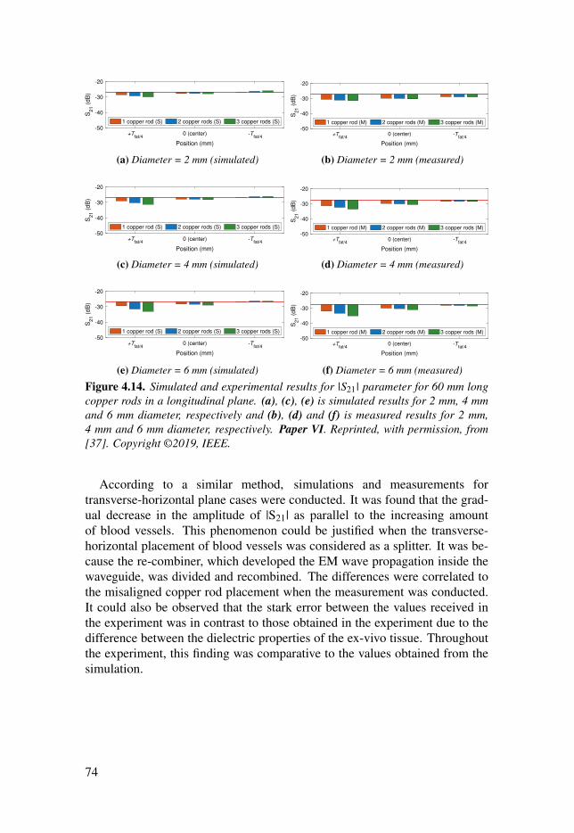
+Tfat/4
0 (center) -Tfat/4
Position (mm)
-50
-40
-30
-20S
21 (
dB
)
1 copper rod (S) 2 copper rods (S) 3 copper rods (S)
(a) Diameter = 2 mm (simulated)
+Tfat/4
0 (center) -Tfat/4
Position (mm)
-50
-40
-30
-20
S2
1 (
dB
)
1 copper rod (M) 2 copper rods (M) 3 copper rods (M)
(b) Diameter = 2 mm (measured)
+Tfat/4
0 (center) -Tfat/4
Position (mm)
-50
-40
-30
-20
S21 (
dB
)
1 copper rod (S) 2 copper rods (S) 3 copper rods (S)
(c) Diameter = 4 mm (simulated)
+Tfat/4
0 (center) -Tfat/4
Position (mm)
-50
-40
-30
-20
S2
1 (
dB
)
1 copper rod (M) 2 copper rods (M) 3 copper rods (M)
(d) Diameter = 4 mm (measured)
+Tfat/4
0 (center) -Tfat/4
Position (mm)
-50
-40
-30
-20
S21 (
dB
)
1 copper rod (S) 2 copper rods (S) 3 copper rods (S)
(e) Diameter = 6 mm (simulated)
+Tfat/4
0 (center) -Tfat/4
Position (mm)
-50
-40
-30
-20S
21 (
dB
)
1 copper rod (M) 2 copper rods (M) 3 copper rods (M)
(f) Diameter = 6 mm (measured)
Figure 4.14. Simulated and experimental results for |S21| parameter for 60 mm longcopper rods in a longitudinal plane. (a), (c), (e) is simulated results for 2 mm, 4 mmand 6 mm diameter, respectively and (b), (d) and (f) is measured results for 2 mm,4 mm and 6 mm diameter, respectively. Paper VI. Reprinted, with permission, from[37]. Copyright ©2019, IEEE.
According to a similar method, simulations and measurements fortransverse-horizontal plane cases were conducted. It was found that the grad-ual decrease in the amplitude of |S21| as parallel to the increasing amountof blood vessels. This phenomenon could be justified when the transverse-horizontal placement of blood vessels was considered as a splitter. It was be-cause the re-combiner, which developed the EM wave propagation inside thewaveguide, was divided and recombined. The differences were correlated tothe misaligned copper rod placement when the measurement was conducted.It could also be observed that the stark error between the values received inthe experiment was in contrast to those obtained in the experiment due to thedifference between the dielectric properties of the ex-vivo tissue. Throughoutthe experiment, this finding was comparative to the values obtained from thesimulation.
74

(a) Muscle rod placed at +T fat/4. (b) Muscle rod placed at −T fat/4.
(c) Copper rod placed at +T fat/4. (d) Copper rod placed at −T fat/4.
Figure 4.15. Electric field for the case of three 6 mm diameter blood vessels in longi-tudinal plane. (a), (b) muscle rod placed at +T fat/4 and −T fat/4 location, respectively(c) and (d) copper rod placed at +T fat/4 and +T fat/4 location, respectively. Paper VI.Reprinted, with permission, from [37]. Copyright ©2019, IEEE.
It could be summarized that in respect of the longitudinal plane, the place-ment of muscle rod at +T fat/4 resulted in a more prominent signal coupling ef-fect due to the significant total average loss for both materials. To illustrate thissignal was highly attenuated when the copper rod was placed in a transverse-vertical position. Meanwhile, when placed in the transverse-horizontal plane,there was a difference of 3.42 dB and 1.91 dB in muscle and copper rods’readings, which was relative to the reference value of the fat channel. Fur-thermore, the least prominent effect was posed on the signal coupling due tothe presence of the blood vessel(s). Nevertheless, to achieve conciseness ofthe results, the complete experimental and simulated summary of |S21| resultsunder all situations is illustrated in the tabulated forms, as shown in Table 4.3.
75

Table 4.3. Comparison of simulated and measured transmission loss (|S21|), averagewith respect to the fat channel [Average(Reference - |S21|)]. Paper VI. Reprinted, withpermission, from [37]. Copyright ©2019, IEEE.
Vessel(s) No. ofVessel(s)
Average |S21| (dB) Measured (Simulated)Longitudinal
PlaneTransverse-vertical
PlaneTransverse-horizontal
PlaneMuscle Copper Muscle Copper Muscle Copper
2 mm 11.17
(0.62)2.39
(0.86)0.83
(0.81)1.51
(2.51)1.79
(0.57)1.50
(0.58)
21.44
(0.67)2.64
(0.91)0.91
(0.88)4.53
(3.35)1.87
(0.65)1.52
(0.70)
32.47
(0.75)2.90
(1.09)1.05
(1.03)9.12
(7.97)1.92
(0.69)1.52
(1.12)
Average1.70
(0.68)2.64
(0.96)2.12
(2.09)5.44
(3.20)1.86
(0.64)1.51
(0.80)
4 mm 11.20
(0.93)2.44
(1.10)1.81
(1.79)7.56
(3.21)1.90
(0.68)1.68
(0.67)
21.68
(1.14)2.86
(1.33)2.07
(2.04)9.47
(5.09)2.15
(0.91)1.61
(0.88)
32.65
(1.46)3.45
(1.70)2.67
(2.66)15.08
(11.70)2.31
(1.10)1.61
(1.74)
Average1.84
(1.17)2.92
(1.37)2.53
(2.50)15.08
(11.70)2.12
(0.90)1.64
(1.08)
6 mm 12.26
(1.66)2.62
(1.36)3.71
(3.68)7.25
(3.87)2.17
(0.93)1.38
(0.67)
22.98
(2.11)3.24
(1.90)4.59
(4.58)11.15(7.13)
2.76(1.53)
1.56(1.34)
34.50
(2.96)4.15
(2.60)5.13
(5.11)17.13
(14.31)3.42
(2.20)1.91
(3.94)
Average3.25
(2.24)3.33
(1.95)2.95
(2.93)13.77
(11.33)2.79
(1.56)1.62
(1.99)
76

4.4 Effect of misalignment in fat tissue on intra-bodymicrowave communication
In this paper, the numerical modeling and experimental validation of the sig-nal path loss at 5.8 GHz are presented within the framework of fat-intrabodycommunication (Fat-IBC). To propagate information from one implanted de-vice to another, the third probe’s prototype was used. The selection of thiswaveguide probe was due to its capability to direct the radiation through thefat tissue. Notably, this study not only determined the feasibility of implanteddevices at 5.8 GHz frequency, it also identified the effects of dynamic bodymovements.
4.4.1 Simulation and numerical modeling of effect of probemisalignment in fat tissue
To investigate the effects of misalignment between the transmitting and re-ceiving probe, numerical modeling and simulation were conducted. In thisphase, two types of experiments were performed. In the first experiment, thetransmitting and receiving probes were placed vertically and horizontally. Thetransmitter was also aligned at four positions, namely up, down, right, andleft as shown in Figure 4.16(a). This was followed by the second experimentwhere a 90° rotation of transmitter was done before both transmitter and re-ceiver were rotated at the same angle. Furthermore, a homogeneous structureof skin, fat, and muscle was developed, where the fat was positioned betweenskin and muscle. The dimension of the structure was set to be 180 mm × 80mm, with 100 mm of distance between the probes. Moreover, a free spacemedium outside the skin and consider the radiation boundary condition werealso taken into account. Figure 4.16(b) illustrates special case when transmit-ting probe was placed on the top of the muscle, while the receiving probe wasplaced at the center of the fat.
77

(a) Cross-view shows misalignment scenarios of the probe.
(b) A specific example of the alignment.
Figure 4.16. Numerical modeling setup (a) misalignment scenarios of the probe (b) aspecific example. Paper III. Adapted, from [61].
78

4.4.2 Results and discussion on effect of probe misalignment infat tissue
In this section, the results of two experiments discussed in Section 4.4.1,namely the misalignment and cross-polarization cases, are elaborated. Fig-ure 4.17 displays the simulation results for ex-vivo |S11| and |S21| upon thechange of the location of the TX probe in the fat tissue. It also presents theinfluence of upright displacement of the probes on the signal coupling throughthe fat-channel. To be specific, Figure 4.17(a) shows that the TX probe skinwas dislocated upward or downward to the muscle tissue. However, thesedislocations posed negligible effects on |S11| parameter. On the contrary, Fig-ure 4.17(b) illustrates that the TX probe was displaced downwards to the mus-cle, posing a significant influence on |S11| parameter. It was concluded thatthe vertical displacement of the probe is formed through a nearly 3 dB and 1dB increase in the channel insertion loss when the probe is dislocated upwardsand downwards, respectively.
3 3.5 4 4.5 5 5.5 6 6.5 7 7.5 8
Frequency (GHz)
-50
-40
-30
-20
-10
0
|S1
1| (d
B)
20 mm - Center
40 mm - Center
60 mm - Center
80 mm - Center
100 mm - Center
20 mm - Up
40 mm - Up
60 mm - Up
80 mm - Up
100 mm - Up
20 mm - Down
40 mm - Down
60 mm - Down
80 mm - Down
100 mm - Down
(a) Reflection coefficient, |S11|.
3 3.5 4 4.5 5 5.5 6 6.5 7 7.5 8
Frequency (GHz)
-50
-40
-30
-20
-10
0
|S2
1| (d
B)
20 mm - Center
40 mm - Center
60 mm - Center
80 mm - Center
100 mm - Center
20 mm - Up
40 mm - Up
60 mm - Up
80 mm - Up
100 mm - Up
20 mm - Down
40 mm - Down
60 mm - Down
80 mm - Down
100 mm - Down
(b) Transmission coefficient, |S21|.Figure 4.17. Simulated results of |S11| and |S21| when TX probe is placed in thecenter, below the skin, and on top of the muscle. The RX is placed in the center of thefat tissue. Paper III. Adapted, from [61].
Figure 4.18a displays the simulated results for ex-vivo of |S11| and |S21|parameter when the location of the TX probe in the fat tissue is changed. Fur-thermore, it also indicates that the probe’s horizontal dislocation affects signalcoupling. Figure 4.18(a) demonstrates that the horizontal displacement posesno essential impact on the probe’s reflection coefficient. Additionally, the re-sults of the transmission coefficient indicate that, compared to the referencecase (see Figure 4.18(b)), 15 mm of horizontal displacement of the insertionloss increases by 2 dB at maximum.
79

3 3.5 4 4.5 5 5.5 6 6.5 7 7.5 8
Frequency (GHz)
-50
-40
-30
-20
-10
0|S
11| (d
B)
20 mm - Center
40 mm - Center
60 mm - Center
80 mm - Center
100 mm - Center
20 mm - Left
40 mm - Left
60 mm - Left
80 mm - Left
100 mm - Left
20 mm - Right
40 mm - Right
60 mm - Right
80 mm - Right
100 mm - Right
(a) Reflection coefficient, |S11|.
3 3.5 4 4.5 5 5.5 6 6.5 7 7.5 8
Frequency (GHz)
-50
-40
-30
-20
-10
0
|S2
1| (d
B)
20 mm - Center
40 mm - Center
60 mm - Center
80 mm - Center
100 mm - Center
20 mm - Left
40 mm - Left
60 mm - Left
80 mm - Left
100 mm - Left
20 mm - Right
40 mm - Right
60 mm - Right
80 mm - Right
100 mm - Right
(b) Transmission coefficient, |S21|.Figure 4.18. Simulated results of |S11| and |S21| when TX probe is placed in the center,left side, and on the right side where as RX is centered in the fat tissue. Paper III.Adapted, from [61].
The results of the second experiment, which has been discussed in Sec-tion 4.4.1, are elaborated in this section. In respect of the 90° rotation of thetransmitted probe in the ex-vivo porcine tissue, the results of it are shown inFigure 4.19. It could be seen from this figure that, at 100 mm channel length,the |S21| for the simulation and measurement was reduced by 35 dB and 38.4dB respectively in terms of its reference (Type D model, as discussed in Chap-ter 3).
3 3.5 4 4.5 5 5.5 6 6.5 7 7.5 8
Frequency (GHz)
-80
-60
-40
-20
0
|S21| (d
B)
Type D (Simulation) Type D (Measurement)
Type D 90° rotated (Simulation) Type D 90° rotated (Measurement)
Figure 4.19. TX probe is 90° rotated for Type D: Transmission coefficient, |S21| dBfor ex-vivo tissue. Paper III. Adapted, from [61].
Similar to the phenomena of parallel plate transmission lines, rotating thetransmitting and receiving probe could facilitate the influence of horizontallypolarized electric field in the fat channel. Meanwhile, in the case of the rota-tion of the transmitting and receiving probes at 90° imposing horizontal fieldin the channel for IBC, the results are illustrated in Figure 4.20. Based onFigure 4.19, it could be seen that the presented scenario had good compati-
80

bility with the fat channel as the |S11|’s value was lower than –15 dB. It wassuggested from |S21| parameter at 5.8 GHz that the variation of the resultswas not significant with the rotation of the probe. Overall, a flat transmissioncoefficient was found.
3 3.5 4 4.5 5 5.5 6 6.5 7 7.5 8
Frequency (GHz)
-50
-40
-30
-20
-10
0
|S1
1| (d
B)
20 mm - 0° (normal)
40 mm - 0° (normal)
60 mm - 0° (normal)
80 mm - 0° (normal)
100 mm - 0° (normal)
20 mm - 90° (rotated)
40 mm - 90° (rotated)
60 mm - 90° (rotated)
80 mm - 90° (rotated)
100 mm - 90° (rotated)
(a) Reflection coefficient, |S11|.
3 3.5 4 4.5 5 5.5 6 6.5 7 7.5 8
Frequency (GHz)
-50
-40
-30
-20
-10
0
|S2
1| (d
B)
20 mm - 0° (normal)
40 mm - 0° (normal)
60 mm - 0° (normal)
80 mm - 0° (normal)
100 mm - 0° (normal)
20 mm - 90° (rotated)
40 mm - 90° (rotated)
60 mm - 90° (rotated)
80 mm - 90° (rotated)
100 mm - 90° (rotated)
(b) Transmission coefficient, |S21|.Figure 4.20. Evaluating |S11| and |S21| parameters for the case when transmittingand receiving probes are rotated 90°. Paper III. Adapted, from [61].
Overall, it could be concluded that the increase in the fat thickness resultsin lower path loss in channel transmission. The path polarization of the probeposed a negative impact on the signal coupling, leading to the reduction inthe received power by approximately –38.4 dB in measurement and –35 dB insimulation. Last but not least, the vertical misalignment between two probesdid not pose a significant impact on the signal coupling.
81


5. Packet transmission and perturbationsensing in the Fat-IBC
The potential factors affecting the reliability of a Fat-IBC channel have beendiscussed in Chapter 4 as a part of the preliminary study on the feasibility ofthis approach. Investigations were also conducted to measure the reliabilityof the channel, the effects of blood vessel orientation, placement, and thecommunication link. This was followed by experiments on the effects ofinhomogeneity fat tissue thickness on communication. In this chapter, weaddress the issue by sending the data packet transmission through fat tissuesupporting wireless connectivity of intra-body devices. Notably, implanteddevices, such as cardiac pacemakers, neuro-prosthetics, and cardiovertersincreased the demand for bandwidth due to the high data rate communicationrequired by the devices [68]. Moreover, fat tissues were used in this study asthe medium of microwave communication to transfer and receive a packet.This process involved real data or health information and determined thedata packet reception. The numerical modeling, experimental setup, energyconsumption, and the results of this part of the study are discussed in thefollowing sections.
• Section 5.1: Paper VII presents the analysis of Data Packet Reception(PRR), which involved measurement of 2.0 GHz to evaluate the effects oftransmission interference on Fat-IBC transmission.
• Section 5.2: Paper IV presents the investigation on the possibility of theuse of a fat-intra-body communication technique for sensing.
To obtain the experimental data in Paper VII, the measurement setup wassimilar to the experimental setup shown in Chapter 2 (Section 3), with changesperformed in Component 1 and 2. To be specific, modifications were per-formed in Component 1, where the TX and RX probes were connected to aUSRP B200 SDR for packets measurement setups. To measure the RSS, theRX was connected with the FieldFox Handheld RF and Microwave Analyzer.
83

5.1 Data packet transmission via fat tissueAn investigation was conducted to prove that the transfer of data packets viafat tissues is possible. Accordingly, R-band frequencies which covered theISM band of 2.4 GHz were selected [69]. The methods and materials used inthis study are presented in the following sections.
5.1.1 Experimental details of data packet transmission via fattissue
The investigation on low power wireless personal area networks was accordingto the IEEE 802.15.4 standard. The specifications implemented in this investi-gation are presented in Table 5.1. As the operation of a standard-compliantIEEE 802.15.4 transceiver was impossible at 2.0 GHz, a software-defined802.15.4 transceiver was used as an alternative.
Table 5.1. The used IEEE 802.15.4 standard specifications used.Parameter ValueFrequency 2.0 GHzNo. of channels 16Channel bandwidth 5 MHzModulation scheme Offset Quadrature Phase Shift KeyingData rate 250 kbpsSpread spectrum technique Direct Sequence Spread SpectrumData mapping 4 bit mapping to 32 bit pseudo-random sequenceModulated signal bandwidth 2 MHz
The received signal strength (RSS) setup and packet measurement setupare shown in Figure 5.1. To be specific, a GNU radio-based IEEE 802.15.4transceiver was used, which also included the use of a USRP B200 software-defined radio (SDR) [70]. Two independent experiments were conducted forthe measurement of RSS and data packet reception. As a result, the setup forRSS is presented in Figure 5.1(a), while the setup for data packet reception isillustrated in Figure 5.1(b). This is followed by the overall practical setup inFigure 5.1(c). It could be seen from Figure 5.1(a) that probe 1 was connectedto the computer through SDR USRP B200, which transmitted the signal in thefat tissue. The signal then traveled to the receiving probe 2, which was con-nected to the Fieldfox microwave analyzer used to record the signal strength.Meanwhile, Figure 5.1(b) configuration indicates that both the transmittingand receiving probes were connected to the SDR USRP B200, enabling theacquirement of data packets and the reception rate measurement.
84

(a) Illustrative diagram showing the setup to measure the Received Signal Strength (RSS).
(b) Illustrative diagram showing the setup to measure the data packet reception.
(c) Ex-vivo and phantom experimental setup.
Figure 5.1. Two separate measurement setups to characterize the RSS and data packetreception, and experimentation setup consisting of skin, fat, and muscle layer. PaperVII. Reprinted, with permission, from [39]. Copyright ©2017, IEEE.
85
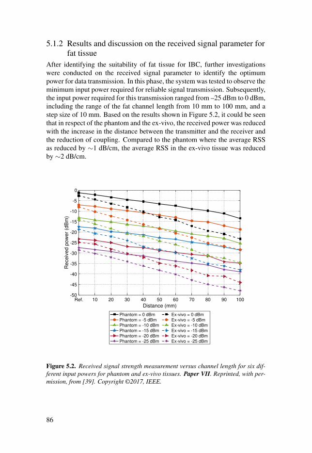
5.1.2 Results and discussion on the received signal parameter forfat tissue
After identifying the suitability of fat tissue for IBC, further investigationswere conducted on the received signal parameter to identify the optimumpower for data transmission. In this phase, the system was tested to observe theminimum input power required for reliable signal transmission. Subsequently,the input power required for this transmission ranged from –25 dBm to 0 dBm,including the range of the fat channel length from 10 mm to 100 mm, and astep size of 10 mm. Based on the results shown in Figure 5.2, it could be seenthat in respect of the phantom and the ex-vivo, the received power was reducedwith the increase in the distance between the transmitter and the receiver andthe reduction of coupling. Compared to the phantom where the average RSSas reduced by ∼1 dB/cm, the average RSS in the ex-vivo tissue was reducedby ∼2 dB/cm.
Ref. 10 20 30 40 50 60 70 80 90 100
Distance (mm)
-50
-45
-40
-35
-30
-25
-20
-15
-10
-5
0
Receiv
ed p
ow
er
(dB
m)
Phantom = 0 dBmPhantom = -5 dBmPhantom = -10 dBmPhantom = -15 dBmPhantom = -20 dBmPhantom = -25 dBm
Ex-vivo = 0 dBmEx-vivo = -5 dBmEx-vivo = -10 dBmEx-vivo = -15 dBmEx-vivo = -20 dBmEx-vivo = -25 dBm
Figure 5.2. Received signal strength measurement versus channel length for six dif-ferent input powers for phantom and ex-vivo tissues. Paper VII. Reprinted, with per-mission, from [39]. Copyright ©2017, IEEE.
86

5.1.3 Packet reception with respect to transmitted power forFat-IBC
In observing the data packet reception for phantom and ex-vivo tissue, thelength of the fat tissue was set to range from 20 mm to 100 mm, with a step sizeof 20 mm. The transmitted power for Fat-IBC was also set to range from –25dB to 0 dB. As a result, it could be seen from Figure 5.3 that the approximatepercentage of successful packet reception for phantom and ex-vivo tissue was96 %. It was also suggested that the power could be further reduced from–25 dB to determine the lowest power which was sufficient for good packetreception. –25 dBm was selected as the lower range since it corresponds tothe lowest output power of many low-power transceivers. Overall, fat tissuewas proven to be a reliable and promising channel for IBC.
Ref. 20 40 60 80 100
Distance (mm)
0
20
40
60
80
100
Packet re
ceiv
ed (
%)
Phantom = 0 dBm Phantom = -5 dBm Phantom = -15 dBm Phantom = -25 dBm
Ex-vivo = 0 dBm Ex-vivo = -5 dBm Ex-vivo = -15 dBm Ex-vivo = -25 dBm
Figure 5.3. Percentage of packet reception versus channel length for six differentinput powers for phantom and ex-vivo tissues. Paper VII. Reprinted, with permission,from [39]. Copyright ©2017, IEEE.
87

5.2 Sensing applications of Fat-IBCIn Chapter 4 and Chapter 5, it was indicated through the conducted simula-tions and experiments that fat tissue is reliable for data rate IBC even at lowpower consumption. A side-effect of this novel communication technique isits ability to monitor changes in the properties of the communication channel.Such changes could help with early detection of diseases, such as lymphedemaor tumour relapse. It could be seen in Section 4.1 that the fat channel could beused for communication even under the presence of a perturbant, for example,a cancerous tissue. This situation was possible if the thickness of perturbanttissue (PT) was lower than 60 % of the thickness of the fat tissue, as shownin Figure 4.3. However, the presence of PT reduced the signal strength inthe communication channel between the transmitter and the receiver. Thisattribute could be used to identify the hindrance occurring due to embeddedmuscle(s) or tumor(s). It could also be used in tumor detection as the increasein tumor size would result in dramatic changes in communication properties.
The relationship between tumor size and the received signal strength isshown in Figure 5.4. Based on the figure, the blue line indicates the behaviorof the received coupling when the PT was present and phantom measurementswere conducted. Meanwhile, the orange line indicates the behavior when sim-ulations were conducted on PT with ex-vivo dielectric properties. Overall, adifference of approximately 6 dB from the reference value and PT was 8 mmin radius mainly due to the different materials used to emulate the fat tissue.Nevertheless, similar trend was observed overall. Therefore, it could be con-cluded that with the increase in tumor size, the signal strength would decrease.This feature could be used for tumor detection.
Ref. 1 2 3 4 5 6 7 8 9 10
Perturbant radius (mm)
-32
-30
-28
-26
-24
-22
-20
-18
-16
|S2
1| (d
B)
Cube (Phantom measured results at 2.0 GHz)
Sphere (Ex-vivo simulated results at 2.45 GHz)
Figure 5.4. The comparison of perturbant relationship with respect to with the trans-mission coefficient S21.
88

6. Summary of the appended papers
This chapter presents the summary, scientific contribution, key findings, andpersonal contributions of the papers that are part of the thesis.
6.1 Fat-IBC characterizationThis section summarizes three of the papers that deal with the characterizationof the Fat-IBC, namely Papers I–III.
6.1.1 Paper I – Intra-body microwave communication throughadipose tissue
Noor Badariah Asan, Daniel Noreland, Emadeldeen Hassan, Syaiful Redzwan MohdShah, Anders Rydberg, Taco J. Blokhuis, Per-Ola Carlsson, Thiemo Voigt, RobinAugustine. 2017. “Intra-body microwave communication through adipose tissue,”Healthcare Technology Letters, 4(4), pp. 115–121.
SummaryIn this paper, we introduce a preliminary study on the impact (or influence)that layers of fat and muscle tissues with different thicknesses will have onthe performance of the Fat-IBC channel. We used R-band frequencies sincethey overlap with the industrial, scientific, and medical (ISM) radio bands. Thechannel model proposed in the context of human tissues is electromagnetically(EM) simulated and then validated by using the tissue-equivalent phantom andex-vivo measurements. The measurements are juxtaposed accordingly withnumerical modeling. At 2.0 GHz, we obtained a path loss for the phantomof ∼1 dB/cm and ∼2 dB/cm for ex-vivo, respectively. We estimated the pathloss in human tissue to be around 1.5 dB/cm as the dielectric losses in humanadipose tissue are almost half of the ex-vivo tissue. This paper is our first stepin using the adipose tissue as a transmission medium, and it shows that adiposetissue is feasible for low-loss microwave communication.
Contribution and key findings• A novel method of using fat tissue as the microwave transmission
channel is successfully demonstrated in tissue-equivalent phantomand ex-vivo porcine tissues.
89

• Fat tissue displays superior performance in comparison to muscle tis-sue in the context of a low loss communication channel.
• Thicker fat tissue gives lower loss in signal transmission.• Variation of muscle thickness has minimal impact on signal transmis-
sion.• At 2.0 GHz, losses of ∼1 dB/cm and ∼2 dB/cm were observed for
phantom measurements and ex-vivo measurements, respectively.• For human fat tissue, an attenuation of approximately ∼1.5 dB/cm has
been estimated.
Personal contributionsI planned and performed the simulations and experiments, as well as doing theanalysis of the data. The probe used was jointly developed. I did major part ofwriting the manuscript.
6.1.2 Paper II – Characterization of the fat channel for intra-bodycommunication at R-band frequencies
Noor Badariah Asan, Emadeldeen Hassan, Jacob Velander, Syaiful Redzwan MohdShah, Daniel Noreland, Taco J. Blokhuis, Eddie Wadbro, Martin Berggren, ThiemoVoigt, and Robin Augustine. 2018. “Characterization of the Fat Channel for Intra-Body Communication at R-Band Frequencies,” Sensors, 18(9): 2752.
SummaryThis paper demonstrates further the characterization of the fat tissue as amedium for communication between implanted devices, specifically in R-bandfrequencies. We designed the fat channel consisting of the skin, fat, and mus-cle layers according to the simplified anatomically-tailored model of the hu-man body. We introduced a novel probe that is excellently matched to radiatethrough the fat tissue at R-band frequencies (i.e., 1.7–2.6 GHz). In order toassess the fat channel path loss, we observe the channel transmission coeffi-cient, S21 across the R-band frequencies. An extensive numerical modelingwas done and validated via phantom and ex-vivo porcine tissue experimenta-tions. The results of the fat channel characterization display ∼0.7 dB/cm and∼1.9 dB/cm propagation path losses for phantom and ex-vivo porcine tissue,respectively. Due to the material used in the development of the probe and alsothe phantom and ex-vivo tissue, the path loss is slightly different from Paper I.We also perform a comparative study between the fat channel and the parallelplate waveguide structure by replacing the skin and muscle layers with copperplates. The result shows that the fat channel behaves as a waveguide structure.The experimentations yield an excellent agreement with the simulations. Theresults in this paper sufficiently denote the potential and possibility of fat tis-sue utilization as a mechanism of communication in the purpose of high datarate intra-body networks, explained in Paper VII accordingly.
90

Contribution and key findings• An evaluation of the capacity of fat tissue as a novel medium for intra-
body communication at R-band frequencies (1.7–2.6 GHz).• Successful development and fabrication of a novel probe equipped
with a topology-optimized planar antenna (TOPA), providing an ex-cellent signal match to fat tissue.
• The medium for communication depicts a parallel plate transmissionchannel consisting of the fat layer with low dielectric permittivity,sandwiched between two layers (skin and muscle) with high dielectricpermittivity.
• Skin and muscle tissues function as the conducting layers, wherebytheir high permittivity and conductivity compared to the fat tissue in-fluence tremendously in affecting the transmission channel via the fattissue. Such observation is due to the microwave signal being con-fined in the fat tissue.
• Fat channel characterization yielded ∼0.7 dB/cm and ∼1.9 dB/cmpath losses for phantom and ex-vivo porcine tissues, respectively.
Personal contributionsI planned and performed the simulations and experiments, as well as doing theanalysis of the data. I did major part of writing the manuscript.
6.1.3 Paper III – Fat-Intra Body Communication at 5.8 GHzIncluding Impacts of Dynamic Body Movements
Noor Badariah Asan, Emadeldeen Hassan, Mauricio D. Perez, Laya Joseph, MartinBerggren, Thiemo Voigt, and Robin Augustine. 2019. “Fat-Intra Body Communica-tion at 5.8 GHz Including Impacts of Dynamic Body Movements,” Manuscript.
SummaryIn this paper, numerical modeling and experimental validation of the signalpath loss at 5.8 GHz is presented within the framework of fat-intrabody com-munication (Fat-IBC). In order to propagate information from one implanteddevice to another, we proposed a topology-optimized waveguide probe whichhas the capability to direct radiation through the fat tissue. This study not onlyaccesses the feasibility of implanted devices, their performance at 5.8 GHzfrequency but also includes the effect of dynamic body movements. Our re-sults show that by changing the channel length from 20 mm to 100 mm andobserved that an average path loss of as low as 1.4 dB/cm at 5.8 GHz. Inorder to study the impact of misalignment, we first assumed that the probe issurrounded by the fat tissue and is placed at the center (taken as a reference).We moved the probe up (towards the skin) and then we moved the probe down(towards the muscle). Our results suggest that the movement of the probe to-ward the skin contributes to less losses as compared to the probe movement
91

towards the muscle. However, the horizontal displacement has essentially noimpact on the probe’s reflection coefficient. When the transmitting probe is90° rotated from the reference point, S21 is dropped by 35 dB. Furthermore,the misalignment between two probes vertically does not strongly affect thesignal coupling, which is as low as 1 dB and 2 dB for both cases.
Contribution and key findings• The path loss is depended on the surrounding fat environment. In
ex-vivo, Type A (same L, W, and T fat according to the dimension ofthe probes) and Type B (width of the channel is extended) have dou-ble losses in the path loss compared to the Type C (fat thickness isextended) and D (both the thickness and width of the fat-channel isextended) because of differences in their fat thickness. The increasein the fat thickness produced lower path loss in the channel transmis-sion.
• The polarization mismatch of the probe is having a negative impacton the signal coupling, reducing the received power around –38.4 dB(measurement) and –35 dB (simulation).
• The misalignment between two probes vertically does not stronglyaffect the signal coupling, which is as low as 1 dB and 2 dB for bothcases.
Personal contributionsI planned and performed the simulations and experiments, as well as doing theanalysis of the data. I developed and fabricated the topology-optimized wave-guide probe, as well as prepared the ex-vivo porcine tissue and 3D printed themold to support the probes. I did major part of writing the manuscript.
92

6.2 Factors affecting performance of the Fat-IBCThree of the papers deal with the factors affecting performance of the Fat-IBC,namely Papers IV–VI.
6.2.1 Paper IV – Reliability of the fat tissue channel forintra-body microwave communication
Noor Badariah Asan, Jacob Velander, Syaiful Redzwan Mohd Shah, Emadeldeen Has-san, Daniel Noreland, Taco J. Blokhuis, Thiemo Voigt, and Robin Augustine. “Re-liability of the Fat Tissue Channel for Intra-body Microwave Communication,” in2017 IEEE Conference on Antenna Measurements & Applications (CAMA), Tsukuba,Japan. 2017, pp. 310–313.
SummaryThis paper presents our work to assess the manner in which disturbances in thechannel are capable of impeding reliable microwave propagation through thefat tissue. We incorporate various sizes of perturbants, with the resulting sim-ulation and experimental outcomes depicting positive results. Our results indi-cate the transmission channel remains non-impacted by perturbants measuringless than 15 mm3. This information allows us to estimate the performance ofthe fat channel communication against perturbants such as embedded musclelayers, and blood vessels.
Contribution and key findings• Besides being a communication channel, the Fat-IBC potentially
functions as a sensing system. An example of such an applicationis tumor presence detection in breast tissue.
• The results show extensive resilience of up to 60 % channel heightby the the fat channel in the the context of disturbances such as theembedded muscle layer.
Personal contributionsI planned and performed the simulations and experiments, as well as doing theanalysis of the data. I did major part of writing the manuscript.
93

6.2.2 Paper V – Effect of thickness inhomogeneity in fat tissueon in-body microwave propagation
Noor Badariah Asan, Jacob Velander, Syaiful Redzwan Mohd Shah, Mauricio D.Perez, Emadeldeen Hassan, Taco J. Blokhuis, Thiemo Voigt, and Robin Augustine.“Effect of Thickness Inhomogeneity in Fat Tissue on In-Body Microwave Propa-gation,” in 2018 IEEE International Microwave Biomedical Conference (IMBioC),Philadelphia, PA, USA. 2018, pp. 136–138.
SummaryIn this paper, we present our work to evaluate the influence of inhomogeneousfat tissue thicknesses for in-body microwave communication at 2.45 GHz byincorporating the tissue-equivalent phantom models. The method incorpo-rates the models of concave and convex geometrical fat distributions to repre-sent such inhomogeneous thicknesses from 5–45 mm across 100 mm channellength. We vary the distance (gap) which incorporates the interval betweenthe transmitter/receiver and the onset and termination of concavity/convexitybetween 0–25 mm. The present work utilizes phantoms of concave and con-vex geometries validating the numerical studies. We observe that the signaltransmission improves up to 30 mm fat thicknesses where a plateau is reachedand the transmission does not improve for larger thicknesses. Our resultsdemonstrate the convex model yields a higher signal coupling in contrast tothe concave model. The signal coupling decreases by 2.2 dB and 1.5 dB forthe convex model, and by 3.6 dB and 3.5 dB for the concave model (via sim-ulation and measurement, respectively) with respect to the fat channel. Ourwork successfully assesses the feasibility of a stable and reliable intra-bodycommunication channel in the inhomogeneous fat tissue.
Contribution and key findings• The convex model does not show a significant reduction of the signal
coupling compared to the concave model.• The fat thickness plays a role in determining the signal coupling in the
transmission channel.• The signal blockage by the muscle tissue decreases the signal coupling
in the concave model.• The distance (gap) between the transmitter/receiver and the onset and
termination of the concavity/convexity does not affect the transmis-sion.
Personal contributionsI planned and performed the simulations and experiments, as well as doing theanalysis of the data. I did major part of writing the manuscript.
94

6.2.3 Paper VI – Assessment of blood vessel effect onfat-intrabody communication using numerical and ex-vivomodels at 2.45 GHz
Noor Badariah Asan, Emadeldeen Hassan, Mauricio D. Perez, Syaiful RedzwanMohd Shah, Jacob Velander, Taco J. Blokhuis, Thiemo Voigt, and Robin Augustine.2019. “Assessment of Blood Vessel Effect on Fat-Intrabody Communication usingNumerical and Ex-vivo Models at 2.45 GHz,” IEEE Accesss vol. 7, pp. 89886–89900.
SummaryThis paper investigates, in the context of Fat-IBC, the signal transmission inthe presence of blood vessels in the fat tissue. We design the models of theblood vessel system in numerical modeling and implement the ex-vivo porcinetissue and phantom experimentations by varying three parameters; the orien-tations, sizes, and positions. We classify the orientations of the blood vesselsinto three types, that are orthogonally different, namely longitudinal plane,transverse-horizontal plane, and transverse-vertical plane. For the experimen-tation, we used copper rods and ex-vivo muscle tissues to emulate the bloodvessel models and chose different sizes of blood vessels and varied their lo-cation. We use an ex-vivo muscle tissue due to its similarity in dielectricproperties to that of blood vessels, and we use copper rods due to their higherconductivity compared to blood vessels. The experimental results are compa-rable to those of the numerical modeling and supported by the electric field(E-field) visualization. The outcome of this paper represents an extreme caseof a realistic scenario and clarifies their predominant impact on signal trans-mission. The overall results show the signal transmission is lower and moreaffected by having larger blood vessels.
Contribution and key findings• The difference in the signal transmission performance between three
configurations is caused by the blood vessels position.• The transverse-vertical plane has high reflection due to a mirror-based
behavior. The loss increases with the number of blood vessels anddiameter sizes.
• The transverse-horizontal plane functions as a splitter and combiner,and have the least losses.
• The longitudinal plane functions as a splitter, whereby there is no elec-tric field recombination due to mismatches in signal propagation.
• The transverse-vertical plane has the most impact towards the sig-nal coupling, followed by the longitudinal plane. The transverse-horizontal plane displays the least influence on the signal couplingby the presence of the blood vessel.
95

Personal contributionsI planned and performed the simulations and experiments, as well as doing theanalysis of the data. I was responsible for the 3D printed mold for the bloodvessel models and prepared the copper rods for the experiment, as well asprepared the ex-vivo porcine tissue. I did major part of writing the manuscript.
6.3 Data transmission in the Fat-IBC6.3.1 Paper VII - Data packet transmission through fat tissue for
wireless intrabody networksNoor Badariah Asan, Carlos P. Penichet, Syaiful Redzwan Mohd Shah, Daniel Nore-land, Emadeldeen Hassan, Anders Rydberg, Taco J. Blokhuis, Thiemo Voigt, andRobin Augustine. 2017. “Data Packet Transmission through Fat Tissue for WirelessIntraBody Networks,” in IEEE Journal of Electromagnetics, RF and Microwaves inMedicine and Biology, 1(2), pp. 43–51.
SummaryThis paper describes the process to evaluate high data rate microwave com-munication through the fat tissue. Here, we envisioned the wide bandwidthas a requirements for intra-body area networks (i-BANs). We conduct exper-imentations in the context of data packet reception in connection with tissuelength (varies from 20 mm to 100 mm) and power transmission (varies from–25 dBm to 0 dBm). In this paper, the performance of the experimentations re-quire an IEEE 802.15.4-based WBAN real testbed to measure the performanceof the fat tissue channel. We demonstrate a data rate communication channelvia fat tissue by using tissue-equivalent phantom and ex-vivo environments.Our result yields approximately 96 % data packet reception in both environ-ments, as well as decrements of the received signal strength by ∼1 dB/cm and∼2 dB/cm in phantom and ex-vivo environments, respectively. Both experi-mentations validate the proposed approach to achieve high data rate commu-nication via fat tissue for intra-body network applications. The outcome ofthis paper opens up new opportunities for high bandwidth wireless intra-bodynetworks, explicitly Fat-IBC, in supporting high data rate in devices that areto be implanted, ingested, or injected, accordingly.
Contribution and key findings• The work yields data reception as high as 96 % for tissue-equivalent
phantom and ex-vivo communications.• The results reveal signal strength decrements by ∼1 dB/cm and∼2 dB/cm in tissue-equivalent phantom and ex-vivo environment, re-spectively.
• The average path losses are 1 dB/cm and 2 dB/cm in the three-layerphantom and ex-vivo tissues, respectively.
96

• The results indicate that the transmission loss (dB) observed in themuscle layer is two-folds higher than in the fat layer.
Personal contributionsI planned and performed the simulations and experiments, as well as doing theanalysis of the data. I did major part of writing the manuscript.
97


7. Concluding remarks and future perspectives
In this chapter, the essence of this research, which was mainly focused on Fat-IBC, is presented. Provided that Fat-IBC is a new area of research, there wasan emergence of challenges that needed to be addressed they were all set forcommercialization. Therefore, recommendations are presented in this chapterfor future work to address the present challenges faced by Fat-IBC.
7.1 ConclusionsDue to the growth of human population and aging, functional and efficienthealth care will be even more crucial for society in the future. New methodsfor health monitoring and diagnosis are therefore needed.
In this thesis, the design and implementation of intrabody communicationfor medical applications were discussed. Intra-body communication indicatesthe placement of sensors inside the body and their communication with eachother. Furthermore, when the sensors are placed within certain distances, thepresence of certain media is essential for the establishment of wireless com-munication. The scope of work in the thesis is based on the simplified three-layered (i.e., skin-fat-muscle) tissue model. The media available for intra-bodycommunication are the muscle and fat tissues. This study aims to determinethe medium which was more feasible for IBC. Therefore, extensive simula-tions and experimentation were conducted by transmitting at a wide range offrequencies (R-band and F-band) in muscle tissues and fat tissues. It was sug-gested from the results that fat displayed a more superior performance com-pared to muscle tissue. It also offered lesser amount of loss for microwaveIBC, i.e., thick fat tissue offers about ∼1 dB and ∼2 dB/cm losses for phantomand ex-vivo, respectively. Notably, the thickness of fat tissue was inversely re-lated to the losses, which could be seen from how the thick fat tissue offeredlow losses, and how the losses were independent of the thickness of the muscletissue.
Further investigations were conducted on the factors of Fat-IBC. Firstly,the effects of the blood vessel on IBC were determined. As a result, it wassuggested that when blood vessels were placed in the transverse-vertical planeinside the fat tissue, higher losses were obtained compared to the other twoorientations due to presence of higher reflections. The transverse-horizontalplane inflicted the least influence on the signal coupling due to the presenceof blood vessels. Moreover, the increase in the diameter of the blood vessel(s)
99

increases led to further loss. Overall, the simulated and practical results werein an agreement with each other.
The observation was conducted on the inhomogeneity in the fat tissueswhen they were used as a channel for intra-body microwave communicationat a frequency of 2.45 GHz. This is an important aspect to be investigated asthe structure/thickness of an individual’s fat may vary from one another. Inthis study, the concave and convex models of the three-layered structure weredeveloped to observe the performance of the fat tissues when used for IBC.As a result, no significant reduction in the signal coupling was found from theconvex model, in comparison to the concave model. The signal blockage bythe muscle tissue reduced the signal coupling in the concave model. More-over, the distance between the transmitter/receiver and the distance betweenthe onset and termination of the concavity/convexity did not impact the trans-mission. Overall, it was indicated that fat thickness plays a role in determiningthe signal coupling in the transmission channel.
In another experiment, the reliability of fat tissue as a source of commu-nication channel for IBC was investigated. Accordingly, the S21 parameterwas observed under the presence and absence of the perturbant tissue. As aresult, it was found that the fat tissue could function as a reliable medium forintra-body communication even under the presence of blockage of small size,in comparison to the homogeneous thickness of the fat tissue. However, witha PT size which was larger than the width of the fat tissue by 60 % or higher, asignificant decrease in the magnitude of S21 occurred. Moreover, PT reducedthe signal strength in the communication channel between the transmitter andthe receiver. This characteristic could be used in identifying or sensing thehindrance caused by embedded muscle(s) or tumor(s).
With the materialization of implanted devices, such as cardiac pacemakers,neuro-prosthetics, and cardioverters, the demand for bandwidth increases asthese devices require high data rate communication. To determine whetherFat-IBC supported higher data rates, the data packet reception and the pathloss at a frequency of 2.0 GHz were observed, with a data rate of 250 kbps.The results of this study were in an agreement with the previous experimentsconclusion that fat tissue is a superior medium for IBC. In respect of the datareception, a high percentage of 96 % was reported for tissue-equivalent phan-tom and ex-vivo communications. Meanwhile, in the case of the received sig-nal strength, the average path losses of 1 dB/cm and 2 dB/cm were reportedin the three-layered phantom and ex-vivo tissues respectively. The generalfinding of implants was that power consumption by the sensor was requiredto be as low as possible to enhance the sensor’s lifetime. Overall, it was indi-cated from the results that the power level transmission could be reduced until–25 dBm to achieve effective communication at a distance of 100 mm withapproximately 96 % of successful data packet reception.
100

7.2 Future recommendationsIntra-body communication is a multi-disciplinary research area, which is rela-tively new in the research community. There are various aspects of this matter,including efficient antenna design and the achievement of higher and reliablethroughput over a longer distance and robust networking. The first designconstraint in this study was frequency selection. To be specific, although lowfrequencies were ideal in terms of losses, the heating effect could occur in thetissues and antennas with compromised sizes. The communication at higherfrequencies, especially in the microwave range, are well established and canbe scaled and restructured cost-effectively in the intra-body communicationscenario. However, the bio-compatibility requirement has to be met. There-fore, thorough investigation of this trade-off was crucial in order to determinethe appropriate frequency-supporting mass networking, economics, and hu-man safety. Notably, IEEE/ITU plays a role in ensuring human safety by is-suing several standards or recommendations about the specific absorption rate(SAR) and maximum allowable power for IBC.
In the case of the antenna design prospects, miniature antennas need to bedeveloped with a design that has a proper fit inside the human body to en-sure unobtrusiveness. This characteristic is essential for practical realizationof intra-body communication. In contrast, the miniature designing, using con-ventional three-layered human body modelling approach, would not be effec-tive. Therefore, new human body models should be developed to incorporatethe miniature antenna. Notably, the installation of multiple sensors inside thehuman body is an aspect that has not been investigated. They may operate athigher frequencies and have to resolved for interferences.
It was suggested in the results from Chapter 5 that the communication linkwas effective even at the lowest level when the reliability of packets was testedunder different power levels. Therefore, the extent of power reduction is wor-thy to be investigated to establish a reliable communication link through dif-ferent hardware. According to the convention in the field of biomedical en-gineering and medicine, the system in this study was first tested on animalsbefore it was tested on humans. The sample of this study was from the freshlyslaughtered porcine belly. As human samples have not been involved in stud-ies, future experiments which use human tissue samples from humans of dif-ferent body parts, gender, and race are recommended. It is also important todetermine the effects of long-term use in the human body by taking the an-thropometric characteristics and the subject’s movement into account.
Bionic arms can utilize the Fat-IBC to receive actuation signals based onelectric pulses generated in muscle or even brain. Inherent confinement ofsignals in Fat-IBC facilitates data privacy. With the advancement in encryp-tion methods it is also possible to offer security in Fat-IBC against externalthreats. The capability of Fat-IBC in the security and privacy perspective isrecommended for future analysis.
101


Svensk sammanfattning
I detta kapitel presenteras de viktigaste resultaten från forskningen om fett-intrakroppslig kommunikation (engelska: Fat-Intra Body Communication,Fat-IBC). Eftersom Fat-IBC är ett nytt forskningsområde finns det många ut-maningar som måste lösas innan applikationerna kan kommersialiseras. Härpresenteras även rekommendationer för framtida arbete som kan ta itu medutmaningarna som Fat-IBC står inför.
Slutsatser
Världens befolkning ökar i snabb takt. År 2019 uppskattas världens befolkn-ing till 7,7 miljarder och förväntas öka till ungefär 8,5 miljarder år 2030 ochtill ungefär 9,7 miljarder 2050 [71]. Utöver en ej tidigare skådad befolkn-ingstillväxt förväntas befolkningen i alla länder att åldras. På grund av denökande och samtidigt åldrande befolkning finns det ett stort behov att utvecklahälsovården. Lyckligtvis har det gjorts stora framsteg inom elektronik ochinformationssystem som har lett fram till helt nya metoder för att behandla pa-tienter och för att övervaka deras tillstånd. Utöver konventionella metoder förpatientövervakning och diagnostik måste nya metoder utvecklas som använderde senast vetenskapliga verktygen.
I denna avhandling har vi undersökt utvecklingen och tillämpningen av in-trakroppslig kommunikation (IBC) för medicinska tillämpningar. Med IBCmenas att sensorerna implanteras i kroppen och att de kommunicerar medvarandra. När sensorer placeras på ett visst avstånd från varandra måste detfinnas ett medium mellan dem som vågorna kan utbreda sig genom. I avhan-dlingen behandlas en förenklad trelagersmodell bestående av hud, fett ochmuskler. Två av de medier som står till buds för IBC är muskelvävnad ochfettvävnad. Först undersöktes vilket av dessa media som var mest lämpligtför IBC. Noggranna simuleringar och mätningar genomfördes genom att ut-sätta muskel- och fett vävnad för signaler av ett brett frekvensområde (R-band och F-band). Resultaten visar att fettvävnad är överlägsen muskelvävnadmed bland annat lägre förluster och lämpar sig bättre för IBC vid mikrovågs-frekvenser. Tjockleken hos fettvävnaden står i omvänd proportion till för-lusterna, eller med andra ord, tjock fettvävnad har små förluster, ungefär1 dB/cm för fantomer och 2 dB/cm för ex-vivo, och förlusterna är oberoendeav muskelvävnadens tjocklek.
Vidare genomfördes fördjupande undersökningar av de faktorer sompåverkar Fat-IBC. Först undersöktes hur blodkärl påverkar IBC. Detta gjordes
103

genom numerisk simulering samt genom ex-vivo modellering. Blodkärlenplacerades på olika avstånd mellan sändaren och mottagaren och sedan än-drades blodkärlens orientering och mätningar gjordes i transversella ver-tikalplanet, transversella horisontalplanet och longitudplanet. Dessutom vari-erades antalet blodkärl från ett till tre. Resultaten visar att när blodkärlenplaceras i transversella vertikalplanet i fettvävnaden ökar reflektionerna ochförlusterna blir större jämfört med de andra två orienteringarna. Med ökandediameter på blodkärlen ökar också förlusterna. Med blodkärlen orienterade itransversella horisontalplanet erhålls minst påverkan på signalen. I samtligafall överensstämde simuleringarna med mätningarna.
Därefter studerades effekterna av inhomogeniteter i fettvävnaden då dennaanvändes som en kanal för mikrovågs IBC vid 2.4 GHz. Detta är en viktigaspekt att studera då strukturen och tjockleken på olika personers fettväv-nad kan skilja sig åt. En konkav- och en konvex fettmodell med trelager-struktur utvecklades för att studera effekterna på IBC. Från experimentetkunde ett antal slutsatser dras. Den konvexa modellen uppvisar ingen ty-dlig reduktion av signalkopplingen jämfört med den konkava. Tjockleken påfettlagret påverkar signalkopplingen i utbredningskanalen. För den konkavamodellen blockerar muskelvävnaden signalen och minskar signalkopplingen.Avståndet mellan sändare och mottagare samt början och avslutningen påkonkaviteten/konvexiteten påverkar inte överföringen.
I ett annat experiment studerades tillförlitligheten hos fettvävnad som kom-munikationskanal för IBC. S21 uppmättes med och utan inhomogeniteter inutifettvävnaden. Storleken på inhomogeniteterna varierades från 5 mm till 20mm och de placerades på olika avstånd mellan sändare och mottagare. Re-sultaten visar att fettvävnaden, också då denna innehåller blockerande struk-turer som är små jämfört med dess tjocklek, kan användas som ett tillförl-itligt medium för IBC. Då inhomogeniteten är 60 % eller mer av tjockleken påfettvävnaden sjunker beloppet på S21 markant. Närvaron av inhomogeniteterreducerar signalstyrkan i kommunikationskanalen mellan sändare och mota-gare. Denna egenskap kan användas för att detektera störningar orsakade avinbakade muskler eller tumörer.
Genom nya implantat som kräver höga dataöverföringshastigheter, såsompacemakers, neuro-proteser och elkonverterare, har bandbreddsbehovet ökat.För att undersöka om Fat-IBC kan understödja höga datahastigheter uppmättesmottagningen av datapaket och signaldämpningen vid en frekvens på 2.0 GHzoch en datahastighet på 250 kbps. Resultaten av experimenten stöder dentidigare slutsatsen att fettvävnad fungerar utmärkt för IBC. Mottagandet avdatapaket var så hög som 96 % både för vävnadsliknande fantom och ex-vivovävnad. Signaldämpningen uppmättes i medeltal till 1 dB/cm i en fantombestående av tre lager och till 2 dB/cm för ex-vivo vävnad. För att ett implantatska ha en lång livslängd bör det förbruka så låg energi som möjligt. Våraresultat tyder på att det räcker med en effekt på –25 dBm för att kommuniceraöver ett avstånd på 100 mm med ungefär 96 % korrekt överförda datapaket.
104

Rekommendationer för framtiden
IBC är ett tvärvetenskapligt forskningsområde som är relativt nytt. Inom om-rådet finns stora utvecklingsmöjligheter från effektiv antennkonstruktion, tillerhållande av större och pålitligare överföring över längre sträckor, samt ro-busta nätverk. Det första designkriteriet är valet av frekvens. Låga frekvenserger låga förluster men kan orsaka uppvärmning av vävnader och innebär ocksåatt antennerna måste göras större. Högre frekvenser ger mindre och merhanterliga antenner men också större utbredningsförluster och dyrare nätverk-slösningar. Därför finns det ett behov att undersöka denna kompromiss ochhitta en fördelaktig frekvens för storskaliga nätverk, ekonomi och personsäk-erhet. På personsäkerhetsområdet kan IEEE/ITU utöva inflytande genom attspecificera standarder eller rekommendationer för SAR-värdet (Special Ab-sorption Rate) och maximalt tillåten effekt för IBC.
Miniatyriserade antenner behöver konstrueras så att de lämpar sig som im-plantat och inte påverkar patienten. Detta steg är helt nödvändigt för att möjlig-göra IBC. Däremot är kroppsmodellen med tre olika typer av vävnad otill-räcklig för att fullt ut beskriva människokroppen. Nya kroppsmodeller somär anpassade till miniatyriserade antenner måste utvecklas. En annan aspektsom ännu inte studerats är inoperering av ett flertal sensorer i människokrop-pen. Sensorerna skulle använda högre frekvenser och kunna störa varandra.Därför är det viktigt att undersöka hur de kopplar till varandra och modellerautbredningen av vågorna samt analysera överföringskapaciteten.
I den aktuella undersökningen användes USRP B200 Software Defined Ra-dio (SDR) som har sådana effektkrav att det kanske inte fungerar bra för effek-ter under –25 dBm. Resultaten (i Kapitel 5) visar att kommunikationslänkensöverföring av datapaket fungerade bra också vid de lägsta undersökta effekt-nivåerna. Däremot kunde effekter under –25 dBm inte undersökas på grund avrestriktioner hos USRP B200 SDR systemet. Därför är det värt att undersökaandra hårdvarualternativ för att utröna hur låga effektnivåer som kan användasoch ändå upprätthålla en väl fungerande kommunikationskanal. Som följerav konventionen inom biomedicinsk forskning och medicin skall tester förstutföras på djur och sedan på människor. I studien användes sidfläsk från ennyslaktad gris. Så vitt vi vet har inga försök hittills gjorts på mänskliga prov.Därför är det viktigt att försök görs på mänskliga vävnader tagna från olikakroppsdelar och från personer av olika kön och ras. Dessutom är det ocksåviktigt att studera långtidseffekter av användningen inuti människor genom attta hänsyn till antropometriska egenskaper och försökspersonernas rörelser.
Avslutningsvis kan sägas att mycket återstår att göra inom området förmedicinska implantat. När IBC transceivrar på miniatyriserad skala kon-strueras för att etablera nätverk och registrera mänskliga data är det väldigtviktigt att dataintegriteten och integriteten kan bevaras. Det finns ett behov avsäkra och pålitliga miniatyriserade elektriska och mekaniska komponenter föratt möjliggöra denna typ av kommunikation i större skala.
105


Acknowledgement
Since the past few years, I have met various individuals who have inspired,encouraged, and supported throughout the development of this thesis. It hasbeen a long journey, and I am truly thankful for all the encounters I had withthem.
First and foremost, I would like to express my sincere gratitude to mydedicated supervisor, Assoc. Prof. Robin Augustine, for his patience,motivation, immense knowledge, and the continuous support for my Ph.D.study and the works of research related to it. Thank you for listening to myopinions and for providing me with guidance, inspiration, and encouragementthroughout my study. You were constantly available at your office wheneverI was faced with troubles or questions about my research or writing. I couldnot have imagined having a better advisor and mentor for my Ph.D. study.
I have great pleasure in acknowledging my gratitude to my co-supervisor,Prof. Thiemo Voigt, for his constant help, invaluable support, and encour-agement. Besides the assistance and reassurance he gave, he also guided mein the right direction in my study whenever I needed it.
My most sincere appreciation is also addressed to Prof. Anders Rydberg
for his supervision, advice and guidance from the very early stage of thisresearch. I would also like to extend my deepest gratitude to Prof. Jörgen
Olsson for his unwavering support, genuine concern, invaluable scientificassistance and extraordinary human qualities. He always gave me constantencouragement and providing advice many times during my study, despite hisbusy agenda.
I am grateful for the funding provided for my Ph.D. from the Ministry of
Higher Education Malaysia (MOHE) and Universiti Teknikal Malaysia
Melaka (UTeM). A token of appreciation goes to Anna Maria Lundin’s
scholarship foundation as well for enabling me to attend an internationalconference. A special gratitude also goes out to all down at research project
grants, H2020 RIA – SINTEC, Soft Intelligent Epidermal Communica-tion (ID: 824984) (2019–2022), Vinnova – Smart electronics 2018, “Anslutmin kropp: från in-body kommunikation till hälsovårdssystemet” (ID: 2018-01532) (2018–2020), and Foundation for Strategic Research, SSF, Sweden,“LifeSec: Don’t Hack My Body” (ID: RIT-17-0020) (2018–2022), for the re-search funding.
107

Thank you, Ingrid Ringård, Karin Ringefors Finn, Maria Skoglund,and Ida Näslund for taking care of administrative issues. I am thankful toJonatan Bagge for the continuous support regarding all matters related tocomputer and software. Not to forget is Ramy Salameh for always entertainmy “oink” purchased �.
My special thanks are dedicated to Mauricio Perez and Roger Karlsson
for delivering constructive comments and suggestions throughout the experi-mental and thesis works, which have significantly contributed to the successof this research. He had often pointed out the incompleteness of my worksand helped me to improve my understandings on each problem. I gratefullyacknowledge the help of Roger Karlsson for the Swedish translation.Without you, there will be no Svensk sammanfattning section in this thesis.
I highly appreciate the support received throughout the collaborative workundertaken during the first phase of my work until now. Specifically, mysincere gratitude goes to Emadeldeen Hassan from Umeå University forsparing valuable time whenever I approached and showing me the wayahead. I am also very grateful for his scientific advice and knowledge andmany insightful discussions and suggestions. To Daniel Noreland, thankyou for making the first few months of experimentation and data collectionmeaningful to me.
No matter what happens, some memories can never be replaced.. FRIENDS...
I also would like to thank my fellow lab mates and friends, Syaiful Redzwan
and Jacob Velander, for sharing the happy and painful moments with me asPh.D. students in those four years of being in a group. In fact, our journeystarted from zero to hero, and from nothing to everything. I am deeplythankful for all the precious memories.
I would like to express my gratitude to my neighbors, Imran Aziz and Viktor
Mattsson. Thank you for being good neighbors and for always lending ahelping hand to me in any way. You have been generous and gracious always.All the best for your Ph.D. study!!
A appreciation also goes to my friends from Microwave group, Dragos
Dancila and Long. Thank you for being a good teammates. To my friendsunder Microwaves in Medical Engineering Group (MMG) from the past tothe present, George, Jasmin, Laya, Javad, Pramod, Bappaditya, Eric,Rocco, and Marwa, thank you for adding the sweets and spices throughoutmy Ph.D. journey.
108

The same goes for my friends from the Department of Information Tech-nology, especially Carlos P. Penichet, for your assistance and generosity insharing knowledge with me. To Wenqing Yan and Sam Hylamia, thank youfor being a part of my Ph.D. life! Keep going to secure the fat-IBC.
Not only that, to all my friends in the Division of Solid State Electronics,thank you for the friendships and memories.
To Dr. Duen & Dr. Mona, thank you for helping me and sharing tips to begina new life as a Ph.D. student in Uppsala with my daughter. I am proud to saythat I have successfully survived this journey.
Furthermore, I am indebted to all my Malaysian friends and family in Uppsalawho welcomed me to their homes during times when I was overcome withstress. They were always helpful in numerous ways. My special thanks go tomy former and current friends, Fadli & Maisarah, Kak Dalina, Muzafar
Affa, Nasir & Azhan An, Khadijah KD, and Akma.
My acknowledgement would be incomplete without thanking the biggestsource of my strength, my family... To my parents, and brothers and sisters forthe spiritual support given throughout my journey in this thesis developmentand my life in general. Your prayer for me is what has been sustaining meuntil now.Istimewa: Terima kasih yang tak terhingga kepada; mak – Minah Sidek danayah – Asan Abdullah yang tak putus mendoakan kejayaan ida; dan abangFaaz A. Fitri kerana sentiasa support ida sekaligus merangkap graphicdesigner bagi menjayakan tesis ini. �
Last but not least, my heartfelt thanks go to my loving, supportive, encourag-ing, and patient husband, Zulkifli Shariff, who provides me with unendingsupport and inspiration. His continuous love and support have always beenthe sources of my strength. His patience and sacrifice will remain as theinspirations throughout my life. Thank you, “sayang” for everything. Myappreciation also goes to my beloved daughter Nur Alia Safiyya. I wouldlike to express her infinite thanks for always being a good daughter andfor cheering me up throughout Ph.D. journey. Kakak Yaya is a stronggirl, therefore, I knows that you will be a good sister to baby Alexander
Dzulqarnayn.
�� Ida.Asan ��Uppsala, Sweden
2015–2019
109


References
[1] J. Galgani and E. Ravussin, “Energy metabolism, fuel selection and bodyweight regulation,” International journal of obesity (2005), 32 Suppl 7(Suppl7), S109–S119, 2008. doi:10.1038/ijo.2008.246
[2] A. S. Jackson, P. R. Stanforth, J. Gagnon, T. Rankinen, A. S. Leon, D. C. Rao, J.S. Skinner, C. Bouchard, and J. H. Wilmore, “The effect of sex, age and race onestimating percentage body fat from body mass index: The Heritage FamilyStudy,” International journal of obesity, vol. 26, no. 6, p. 789, 2002. doi:https://doi.org/10.1038/sj.ijo.0802006
[3] “National Health and Nutrition Examination Survey, 1999–2004”. Available athttp://www.cdc.gov/nchs/nhanes.htm.
[4] F. F. Anhê, T. V. Varin, M. Le Barz, Y. Desjardins, E. Levy, D. Roy, and A.Marette, “Gut microbiota dysbiosis in obesity-linked metabolic diseases andprebiotic potential of polyphenol-rich extracts,” Current obesity reports, vol. 4,no. 4, pp.389–400, 2015.
[5] H. K. Park, M. K. Kwak, H. J. Kim, and R. S. Ahima, “Linking resistin,inflammation, and cardiometabolic diseases,” The Korean journal of internalmedicine, vol. 32, no. 2, pp. 239, 2017.
[6] K. Sharma, “Obesity and diabetic kidney disease: role of oxidant stress andredox balance,” Antioxidants & redox signaling, vol. 25, no. 4, pp. 208–216,2016.
[7] E. Börgeson, A. M. Johnson, Y. S. Lee, A. Till, G. H. Syed, S. T. Ali-Shah, P. J.Guiry, J. Dalli, R. A. Colas, C. N. Serhan, K. Sharma, and C. Godson, “LipoxinA4 attenuates obesity-induced adipose inflammation and associated liver andkidney disease,” Cell metabolism, vol. 22, no. 1, pp. 125–137, 2015.
[8] J. M. Larsen, “The immune response to Prevotella bacteria in chronicinflammatory disease,” Immunology, vol. 151, no. 4, pp. 363–374, 2017. doi:10.1111/imm.12760
[9] Z. Jie et al., “The gut microbiome in atherosclerotic cardiovascular disease,”Nature communications, vol. 8, no. 845, 2017.doi:10.1038/s41467-017-00900-1
[10] World Health Organization Factsheets. Retrieved on September 7, 2019 fromhttps://www.who.int/news-room/fact-sheets/detail/cardiovascular-diseases-(cvds)
[11] D. Elleri, D. B. Dunger, and R. Hovorka, “Closed-loop insulin delivery fortreatment of type 1 diabetes,” BMC Medicine, vol. 9, no. 120, 2011.doi:10.1186/1741-7015-9-120
[12] World Health Organization, “Ageing and health,” Retrieved on September 25,2019, URL:https://www.who.int/news-room/fact-sheets/detail/ageing-and-health
111

[13] L. Stephen, “In developing world, pollution kills more than Disease,” IPS News,Accessed 25/09/2019, URL: http://www.ipsnews.net/2014/06/in-developing-world-pollution-kills-more-than-disease/
[14] Y. H. Joung, “Development of implantable medical devices: from anengineering perspective,” International neurourology journal, vol. 17 no. 3, pp.98–106, 2013. doi:10.5213/inj.2013.17.3.98
[15] K. Bazaka and M. V. Jacob, “Implantable devices: Issues and challenges,”Electronics, vol. 2, no. 1, pp. 1–34, 2013. doi:10.3390/electronics2010001
[16] C. Camara, P. Peris-Lopez, and J. E. Tapiador, “Security and privacy issues inimplantable medical devices: A comprehensive survey,” Journal of biomedicalinformatics, vol. 55, pp. 272–289, 2015. doi:https://doi.org/10.1016/j.jbi.2015.04.007
[17] M. S. Wegmüller, “Intra-body communication for biomedical sensor networks,”Doctoral dissertation, ETH Zurich, 2007.
[18] T. G. Zimmerman, “Personal area networks: near-field intrabodycommunication,” IBM systems Journal, vol. 35, no. 3.4, pp.609–617, 1996.
[19] M. Seyedi, B. Kibret, D. T. H. Lai, and M. Faulkner, “A survey on intrabodycommunications for body area network applications,” in IEEE Transactions onBiomedical Engineering, vol. 60, no. 8, pp. 2067–2079, Aug. 2013. doi:10.1109/TBME.2013.2254714
[20] D. P. Chandima, K. D. U. I. Dayarathna, H. G. D. A. Jayasinghe, W. K. K. R.Dharmasiri, and H. M. Weerasinghe, “Inductive power transmission, chargingand communication for implantable devices,” 2017 IEEE InternationalConference on Industrial and Information Systems (ICIIS), Peradeniya, 2017,pp. 1–6. doi: 10.1109/ICIINFS.2017.8300356
[21] M. D. Pereira, G. A. Alvarez-Botero, and F. Rangel de Sousa, “Characterizationand modeling of the capacitive HBC channel,” in IEEE Transactions onInstrumentation and Measurement, vol. 64, no. 10, pp. 2626–2635, Oct. 2015.doi: 10.1109/TIM.2015.2420391
[22] C. K. Ho, J. H. Cheong, J. Lee, V. Kulkarni, P. Li, X. Liu, and M. Je, “Highbandwidth efficiency and low power consumption Walsh code implementationmethods for body channel communication,” in IEEE Transactions onMicrowave Theory and Techniques, vol. 62, no. 9, pp. 1867–1878, 2014.
[23] M. A. Callejón, J. Reina-Tosina, D. Naranjo-Hernández, and L. M. Roa,“Measurement issues in galvanic intrabody communication: influence ofexperimental setup,” in IEEE Transactions on Biomedical Engineering, vol. 62,no. 11, pp. 2724–2732, 2015. doi: 10.1109/TBME.2015.2444916
[24] M. Swaminathan, U. Muncuk, and K. R. Chowdhury, “Tissue safety analysisand duty cycle planning for galvanic coupled intra-body communication,” in2016 IEEE International Conference on Communications (ICC), KualaLumpur, 2016, pp. 1–6. doi: 10.1109/ICC.2016.7511387
[25] W. Li, “Wireless considerations in ocular implants based on microsystems,” inHandbook of Mems for Wireless and Mobile Applications, WoodheadPublishing, pp. 424–462, 2013.
[26] B.P. Brockway, P.A. Mills, and L.M. Zwiers, “Transoma Medical Inc,“Implantable sensor with wireless communication,” U.S. Patent, 6,409,674,2002.
112

[27] A. Kerselaers and L. Gomme, NXP BV, “Apparatus and method for wirelessbody communication,” U.S. Patent, 9,819,395, 2017.
[28] M. A. Hannan, S. Mutashar, S. A. Samad, and A. Hussain, “Energy-harvestingfor the implantable biomedical devices: issues and challenges,” Biomed. Eng.Online, vol. 13, 2014.
[29] S. Ullah, H. Higgin, M. A. Siddiqui, and K. S. Kwak (2008) “A study ofimplanted and wearable body sensor networks,” in: Nguyen N.T., Jo G.S.,Howlett R.J., Jain L.C. (eds) Agent and Multi-Agent Systems: Technologies andApplications. KES-AMSTA 2008, Lecture Notes in Computer Science, vol 4953.Springer, Berlin, Heidelberg.
[30] W. J. Tomlinson, S. Banou, C. Yu, M. Stojanovic, and K. R. Chowdhury,“Comprehensive survey of galvanic coupling and alternative intra-bodycommunication technologies,” in IEEE Communications Surveys & Tutorials,vol. 21, no. 2, pp. 1145–1164, 2019. doi: 10.1109/COMST.2018.2879643
[31] N. B. Asan, R. Augustine, and T. Voigt, 2019. “In-body internet of thingsnetworks using adipose tissue,” IEEE Internet of Things Newsletter, Retrievedfrom https://iot.ieee.org/newsletter/may-2019/in-body-internet-of-things-networks-using-adipose-tissue.
[32] M. Vallejo, J. Recas, P. G. Del Valle, and J. L. Ayala, “Accurate human tissuecharacterization for energy-efficient wireless on-body communications,”Sensors (Basel, Switzerland), vol. 13, no. 6, pp. 7546–7569, 2013.doi:10.3390/s130607546
[33] R. Augustine, “Electromagnetic modelling of human tissues and its applicationon the interaction between antenna and human Body in the BAN context,”Ph.D. Thesis, Université Paris-Est; Paris, France, 2009.
[34] C. A. Da Graça-Lopes, “Characterisation of the radio channel in on-Bodycommunications,” Ph.D. Thesis, Universidade Técnica de Lisboa, Lisboa,Portugal, Nov, 2010.
[35] N. B. Asan, E. Hassan, J. Shah, D. Noreland, T. Blokhuis, E. Wadbro, M.Berggren, T. Voigt, and R. Augustine, “Characterization of the fat channel forintra-body communication at R-band frequencies,” Sensors, vol. 18, no. 9, p.2752, 2018.
[36] N. B. Asan, D. Noreland, E. Hassan, S. R. Mohd Shah, A. Rydberg, T. J.Blokhuis, P. O. Carlsson, T. Voigt, and R. Augustine, “Intra-body microwavecommunication through adipose tissue,” Healthcare technology letters, vol. 4no. 4, pp. 115–121, 2017. doi: 10.1049/htl.2016.0104
[37] N. B. Asan, E. Hassan, M. D. Perez, S. R. Mohd Shah, J. Velander, T. J.Blokhuis, T. Voigt, and R. Augustine, “Assessment of blood vessel effect onfat-intrabody communication using numerical and ex-vivo models at 2.45 GHz,”in IEEE Access, vol. 7, pp. 89886–89900, 2019. doi:10.1109/ACCESS.2019.2926646
[38] N. B. Asan, J. Velander, S. R. Mohd Shah, M. Perez, E. Hassan, T. J. Blokhuis,T. Voigt, and R. Augustine, “Effect of thickness inhomogeneity in fat tissue onin-body microwave propagation,” 2018 IEEE International MicrowaveBiomedical Conference (IMBioC), Philadelphia, PA, 2018, pp. 136–138. doi:10.1109/IMBIOC.2018.8428872
[39] N. B. Asan, C. P. Penichet, S. R. Mohd Shah, D. Noreland, E. Hassan, A.
113

Rydberg, T. J. Blokhuis, T. Voigt, and R. Augustine, “Data packet transmissionthrough fat tissue for wireless intrabody networks,” in IEEE Journal ofElectromagnetics, RF and Microwaves in Medicine and Biology, vol. 1, no. 2,pp. 43–51, Dec. 2017. doi: 10.1109/JERM.2017.2766561
[40] C. Edman and D. Drinan, “A review of the management of implanted medicaldevices for diabetes: trends and directions”, Journal of diabetes science andtechnology, vol. 2, no. 6, pp. 995–1002, 2008.doi:10.1177/193229680800200609
[41] Y. Chen, R. Pan, and A. Pfeifer, “Fat tissues, the brite and the dark sides,”Pflügers Archiv-European Journal of Physiology, 468(11–12), pp. 1803–1807,2016. doi:10.1007/s00424-016-1884-8
[42] R. E. Smith, and B. A. Horwitz, “Brown fat and thermogenesis,” PhysiologicalReviews, vol. 49 no. 2, pp. 330–425, 1969.
[43] J. Nedergaard, T. Bengtsson, and B. Cannon, “Unexpected evidence for activebrown adipose tissue in adult humans,” American Journal ofPhysiology-Endocrinology and Metabolism, vol. 293 no. 2, pp E444–E452,2007.
[44] L. S. Hoffmann, C. J. Larson, and A. Pfeifer, “cGMP and brown adipose tissue,”in Metabolic Control, Springer, Cham, pp. 283–299, 2015.
[45] C. Gabriel, S. Gabriel, and Y. E. Corthout, “The dielectric properties ofbiological tissues: I. Literature survey,” Physics in medicine & biology, vol. 41,no. 11, p. 2231, 1996.
[46] M. A. Stuchly and S. S. Stuchly, “Dielectric properties of biologicalsubstances-tabulated,” Journal of Microwave Power, 15(1), pp. 19–25, 1980.
[47] J. Garrett and E. Fear, “Stable and flexible materials to mimic the dielectricproperties of human soft tissues,” in IEEE Antennas and Wireless PropagationLetters, vol. 13, pp. 599–602, 2014. doi: 10.1109/LAWP.2014.2312925
[48] J. Corominas, Y. Ramayo-Caldas, A. Puig-Oliveras, J. Estellé, A. Castelló, E.Alves, R. N. Pena, M. Ballester, and J. M. Folch, “Analysis of porcine adiposetissue transcriptome reveals differences in de novo fatty acid synthesis in pigswith divergent muscle fatty acid composition,” BMC genomics, vol. 14 no. 843,2013. doi:10.1186/1471-2164-14-843
[49] T. Karacolak, R. Cooper, E. S. Unlu, and E. Topsakal, “Dielectric properties ofporcine skin tissue and in vivo testing of implantable antennas using pigs asmodel animals,” in IEEE Antennas and Wireless Propagation Letters, vol. 11,pp. 1686–1689, 2012. doi: 10.1109/LAWP.2013.2241722
[50] D. Werber, A. Schwentner, and E. M. Biebl, “Investigation of RF transmissionproperties of human tissues,” Advances in Radio Science, 4(Kleinheuba),pp.357–360, 2006.
[51] O. Akkus, A. Oguz, M. Uzunlulu, and M. Kizilgul, “Evaluation of skin andsubcutaneous adipose tissue thickness for optimal insulin injection” Journal ofDiabetes Metabolism col. 3, no. 8, pp. 1–5, 2012.
[52] M. A. Gibney, C. H. Arce, K. J. Byron, and L. J. Hirsch, “Skin andsubcutaneous adipose layer thickness in adults with diabetes at sites used forinsulin injections: Implications for needle length recommendations,” CurrentMed. Res. Opinion, vol. 26, no. 6, pp. 1519–1530, 2010. doi:10.1185/03007995.2010.481203.
114

[53] M. Swaminathan, F. S. Cabrera, J. S. Pujol, U. Muncuk, G. Schirner, and K. R.Chowdhury, “Multi-path model and sensitivity analysis for galvanic coupledintra-body communication through layered tissue,” IEEE Trans. Biomed.Circuits Syst., vol. 10, no. 2, pp. 339–351, Apr. 2016.
[54] T. S. P. See, X. Qing, Z. N. Chen, C. K. Goh, and T. M. Chiam, “RFtransmission in/through the human body at 915 MHz,” 2010 IEEE Antennasand Propagation Society International Symposium, Toronto, ON, pp. 1–4, 2010.doi: 10.1109/APS.2010.5561947
[55] A. Venara, A. Gaudin, J. Lebigot, G. Airagnes,J. F. Hamel, N. Jousset, C.Ridereau-Zins, D. Mauillon, and C. Rouge-Maillart, “Tomodensitometricsurvey of the distance between thoracic and abdominal vital organs and the wallaccording to BMI, abdominal diameter and gender: Proposition of an indicativechart for the forensic activities,” Forensic Science International, vol. 229, no.1–3, pp. 167.e1–167.e6, 2013. doi:https://doi.org/10.1016/j.forsciint.2013.03.039
[56] M. D. Pozar, Microwave Engineering, 4th ed.; Hoboken, NJ: Wiley, 2012, pp.102–110.
[57] “6 techniques for measuring dielectric properties, ” in Microwave andRadio-Frequency Technologies in Agriculture. Boston, USA: SciendoMigration. 2006. doi: https://doi.org/10.1515/9783110455403-007
[58] S. Gabriel, R. W. Lau, and C. Gabriel, “The dielectric properties of biologicaltissues: II. Measurements in the frequency range 10 Hz to 20 GHz,” Phys. Med.Biol. 1996, 41, pp. 2251–2269.
[59] S. Gabriel, R. W. Lau, and C. Gabriel, “The dielectric properties of biologicaltissues: III. Parametric models for the dielectric spectrum of tissues,” Phys.Med. Biol. 1996, 41, pp. 2271–2293.
[60] D. Andreuccetti, R. Fossi, and C. Petrucci, “An internet resource for thecalculation of the dielectric properties of body tissues in the frequency range 10Hz–100 GHz”. IFAC-CNR, Florence (Italy), 1997. Based on data published byC.Gabriel et al. in 1996. [Online]. Available: http://niremf.ifac.cnr.it/tissprop/
[61] T. S. Rappaport, “Wireless communications: principles and practice,” vol. 2.New Jersey: Prentice hall PTR, 1996.
[62] L. Roelens, S. Van den Bulcke, W. Joseph, G. Vermeeren, and L. Martens, “Pathloss model for wireless narrowband communication above flat phantom,”Electronics Letters, vol. 42, no. 1, pp. 10–11, 2006.
[63] C. Yeh and F. I. Shimabukuro, “The essence of dielectric waveguides”,Springer: Los Angeles, CA, USA, 2008, ISBN 978-0-387-30929-3.
[64] N. B. Asan, E. Hassan, M. D. Perez, L. Joseph, M. Berggren, T. Voigt, and R.Augustine, “Fat-Intra body communication at 5.8 GHz including impacts ofdynamic body movements”, 2019 (manuscript).
[65] N. B. Asan, J. Velander, S. R. Mohd Shah, E. Hassan, D. Noreland, T. Voigt, T.J. Blokhuis, and R. Augustine, “Reliability of the fat tissue channel forintra-body microwave communication,” 2017 IEEE Conference on AntennaMeasurements & Applications (CAMA), Tsukuba, 2017, pp. 310–313.
[66] H. S. Sacks and J. N. Fain, “Human epicardial adipose tissue: a review,”American heart journal, vol. 153 no. 6, pp. 907–917, 2007.
[67] B. Koeppen and B. Stanton. Berne and Levy Physiology. 6th edition. Elsevier,
115
Inc, 2008.[68] F. V.Y. Tjong, T. F. Brouwer, K. M. Kooiman, L. Smeding, B. Koop, B. Soltis,
A. Shuros, A. A. M. Wilde, M. Burke, and R. E. Knops, “Communicatingantitachycardia pacing-enabled leadless pacemaker and subcutaneousimplantable defibrillator,” Journal of the American College of Cardiology, vol.67, no. 15, pp. 1865–1866, 2016. doi: 10.1016/j.jacc.2016.02.039
[69] T. G. Zimmerman, “Wireless networked digital devices: A new paradigm forcomputing and communication,” IBM Systems Journal, vol. 38, no. 4, pp.566–574, 1999.
[70] K. VonEhr, W. Neuson, and B. E. Dunne, 2016, “Software Defined Radio:Choosing the right system for your communications course,” in Proceedings ofthe 123rd ASEE Annual Conference and Exposition, New Orleans, LA.
[71] United Nations, “World population prospects 2019,” Retrieved on September12, 2019 fromhttps://population.un.org/wpp/Publications/Files/WPP2019_Highlights.pdf
116


Acta Universitatis UpsaliensisDigital Comprehensive Summaries of Uppsala Dissertationsfrom the Faculty of Science and Technology 1863
Editor: The Dean of the Faculty of Science and Technology
A doctoral dissertation from the Faculty of Science andTechnology, Uppsala University, is usually a summary of anumber of papers. A few copies of the complete dissertationare kept at major Swedish research libraries, while thesummary alone is distributed internationally throughthe series Digital Comprehensive Summaries of UppsalaDissertations from the Faculty of Science and Technology.(Prior to January, 2005, the series was published under thetitle “Comprehensive Summaries of Uppsala Dissertationsfrom the Faculty of Science and Technology”.)
Distribution: publications.uu.seurn:nbn:se:uu:diva-393444
ACTAUNIVERSITATIS
UPSALIENSISUPPSALA
2019