sunny island multicluster system multicluster box … · sunny island multicluster system...
TRANSCRIPT
MC-BOX-6_12-IEN093610 | 98-2012310 | Version 1.0 EN
Sunny Island Multicluster SystemMULTICLUSTER BOX 6.3 / 12.3Installation Guide


SMA Solar Technology AG Table of Contents
Installation Guide MC-BOX-6_12-IEN093610 3
Table of Contents1 Notes on this Manual. . . . . . . . . . . . . . . . . . . . . . . . . . . . . . 51.1 Area of Validity. . . . . . . . . . . . . . . . . . . . . . . . . . . . . . . . . . . . . . 51.2 Target Group . . . . . . . . . . . . . . . . . . . . . . . . . . . . . . . . . . . . . . . 51.3 Additional Information . . . . . . . . . . . . . . . . . . . . . . . . . . . . . . . . 51.4 Symbols Used . . . . . . . . . . . . . . . . . . . . . . . . . . . . . . . . . . . . . . . 62 Security . . . . . . . . . . . . . . . . . . . . . . . . . . . . . . . . . . . . . . . . . 72.1 Appropriate Usage. . . . . . . . . . . . . . . . . . . . . . . . . . . . . . . . . . . 72.2 Safety Precautions. . . . . . . . . . . . . . . . . . . . . . . . . . . . . . . . . . . . 83 Delivery. . . . . . . . . . . . . . . . . . . . . . . . . . . . . . . . . . . . . . . . . 93.1 Packing List . . . . . . . . . . . . . . . . . . . . . . . . . . . . . . . . . . . . . . . . . 93.1.1 Multicluster Box 6.3 . . . . . . . . . . . . . . . . . . . . . . . . . . . . . . . . . . . . . . . . . . . . .93.1.2 Multicluster Box 12.3 . . . . . . . . . . . . . . . . . . . . . . . . . . . . . . . . . . . . . . . . . . 103.1.3 Multicluster Piggy-Back (optional). . . . . . . . . . . . . . . . . . . . . . . . . . . . . . . . . 113.2 Identifying the Multicluster Box . . . . . . . . . . . . . . . . . . . . . . . . . 114 Mounting and installation . . . . . . . . . . . . . . . . . . . . . . . . . 124.1 Multicluster Box 6.3 . . . . . . . . . . . . . . . . . . . . . . . . . . . . . . . . . 124.1.1 Selecting the Mounting Location . . . . . . . . . . . . . . . . . . . . . . . . . . . . . . . . . . 124.1.2 Mounting Multicluster Box 6.3 on the wall . . . . . . . . . . . . . . . . . . . . . . . . . . 134.2 Multicluster Box 12.3 . . . . . . . . . . . . . . . . . . . . . . . . . . . . . . . . 154.2.1 Selecting the installation location . . . . . . . . . . . . . . . . . . . . . . . . . . . . . . . . . 154.2.2 Transporting the Multicluster Box 12.3 . . . . . . . . . . . . . . . . . . . . . . . . . . . . . 164.2.3 Installing the Multicluster Box 12.3. . . . . . . . . . . . . . . . . . . . . . . . . . . . . . . . 17
5 Electrical Connection . . . . . . . . . . . . . . . . . . . . . . . . . . . . . 195.1 System overview . . . . . . . . . . . . . . . . . . . . . . . . . . . . . . . . . . . . 195.2 Overview of the Connection Area . . . . . . . . . . . . . . . . . . . . . . 205.2.1 Interior view of the Multicluster Box 6.3 . . . . . . . . . . . . . . . . . . . . . . . . . . . . 205.2.2 Interior view of the Multicluster Box 12.3 . . . . . . . . . . . . . . . . . . . . . . . . . . . 22
Table of Contents SMA Solar Technology AG
4 MC-BOX-6_12-IEN093610 Installation Guide
5.2.3 Bottom view of the Multicluster Box 6.3 . . . . . . . . . . . . . . . . . . . . . . . . . . . . 245.2.4 Bottom view of the Multicluster Box 12.3 (without base) . . . . . . . . . . . . . . . 255.3 Preparing the cables . . . . . . . . . . . . . . . . . . . . . . . . . . . . . . . . . 265.4 Connecting the cables . . . . . . . . . . . . . . . . . . . . . . . . . . . . . . . 275.4.1 Connecting the generator . . . . . . . . . . . . . . . . . . . . . . . . . . . . . . . . . . . . . . . 275.4.2 Connecting Consumer Loads . . . . . . . . . . . . . . . . . . . . . . . . . . . . . . . . . . . . 295.4.3 Connecting the PV System. . . . . . . . . . . . . . . . . . . . . . . . . . . . . . . . . . . . . . . 305.4.4 Connecting Sunny Island . . . . . . . . . . . . . . . . . . . . . . . . . . . . . . . . . . . . . . . 325.4.5 Connection to Ground . . . . . . . . . . . . . . . . . . . . . . . . . . . . . . . . . . . . . . . . . 345.5 Communication . . . . . . . . . . . . . . . . . . . . . . . . . . . . . . . . . . . . . 355.5.1 Guiding the cables into the Multicluster Box. . . . . . . . . . . . . . . . . . . . . . . . . 355.5.2 Connecting the control and sensor cables . . . . . . . . . . . . . . . . . . . . . . . . . . 375.5.3 Connecting the communication cable . . . . . . . . . . . . . . . . . . . . . . . . . . . . . . 38
6 Commissioning the Multicluster Box. . . . . . . . . . . . . . . . . 397 Opening and Closing. . . . . . . . . . . . . . . . . . . . . . . . . . . . . 407.1 Opening the Multicluster Box . . . . . . . . . . . . . . . . . . . . . . . . . . 407.2 Closing the Multicluster Box . . . . . . . . . . . . . . . . . . . . . . . . . . . 408 Maintenance. . . . . . . . . . . . . . . . . . . . . . . . . . . . . . . . . . . . 419 Decommissioning . . . . . . . . . . . . . . . . . . . . . . . . . . . . . . . . 429.1 Disassembly . . . . . . . . . . . . . . . . . . . . . . . . . . . . . . . . . . . . . . . 429.1.1 Disassembling the Multicluster Box 6.3 . . . . . . . . . . . . . . . . . . . . . . . . . . . . 429.1.2 Disassembling the Multicluster Box 12.3 . . . . . . . . . . . . . . . . . . . . . . . . . . . 429.2 Storing the Product . . . . . . . . . . . . . . . . . . . . . . . . . . . . . . . . . . 429.3 Disposal . . . . . . . . . . . . . . . . . . . . . . . . . . . . . . . . . . . . . . . . . . 4210 Technical Data . . . . . . . . . . . . . . . . . . . . . . . . . . . . . . . . . . 4311 Contact . . . . . . . . . . . . . . . . . . . . . . . . . . . . . . . . . . . . . . . . 45

SMA Solar Technology AG Notes on this Manual
Installation Guide MC-BOX-6_12-IEN093610 5
1 Notes on this ManualThis manual describes the installation / location and mounting of the Multicluster Box. Store this manual where it can be accessed at all times.
1.1 Area of ValidityThis manual is valid for the type 6.3 and 12.3 Multicluster Box.
1.2 Target GroupThe activities described in this manual may be performed only by qualified electricians who have participated in the intensive seminar "Island grid supply with Sunny Island" by SMA Solar Technology.
1.3 Additional InformationYou can find more information on the Sunny Island Multicluster System and the configurable parameters in the manual of the Sunny Island 5048.
Notes on this Manual SMA Solar Technology AG
6 MC-BOX-6_12-IEN093610 Installation Guide
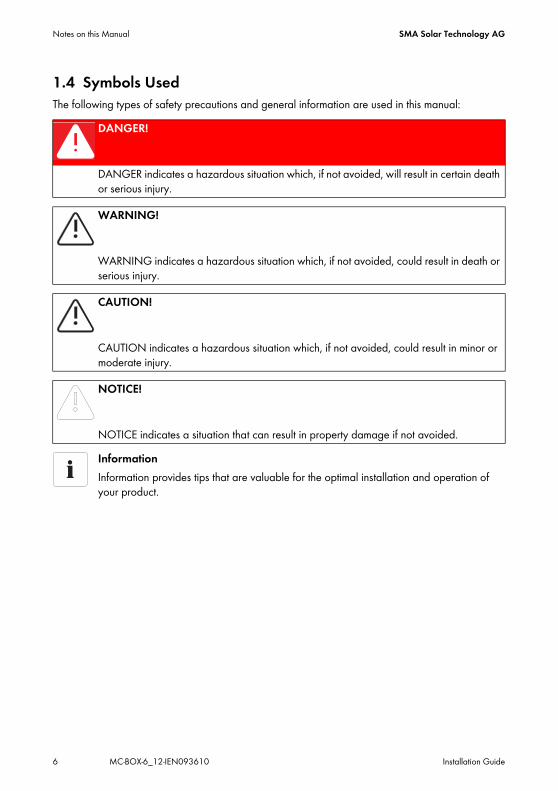
1.4 Symbols UsedThe following types of safety precautions and general information are used in this manual:
DANGER!
DANGER indicates a hazardous situation which, if not avoided, will result in certain death or serious injury.
WARNING!
WARNING indicates a hazardous situation which, if not avoided, could result in death or serious injury.
CAUTION!
CAUTION indicates a hazardous situation which, if not avoided, could result in minor or moderate injury.
NOTICE!
NOTICE indicates a situation that can result in property damage if not avoided.InformationInformation provides tips that are valuable for the optimal installation and operation of your product.

SMA Solar Technology AG Security
Installation Guide MC-BOX-6_12-IEN093610 7
2 Security2.1 Appropriate UsageThe Multicluster Box is a component of a Sunny Island Multicluster System. It is used to build island grids with several Sunny Island 5048 units. The Multicluster Box is an AC distribution to which you can connect the Sunny Island, the consumers, the generator or the grid and an additional generator as well as a photovoltaic system or wind turbines system.
Principle of a Sunny Island Multicluster System with a Multicluster Box 6.3
Connection requirementsThe Multicluster Box is suitable only for connection to TN grids.
Security SMA Solar Technology AG
8 MC-BOX-6_12-IEN093610 Installation Guide
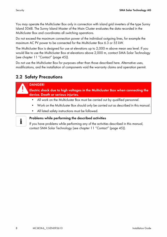
You may operate the Multicluster Box only in connection with island grid inverters of the type Sunny Island 5048. The Sunny Island Master of the Main Cluster evaluates the data recorded in the Multicluster Box and coordinates all switching operations.Do not exceed the maximum connection power of the individual outgoing lines, for example the maximum AC PV power to be connected for the Multicluster Box 6.3 or 55 kW.The Multicluster Box is designed for use at elevations up to 2,000 m above mean sea level. If you would like to use the Multicluster Box at elevations above 2,000 m, contact SMA Solar Technology (see chapter 11 ”Contact” (page 45)).Do not use the Multicluster Box for purposes other than those described here. Alternative uses, modifications, and the installation of components void the warranty claims and operation permit.
2.2 Safety PrecautionsDANGER!Electric shock due to high voltages in the Multicluster Box when connecting the device. Death or serious injuries.
• All work on the Multicluster Box must be carried out by qualified personnel.• Work on the Multicluster Box should only be carried out as described in this manual.• All listed safety instructions must be followed.
Problems while performing the described activitiesIf you have problems while performing any of the activities described in this manual, contact SMA Solar Technology (see chapter 11 ”Contact” (page 45)).

SMA Solar Technology AG Delivery
Installation Guide MC-BOX-6_12-IEN093610 9
3 Delivery3.1 Packing ListCheck the delivery for completeness. Check the packaging and the Multicluster Box for externally visible damage. Contact your supplier in case of damage to the packaging. Please contact your dealer if you find any damage to the Multicluster Box or if the delivery is incomplete.
3.1.1 Multicluster Box 6.3
Object Quantity DescriptionA 1 Multicluster BoxB 1 Switch cabinet keyC 1 Communication cable (5 m, black)D 3 Control and sensor cable (5 m each, red)E 1 Installation guideF 8 4 sealing rings and 4 washers (diameter: 6 mm)G 8 4 sealing rings and 4 washers (diameter: 8 mm)
Delivery SMA Solar Technology AG
10 MC-BOX-6_12-IEN093610 Installation Guide
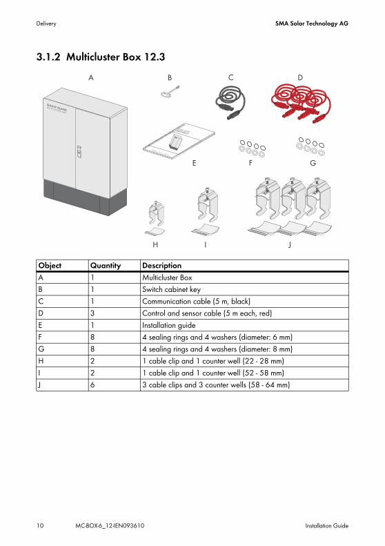
3.1.2 Multicluster Box 12.3
Object Quantity DescriptionA 1 Multicluster BoxB 1 Switch cabinet keyC 1 Communication cable (5 m, black)D 3 Control and sensor cable (5 m each, red)E 1 Installation guideF 8 4 sealing rings and 4 washers (diameter: 6 mm)G 8 4 sealing rings and 4 washers (diameter: 8 mm)H 2 1 cable clip and 1 counter well (22 - 28 mm)I 2 1 cable clip and 1 counter well (52 - 58 mm)J 6 3 cable clips and 3 counter wells (58 - 64 mm)
SMA Solar Technology AG Delivery
Installation Guide MC-BOX-6_12-IEN093610 11
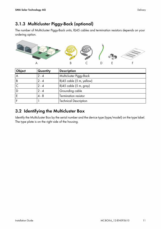
3.1.3 Multicluster Piggy-Back (optional)The number of Multicluster Piggy-Back units, RJ45 cables and termination resistors depends on your ordering option.
3.2 Identifying the Multicluster BoxIdentify the Multicluster Box by the serial number and the device type (type/model) on the type label. The type plate is on the right side of the housing.
Object Quantity DescriptionA 2 - 4 Multicluster Piggy-BackB 2 - 4 RJ45 cable (5 m, yellow)C 2 - 4 RJ45 cable (5 m, gray)D 2 - 4 Grounding cableE 4 - 8 Termination resistorF 1 Technical Description
Mounting and installation SMA Solar Technology AG
12 MC-BOX-6_12-IEN093610 Installation Guide
4 Mounting and installation4.1 Multicluster Box 6.3
4.1.1 Selecting the Mounting Location
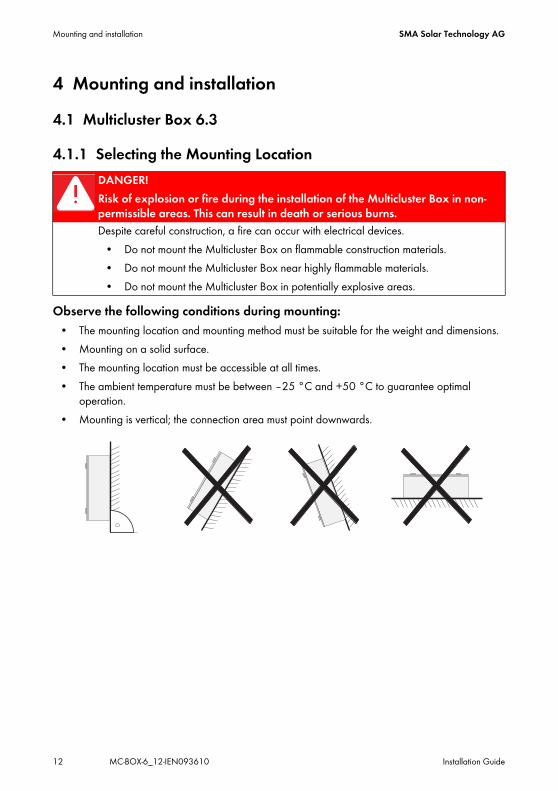
Observe the following conditions during mounting:• The mounting location and mounting method must be suitable for the weight and dimensions.• Mounting on a solid surface.• The mounting location must be accessible at all times.• The ambient temperature must be between –25 °C and +50 °C to guarantee optimal
operation.• Mounting is vertical; the connection area must point downwards.
DANGER!Risk of explosion or fire during the installation of the Multicluster Box in non-permissible areas. This can result in death or serious burns.Despite careful construction, a fire can occur with electrical devices.
• Do not mount the Multicluster Box on flammable construction materials.• Do not mount the Multicluster Box near highly flammable materials.• Do not mount the Multicluster Box in potentially explosive areas.

SMA Solar Technology AG Mounting and installation
Installation Guide MC-BOX-6_12-IEN093610 13
4.1.2 Mounting Multicluster Box 6.3 on the wall
1. Mark the position of the drill holes.
2. Drill the holes (recommended diameter: 6 mm) at the marked position.3. Open the Multicluster Box with the switch cabinet key supplied.
CAUTION!The Multicluster Box may fall down as a result of improper transportation. Physical injury and damage to the Multicluster Box.
• Take the Multicluster Box's weight (approx. 60 kg) into account.
Mounting and installation SMA Solar Technology AG
14 MC-BOX-6_12-IEN093610 Installation Guide
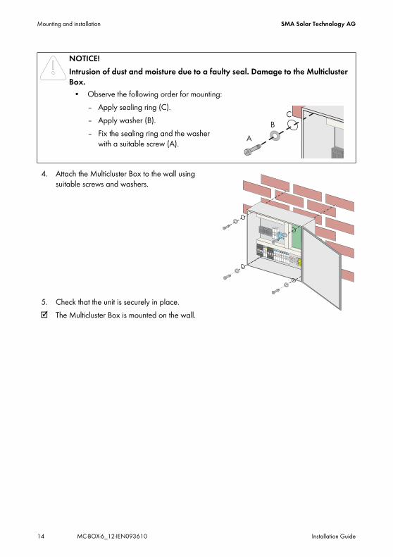
4. Attach the Multicluster Box to the wall using suitable screws and washers.
5. Check that the unit is securely in place.☑ The Multicluster Box is mounted on the wall.
NOTICE!Intrusion of dust and moisture due to a faulty seal. Damage to the Multicluster Box.
• Observe the following order for mounting:– Apply sealing ring (C).– Apply washer (B).– Fix the sealing ring and the washer
with a suitable screw (A).
SMA Solar Technology AG Mounting and installation
Installation Guide MC-BOX-6_12-IEN093610 15
4.2 Multicluster Box 12.3
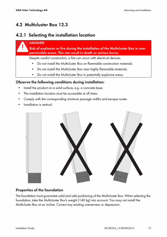
4.2.1 Selecting the installation location
Observe the following conditions during installation:• Install the product on a solid surface, e.g. a concrete base.• The installation location must be accessible at all times.• Comply with the corresponding minimum passage widths and escape routes• Installation is vertical.
Properties of the foundationThe foundation must guarantee solid and safe positioning of the Multicluster Box. When selecting the foundation, take the Multicluster Box's weight (140 kg) into account. You may not install the Multicluster Box at an incline. Correct any existing unevenness or depression.
DANGER!Risk of explosion or fire during the installation of the Multicluster Box in non-permissible areas. This can result in death or serious burns.Despite careful construction, a fire can occur with electrical devices.
• Do not install the Multicluster Box on flammable construction materials.• Do not install the Multicluster Box near highly flammable materials.• Do not install the Multicluster Box in potentially explosive areas.

Mounting and installation SMA Solar Technology AG
16 MC-BOX-6_12-IEN093610 Installation Guide
4.2.2 Transporting the Multicluster Box 12.3Transport possibilities
The Multicluster Box is delivered on a pallet. To lift the Multicluster Box from the pallet, you can use the following means of transportation:
• Forklift or pallet truck• Crane with appropriate fork
WARNING!The Multicluster Box may fall down as a result of improper transportation. Physical injury and damage to the Multicluster Box.
• The means of transportation must be suitable for the weight of the Multicluster Box.• Transport the Multicluster Box only upright.• Take the Multicluster Box's center of gravity into account. It is in the top third of the
Multicluster Box.
SMA Solar Technology AG Mounting and installation
Installation Guide MC-BOX-6_12-IEN093610 17
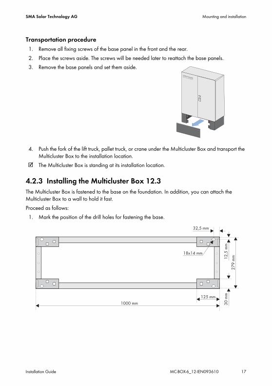
Transportation procedure1. Remove all fixing screws of the base panel in the front and the rear.2. Place the screws aside. The screws will be needed later to reattach the base panels.3. Remove the base panels and set them aside.
4. Push the fork of the lift truck, pallet truck, or crane under the Multicluster Box and transport the Multicluster Box to the installation location.
☑ The Multicluster Box is standing at its installation location.
4.2.3 Installing the Multicluster Box 12.3The Multicluster Box is fastened to the base on the foundation. In addition, you can attach the Multicluster Box to a wall to hold it fast.Proceed as follows:1. Mark the position of the drill holes for fastening the base.
Mounting and installation SMA Solar Technology AG
18 MC-BOX-6_12-IEN093610 Installation Guide
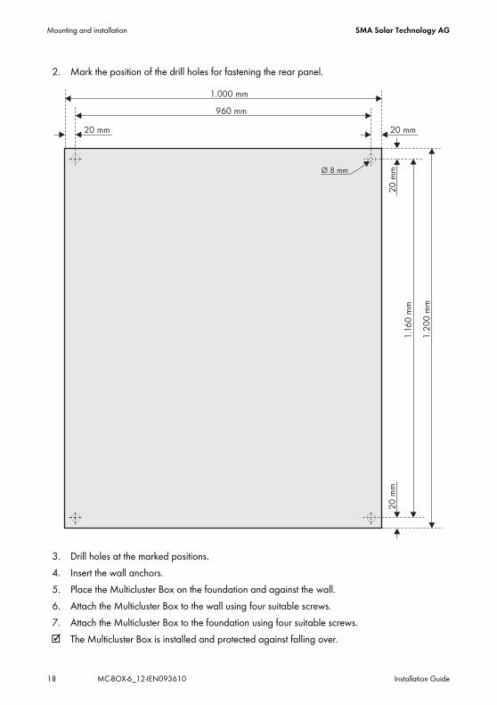
2. Mark the position of the drill holes for fastening the rear panel.
3. Drill holes at the marked positions.4. Insert the wall anchors.5. Place the Multicluster Box on the foundation and against the wall.6. Attach the Multicluster Box to the wall using four suitable screws.7. Attach the Multicluster Box to the foundation using four suitable screws.☑ The Multicluster Box is installed and protected against falling over.
SMA Solar Technology AG Electrical Connection
Installation Guide MC-BOX-6_12-IEN093610 19
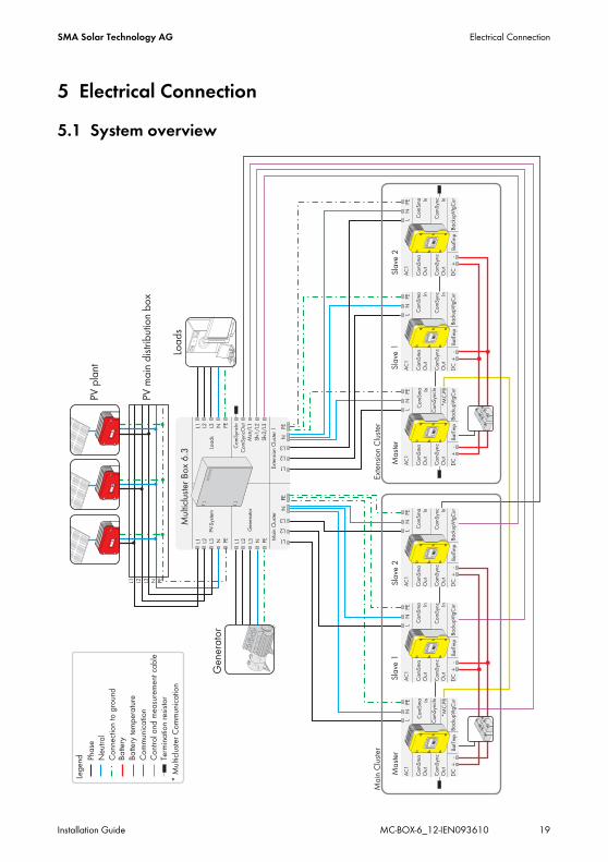
5 Electrical Connection5.1 System overview
Electrical Connection SMA Solar Technology AG
20 MC-BOX-6_12-IEN093610 Installation Guide
5.2 Overview of the Connection Area
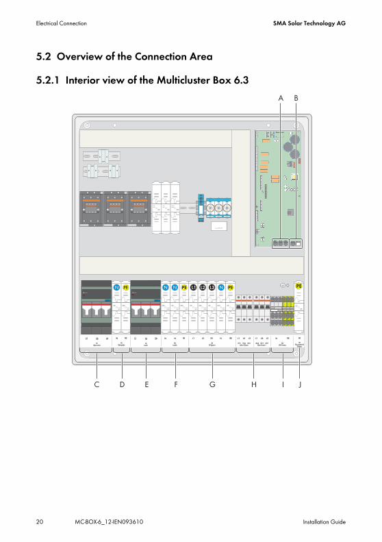
5.2.1 Interior view of the Multicluster Box 6.3
SMA Solar Technology AG Electrical Connection
Installation Guide MC-BOX-6_12-IEN093610 21
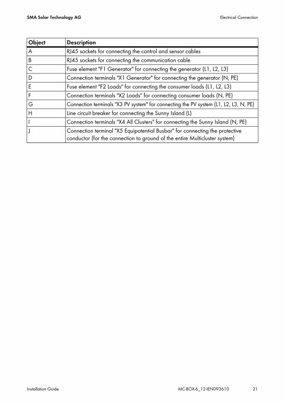
Object DescriptionA RJ45 sockets for connecting the control and sensor cablesB RJ45 sockets for connecting the communication cableC Fuse element "F1 Generator" for connecting the generator (L1, L2, L3)D Connection terminals "X1 Generator" for connecting the generator (N, PE)E Fuse element "F2 Loads" for connecting the consumer loads (L1, L2, L3)F Connection terminals "X2 Loads" for connecting consumer loads (N, PE)G Connection terminals "X3 PV system" for connecting the PV system (L1, L2, L3, N, PE)H Line circuit breaker for connecting the Sunny Island (L)I Connection terminals "X4 All Clusters" for connecting the Sunny Island (N, PE)J Connection terminal "X5 Equipotential Busbar" for connecting the protective
conductor (for the connection to ground of the entire Multicluster system)

Electrical Connection SMA Solar Technology AG
22 MC-BOX-6_12-IEN093610 Installation Guide
5.2.2 Interior view of the Multicluster Box 12.3
SMA Solar Technology AG Electrical Connection
Installation Guide MC-BOX-6_12-IEN093610 23
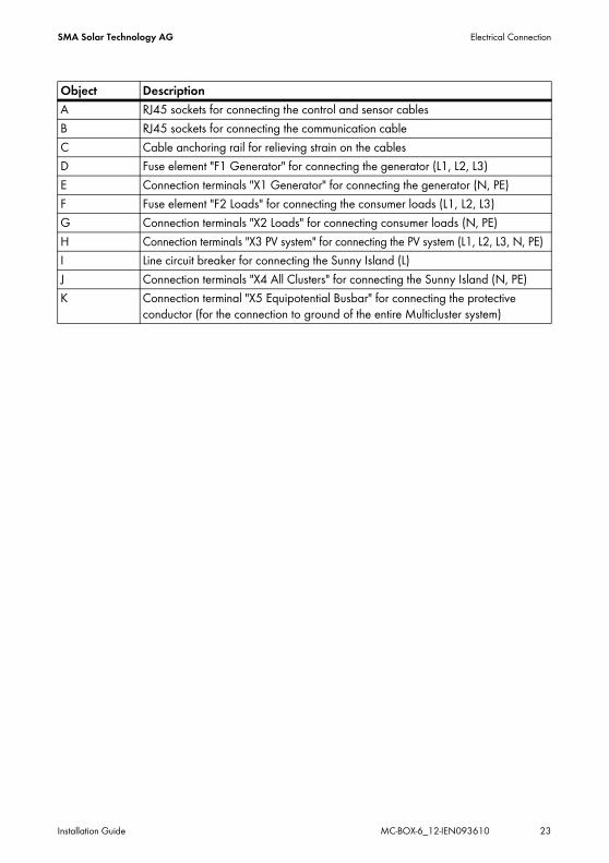
Object DescriptionA RJ45 sockets for connecting the control and sensor cablesB RJ45 sockets for connecting the communication cableC Cable anchoring rail for relieving strain on the cablesD Fuse element "F1 Generator" for connecting the generator (L1, L2, L3)E Connection terminals "X1 Generator" for connecting the generator (N, PE)F Fuse element "F2 Loads" for connecting the consumer loads (L1, L2, L3)G Connection terminals "X2 Loads" for connecting consumer loads (N, PE)H Connection terminals "X3 PV system" for connecting the PV system (L1, L2, L3, N, PE)I Line circuit breaker for connecting the Sunny Island (L)J Connection terminals "X4 All Clusters" for connecting the Sunny Island (N, PE)K Connection terminal "X5 Equipotential Busbar" for connecting the protective
conductor (for the connection to ground of the entire Multicluster system)
Electrical Connection SMA Solar Technology AG
24 MC-BOX-6_12-IEN093610 Installation Guide
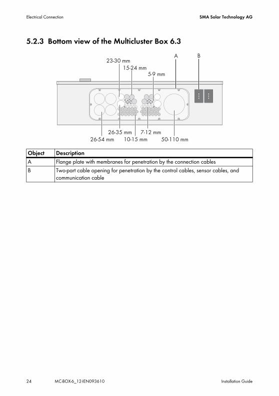
5.2.3 Bottom view of the Multicluster Box 6.3
Object DescriptionA Flange plate with membranes for penetration by the connection cablesB Two-part cable opening for penetration by the control cables, sensor cables, and
communication cable

SMA Solar Technology AG Electrical Connection
Installation Guide MC-BOX-6_12-IEN093610 25
5.2.4 Bottom view of the Multicluster Box 12.3 (without base)
Object DescriptionA Flange plate with membranes for penetration by the connection cablesB Two-part cable opening for penetration by the control cables, sensor cables, and
communication cable

Electrical Connection SMA Solar Technology AG
26 MC-BOX-6_12-IEN093610 Installation Guide
5.3 Preparing the cables
1. Select a suitable membrane for the insertion of the relevant cable.2. Pierce the selected membrane with a pointed object. The opening must not be too large.3. Guide the cable through the membrane into the interior of the Multicluster Box. The cable has
to be tightly enclosed by the membrane after it is inserted.4. Strip the insulation from the cable in accordance with the pipe cable shoe used.5. Provide the stripped cable with a suitable pipe cable shoe. This does not apply to the cables of
the Sunny Island.6. Connect the cable as described in the following chapters.
NOTICE!Penetration of humidity due to overextended rubber membrane in the connection area. Damage to the Multicluster Box.
• When inserting the cables, observe the maximum diameter of the rubber membranes. See chapter 5.2.3 ”Bottom view of the Multicluster Box 6.3” (page 24) and chapter 5.2.4 ”Bottom view of the Multicluster Box 12.3 (without base)” (page 25).
NOTICE!Too high mechanical load may cause the cables to become loose. Damage to the Multicluster Box.
• For the Multicluster Box 6.3, trap cables outside, for example using a cable anchoring rail.
• For the Multicluster Box 12.3, trap cables in the Multicluster Box on the cable anchoring rail provided for that purpose. Use the cable clips and counter wells provided for that purpose.
SMA Solar Technology AG Electrical Connection
Installation Guide MC-BOX-6_12-IEN093610 27
5.4 Connecting the cables
5.4.1 Connecting the generatorYou can connect a three-phase generator, such as a diesel generator or another grid-forming current generator, to the Multicluster Box. You also have the possibility of connecting the public grid.The phases L1, L2, and L3 are led through fuse elements in the Multicluster Box. The fuse plugs are designed for a nominal current of 80 A (Multicluster Box 6.3) or 160 A (Multicluster Box 12.3). Determine the required fuse size according to layout type of the cable and installation conditions, and install the appropriate fuse plugs. The maximum usable fuse plugs in each case are factory-installed in the fuse element.Cable DesignIf the generator has no output fuse, you have to lay the cable to the Multicluster Box in a ground-fault proof and short-circuit proof manner. Alternatively, it is advisable – especially if the cable routes are long – to use an additional fuse box near the generator.
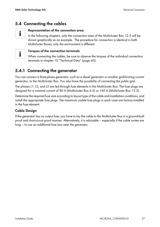
Representation of the connection areaIn the following chapters, only the connection area of the Multicluster Box 12.3 will be shown graphically as an example. The procedure for connection is identical in both Multicluster Boxes; only the environment is different.Torques of the connection terminalsWhen connecting the cables, be sure to observe the torques of the individual connection terminals in chapter 10 ”Technical Data” (page 43).
Electrical Connection SMA Solar Technology AG
28 MC-BOX-6_12-IEN093610 Installation Guide
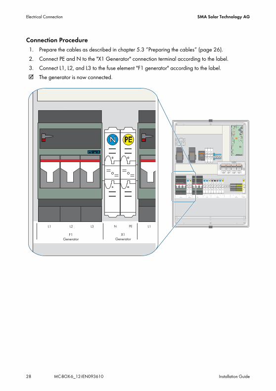
Connection Procedure1. Prepare the cables as described in chapter 5.3 ”Preparing the cables” (page 26).2. Connect PE and N to the "X1 Generator" connection terminal according to the label.3. Connect L1, L2, and L3 to the fuse element "F1 generator" according to the label.☑ The generator is now connected.
SMA Solar Technology AG Electrical Connection
Installation Guide MC-BOX-6_12-IEN093610 29
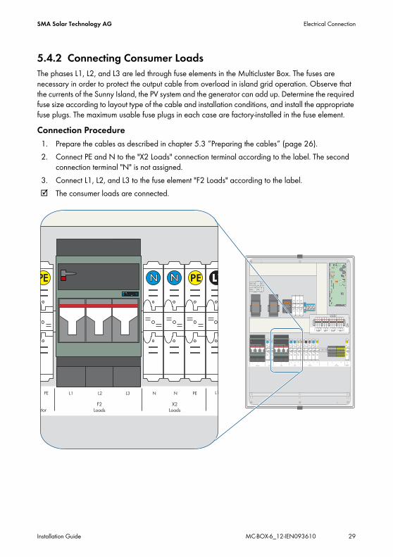
5.4.2 Connecting Consumer LoadsThe phases L1, L2, and L3 are led through fuse elements in the Multicluster Box. The fuses are necessary in order to protect the output cable from overload in island grid operation. Observe that the currents of the Sunny Island, the PV system and the generator can add up. Determine the required fuse size according to layout type of the cable and installation conditions, and install the appropriate fuse plugs. The maximum usable fuse plugs in each case are factory-installed in the fuse element.Connection Procedure1. Prepare the cables as described in chapter 5.3 ”Preparing the cables” (page 26).2. Connect PE and N to the "X2 Loads" connection terminal according to the label. The second
connection terminal "N" is not assigned.3. Connect L1, L2, and L3 to the fuse element "F2 Loads" according to the label.☑ The consumer loads are connected.

Electrical Connection SMA Solar Technology AG
30 MC-BOX-6_12-IEN093610 Installation Guide
5.4.3 Connecting the PV System
Cable DesignIn a short circuit, the short-circuit currents driven by the generator flow over the unprotected cable between the Multicluster Box and the PV main distributor. If the fuse of the generator is larger than the fuse in the PV main distributor, you have to accommodate the cable to the generator's fuse.With regard to short-circuit protection, the PV inverters and the Sunny Island do not need to be taken into account as due to their design, they cannot endanger the cables if a short circuit occurs. Overload protection is always guaranteed if the cables which you route to the PV system are designed for at least the feed-in power of the PV system.
Cable protectionThe Multicluster Box does not replace the distributor box or fuse box of the PV system (PV main distributor). For purposes of fuse protection and isolation, install a line circuit breaker, and if necessary a residual current breaker, between the Multicluster Box and the PV system. Be sure to observe all standards and guidelines applicable to the installation site.Connecting other energy sourcesInstead of the PV system, you can also connect other energy sources (e.g. small wind turbine systems) to the Multicluster Box.
SMA Solar Technology AG Electrical Connection
Installation Guide MC-BOX-6_12-IEN093610 31
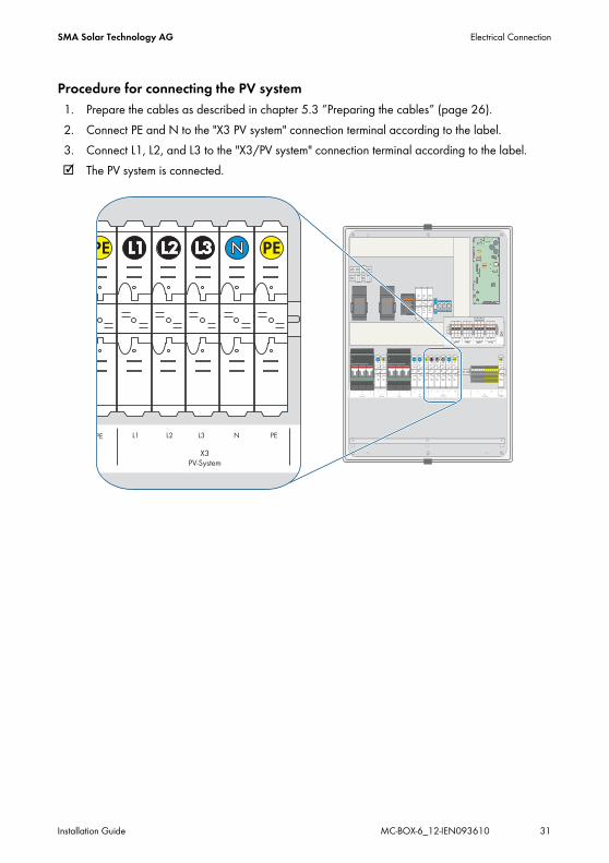
Procedure for connecting the PV system1. Prepare the cables as described in chapter 5.3 ”Preparing the cables” (page 26).2. Connect PE and N to the "X3 PV system" connection terminal according to the label.3. Connect L1, L2, and L3 to the "X3/PV system" connection terminal according to the label.☑ The PV system is connected.
Electrical Connection SMA Solar Technology AG
32 MC-BOX-6_12-IEN093610 Installation Guide
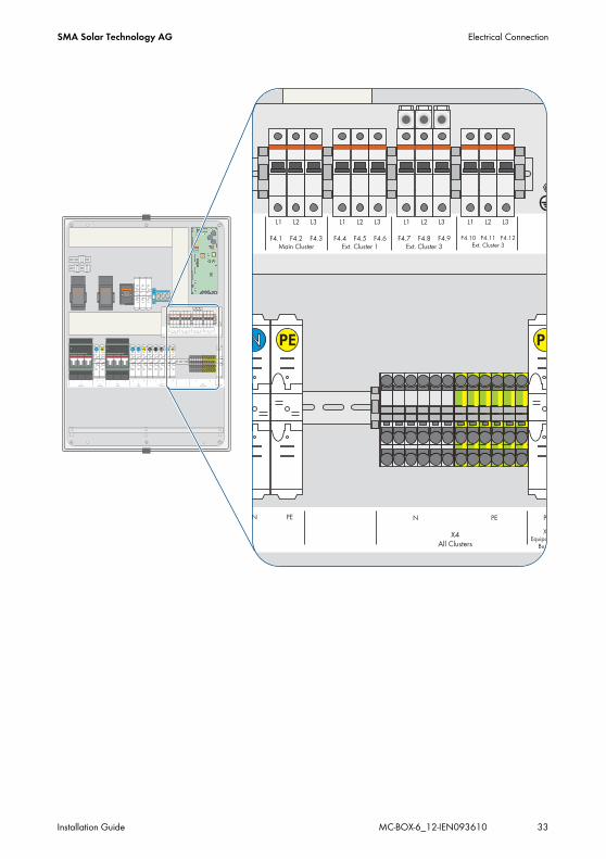
5.4.4 Connecting Sunny Island
Connection Procedure1. Prepare the cables as described in chapter 5.3 ”Preparing the cables” (page 26).2. Connect PE and N of all Sunny Island units to the "X4 All Clusters" connection terminal
according to the label.3. Connect Main Cluster:
– Connect phase L of the Sunny Island master to L1 of the line circuit breaker "F4.1 Main Cluster".
– Connect phase L of the Sunny Island slave 1 to L2 of the line circuit breaker "F4.2 Main Cluster".
– Connect phase L of the Sunny Island slave 2 to L3 of the line circuit breaker "F4.3 Main Cluster".
4. Connect Extension Cluster 1 to the line circuit breakers "F4.4 – F4.6 Ext. Cluster 1". To connect the Extension Cluster 1, proceed as described under point 3.
5. Connect Extension Cluster 2 to the line circuit breakers "F4.7 – F4.9 Ext. Cluster 2". To connect the Extension Cluster 2, proceed as described under point 3.
6. Connect Extension Cluster 3 to the line circuit breakers "F4.10 – F4.12 Ext. Cluster 3". To connect the Extension Cluster 3, proceed as described under point 3.
☑ The Sunny Island units are connected.
Securing the Sunny IslandEach Sunny Island is secured with a C32 A line circuit breaker inside the Multicluster Box.
SMA Solar Technology AG Electrical Connection
Installation Guide MC-BOX-6_12-IEN093610 33

Electrical Connection SMA Solar Technology AG
34 MC-BOX-6_12-IEN093610 Installation Guide
5.4.5 Connection to GroundGround the Multicluster system outside the Multicluster Box on the equipotential busbar:1. Prepare the cables as described in chapter 5.3 ”Preparing the cables” (page 26).2. Connect PE to the terminal for ground connection cable "X5 Equipotential Busbar" and connect
it to the equipotential busbar.☑ The Multicluster system is grounded.
SMA Solar Technology AG Electrical Connection
Installation Guide MC-BOX-6_12-IEN093610 35
5.5 CommunicationThe Multicluster Box transfers voltage measurement signals and current measurement signals to the Sunny Island units. These signals are transferred via the control cables and sensor cables (red). The Multicluster Box is controlled by the Sunny Island master in the Main Cluster via a CAN bus.Before you can connect the control, sensor and communication cables in the Multicluster Box, you have to guide the cables into the interior of the Multicluster Box through the two-part cable openings. To do this, proceed as in chapter 5.5.1 ”Guiding the cables into the Multicluster Box” (page 35). Then connect the cables as described in chapter 5.5.2 ”Connecting the control and sensor cables” (page 37) and chapter 5.5.3 ”Connecting the communication cable” (page 38).
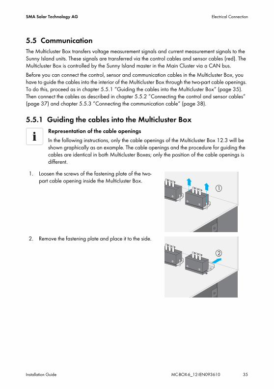
5.5.1 Guiding the cables into the Multicluster Box
1. Loosen the screws of the fastening plate of the two-part cable opening inside the Multicluster Box.
2. Remove the fastening plate and place it to the side.
Representation of the cable openingsIn the following instructions, only the cable openings of the Multicluster Box 12.3 will be shown graphically as an example. The cable openings and the procedure for guiding the cables are identical in both Multicluster Boxes; only the position of the cable openings is different.

Electrical Connection SMA Solar Technology AG
36 MC-BOX-6_12-IEN093610 Installation Guide
3. Remove cable opening from the housing.
4. Loosen screws of the two-part cable opening.
5. Remove the half without the T-shaped fastening pieces.
6. Lay a communication cable as well as a control and sensor cable with sufficient length from the opening to the desired connection through the part of the cable opening with the T-shaped fastening pieces. Fix them in place with cable ties.
7. Bolt the halves back together. Fasten the screws finger-tight.The cables and the placeholder (plastic rod) have to be fitted tightly between both sides of the two-part cable opening. Otherwise, a proper seal of the enclosure cannot be guaranteed.
8. Insert cable opening including cable into the housing from the outside.
SMA Solar Technology AG Electrical Connection
Installation Guide MC-BOX-6_12-IEN093610 37
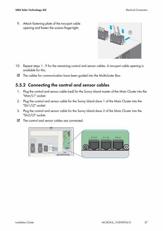
9. Attach fastening plate of the two-part cable opening and fasten the screws finger-tight.
10. Repeat steps 1 - 9 for the remaining control and sensor cables. A two-part cable opening is available for this.
☑ The cables for communication have been guided into the Multicluster Box.
5.5.2 Connecting the control and sensor cables1. Plug the control and sensor cable (red) for the Sunny Island master of the Main Cluster into the
"Mstr/L1" socket.2. Plug the control and sensor cable for the Sunny Island slave 1 of the Main Cluster into the
"Slv1/L2" socket.3. Plug the control and sensor cable for the Sunny Island slave 2 of the Main Cluster into the
"Slv2/L3" socket.☑ The control and sensor cables are connected.

Electrical Connection SMA Solar Technology AG
38 MC-BOX-6_12-IEN093610 Installation Guide
5.5.3 Connecting the communication cable1. Plug the communication cable (black) for communication between Sunny Island and the
Multicluster Box into the "ComSyncIn" socket. Leave the termination resistor plugged into the "ComSyncOut" socket.
2. Connect the end of the communication cable into the "ComSyncIn" socket on a Sunny Island in the Main Cluster. Since all Sunny Island units (master and slaves) of the Main Cluster are connected via a communication bus, the Multicluster Box can be connected to a slave or to the master of the Main Cluster.
☑ The communication cable is connected.

SMA Solar Technology AG Commissioning the Multicluster Box
Installation Guide MC-BOX-6_12-IEN093610 39
6 Commissioning the Multicluster BoxCheck the following requirements before commissioning the Sunny Island Multicluster System:
• The Multicluster Box is installed properly.• All cables are correctly and completely connected.• All cables are tightly enclosed by the membrane on the bottom of the Multicluster Box.• All cables are trapped on a cable anchoring rail inside or outside the Multicluster Box.• The base panels on the base of the Multicluster Box 12.3 are attached.
Once all requirements are met, commission the Sunny Island Multicluster System as described in the technical description of the Sunny Island 5048.
Opening and Closing SMA Solar Technology AG
40 MC-BOX-6_12-IEN093610 Installation Guide
7 Opening and Closing7.1 Opening the Multicluster Box
1. Shut down the Sunny Island Multicluster system as described in the Sunny Island 5048 manual.2. Switch off the external line circuit breaker and prevent it from being reactivated.3. Detach the Multicluster Box from all voltage sources.4. Open the enclosure with the switch cabinet key.5. Measure voltage to ensure that none is present in the system.☑ The Multicluster Box is open.
7.2 Closing the Multicluster Box1. Close the enclosure of the Multicluster Box with the switch cabinet key.2. Commission the Multicluster Box as described in chapter 6 ”Commissioning the Multicluster
Box” (page 39).☑ The Multicluster Box is closed and in operation.
NOTICE!Touching the components inside the Multicluster Box can result in electric discharge. Irreparable Damage.
• Ground yourself before touching a component.
SMA Solar Technology AG Maintenance
Installation Guide MC-BOX-6_12-IEN093610 41
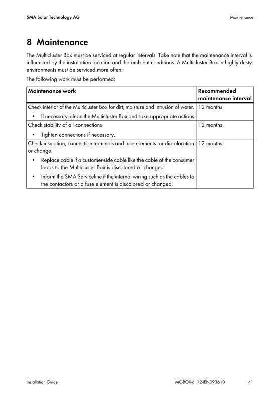
8 MaintenanceThe Multicluster Box must be serviced at regular intervals. Take note that the maintenance interval is influenced by the installation location and the ambient conditions. A Multicluster Box in highly dusty environments must be serviced more often. The following work must be performed:Maintenance work Recommended
maintenance intervalCheck interior of the Multicluster Box for dirt, moisture and intrusion of water.
• If necessary, clean the Multicluster Box and take appropriate actions.12 months
Check stability of all connections • Tighten connections if necessary.
12 months
Check insulation, connection terminals and fuse elements for discoloration or change.
• Replace cable if a customer-side cable like the cable of the consumer loads to the Multicluster Box is discolored or changed.
• Inform the SMA Serviceline if the internal wiring such as the cables to the contactors or a fuse element is discolored or changed.
12 months
Decommissioning SMA Solar Technology AG
42 MC-BOX-6_12-IEN093610 Installation Guide
9 Decommissioning9.1 Disassembly
9.1.1 Disassembling the Multicluster Box 6.3
1. Open the Multicluster Box as described in chapter 7.1 ”Opening the Multicluster Box” (page 40).
2. Remove all cables from the Multicluster Box.3. Unscrew the fixing screws of the Multicluster Box.4. Remove the Multicluster Box.5. Close the the Multicluster Box with the switch cabinet key.☑ The Multicluster Box is disassembled.
9.1.2 Disassembling the Multicluster Box 12.31. Open the Multicluster Box as described in chapter 7.1 ”Opening the Multicluster Box”
(page 40).2. Remove all fixing screws of the base panel in the front and the rear.3. Place the screws aside. They will be needed later to reattach the base panels.4. Remove all cables from the Multicluster Box.5. Unscrew and remove the fixing screws of the Multicluster Box.6. Close the enclosure of the Multicluster Box with the switch cabinet key.7. Transport the Multicluster Box with a forklift, pallet truck, or crane.8. Mount the base panels back on the Multicluster Box.☑ The Multicluster Box is disassembled.
9.2 Storing the ProductStore the Multicluster Box in a dry place where the ambient temperature is always between –25 °C and +50 °C.
9.3 DisposalDispose of the Multicluster Box at the end of its service life in accordance with the disposal regulations for electronic waste applicable at the installation site at that time.
CAUTION!Risk of injury from Multicluster Box falling during transport. Physical injury (fractures or crushing) and damage to the Multicluster Box.
• Take the Multicluster Box's weight (60 kg) into account.
SMA Solar Technology AG Technical Data
Installation Guide MC-BOX-6_12-IEN093610 43
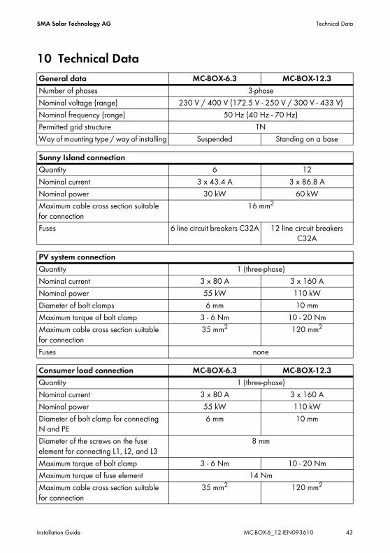
10 Technical DataGeneral data MC-BOX-6.3 MC-BOX-12.3Number of phases 3-phaseNominal voltage (range) 230 V / 400 V (172.5 V - 250 V / 300 V - 433 V)Nominal frequency (range) 50 Hz (40 Hz - 70 Hz)Permitted grid structure TNWay of mounting type / way of installing Suspended Standing on a base
Sunny Island connectionQuantity 6 12Nominal current 3 x 43.4 A 3 x 86.8 ANominal power 30 kW 60 kWMaximum cable cross section suitable for connection
16 mm2
Fuses 6 line circuit breakers C32A 12 line circuit breakers C32A
PV system connectionQuantity 1 (three-phase)Nominal current 3 x 80 A 3 x 160 ANominal power 55 kW 110 kWDiameter of bolt clamps 6 mm 10 mmMaximum torque of bolt clamp 3 - 6 Nm 10 - 20 NmMaximum cable cross section suitable for connection
35 mm2 120 mm2
Fuses none
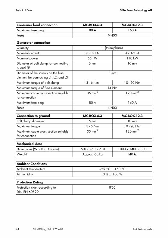
Consumer load connection MC-BOX-6.3 MC-BOX-12.3Quantity 1 (three-phase)Nominal current 3 x 80 A 3 x 160 ANominal power 55 kW 110 kWDiameter of bolt clamp for connecting N and PE
6 mm 10 mm
Diameter of the screws on the fuse element for connecting L1, L2, and L3
8 mm
Maximum torque of bolt clamp 3 - 6 Nm 10 - 20 NmMaximum torque of fuse element 14 NmMaximum cable cross section suitable for connection
35 mm2 120 mm2
Technical Data SMA Solar Technology AG
44 MC-BOX-6_12-IEN093610 Installation Guide
Maximum fuse plug 80 A 160 AFuses NH00Generator connectionQuantity 1 (three-phase)Nominal current 3 x 80 A 3 x 160 ANominal power 55 kW 110 kWDiameter of bolt clamp for connecting N and PE
6 mm 10 mm
Diameter of the screws on the fuse element for connecting L1, L2, and L3
8 mm
Maximum torque of bolt clamp 3 - 6 Nm 10 - 20 NmMaximum torque of fuse element 14 NmMaximum cable cross section suitable for connection
35 mm2 120 mm2
Maximum fuse plug 80 A 160 AFuses NH00
Connection to ground MC-BOX-6.3 MC-BOX-12.3Bolt clamp diameter 6 mm 10 mmMaximum torque 3 - 6 Nm 10 - 20 NmMaximum cable cross section suitable for connection
35 mm2 120 mm2
Mechanical dataDimensions (W x H x D in mm) 760 x 760 x 210 1000 x 1400 x 300Weight Approx. 60 kg 140 kg
Ambient ConditionsAmbient temperature –25 °C ... +50 °C Air humidity 0 % ... 100 %
Protection RatingProtection class according to DIN EN 60529
IP65
Consumer load connection MC-BOX-6.3 MC-BOX-12.3
SMA Solar Technology AG Contact
Installation Guide MC-BOX-6_12-IEN093610 45
11 ContactIf you have technical problems concerning our products, contact the SMA Serviceline. We need the following information in order to provide you with the necessary assistance:
• Type of Multicluster Box• Serial number of the Multicluster Box• Type and number of the connected Sunny Island units• Type and number of connected PV inverters• Description of connected consumer loads• If a generator is connected:
– Type– Power– Maximum current
SMA Solar Technology AGSonnenallee 134266 Niestetal, GermanyTel. +49 561 9522 399 Fax +49 561 9522 4697 [email protected] www.SMA.de

Contact SMA Solar Technology AG
46 MC-BOX-6_12-IEN093610 Installation Guide
SMA Solar Technology AG Legal Restrictions
Installation Guide MC-BOX-6_12-IEN093610 47
The information contained in this document is the property of SMA Solar Technology AG. Publishing its content, either partially or in full, requires the written permission of SMA Solar Technology AG. Any internal company copying of the document for the purposes of evaluating the product or its correct implementation is allowed and does not require permission.
Exclusion of liabilityThe general terms and conditions of delivery of SMA Solar Technology AG shall apply.The content of these documents is continually checked and amended, where necessary. However, discrepancies cannot be excluded. No guarantee is made for the completeness of these documents. The latest version is available online at www.SMA.de or from the usual sales channels.Guarantee or liability claims for damages of any kind are excluded if they are caused by one or more of the following: • Damages during transportation• Improper or inappropriate use of the product• Operating the product in an unintended environment• Operating the product whilst ignoring relevant, statutory safety regulations in the deployment location• Ignoring safety warnings and instructions contained in all documents relevant to the product• Operating the product under incorrect safety or protection conditions• Altering the product or supplied software without authority• The product malfunctions due to operating attached or neighboring devices beyond statutory limit values• In case of unforeseen calamity or force majeureThe use of supplied software produced by SMA Solar Technology AG is subject to the following conditions:• SMA Solar Technology AG rejects any liability for direct or indirect damages arising from the use of software developed by
SMA Solar Technology AG. This also applies to the provision or non-provision of support activities.• Supplied software not developed by SMA Solar Technology AG is subject to the respective licensing and liability agreements
of the manufacturer.
SMA Factory WarrantyThe current guarantee conditions come enclosed with your device. These are also available online at www.SMA.de and can be downloaded or are available on paper from the usual sales channels if required.
TrademarksAll trademarks are recognized even if these are not marked separately. Missing designations do not mean that a product or brand is not a registered trademark.The Bluetooth® word mark and logos are registered trademarks owned by Bluetooth SIG, Inc. and any use of such marks by SMA Solar Technology is under license.SMA Solar Technology AGSonnenallee 134266 NiestetalGermanyTel. +49 561 9522-0Fax +49 561 9522-100www.SMA.deE-Mail: [email protected]© 2004 to 2009 SMA Solar Technology AG. All rights reserved

SMA Solar Technology AG
www.SMA.de