super lightweight tank · - super lightweight tank - a risk management case study in mass reduction...
TRANSCRIPT
- Super Lightweight Tank -
A Risk Management Case Study in Mass Reduction
Abstract: The following case study exercise provides lessons learned from the development and operations of the Space Shuttle Program (SSP). It is intended to highlight key transferable aspects of risk management, which may vary slightly from a particular case study to the next. Transferable principles include the identification of risks, evaluation of risks, mitigation of risks, risk trades, and risk management processes. The proper application of risk management principles examined here can help manage life-cycle costs, development schedules, and risk, resulting in safer and more reliable systems for Constellation and other future programs. This case study format is intended to simulate the experience of facing the same difficult challenges and making the same critical decisions as the original managers, engineers, and scientists in the SSP. The case study will provide the background information and complementary data necessary to analyze the situation and answer the questions posed at key decision points in the case study. Solutions from the SLWT Team on what they actually did to solve the key decision questions are provided in the Appendices, followed by an Epilogue in which the actual decisions and outcomes are presented. The key lessons learned from conducting this exercise address how risks were identified, how they were evaluated, and how final choices were made.

1 | P a g e
Mass reduction plays a critical role in performance products across many industries, ranging from stock car racing to jetliners and military armor to recreational sports equipment. It is certain to continue to be a prominent topic for the Constellation Program and future space flight operations, as well as many industries across the globe. For the Space Shuttle, mass reduction (or weight) was a continual theme throughout the design, development, and operations of nearly every element. Mass is critical because it is directly coupled with lift capability. Lift capability determines when the Shuttle can launch, where it can go, and what it can carry. Less mass in the system means increased performance through increased lift or increased Shuttle payload.
Introduction to: “Super Light Weight Tank: A Risk Management Case Study in Mass Reduction”
The “Super Light Weight Tank”: Risk Management Case Study in Mass Reduction focuses on the development of the Super Light Weight Tank (SLWT), the third version of the External Tank (ET) component of the Space Shuttle. By walking the reader through the events as they happened, the reader will experience how an aggressive mass reduction plan levied on the ET component was achieved. We will examine the process of identifying and evaluating the risks and challenges that threatened the success of the project. Then, we will compare the user’s answers to those of the actual SLWT project team. Finally, the case study Epilogue describes the actual project team’s responses to the challenges that they faced, including a series of important lessons learned that the SLWT team captured to communicate to future programs and projects.
September 1993
The Commitment to the International Space Station
In June of 1993, amidst serious consideration by the U.S. Congress to cancel the almost decade-long space station program, an article from The New York Times
(see below) reported that the expert panel advising the White House on redesigning the astronaut outpost had urged that the station be launched into a “world orbit” so that that Russians, Japanese, and Chinese rockets could reach it. After a House vote previously in that same month, the station had survived cancellation by only one vote. Then on September 2, 1993, in a significant turn of events, representatives from the United States and Russia officially signed the Joint Declaration on Cooperation in Space, paving the way for a massive, unprecedented partnership to complete and operate the space station.
When President Bill Clinton took office in January 1993, he was advised by his budget director to cancel the space station program. The program, then named Freedom, had been established in 1984 under the Reagan Administration and was well behind schedule and over budget. The design alone had cost over $11 billion, and not even a single piece of hardware had yet been launched into space. It had been redesigned multiple times, progressively sacrificing capabilities to control ballooning costs. But where others saw failure, NASA Administrator Dan Goldin had convinced President Clinton and Vice President Al Gore to see opportunity. The Clinton Administration had been actively searching for a way to rejuvenate political relations with Russia when Goldin suggested forging a massive space partnership between the two nations by bringing them aboard the space station program. A Russian alliance would not only save billions of dollars and accelerate the time to completion, it would preserve the ability for the United States to access the station during a potential grounding of the Shuttle (as occurred after the Challenger disaster in 1986). President Clinton accepted this proposal and directed NASA to increase the orbital inclination of the space station, now renamed the International Space Station (ISS), to support Russian participation in the largest space collaboration in history.
2 | P a g e
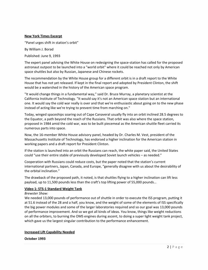
“Panel urges shift in station’s orbit”
New York Times Excerpt
By William J. Borad
Published: June 9, 1993
The expert panel advising the White House on redesigning the space-station has called for the proposed astronaut outpost to be launched into a "world orbit" where it could be reached not only by American space shuttles but also by Russian, Japanese and Chinese rockets.
The recommendation by the White House group for a different orbit is in a draft report to the White House that has not yet released. If kept in the final report and adopted by President Clinton, the shift would be a watershed in the history of the American space program.
"It would change things in a fundamental way," said Dr. Bruce Murray, a planetary scientist at the California Institute of Technology. "It would say it's not an American space station but an international one. It would say the cold war really is over and that we're enthusiastic about going on to the new phase instead of acting like we're trying to prevent time from marching on."
Today, winged spaceships soaring out of Cape Canaveral usually fly into an orbit inclined 28.5 degrees to the Equator, a path beyond the reach of the Russians. That orbit was also where the space station, proposed in 1984 amid the cold war, was to be built piecemeal as the American shuttle fleet carried its numerous parts into space.
Now, the 16-member White House advisory panel, headed by Dr. Charles M. Vest, president of the Massachusetts Institute of Technology, has endorsed a higher inclination for the American station in working papers and a draft report for President Clinton.
If the station is launched into an orbit the Russians can reach, the white paper said, the United States could “use their entire stable of previously developed Soviet launch vehicles – as needed.”
Cooperation with Russians could reduce costs, but the paper noted that the station’s current international partners, Japan, Canada, and Europe, “generally disagree with us about the desirability of the orbital inclination.”
The drawback of the proposed path, it noted, is that shuttles flying to a higher inclination can lift less payload, up to 11,500 pounds less than the craft’s top lifting power of 55,000 pounds…
Brewster Shaw: Video 1: STS-1 Standard Weight Tank
We needed 13,000 pounds of performance out of shuttle in order to execute the ISS program, putting it at 51.6 instead of the 28 and a half, you know, and the weight of some of the elements of ISS specifically the big power modules and some of the larger laboratories required and so our goal was 13,000 pounds of performance improvement. And so we got all kinds of ideas. You know, things like weight reductions on all the orbiters, to burning the OMS engines during ascent, to doing a super light weight tank project, which gave us the largest singular contribution to the performance enhancement.
October 1993
Increased Lift Capability Needed

3 | P a g e
The increased lift capability needed for the Space Shuttle to reach the higher orbital inclination of the ISS is now estimated at 13,500 pounds according to the most current calculations from the Space Shuttle Program (SSP) Office, which is 2,000 pounds more than what was predicted back in June. The SSP has no choice but to achieve this lift capability. President Clinton has mandated it, and NASA Administrator Goldin has promised it. Beginning in December 1997, the primary objective of the SSP will be to support the assembly of the ISS. Of the 34 planned primary SSP payloads, 27 will be ISS-related. In order to construct the ISS by the planned 2002 deadline, the 13,500 pounds of lift cannot come from reduced payloads. The Space Shuttle itself must find places to cut mass.
For the Project Manager for the External Tank (ET), this job will not be easy. The SSP has a history of mass reductions that were made to maximize the current payload capacity. Almost every component considered expendable has already been eliminated. The ET Project is already using a second generation ET that was specifically designed to be 12,000 pounds lighter than the original tank (a mass reduction of over 15%). One month from now, all of the Project Managers must propose strategies for mass reduction to the Space Shuttle Program Manager. The other Project Managers of the key Space Shuttle components have started on their plans. The Orbiter Project Manager says that his team is scraping to find solutions. They cannot simply construct a newer, lighter Orbiter. They must work with their current vehicles. The Orbiter team is actually considering removing contingency consumables, including water, oxygen, and food to save mass. The Solid Rocket Booster Project Manager is considering a redesign of the Solid Rocket Motor (SRM) in order to save mass. But he is uncertain if NASA would be willing to invest in the design and construction of a new Advanced Solid Rocket Motor (ASRM), since the current SRM’s are reusable. The ET Project team has also identified a number of optimizations that would reduce mass by a couple hundred pounds. But the ET needs a mass reduction in the thousands of pounds in order to make its “fair” contribution to the mass savings. There is an advantage available to the ET: they are not reusable. A new ET must be produced for every flight anyway, so a significant redesign is a realistic possibility.
The goal is set, and the deadline is fixed. The only problem is how to actually accomplish the mass reduction.
The Space Shuttle, or Space Transportation System (STS), is comprised of three major components: the Orbiter with three Space Shuttle Main Engines (SSMEs), a pair of Solid Rocket Boosters (SRBs), and the External Tank (ET). The reusable Orbiter carries the crew and the payload. It has three SSMEs for propulsion, but over 80% of the thrust during liftoff is provided by the twin SRBs, which contain solid propellant and are also recoverable so as to reuse the expensive SRMs. The ET serves as the structural backbone of
Mass Breakdown: The Space Shuttle Assembly
Figure 1: Space Shuttle assembly with approximate weights during the Light Weight Tank (LWT) era, 1983-1998.

4 | P a g e
the Space Shuttle assembly, connecting to both the Orbiter and the SRBs (shown in Figure 1). It supplies liquid oxygen and liquid hydrogen fuel to the Orbiter’s SSMEs, is physically the largest component of the Space Shuttle assembly, and is the only component that is not reused.
During the launch sequence, at about T minus 6 seconds, the SSMEs are activated. They must reach 90% thrust by T minus 3 seconds to proceed with launch. At T minus 0 seconds, the SRBs are ignited. The Space Shuttle assembly, weighing about 4.5 million pounds at launch, is accelerated to 100 mph in eight seconds. The SRBs burn for about two minutes, consuming a combined 2.2 million pounds of propellant over this time. At about 150,000 ft, the empty SRBs are jettisoned from the ET. Each SRB deploys its own parachute and lands safely in the ocean, where they are recovered. The Orbiter and ET continue to ascend, now powered only by the SSMEs which are fed liquid fuel at a rate of 1,035 gallons per second. About eight and a half minutes after launch, the Orbiter is close to its required 18,000 mph needed to reach orbit and the ET has emptied almost 29 swimming pools worth of liquid fuel (about 1.6 million pounds). At that point, the three SSMEs are shut down. 18 seconds later, the ET is released from the Orbiter. Gaseous oxygen is vented from a valve in the nose of the ET, which induces a self-destructive tumble rate designed to break up the ET over the ocean at just below 250,000 ft (a “safe” debris altitude mandated by international treaties) where most pieces burn up during re-entry.
Overall, more than 80% of the weight of the Space Shuttle assembly at launch is just the fuel needed to lift the Orbiter into space. Mass savings on any component can be directly applied to launch performance or more payload for the Orbiter to carry into space. Therefore, weight, or mass reduction, has always been a top priority since the inception of the space program. Both the Orbiter and the ET are repeated targets for mass reduction efforts because a pound saved translates directly to a pound of payload gained. On the other hand, since the SRBs (while by far the heaviest component) only participate in the first two minutes of launch, it takes 10-11 pounds of savings to gain one pound of payload.
Bryan O’Connor: Video 2: Space Shuttle Overview
The approach of dropping what we thought was a stretch of about 8,000 pounds, hopefully 7,000 to 8,000 pounds off the external tank was going to be a pretty gutsy call actually because we were going to have to change the material of basically the entire structure of the tank. We had what we called and had called for some time, the light weight tank. To do more than that, we decided we would call that super light weight tank. The emphasis was on new material, which wasn’t really new, and industry, I think the Brits had come up with this back in the 50’s. But it was aluminum-lithium and aluminum-lithium was known as having very good material properties and a lot lighter weight than the aluminum we were using on the lightweight tank. But there were also some known problems with it that we were going to have to deal with. One of which was how you weld it. Welding aluminum lithium had been a concern to people who had tried to use it in applications like ours before and we knew we were going to have to address that big time. Mike Pessin: The external tank had been looking at a weight reduction program, which was later called the super light tank. We had gone through a lightweight tank, which had taken 10,000 pounds out of the tank; the tank had gone from 78,000 pounds to 68,000. We had taken another 2,000 pounds out over the years – so we’re down to 66,000; and this was going to get it down to about 58,000 pounds. So when we got into the super lightweight tank – the easy options had all been done!

5 | P a g e
Well, in this case, we were really in a circumstance where the agency desperately had to have the performance – without it we weren’t going to have station! To go back for another redesign of station to get it down to the shuttle payload capacity would have meant having to go back to Congress; and as I mentioned, the station barely survived its last cycle in Congress. So the agency and NASA – and maybe I’m egotistical but I feel the whole country – had to have this performance, had to have the station; because if the station went down the tube as a major international program, the dignity of the U.S. would have suffered badly. So, we felt that it was absolutely necessary to have it! Parker Counts: Kind of scary when you think about it in terms of, you know – the whole shuttle program and the space station program are kind of riding on your shoulders – if you don’t do your work and get the tank weight out, it’s a no-go!

6 | P a g e
The 154-ft long External Tank (Figure 2) is comprised of four main components: the Liquid Oxygen (LO2) Tank, Intertank, Liquid Hydrogen (LH2) Tank, and the Thermal Protection Shield (TPS). The LO2 Tank holds about 1.36 million pounds of LO2 at -297 °F. The Intertank joins the LO2 Tank with the LH2 Tank, providing the structural support and load bearing. The LH2 Tank carries about 240,000 pounds of LH2 kept at -423 °F (less than 37 °F from Absolute Zero). The TPS provides about 4,000 lbs of insulation for the ET and also prevents the formation and accumulation of ice on the tank, which as debris poses a catastrophic risk to the Orbiter through tile damage. Approximately 481,450 individual parts go into producing one ET. It contains 38 miles of electrical wiring, 1,000 ft of insulated sleeving, and 4.7 miles of tape. It requires more than 3,000 welds over 0.6 miles to form the aluminum panels into the domes and shapes needed to construct the ET at the Michoud Assembly Facility in New Orleans. The process involves over 100 civil servants from Marshall Space Flight Center (MSFC) and over 2,500 contractors across multiple teams (primed by Martin Marietta).
External Tank
The first flight-ready ET (SWT-1) weighed 77,100 pounds dry and flew April 1981 on STS-1. It was also referred to as the Standard Weight Tank (SWT). By STS-3 (which flew less than a year after STS-1), weight saving measures were already going into effect. SWT-3 saved 600 pounds by simply not painting
the tank white, leaving its “natural” orange-brown color. SWT-4 saved another 600-700 pounds by eliminating the anti-geyser line used to expedite filling the LO2 Tank. In truth, NASA had never actually stopped looking for weight savings on the ET. In 1979, before even the first Shuttle flight, NASA had already identified the future need for increased payload launch capability for the Galileo mission. NASA returned to Martin Marietta, who designed and constructed the SWT, and commissioned them to build a Light Weight Tank (LWT) to be 6,000 pounds lighter for $45 million. In September 1982 (and one day ahead of schedule), Martin Marietta delivered the LWT for use on STS-6 in April 1983, having reduced over 10,000 pounds
for only $43 million. The LWT modifications are summarized in Table 1 (additional detail is provided in Appendix II). The reductions were so successful that the LWT actually included hundreds of pounds of added structural support to the LO2 Tank and aft dome to enhance overall performance.
Figure 2: Components of the ET.

7 | P a g e
When LWT was delivered, the ET was considered to be about as lean as possible, with only a few hundred pounds of optimization left. But not long afterwards, Martin Marietta produced an unsolicited proposal for an even lighter ET based on a few major redesigns. It was called the Super Light Weight Tank (SLWT). A summary chart of this proposal is shown in Figure 3. The most significant suggestion was the replacement of the traditional aluminum-copper (Al-Cu) alloy with an experimental aluminum-lithium (Al-Li) alloy, observed in laboratory tests to be both lighter and stronger. This single upgrade was predicted to save 4,889 pounds. Second was the use of a novel orthogrid structure in the design of the LH2 Tank panels. The orthogrid is a waffle-like pattern that allows selective reinforcement to specific areas that require more strength while paring down the areas that do not. This would save an additional 2,747 pounds. A Variable Output Proportioning System (VOPS), which modulates the foam spray, combined with TPS machining used to control the thickness of the foam would reduce a final 367 pounds. In total, this amounted to just over 8,000 pounds of proposed weight savings on a new ET. However, at the time Martin Marietta proposed this plan, there was no need for increased launch capability. The Orbiter payload was already at maximum capacity for a Return to Launch Site (RTLS) abort sequence. For this reason, no funds had been authorized to evaluate this proposal in its entirety. The only review conducted was concerning the change in material to Al-Li, in which engineers at MSFC concluded that the proposed changes were realistically possible. That was years ago, and no additional reviews had occurred since then.
Due to the current needs for mass reduction, the SLWT proposal re-emerged. The proposal alone offers the Space Shuttle more than half of the total mass reduction it needs. At about 2.5 times the cost, the Al-Li (Al 2195) is predicted to be 40% stronger and 10% less dense than the Al-Cu (Al 2219) currently in use. Laboratory tests have also shown Al 2195 to exhibit anisotropic
mechanical behavior compared to isotropic Al 2219, meaning that Al 2195 may behave more like a composite at times than a homogenous material. It would put the ratio of the ET structural weight to the weight it carries at about 1:27. The standard weight-to-cargo ratio for a pickup truck is 3:1. Unfortunately, the one materials review performed by MSFC did not involve additional testing. In 1986, the group had reported the invention of a weldable, cryogenic friendly Al-Li alloy called Weldalite®. Previously, the combination of these two elusive properties was unattainable by Al-Li projects in the United States, which had been abandoned multiple times as far back as 1950. While competing designs were studied by Alcoa, the Russian MIG-29 Fighter program had the most success with Al-Li, opting to scrap any part requiring multiple weld repairs. Leveraging the Russian achievements, Martin Marietta’s research program successfully welded a prototype ET “quarter dome” out of three dome gores and
Figure 3: Proposed weight-savings (in pounds) for each component of the Light Weight Tank’s upgrade to the Super Light Weight Tank.

8 | P a g e
chord (which attaches the dome to the barrel) made of Al 2195, one of the formulations of Weldalite®. The MSFC study analyzed these results and concluded that the use of Al-Li to construct the ET seemed possible. This month, the ET Project office had tried to procure samples of this Al 2195 for test material only to find that the production rights had been licensed to Reynolds Aluminum, who has not yet produced any of the material since acquiring the rights to do so. Thus, no samples are available.
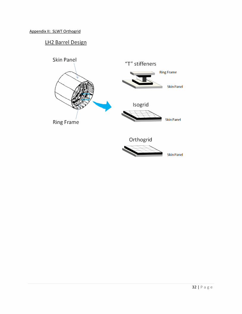
Requests for research material concerning the orthogrid portion of the proposal also found limited data available (Appendix III). An orthogrid design (a waffle-like grid) has never been flown on a propellant tank. However, McDonnell Douglas has published some research on similar isogrid designs (a triangular-shaped grid), which they have flown successfully. The upgrade from Al 2219 to the higher strength Al 2195 would allow the use of the orthogrid, which has fewer support beams (and thus less weight) than either the current “T stiffener” or isogrid designs. While there are still risks involved with the VOPS and TPS machining processes, both of these techniques are well-understood and the ET team seems unconcerned with any threats to the success of those modifications.
Overall, the ET team is extremely confident in the SLWT plan, noting that the proposal was drafted years ago and surely must be even more likely to succeed now. The suppliers are all reputable companies. The proposal offers delivery in 48 months, which would end exactly on the December 1997 target deadline. That does not leave any room for schedule slip, but Martin Marietta was able to produce the very first SWT from scratch on that same schedule. It would provide more than ETs “fair” share of mass reduction to the Space Shuttle. Could this be the solution for the ET?
November 1993
The Super Light Weight Tank Decision
The pressure has been building ever since the SRB Project Manager presented his plans for the ASRM. The ASRM proposal was rejected. Now, the Orbiter and ET will have to share the burden of reducing the 13,500 pounds without the help of the SRB. The success of ET Project’s proposal will be critical in determining the success or failure of the SSPs ability to support the ISS, since the Orbiter alone cannot account for that kind of weight savings. President Clinton has notified NASA that in one month, the United States, Canada, Japan, and European Space Agency intend on publicly announcing the formal invitation for Russia to join the ISS Program. Failure would result in global embarrassment and possibly even international hostility.
As the ET Project manager, you must present your plans for mass reduction to the SSP Office by the end of the week, and right now the SLWT is your only option. You will be expected to provide a deeper level of analysis for your proposal than simply your confidence level. You need to consider each aspect of the proposal and show that you have properly identified the risks specific to the suggested modifications, evaluated those risks against the perceived benefits, and made risk-informed decisions as to how to best proceed with reducing mass on the ET.
Mike Pessin: Video 3: The Proposal
We had to go in and make changes that were relatively massive (or very significant); and we had to come up with a test program for that – and still be able to fit that into the budget in the time available. Parker Counts: Fortunately, the contractor had done some research in aluminum-lithium; and that was a proposal that was there – while it had never been used in a space vehicle or space application – its properties are such that it gives you greater strength for less weight, so it became one of

9 | P a g e
the critical parameters that we looked at. And having had some initial work done on this was a benefit – so we had the aluminum-lithium as a material base to work from, as well as the corporate memory from all the original designers of the tank (both at Marshall and the contractor). So those things were a head start for us as we got into the super lightweight development. The second thing it contributed to the weight savings: was the decision that we made to go to an orthogrid structure as opposed to a skin stringer original to the tank design structure. What this allowed is that we could take – we could use a different pattern of orthogrid in the high-strength areas or the high-load areas, and then we could reduce it; so we were able to take advantage of machining it. Now it’s much more expensive: skin stringer panels are very clear, they’re simple, and they’re unique – they’re a standard design; where orthogrid has to be machined out in several patterns. And if you do that – then that’s a significant amount of cost increase to do the machine operations; and you lose about 85% of an original panel that you’re machining.
Mike Pessin: Video 4: Challenges
One of the changes that was made on super light tank was to go to a square waffle pattern instead of longitudinal Ts, this is known as an orthogrid. McDonnell-Douglas had flown isogrid (triangular patterns) on their Delta series launch vehicles; and they had done some research on the square waffle, but nobody had flown a square waffle on a pressure vessel. It had been used on payload shrouds, which are unpressurized. The timing of the proposal – Martin proposed four years – and this was questioned by the Level-2 folks, whether they could do it in four years. I brought out the point that the initial external tank was delivered in four years. Martin was given the contract in September of ’73 and delivered the main propulsion test tank in September ’77 – and that included going into an empty factory with no work force, no subcontractors, no design! And I felt that if they could do that in four years – they should be able to do a modification in four years. Martin had sold the production rights to this alloy to Reynolds Aluminum, and Reynolds started to try and make the alloy. The first lots they made did not have the same fractured toughness that the Martin material did – fractured toughness is the resistance to failure under a fracture kit condition, or resistance to tearing if you want to put it that way. So we went to Reynolds and said: “Why don’t you do a design of experiments?” and they said: “What’s that?” And we had to teach them how to do design of experiments. When the forming house tried to stretch-form the aluminum-lithium gores as opposed to the 2219 gores, they ran into problems. When they tried stretching the aluminum-lithium with the, in a T3 temper, it broke the stretch press; the films look like an earthquake, and the energy release almost took the roof off the building. So, the first step was: we had to learn how to form the parts; and this involved a rather radical change in the forming process. The general consensus was: that this was a viable candidate to go forward with – even though the material was very, very early in its development stage. Martin Marietta at one time had their own aluminum company; when they sold the company, they kept the R&D labs and recognized the need for a higher strength weldable alloy – so they were working on an aluminum-lithium family called Weldalite. This alloy was still in the labs and only a small amount had been made in the pilot plants, but the hope was that this material would be useful in our proposal.
10 | P a g e
If you want to go to TRL level – you know, Technology Readiness Levels – I never saw a number for this material. I don’t know what the TRL level was. But we had pretty good confidence that the material was going to be available. Going in – I guess from a personal standpoint – I didn’t know enough about it to be scared. But I think we certainly didn’t understand as much as we thought we did! Johnson waited 4 months before they turned us on, but kept the end date the same – so we were starting the program with a 44-month schedule instead of a 48-month schedule. Multiple weld repairs – it’s not unusual for them to crack – but these cracks are so wide open you could read a newspaper through them, and it was totally outside of any of our experience. So Martin decided to convene a giant meeting of all the welding people in the Martin corporate empire, which included Oakridge (they operated Oakridge), so they had a lot of experience in welding big nuclear containment vessels. They had people come in from a number of the different Martin organizations including Martin-Denver – who had built 300 Titans, welded 300 Titans, and we also brought in the Edison Welding Institute: • they’re the outfit out of Columbus, Ohio; • they’re the top welding people in the U.S.; • they maintain a total repository of all the welding data in the U.S.; and • they work closely with the British Welding Institute (who are some of the very top welding people in the world also). When we presented the data to them and they looked at it, they said: “You’re never going to learn to repair this material,” and we said “Can we change weld wires –well, a different weld wire (these are fusion welds, so they used a weld wire)?” and they said: “No, changing weld wires won’t help.” So: • we couldn’t make the material, • we couldn’t form it, and • we had great difficulty in repairing it, and • we had difficulty welding it. Now the last challenge we had to face is: that this material tends to be anisotropic. Anisotropic means that the material is not the same strength in all three axes: typically aluminums in the strength of rolling – in a rolling direction – have the highest strength; across rolling have a, which is known as the long transverse direction, have a lesser strength but still very high; and then through the thickness is the short transverse. Well, this material had an extremely low short transverse stress and it was more nearly equivalent to composites. Composites have a low short transverse stress, but the fibers in the composites don’t carry the load; whereas, the resin is what’s carrying the load in the short transverse. So we had to adapt the analysis techniques that had been developed for composites to use them on aluminum.

11 | P a g e
Exercises Introduction It is 1992; we are approaching the Preliminary Requirements Review (PRR) for the SLWT. As part of your briefing you must present the Directorate Top 10 Risk List (exercise #1). We then fast forward to the period of time between PRR and Preliminary Design Review (PDR). You are thrust into a number of key engineering management roles and challenged to develop risk control and mitigation plans for 5 of the most critical risks confronting the program. Formal Risk Statements are provided in each case as a point of departure for developing the risk burn-down plan. Let’s see how good you are at Risk Identification and the art of Risk Mitigation Planning. Risk Exercise #1: Risk Identification – You are the SLWT Program Manager Risk Exercise #2: Materials – Technology Maturity – You’re the Chairman of the Material Control Board Risk Exercise #3: Manufacturing - You are the Manufacturing Process Lead for MSFC Risk Exercise #4: Design Verification – You are the SLWT Chief Engineer Risk Exercise #5: Production Verification – You are the SLWT Systems Engineer Risk Exercise #6: Safety & Mission Assurance
– You are the SMA Manager on the SLWT
Reference: Space Shuttle Super Lightweight Tank, (SLWT), Independent Assessment of Risk Management Activities, NASA Office of Safety and Mission Assurance, December 12, 1997

12 | P a g e
RISK EXERCISE #1: Risk Identification
The Stage is Set: A Non-Advocacy Review approved of the SLWT plan, and the ET Project formally committed to reducing 7,500 pounds on the ET (which allowed for 500 pounds of margin, since the SLWT proposal outlined about 8,000 pounds of savings) for delivery in four years. Once the commitment was made to SSP, there was no going back, but the ET team was optimistic about their ability to achieve the mass savings in time to support the ISS assembly missions. Even when the actual start date for funding the SLWT was delayed by four months, the team was confident that they would be able to complete the new tank by the original deadline (the 48-month project now had to be completed in 44-months). And even though nearly the entire SLWT plan hinged on the successful production of the experimental Al 2195 material, ET engineers at MSFC were convinced that Al 2195 had matured enough as a technology to be ready to come out of the laboratory. The program knew that there would be both manufacturing and schedule risks but also believed that Martin Marietta had enough experience to successfully mitigate them. These were not perceived to be significant threats, since the partnership between MSFC and Martin Marietta had consistently surpassed expectations for both SWT and LWT.
> 20 Minute Team Activity
As the SLWT Program Manager you are responsible to brief your Top 10 Risk List at the Preliminary Requirements Review being held at NASA Headquarters in Washington, D.C.
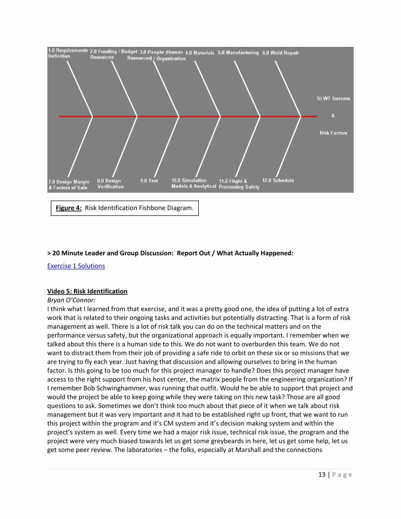
Team Notes / Starting Hints: You have pulled together a multi-disciplinary team of your managers at an off-site location. Using structured and unstructured brainstorming, populate a Risk Identification Fishbone (see example, Figure 4). The Fishbone Elements should include: Cost, Schedule, Technical, and Safety.
- You may add elements as your team deems necessary
- Circle the top 10 risks, and then rank order them
- Formulate risk statements for the top 3 using the syntax: “Given that A occurs, there is a possibility that B may result”
13 | P a g e
> 20 Minute Leader and Group Discussion: Report Out / What Actually Happened:
Exercise 1 Solutions
Bryan O’Connor: Video 5: Risk Identification
I think what I learned from that exercise, and it was a pretty good one, the idea of putting a lot of extra work that is related to their ongoing tasks and activities but potentially distracting. That is a form of risk management as well. There is a lot of risk talk you can do on the technical matters and on the performance versus safety, but the organizational approach is equally important. I remember when we talked about this there is a human side to this. We do not want to overburden this team. We do not want to distract them from their job of providing a safe ride to orbit on these six or so missions that we are trying to fly each year. Just having that discussion and allowing ourselves to bring in the human factor. Is this going to be too much for this project manager to handle? Does this project manager have access to the right support from his host center, the matrix people from the engineering organization? If I remember Bob Schwinghammer, was running that outfit. Would he be able to support that project and would the project be able to keep going while they were taking on this new task? Those are all good questions to ask. Sometimes we don’t think too much about that piece of it when we talk about risk management but it was very important and it had to be established right up front, that we want to run this project within the program and it’s CM system and it’s decision making system and within the project’s system as well. Every time we had a major risk issue, technical risk issue, the program and the project were very much biased towards let us get some greybeards in here, let us get some help, let us get some peer review. The laboratories – the folks, especially at Marshall and the connections
Figure 4: Risk Identification Fishbone Diagram.
14 | P a g e
they had across the country in this area, we would call them in and ask them to look at this problem and see if they could help us. I can tell you right now that there were two big times that we needed some extra help from peer review and so on. But that was not the only time that we did peer review and having outsiders come in and help us look it over. My memory says we had 50 or 60 if you add them all up from start to finish, independent reviews of one sort or another throughout this project. This team was not embarrassed to talk about their issues, claim their lack of understanding and asks for help. I think that is pretty key to success in a project. I have seen projects that were the other way. The kind that refused to admit that they had a problem, considered a peer review to be a last resort or a sign of weakness of some sort. That was not the case here. This team was very open to them and invited them. Brewster Shaw: Well there were the technical risks, the material itself, the material properties of the aluminum lithium material whether we were going to be able to weld it successfully, whether we are going to be able to do weld repairs, was it going to give us the strength criteria that we needed in order to get the weight savings that we needed to have, so they’re all the technicals, technical side, and of course can we do it for a reasonable budget and can we bring it on schedule to support the space station program, all the standard stuff, technical schedule and cost, there are risks in all of those categories, but they worked out alright because we used a rigorous process and the project used a rigorous process that they have documented for their project and we followed those and we did the work, we reviewed it on a regular basis, we pounded flat the problems and, you know, got the speed bumps out of the way and the project came in fine.

15 | P a g e
RISK EXERCISE #2: Materials – Technology Maturity Comparatively limited knowledge of 2195 material characteristics and weld ability (including repair) created a challenging development program. It was necessary to confront and address one technical issue after another, in parallel with design and manufacturing development activity. Risk Statement: Given that there exists insufficient knowledge and control of parent material (manufacturing variation and instability, fracture toughness and lowered properties in the short transverse direction), there is a possibility that NASA will be unable to construct a safe, verifiable SLWT. (Derived consequence – Failure to construct a viable SLWT would mean failure to achieve the necessary weight reduction to achieve the necessary up-mass to build the ISS at 51 degree inclination.)
> 20 Minute Team Activity: What would you do? > 20 Minute Leader and Group Discussion: Report Out / Leader Presentation of What Actually Happened
Exercise 2 Solutions
Video 6: Diligence
Team Tips / Starting Hints: First – relax, you don’t have to be a Materials Expert – most mitigation measures fall under a higher level set of “things that are viable” to drive down and control risk: Brainstorm ideas and development a risk control and mitigation plan. List the key elements on the flip chart provided. Consider (as a minimum): - Requirements (standards, rules, procedures) - Planning - Management Processes - Control Processes - Analysis - Testing (more than one flavor) - Experiments - Outside Help - Peer Review

16 | P a g e
Mike Pessin: The major thing is that: when you start a program, you need to do your due diligence and understand what you’re getting into. Here we were forced into this without doing the due diligence, without doing the advanced technology development because we didn’t have the time. But I know, I was in a meeting last Wednesday with the Ares V guys, or actually Glenn Research Center was down on composite structure and they were showing the technology development work they’re doing, so that to get themselves in a posture to go start designing the parts. And that’s I think, absolutely necessary. Particularly on Ares, where it’s just such a massive program that we need to provide the resources to this due diligence activity – you can’t do it on a shoe string: if you cut the budgets, if you don’t give the people the right test hardware, give them a chance to do the proper testing (on Shuttle we did a main propulsion test, I think we fired the vehicle 18 times, it was on a stand for 7½ years doing testing), and if you try and do that on a shoe string, it’s going to come back and bite you!

17 | P a g e
RISK EXERCISE #3: Manufacturing Every SLWT has over 3000 feet of welding. The weld land thickness ranges from t=0.140” to 1.00”. Three welding techniques are employed: (Gas Tungsten Arc Welding (GTAW), Variable Polarity Plasma Arc (VPPA), and “Soft” Plasma Arc (SPAW). With 3000 feet of weld, it is essential to assure that welds are free of defects which could become safety of flight issues. Weld repairs are frequent. The first SLWT will have on the order of 600 weld repairs. This is comparable to the number of repairs on the early 2219 External Tanks. The current weld repair rate on the 2219 tanks is on the order of 150 repairs per tank. Risk Statement: Given that ineffective or inconsistent welding and/or weld-repair methods result in flaws in the SLWT there is a possibility that the SLWT will fail catastrophically in flight. > 20 Minute Team Activity: What would you do?
> 20 Minute Leader and Group Discussion: Report Out / Leader Presentation of What Actually Happened
Exercise 3 Solutions
Parker Counts: Video 7: Manufacturing Issues
Team Tips / Starting Hints: First – relax, you don’t have to be a Welding Expert – most mitigation measures fall under a higher level set of “things that are viable” to drive down and control risk: Brainstorm ideas and development a risk control and mitigation plan. List the key elements on the flip chart provided. Consider (as a minimum): - Requirements (standards, rules, procedures) - Planning - Management Processes - Control Processes - Analysis - Testing (more than one flavor) - Experiments - Outside Help - Peer Review
18 | P a g e
One of the first problems and issues we had was: when we developed, when we had to go – (from the, we had developed the properties of aluminum-lithium at the small ingot level) to go to production yield – we had to increase that size of that ingot by several orders of magnitude. Second issue we had along those lines was: we had done a lot of research and a lot of study work on making the initial weld of aluminum-lithiums; so we could do those quite repeatedly at an initial state. What we had failed to realize is: that with an external tank having 36,000 inches of weld – that we’d have to do a lot of repairing; we have to repair a lot on the original material of 2219 aluminum. So we’d try to do our repairs, and we could not repair it Bryan O’Connor: The real issue here was material properties. Can we weld these things and will the welds stand up to inspection. Are we going to have a problem with good quality welds? Now that really should not be and wasn’t in my opinion, a flight safety issue because of the inspection. You know when you have a bad weld; you know when you have to go fix it. That was really more of a schedule issue than a flight safety one. The non-destructive evaluation techniques were very good, well known, well established and like I said, if you have a bad weld and you would see that then you would have to back and repair it or start over or whatever is appropriate. We felt when we got it ready to fly; we knew the welds were good. The material was good, the welds were good, and we understood the loads. The residual risk issues were minor when it comes to flight safety.

19 | P a g e
RISK EXERCISE #4: Design Verification Design verification concerns have been at the center of SLWT safety and risk management activities. The SLWT design verification approach operates from a bottom-up assessment of component failure modes and requires capability demonstration of each component, by test or linked to test data. In very few cases (e.g. LOX tank barrel, LOX tank aft to give, and aft end of intertank thrust panel)) this ground rule cannot be satisfied and design verification must be demonstrated through a combination of analysis, test, heritage (existing flight and test data), and simulation modeling. These three cases represented design and material changes where verification “by testing” was deemed unrealistic. The technical complexity and physical requirements of the test would have required time and resources unavailable to the SLWT program. Risk Statement: Given that design verification testing may not be adequate there is a possibility that the SLWT will buckle and fail catastrophically on the first flight. What would you do?
Exercise 4 Solutions
Brewster Shaw: Video 8: Documentation, Requirements, & Reviews
Team Tips / Starting Hints: First – relax, you don’t have to be a Systems Engineer – most mitigation measures fall under a higher level set of “things that are viable” to drive down and control risk: Brainstorm ideas and development a risk control and mitigation plan. List the key elements on the flip chart provided. Consider (as a minimum): - Requirements (standards, rules, procedures) - Planning - Management Processes - Control Processes - Analysis - Testing (more than one flavor) - Experiments - Outside Help - Peer Review

20 | P a g e
It was done in the standard way that we executed the program per 07700, which is the Bible for the Space Shuttle Program, that set of documents lays out exactly how you run out the program, who’s got the responsibilities, what the requirements are for the program, how level 1, level 2, level 3 relate to each other, how the information and command flows through the program, all the requirements for doing system integration reviews and all of the PRCB that the dailies, the nooners as they’re known as that kept the operations primarily in Florida flowing, and then the weekly PRCB where we made decisions about spending program money to do things like these performance enhancements and so we executed this project following the guidelines of 07700 and as we look forward into the program of Constellation and the way ESMD is setting that thing up, I highly recommend that we have an equivalent to 07700, that set of documents was created in 1973 for the Space Shuttle Program and still exists today, having been modified from time to time due to the environment and things that change, but having that Bible to go back to, to tell you how to execute the program and it talks about risk management specifically, having that to fall back on was an excellent way to manage a big, complex, high-risk program like Space Shuttle and like Constellation will be, so we followed the processes laid out in 07700 and we required of the project, the ET project that you have to have a project plan, you know, and you’ve got to do a systems integration review and we had periodic reviews with them on cost schedule and technical progress as we went through, we would review things, we had PRCBS on a weekly basis every Thursday and then about quarterly we would have a particular project review with each of the elements, the project elements of Shuttle, and during that time we spent a lot of that looking at the progress of super lightweight tank. So, requirements management, baseline configuration management, are extremely important. Requirements creep is a living thing in our programs and if you don’t keep it under control, it’ll ruin your program. It’ll eat up all the time and schedule you got. So you have to manage the requirements and requirements have to be flowed down from the top. You know, from level 1 they’ve got to say here’s what I need. Level 2 you tell me how you’re going to get it. And then, level 3, you tell me how you’re going to execute it. So, requirements management, baseline configuration management, once you get a design, if you let the design creep on you and you don’t have good baseline management of your configuration, you’ll get into a lot of trouble. You’ll lose track of that, you’ll lose track of your costs, you’ll lose track of your schedule and the program will go down the tubes. Parker Counts: The last count I had, we were somewhere around 60-plus independent reviews, so we didn’t shy away. I think the fact that, you know, we had the earlier problems – put us in a mode of: we don’t want to exclude any help we can get. So we called a lot of independent reviews on our own and then we had the normal independent reviews that NASA headquarters asked us to do, both financial and technical. And I think these reviews paid great dividends because we did not shortcut anything; we had safety and quality involved with us throughout the design and test of the program; and we ended up with a very solid weight savings and with a structurally sound tank – and I think time has proven – since we’ve been flying super lightweights since the mid-’98 timeframe, we’ve had no structural failures.

21 | P a g e
RISK EXERCISE #5: Production Verification In addition to the manufacturing process development issues identified above, and given the sensitivity of critical manufacturing processes, it is evident, that full scale production verification testing is important to assure the individual tank is free of defects. Risk Statement: Given that individual production SLWTs may have latent defects resulting from manufacturing escapes there is a possibility of catastrophic failure during operations What would you do?
Exercise 5 Solutions
Mike Pessin:
Video 9: Skunk Works
And we managed this like a Skunk Works. We had our key stress analysts, our key materials people, we had the key NASA people there – so for weld repairs, we had the Marshall welding guys; physically living down there, Fred Bickley, Kirby Lawless; and when an MRB had to convene, we had the NASA engineering people right there. The normal sequence is: • you have one government representative sitting on MRB,
Team Tips / Starting Hints: First – relax, you don’t have to be a Manufacturing Expert – most mitigation measures fall under a higher level set of “things that are viable” to drive down and control risk: Brainstorm ideas and development a risk control and mitigation plan. List the key elements on the flip chart provided. Consider (as a minimum): - Requirements (standards, rules, procedures) - Planning - Management Processes - Control Processes - Analysis - Testing (more than one flavor) - Experiments - Outside Help - Peer Review
22 | P a g e
• he calls back to Huntsville, • Huntsville does their thing, • and a week later you get an answer. And again on these technical issues, you might get a month review in Huntsville before you get a decision. Here we had the people sitting onsite, the people who you needed for the decisions. So the Air Force set up – what we call Skunk Works at Lockheed – and this technique gives you a certain amount of risk because you don’t get the multiple levels of review, but it gives you a virtually immediate response; and if you have the right people – and you’ve got to make sure you get the right people involved – it gives you a very efficient and streamlined program.

23 | P a g e
RISK EXERCISE #6: Safety & Mission Assurance You are now the Safety and Mission Assurance Manager on the SLWT Program. You have a broad range of concerns and a weighty responsibility. Risk Statement: Given that flaws exist in the design, design verification, manufacturing, or manufacturing verification of the SLWT then there is a possibility of catastrophic failure during operations What would you do?
Exercise 6 Solutions
T-20 seconds.
Video 10: First SLWT Mission
Parker Counts: We finished, I think if I remember right, from ATP to first flight was around 48 months; it’s an amazing schedule: once we accomplished it (once we got the problems worked through), we were able to get there. We had, at the beginning of the program, laid in an 8,000-pound tank; so I think this is one of the things that all programs can learn from: but we set an internal goal of 8,000 pounds – so we were
Team Tips / Starting Hints: First – relax, you don’t have to be a Safety & Mission Assurance Expert – most mitigation measures fall under a higher level set of “things that are viable” to drive down and control risk: Brainstorm ideas and development a risk control and mitigation plan. List the key elements on the flip chart provided. Consider (as a minimum): - Requirements (standards, rules, procedures) - Planning - Management Processes - Control Processes - Analysis - Testing (more than one flavor) - Experiments - Outside Help - Peer Review

24 | P a g e
striving to do 8,000. Now we succeeded with 7,500 plus; but at least we started with some margins, so we had some ability to redirect in some areas. From a cost perspective we were quite fortunate; because although we had had these original problems, we had a development budget of about $132 million. We were able to complete the project and still have $20 million in reserve.

25 | P a g e
EPILOGUE
A Non-Advocacy Review approved of the SLWT plan, and the ET Project formally committed to reducing 7,500 pounds on the ET (which allowed for 500 pounds of margin, since the SLWT proposal outlined about 8,000 pounds of savings) for delivery in four years. Once the commitment was made to SSP, there was no going back, but the ET team was optimistic about their ability to achieve the mass savings in time to support the ISS assembly missions. Even when the actual start date for funding the SLWT was delayed by four months, the team was confident that they would be able to complete the new tank by the original deadline (the 48-month project now had to be completed in 44-months). And even though nearly the entire SLWT plan hinged on the successful production of the experimental Al 2195 material, ET engineers at MSFC were convinced that Al 2195 had matured enough as a technology to be ready to come out of the laboratory. The program knew that there would be both manufacturing and schedule risks but also believed that Martin Marietta had enough experience to successfully mitigate them. These were not perceived to be significant threats, since the partnership between MSFC and Martin Marietta had consistently surpassed expectations for both SWT and LWT.
Within three months of beginning the SLWT project, sentiments underwent a complete reversal. Reynolds Aluminum could not reproduce the mechanical fracture properties cited in the Martin Marietta proposal data. Both the room temperature and cryogenic fracture toughness were significantly worse than predicted. At the specific cryogenic temperatures needed to store the LH2 and LO2, the Al 2195 was actually weaker than the Al 2219 used to make the LWT. Additionally, the mechanical properties data were extremely erratic. Reynolds Aluminum could not explain or resolve the differences.
At the same time, the project had been working on forming Al 2195 plates into the shapes needed to construct the ET. The Al 2219 forming process included cold working in a stretch press as a method of strain hardening and then aging at a specific temperature for strengthening. When the same procedure was applied to Al 2195, the stiffness of Al 2195 was actually so high that it destroyed the stretch press in a violent eruption. Because Al 2195 could not withstand the same temperatures as Al 2219, the aging process also resulted in an over-aged (and thus, weaker) material. This was all complicated Al 2195’s anisotropic mechanical properties, which the analytical models had not taken into account.
Welding presented yet another major challenge. As with Al 2219, it was common for weld shrinkage to cause cracking in the Al 2195 welds. In Al 2219, these cracks were small and could be easily repaired. However, with Al 2195, the weld repair process caused a phase change in the alloy’s microstructure that made the repair zone extremely brittle. Repeated repairs (as was commonly needed) would cause the entire zone to crack open. The first SLWT was estimated to need about 600 weld repairs, based on the number of repairs needed on the early ETs constructed with Al 2219. So the Edison Welding Institute, a consortium of welding experts from across the U.S., was tasked to evaluate the weld repair issue. They concluded that it would never be possible.
While a full test article was built, the structural verification plan did not initially intend to test every aspect of the new tank. It would mostly focus on the major redesigns like the orthogrid. Analysis was to be used, instead of testing, for the areas where only the margin was being reduced from the same basic design. An independent review of the structural verification plan found this strategy to be unacceptable. The review concluded that there was too much reliance on analysis over testing.
Given the needs of the Program, the Agency, and the country, failure was not an option. Each of these problems had to be solved on schedule and within budget. Key scientists and engineers were relocated

26 | P a g e
to the Michoud Assembly Facility in New Orleans. Contractors and civil servants worked together 12 hours a day for 7 days a week and were able to resolve each issue in turn over the next four years.
Reynolds Aluminum, Martin Marietta, and MSFC engineers had to perform a Design of Experiments (DOE) analysis. Since Reynolds Aluminum had never conducted a DOE, Martin Marietta and MSFC co-located their metallurgists and were eventually able to reproduce Martin Marietta’s original results. All plates of Al 2195 underwent a simulated service test, where two samples were cut from the ends of each plate: one was stressed to failure and the other underwent an intensive cyclic testing program.
Fracture Toughness
The Al 2195 was delivered from the manufacturer already having been tempered to be a stronger material. It was requested that it be delivered without the tempering so that it would no longer be too stiff for forming. The forming process then had to be reworked to include the tempers needed to strengthen the material. A new test program had to be established to determine the optimal aging temperatures and times for Al 2195. Analytical models were customized for the anisotropy based on previous ones built for composite materials.
Forming
It was discovered that Al 2195 needed to be welded with a backside purge of inert gas in addition to the front side purge used for Al 2219 and all other aluminums. Another technique used was to alternate repairing welds from the front versus backside on successive repairs. These changes required entirely new fixtures to support dual-side purge and repair. It was also found that the weld repair zone was reaching temperatures too hot for Al 2195. As welds were all made by hand, the welder’s torch speed had to be increased from 4 inches/minute to 10 inches/minute to achieve the desired temperature in the weld. The experienced welders were officially certified to 4 inches/minute and had great difficulty retraining their muscles to the new speed. In many cases, the inexperienced welders were more effective at welding at the new speed. By the end of development, the number of weld repairs needed was down from 600 to 150 per tank.
Welding
With the new weld fixture, the plasma torch was angled in such a way that the torch would blow out the melted aluminum puddle from its own weld. Therefore, a new welding technique had to be developed, which became another product of the successful collaboration between Martin Marietta and MSFC.
Testing
It took two months to redesign the structural verification plan around a test-based approach. SLWT now had to demonstrate capability through direct testing. There were three cases, however, where direct testing was not feasible due to available time and resources: LO2 Tank barrel, LO2 Tank aft to give, and Intertank thrust panel. For these cases, design verification was conducted through a combination of analysis, testing, heritage (flight and test) data, and simulation modeling. In addition, the safety factor for these components was increased to 2.0 and a second, independent analysis was required. This meant that there were now three different Factors of Safety (FoS) in use: 1.25 for areas with well understood loads, 1.40 for areas with less well understood loads, and 2.0 for areas not verified by direct test of capability.

27 | P a g e
Additionally, the full test article at flight pressure was compression loaded to failure. It was standard to compression load only to the required margin, but the SLWT tested to failure, which occurred at 200% of the design limit. This was well over the 140% requirement and certified the stability of the orthogrid.
Conclusion
SLWT completed successfully in time to support SSP missions to assemble the ISS and did so with $20 million in reserves. The total costs paid for the weight savings, including R&D and construction, was calculated to be about $10,000 per pound. SLWT was flown for the first time on STS-91 January 1998 and remains the current design for the ET. The SLWT was 7,500 pounds lighter than the LWT and passed all of the same performance and safety requirements. A final quantitative risk assessment of the SLWT calculated a slightly lower risk of structural failure than LWT.
Lessons Learned
Schedule pressures can deny the ability to conduct the ideal levels of due diligence, but risk management must be rigorous and pragmatic. The SLWT recognized that it was entering the project without the proper due diligence because the schedule mandated that the effort must proceed regardless. However, the project underestimated the risks and challenges to the success of the program. They did have the foresight to promise only 7,500 pounds when the plan involved 8,000 pounds of reduction to provide margin. But the project was overconfident in the readiness of the technology and had not thoroughly acknowledged the gravity of the technical risks involved.
(1) Technology Development Risk Reduction: Martin Marietta proposed the SLWT well before the capability was needed. While major assessments were denied funding, a preliminary review of the potential for using Al-Li alloy on the tank structure was funded through an Independent Research and Development special project. While not an extensive evaluation, it provided the basis of understanding for the redesigns proposed for SLWT. Having conducted the study years in advance of the need was integral in building the ET project’s familiarity and confidence in the option. Corporate memory became a double-edged sword during manufacturing. While retaining many of the original engineers from SWT and LWT provided invaluable expertise, it was found that many of the more experienced and highly trained welding technicians were unable to adjust their style and techniques to the new designs.
(2) Independent Reviews and Teamwork: SLWT underwent extensive independent reviews from numerous sources, including those external to the Project, Center, and Agency. The SLWT project was praised for its openness and responsiveness to the reviews. Many of the reviews were voluntary and requested by the Project itself. One of the great successes of the SLWT project was the extent to which the Agency and its contractors worked together. Many of the MSFC engineers were co-located with Martin Marietta and the other contractors at MAF for several years in order to work side-by-side and to resolve issues in real-time. Material Review Boards could be convened on the spot to deliberate in hours what would have taken days to accomplish.
(3) Systems Architecture: The vast majority of the weight savings for SLWT came from hardware redesign. It was stressed by the ET engineers and project manager that the initial design of the SSP was a highly coupled and sensitive architecture, making it very difficult and costly to make these hardware changes. A system that was not so highly coupled would have been more efficient for making upgrades or redesign.
28 | P a g e
(4) Dual Suppliers: It is important to assess the capabilities of the suppliers and manufacturers of critical materials. Reynolds Aluminum was the sole supplier of Al 2195 but was not the original inventor of the material. They had licensed the production rights and were initially unable to reproduce the advertised results. This was alleviated by the fact that the inventor (Martin Marietta) was also the prime contractor for SLWT. Eventually, as Al 2195 became an essential material for the ET, the project found it prudent to have Alcoa qualified as another supplier of Al 2195.
(5) Management Structure: It was ideal to separate the production team (which was allowed to focus on supplying the LWT for continuing SSP operations) from the development team (which could then concentrate on the SLWT) under one ET Project Manager, so that each team was not competing for the same resources.
(6) Careful Reduction of Margins: There are often places where margins can be reduced while maintaining the required Factor of Safety. These always represent areas for optimization, but it should be remembered that any form of margin reduction increases overall risk.
Video 11: Conclusions and Lessons Learned
Bryan O’Connor: When you talk about risk mitigation, one of the things I remember about this project and this team was that the project manager and his senior folks did not limit their brainstorming to themselves. A lot of times we will have a risk that pops up or we will identify a risk, maybe from a test failure, from some analysis that didn’t come out very well or a flight failure for flight type risks. We will get the team together to try to figure out what is the best way or what possible ways can we mitigate the risk. I think one of the limits that can limit you in your risk mitigation is not inviting enough people from enough levels to participate in that. I remember that one of the stories that came out of the welding issue, the risk that they had with welding the tig welds, the traditional welds on this new material, there was a fellow who was one of the welders, a non-degreed, non-engineer technician welder came up with what was the best mitigation in the end for this major project risk. He said, “If I move my torch a little faster, I get better results and maybe that is something we should plow into the procedures”. All the engineers sitting around the table there with Parker and Brewster and all of these other folks and Bob Schwinghammer and his guys may have come up with other things, but I do not know personally if they would have personally come up with what turns out and in retrospect sounds like a simple mitigation. Sometimes you get the best answer by going to the floor and talking to the folks with the wrench in their hand and the torch in their mitt that are actually doing the job. This was not unique to this project, it was actually a tradition at Marshall in what we used to call the PPIO Program and I can not remember what all that stands for but it was a way of getting all the players in a process or manufacturing activity, maybe even a design activity, to sit around the table and talk about what they do, where it does not work to well and how they might suggest to do it better – everybody, not just the engineer. I always thought that was a good lesson for me.

29 | P a g e
“When we as an Agency allow the politics and the budgets … to drive us to some of the things that we do, it entails risk. And … in the end, that is what the guys up at Headquarters and the Center Directors … they get paid for – is to balance that risk.”
Neil Otte Lead Structural Engineer, ET Project (during SLWT) Currently: Chief Engineer, Ares Launch Vehicle

30 | P a g e
REFERENCES
NASA Facts Super Lightweight External Tank (04/2005)
Independent Annual Review (IAR) for SLWT Program (10/07/1994)
SLWT Independent Assessment of Risk Management Activities (12/12/1997)
LWT / SLWT Delivery Option (08/11/1994)
Release: 96-144 Shuttle Super Lightweight Fuel Tank Completes Test Series (07/18/1996)
Release: 97-58 Shuttle's New Lighter, Stronger External Tank Completes Major Pressure Tests (03/28/1997)
Release: 98-6 New Space Shuttle External Tank Ready to Launch Space Station Era (01/15/1998)
Von Karman Lecture: The Space Shuttle - Some Key Program Decisions (01/12/1984)
Program Commitment Agreement SLWT (06/30/1994)
Lessons Learned: From Space Shuttle External Tank Development - A Technical History of the External Tank - (10/30/2002)

31 | P a g e
Appendix I: The Massiveness of the ET
Fun facts about the hugeness of the ET …
Fact #1- External Tanks are manufactured in New Orleans.
Eight external tanks were at the facility in New Orleans when Hurricane Katrina hit. A team weathered the storm with the tanks battling winds and flood waters, and had to use pumps to keep the facility dry. Following the storm, the facility became a base of operations for Katrina recovery efforts.
Fact #2 – The Tank was not always rust-colored.
The first two space shuttle missions, STS-1 and STS-2, were flown with an external tank which was painted white. Subsequent missions flew with unpainted tanks – saving approximately 600 pounds.
Fact #3 – The tank is as tall as the Statue of Liberty (without the base)
32 | P a g e
Appendix II: SLWT Orthogrid

33 | P a g e
Appendix III: SLWT Solutions – What They Actually Did
Exercise #1: Risk Identification Solutions
Narrative: Within three months of beginning the SLWT project, sentiments underwent a complete reversal. The project underestimated the risks and challenges to the success of the program. They did have the foresight to promise only 7,500 pounds when the plan involved 8,000 pounds of reduction to provide margin. But the project was overconfident in the readiness of the technology and had not thoroughly acknowledged the gravity of the technical risks involved.
Reynolds Aluminum could not reproduce the mechanical fracture properties cited in the Martin Marietta proposal data. Both the room temperature and cryogenic fracture toughness were significantly worse than predicted. At the specific cryogenic temperatures needed to store the LH2 and LO2, the Al 2195 was actually weaker than the Al 2219 used to make the LWT. Additionally, the mechanical properties data were extremely erratic. Reynolds Aluminum could not explain or resolve the differences.
At the same time, the project had been working on forming Al 2195 plates into the shapes needed to construct the ET. The Al 2219 forming process included cold working in a stretch press as a method of strain hardening and then aging at a specific temperature for strengthening. When the same procedure was applied to Al 2195, the stiffness of Al 2195 was actually so high that it destroyed the stretch press in a violent eruption. Because Al 2195 could not withstand the same temperatures as Al 2219, the aging process also resulted in an over-aged (and thus, weaker) material. This was all complicated Al 2195’s anisotropic mechanical properties, which the analytical models had not taken into account.
Welding presented yet another major challenge. As with Al 2219, it was common for weld shrinkage to cause cracking in the Al 2195 welds. In Al 2219, these cracks were small and could be easily repaired. However, with Al 2195, the weld repair process caused a phase change in the alloy’s microstructure that made the repair zone extremely brittle. Repeated repairs (as was commonly needed) would cause the entire zone to crack open. The first SLWT was estimated to need about 600 weld repairs, based on the number of repairs needed on the early ETs constructed with Al 2219. So the Edison Welding Institute, a consortium of welding experts from across the U.S., was tasked to evaluate the weld repair issue. They concluded that it would never be possible.
While a full test article was built, the structural verification plan did not initially intend to test every aspect of the new tank. It would mostly focus on the major redesigns like the orthogrid. Analysis was to be used, instead of testing, for the areas where only the margin was being reduced from the same basic design. An independent review of the structural verification plan found this strategy to be unacceptable. The review concluded that there was too much reliance on analysis over testing.
The actual project’s Top 3 Risk Topics at the start were:
#1. Technology Maturity: Achieving the Al-Li material properties enhancements.
#2. Design: Would the orthogrid design structurally hold.
#3. Design Verification: Analytical Verification vs. Physical Testing.

34 | P a g e
Three months into the project, they realized that their actual Top 3 Risk Topics were:
#1. Manufacturing: Weld repairs.
#2. Technology Maturity: Achieving the Al-Li material properties enhancements.
#3. Design Verification: Analytical Verification vs. Physical Testing.
Given the needs of the Program, the Agency, and the country, failure was not an option. Each of these problems had to be solved on schedule and within budget. Key scientists and engineers were relocated to the Michoud Assembly Facility in New Orleans. Contractors and civil servants worked together 12 hours a day for 7 days a week and were able to resolve each issue in turn over the next four years.
35 | P a g e
Exercise #2: Materials – Technology Maturity Solutions
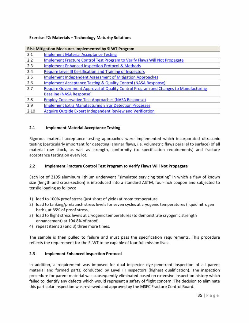
Risk Mitigation Measures Implemented by SLWT Program 2.1 Implement Material Acceptance Testing 2.2 Implement Fracture Control Test Program to Verify Flaws Will Not Propagate 2.3 Implement Enhanced Inspection Protocol & Methods 2.4 Require Level III Certification and Training of Inspectors 2.5 Implement Independent Assessment of Mitigation Approaches 2.6 Implement Acceptance Testing & Quality Control (NASA Response) 2.7 Require Government Approval of Quality Control Program and Changes to Manufacturing
Baseline (NASA Response) 2.8 Employ Conservative Test Approaches (NASA Response) 2.9 Implement Extra Manufacturing Error Detection Processes 2.10 Acquire Outside Expert Independent Review and Verification
2.1 Implement Material Acceptance Testing Rigorous material acceptance testing approaches were implemented which incorporated ultrasonic testing (particularly important for detecting laminar flaws, i.e. volumetric flaws parallel to surface) of all material raw stock, as well as strength, conformity (to specification requirements) and fracture acceptance testing on every lot. 2.2 Implement Fracture Control Test Program to Verify Flaws Will Not Propagate Each lot of 2195 aluminum lithium underwent “simulated servicing testing” in which a flaw of known size (length and cross-section) is introduced into a standard ASTM, four-inch coupon and subjected to tensile loading as follows: 1) load to 100% proof stress (just short of yield) at room temperature, 2) load to tanking/prelaunch stress levels for seven cycles at cryogenic temperatures (liquid nitrogen
bath), at 85% of proof stress, 3) load to flight stress levels at cryogenic temperatures (to demonstrate cryogenic strength
enhancement) at 104.8% of proof, 4) repeat items 2) and 3) three more times. The sample is then pulled to failure and must pass the specification requirements. This procedure reflects the requirement for the SLWT to be capable of four full mission lives. 2.3 Implement Enhanced Inspection Protocol In addition, a requirement was imposed for dual inspector dye-penetrant inspection of all parent material and formed parts, conducted by Level III inspectors (highest qualification). The inspection procedure for parent material was subsequently eliminated based on extensive inspection history which failed to identify any defects which would represent a safety of flight concern. The decision to eliminate this particular inspection was reviewed and approved by the MSFC Fracture Control Board.

36 | P a g e
2.4 Require Level III Certification and Training of Inspectors (see 2.3) 2.5 Implement Independent Assessment of Mitigation Approaches Aerospace Safety Advisory Panel: The ASAP provided periodic oversight of SLWT program developmental issues. The following quote and recommendations below provide insight to the rigor of the ASAP review activity: “The 2195 aluminum-lithium alloy used in the tank walls and domes of the new SLWT has lower fracture toughness at cryogenic temperatures than was anticipated in the design. To compensate for this potentially critical shortcoming, NASA has limited the pressure used in the full tank proof test and has recognized that the acceptance of each SLWT for flight is highly dependent on far more stringent quality control of the material and processes used to manufacture the SLWT than is required for the current external tanks.” ASAP Recommendation #16a “Assure that the acceptance tests for the 2195 material and the quality control procedures used in the manufacture of each SLWT continue to be sufficiently stringent, clearly specified, conscientiously adhered to and their use unambiguously documented.” 2.6 Implement Acceptance Testing & Quality Control The Space Shuttle Program (SSP) and MSFC agreed to ensure that material acceptance testing and quality control procedures used in manufacturing of SLWT’s are of sufficient quality to validate that each tank is fully in compliance with all program requirements and is safe to fly. ASAP Recommendation #16b “The criticality of these quality control operations makes it mandatory for NASA to retain buyoff of the results of those fabrication operations and tests that are essential in determining SLWT safety.” 2.7 Require Government Approval of Quality Control and Changes to Manufacturing Baseline (NASA Response) The SSP and MSFC agreed to retain approval of the quality control program and changes to that baseline. ASAP Recommendation #16c “As quality control data on the size of flaws detected in 2195 materials are collected, they should be used in an updated analysis of the SLWT structure, because it may permit the verifiable spread between flight limit stress and proof stress to be raised above that presently reported.”

37 | P a g e
2.8 Require Conservative Test Approaches (NASA Response) The simulated service database has been developed from data collected on fracture specimens with flaws which are 0.175 inch long. The data verify a 2.9 percent positive spread between the flight and proof-test conditions. Using the demonstrated flaw detectability level for our nondestructive evaluation dye penetrant process (0.086 inch long) would increase the spread to approximately 14 percent. Because of uncertainties, it is NASA’s standard policy to use a factor of two on our flaw detectability limit. This methodology provides the proper risk allocation between nondestructive evaluation capability and proof test levels. The use of a flaw size of 0.175 inch for the simulated service test is conservative for the SLWT. 2.9 Implement Extra Manufacturing Error Detection Processes The ASAP report continues: “NASA is taking extra precautions to assure that errors in manufacture can be detected. For example: Ultrasound: Each sheet and plate of procured 2195 aluminum lithium material is inspected by ultrasound at the vendor, where flaws as small as 0.047 inch can be detected and a flaw of 0.078 inch is cause for rejection. (OSMA Note: Any detectable flaw is cause for rejection). Dye Penetrant: Before and after forming, (OSMA Note: As mentioned above dye penetrant inspection is now performed only after forming) the entire surface of each tank element is subjected to dye penetrant inspection with two pair of experienced and qualified eyes looking for flaws. Flaws as small as 0.086 inch have been shown to be detectable. Any detected flaw is cause for rejection.” All ASAP recommendations have been fully implemented and members of the ASAP team supporting the SLWT Design Certification Review on September 28, 1997 expressed satisfaction that the design is safe and the program is prepared to proceed. It is worth emphasizing that ASAP has consistently voiced concern that the SLWT program must remain vigilant in assuring flight critical manufacturing process control (1996 Annual Report):
“Obviously, strict adherence to established procedures is required at every step of this process. Once successful, complacency cannot be tolerated in the production of subsequent tanks”
2.10 Acquire Focused Subject Area Independent Review and Verification The “SLWT Verification Team” was also been heavily involved in parent material issues. Chapter 2 of the Odom Report, (“Final Report of the Super Lightweight Mission Success Team” report, July 1994) is devoted to issues associated with parent material properties, in particular demonstration of Fracture Toughness Ratio (FTR); the ratio of cryogenic fracture toughness to room temperature fracture toughness. The Verification Team activity, extending from the Odom report, incorporated close partnership with the LM Fracture Control Board and the MSFC Fracture Control Board. These independent teams of technical experts provided close examination and rigorous scrutiny of all material acceptance rationale. The Verification Team documented and tracked safety and risk management issues and assured closure of any item affecting flight safety.

38 | P a g e
Exercise #3: Manufacturing Solutions
Risk Mitigation Measures Implemented by SLWT Program 3.1 Implemented Improved Weld Repair Strength Verification Testing 3.2 Introduced Planishing Weld Repair Requirements 3.3 Conducted Weld Repair Sensitivity Study 3.4 Developed Weld Allowable Data Base 3.5 Implemented Out-of-Family Weld Repair Testing Requirements 3.6 Implemented Wide Panel Testing Requirements 3.7 Introduced Reproof Test / Re-inspect Requirements After Repair Weld 3.8 Implemented Non-Conformance MRB Disposition Process 3.9 Implemented Defect Analysis, Evaluation and Acceptance Process 3.10 Implemented Independent Assessment of Mitigation Approaches
The SLWT program implemented a rigorous series of demonstration requirements for welding and weld repair processes involving the production of verification panels to demonstrate manufacturing capability and the fidelity of the completed weld or weld repair. 3.1 Implemented Improved Weld Repair Strength Verification Testing Initially, weld repair strength verification testing was conducted with one inch wide coupons (cut from the five inch long repair weld) pulled to failure to determine ultimate strength. As the SLWT development program evolved, other test data revealed that repair welds actually did not have the strength observed in the one inch coupon tests. Indeed, it was determined that residual transverse forces were “stored” in the weld due to solidification shrinkage, resulting in the weld repair being weaker than the initial weld. The one inch wide coupons, in effect, released the residual stress and consequently did not show degraded strength performance. In late 1994, the SLWT program initiated efforts to more accurately evaluate the global effects of a local repair. Subsequently, an effort was undertaken to increase the strength of the repair weld and establish a methodology and criteria for identifying acceptable weld repairs. 3.2 Introduced Planishing Weld Repair Requirements The program used the process of hammering (peening) or cold forming, referred to as “planishing” to flatten the weld repair geometry in a way that residual stresses were redistributed, thus eliminating localized areas of high residual tensile stresses. The program established a 70% to 110% target for recovery of shrinkage as an indicator of strength recovery. It was also observed that planishing “work hardened the joint” further increasing strength. 3.3 Conducted Weld Repair Sensitivity Study Recognizing the inadequacy of one inch coupons the SLWT program conducted a sensitivity study involving 150 to 200 “wide panel” tests each test using 19 inch wide panels, of a given thickness (variable), which were repair welded a certain number of times (variable), then planished to a particular degree of recovery (variable). Based on the sensitivity testing a “standard repair” was defined as a testing norm for use in developing the “weld allowable” data base. The standard repair was defined as a

39 | P a g e
five inch long, “R5” (where R5 indicates five repair welds, each one over the previous), in plate 0.32 inch thick and planished to a recovery value in the range 70% to 110%. The weld design value (“weld allowable”) program tested on the order of 600 to 700 wide panels, including specimens representing all thicknesses of welds in the tank and testing to failure for both room temperature and cryogenic test conditions. The baseline “standard repair” was uni-axially loaded to failure for statistical samples of 30, for room temperature, and 20 for cryogenic temperatures. These tests provided a reasonable statistical knowledge of the variation of repair weld strength performance (one standard deviation on the order of 2 ksi). Additional tests were then conducted with other thickness material with reduced sample sizes (n=5 to 10). This body of testing forms the “weld allowable data base”. 3.4 Developed Weld Allowable Data Base (see 3.3) 3.5 Implemented Out-of-Family Weld Repair Testing Requirements Weld repairs do not always conform to the criteria of “standard repair.” In some cases many more repairs are necessary or the length of the repair is longer than five inches, or planishing recovery is less than 70%. In such cases a sample of three wide panels are tested to failure to determine whether or not strength performance is within the range of the weld allowable data base. If this limited sample demonstrates similar strength values to the well characterized “weld allowable” population and the lowest test strength value meets or exceeds the appropriate weld allowable, typically on the order of 30 ksi (room temperature), then the weld repair is considered an in-family repair that is acceptable and safe. 3.6 Implemented Wide Panel Testing Requirements Wide panel testing used a fracture screening process similar to that employed in the parent material acceptance process. The testing protocol is designed to demonstrate that a detectable crack or flaw will not propagate under the stress of four simulated life cycles of tensile loading as described below: 1) load to 100% proof stress (just short of yield) at room temperature, 2) load to tanking/prelaunch stress levels for seven cycles at cryogenic temperatures (liquid nitrogen
bath), at 85% of proof stress, 3) load to flight stress levels at cryogenic temperatures (to demonstrate cryogenic strength
enhancement) at 104.8% of proof, 4) repeat items 2) and 3) three more times. The sample is then pulled to failure and must pass the specification requirements. This procedure reflects the requirement for the SLWT to be capable of four full mission lives. This testing demonstrates the ability of the panel to provide limit-load (plus margin) strength performance without cracking, with an induced reference flaw size.

40 | P a g e
3.7 Introduced Reproof Test / Reinspect Requirements After Repair Weld All repair welds are subjected to intense evaluation. Each repair weld is x-rayed at three different angles, and subjected to dye penetrant NDE inspection. Following these tests, the pressure vessel is proof tested to verify the acceptability of the tank. Then a final “targeted” x-ray inspection is conducted for historic problem areas, those areas of the tank not fully loaded during proof tests, all weld repairs, and all weld intersections to verify that the proof test did not “open up” any defects that were below the NDE threshold of detectability. Any out of specification condition is recorded in a Non Conformance Document (NCD) which requires material review board (MRB) disposition. The disposition must have the concurrence of NASA S&MA and NASA S&E. The weld repair risk mitigation process builds confidence that the completed SLWT has no unacceptable defects and is acceptable for flight. The SLWT program uses the “Defect Knowledge Base” as the central authority for deciding whether or not an observed defect is: 1) acceptable “as is”, 2) meets rigorously defined criteria to permit “in family repair”, or 3) represents something “out of family”, which requires testing and analysis sufficient to define a new weld repair protocol. The “Defect Knowledge Base” is then coupled to a multi-step verification process to assure the fidelity of weld repairs. 3.8 Implemented Non-Conformance MRB Disposition Process (see 3.7) 3.9 Implemented Defect Analysis, Evaluation and Acceptance Process An example of the rigor of the SLWT analysis and review process is the approach taken when two very small subsurface flaws (0.030” and 0.045”) were detected by X-ray on the ET97 LH2 tank after its final proof test. Repair and retest were considered, but the risk of two additional heat repairs was considered greater than the acceptance of these flaws. Before the flaws were considered for acceptance, a rigorous analysis was performed which showed that these flaws would survive over one thousand mission lives of seven propellant loading cycles and one flight loads cycle. For conservatism, the apparent radiographic flaw length was doubled for the analysis to compensate for the uncertainty involved in sizing flaws by X-ray. Since the program requirement is to be good for four mission lives, the capability of these flaws was more than 250 times the requirement. Further, the critical initial flaw size in the areas of each of the flaws is more than 10 times the apparent flaw length and this analysis was performed using a surface flaw rather than an imbedded flaw which is a more conservative approach. This determination was approved by the SLWT material review board, the LMC Fracture Control Board, and the MSFC Fracture Control Board which included representation from a JSC fracture control expert (Glen Ecord). The MSFC Fracture Control Board findings were documented to the project in their letter ED21 (ED25-97-73) dated October 30.

41 | P a g e
3.10 Implemented Independent Assessment of Mitigation Approaches Office of Safety and Mission Assurance OSMA supported all IAR activity and engaged the SLWT program in discussions concerning technical safety and risk management issues throughout the program life-cycle. One example of OSMA involvement in the area of weld repair was the SLWT consideration of options for addressing the problem of intersection cracks (IC) observed in certain weld configurations, a topic of review at the 1997 IAR. Based on OSMA concerns and the need for better understanding the intersection crack phenomena, a review was held at NASA Headquarters in June of this year. At the same time the SLWT program’s ongoing IC elimination initiative identified a potential solution. Testing showed that intersection cracking can be eliminated, almost entirely, through the substitution of 2219 ring frames for 2195 ring frames, and modifications to the welding techniques (dual cover vs. single cover weld passes and vertical, up oriented VPPA welding).

42 | P a g e
Exercise #4: Design Verification Solutions
Risk Mitigation Measures Implemented by SLWT Program 4.1 Introduce Higher Design Safety Factors 4.2 Require Conservatism in Test and Analysis 4.3 Acquire Independent Analysis Support 4.4 Design, develop, and manufacture a Test Article 4.5 Implement Component Test-to-Failure Program 4.6 Impose Rigid Materials Allowable Requirements 4.7 Conduct Modeling (NASTRAN) 4.8 Implement Proto-flight Testing of Each Tank 4.9 Characterize In-Family Behavior of Parent Material 4.10 Develop In-Family Weld-Allowable Database 4.11 Implement Demonstration Test 4.12 Implement Conservatism in Test and Analysis 4.13 Verify and Validate Models 4.14 Implement Multi-level Independent Assessment Processes
4.1 Introduce Higher Design Safety Factors For these cases, the safety factor was increased to 2.0 and a second, independent analysis was required. While extraordinarily rigorous, the “combination verification” sometimes complex rationale creates a dependency on fidelity of analyses, goodness of modeling assumptions, absence of unknown synergistic effects and applicability of component testing data. This concern is mitigated by the use of conservative considerations in analysis and test. This body of conservative practice is also summarized below. 4.2 Require Conservatism in Test and Analysis (see 4.1) 4.3 Acquire Independent Analysis Support LO2 Tank Design Verification: Complementary Test & Analysis Elements: The LO2 tank was verified using a combination of test and analysis. In order to mitigate potential tank buckling concerns designers decided to maintained the current structural ringframe stiffness. Component testing to failure was initiated for multiple sub-systems, such as the slosh baffle beaded web. The fidelity of several LO2 tank design elements was independently verified by analyses conducted at the Langley Research Center. The LO2 tank aft dome stability was verified in the Aluminum Lithium Test Article (ALTA) program. Other important elements in the overall design verification included the work to characterize the parent material properties and develop welding and weld repair allowable data bases. 4.4 Design, develop, and manufacture a Test Article (see 4.3)

43 | P a g e
4.5 Implement Component Test-to-Failure Program Intertank Design Verification: Complimentary Test & Analysis Elements The Intertank was also verified using a combination of test and analysis. In order to mitigate potential tank buckling concerns designers decided to maintain the current structural ringframe stiffness, thrust panel material and SRB beam design. Component testing to failure was initiated for multiple sub-systems, such as the skin stringer/joint, the beaded web, and the thrust panel. It is worth noting that early tests of the skin-stringer assembly resulted in skin buckling (prior to the required level), and led to design improvements which eliminated the problem. Independent analyses were conducted using the MSFC finite element stability model to verify aft thrust panel performance. The overall design was also supported by use of MIL-HANDBOOK 5 materials allowables information. 4.6 Impose Rigid Materials Allowable Requirements (see 4.5) 4.7 Conduct Modeling (NASTRAN) LH2 Tank Design Verification: Complementary Test & Analysis Elements Buckling rather than strength represents the biggest challenge for structural designers. Buckling and the resultant orthogrid delamination result from shear and compression loading of a structure with insufficient stiffness. The LH2 tank was verified using a combination of test and analysis. In order to mitigate potential tank buckling concerns designers decided to maintain the current structural ringframe stiffness. Component testing to failure was initiated for multiple sub-systems, such as the orthogid panel cryoflex tests in which bi-axial loads were introduced to assess stress concentrations and validate cryogenic performance of the NASTRAN structural design model. The ALTA program demonstrated the stability requirements for most of the LH2 tank barrels with the remainder being demonstrated by protoflight testing. In order to verify the design and production fidelity of LH2 tanks, the SLWT program will subject every production tank to a protoflight testing regimen which will demonstrate longeron stability and aft dome stability. Supporting the LH2 design verification is the previously cited work performed in parent material characterization and development of welding and weld repair allowable. 4.8 Implement Proto-flight Testing of Each Tank (see 4.7) 4.9 Characterize In-Family Behavior of Parent Material (see 4.7) 4.10 Develop In-Family Weld-Allowable Database (see 4.7)

44 | P a g e
4.11 Implement Demonstration Test Tanking/Detanking Test at KSC A test plan was developed to tank/detank the first SLWT with the primary function of providing a propellant loading demonstration. The resulting temperatures and pressures were monitored by KSC, including LM engineers. The results were correlated to the analytical Main Propulsion System predictions and the historical database. The six (6) ET/SRB struts were strain gauged to allow correlation of the “pinch load” values. 4.12 Implement Conservatism in Test and Analysis Conservative Assumptions and Philosophy to Offset Design Verification Complexity Analysis assumptions were made in a safety-conservative fashion employing the following: - Maximum loads were combined with maximum pressures to achieve a worst case; - Used limit/load pressures for pressure relieving scenarios, used limit minimum pressures for stability
calculations; - Used MIL HANDBOOK 5 “A Basis” assumptions (or NASA/MSFC) material property values; - Used minimum pressure vessel thickness for pressure vessel failure modes; - Used maximum drawing peaking/mismatch for generic weld analysis; - Used verified “equivalent cylinder”, which is conservative versus NASTRAN non-linear analysis for
failure modes; - Used maximum principal stress and not “Hencky Von-Mises” strength failure theory for flight
analysis. (Henky Von-Mises theory projects an increase in ultimate tensile strength when a structure is loaded in a bi-axial fashion)
Other examples of Conservative Design Engineering and Analysis - SLWT “Durability and Damage Tolerance” approach, set out in the MIL-Q-1530 specification assumes
a flaw exists in every structural component at a size just below the detection threshold of NDE capability with assumed worst case location and orientation.
- Tank is designed for 3-engine 106% power rating (as well as two engines at 109% for abort cases) aerodynamic and structural load environment.
- Factor of Safety (FOS) - FOS = 1.25 for areas on the tank where the load environment is well understood; - FOS = 1.40 for areas of the tank where the load environment is less well understood; - FOS = 2.0 for structural areas of the tank not verified by test. - 2195 aluminum lithium has approximately a 10% increase in stiffness at cryogenic
temperature and a fracture toughness ratio greater than 1.0. - The 115% structural verification protoflight test is conducted at ambient temperatures for
each tank. - 6'x6' flat plate cryogenic load testing is a “worst case” delamination scenario, as a curved
section would have greater resistance to orthogrid delamination.

45 | P a g e
4.13 Verify and Validate Models Verification of Analytical Models and Methods The success and safety of the SLWT is dependent on the accuracy and margin contained in analytical models and methodologies employed in the design process. The models and methods have been verified through, 1) comparison of model or method predicted structural response with measured structural responses from numerous test programs, 2) comparison of primary design model predicted response with predictions from other independent analytical models. Analytical Models and Methods The SLWT program employed a finite element analysis NASTRAN program to predict and analyze structural load distributions. Other analytical methods were used to predict buckling and ultimate failure (closed form or standard structural analysis techniques). The SLWT NASTRAN model is the same pedigree as models used throughout the external tank program life. NASTRAN model analyses correlated well with strain gauge data acquired in previous external tank development programs (Standard Weight Tank and Light Weight Tank). Building on this heritage of safety and mission success, the SLWT program set out to demonstrate the model’s ability to predict the load distribution throughout the redesigned tank structure for various loading cases and most importantly (along with other techniques described above), predict where and when a structure will fail for a given loading scenario. The SLWT NASTRAN modeling code and analysis techniques have been validated through extensive correlation of strain gauge measurement information acquired during 1) the Aluminum Lithium Test Article (ALTA) program, 2) during protoflight tests conducted with each LH2 tank, and 3) in component testing. Model/Method Verification through Test: ALTA In the case of the ALTA, over 700 strain gauges were deployed to acquire load distribution information through the various ALTA test scenarios including ultimate failure. The NASTRAN predicted load distribution correlated well with observations, falling within 5 % of measured strain gauge values in the regions of the test objectives. This conformity is considered excellent within the norm of structural design activity. The closed form cylinder analysis technique predicted the failure with an appropriately conservative margin. The model predicted failure at 126.5% of limit load, ultimate failure actually occurred at an equivalent load factor of 218%, following a period of extensive skin buckling and non-linear behavior. This degree of conservatism is appropriate when considering the non-linear and less well behaved mechanics of stability failure. Model/Method Verification through Test: SLWT-1 In the case of the SLWT-1 LH2 tank, loads were introduced for two protoflight loading scenarios, and 5 proof testing scenarios. Again, 700 strain gauges were deployed and measured induced loads which correlated extremely well with NASTRAN predictions, showing correlations, again within 5%.

46 | P a g e
Model/Method Verification through Test: Cryogenic Performance Test The cryogenic test panel behaved as predicted by the NASTRAN model, achieving agreement within 5% between strain gauge measurements and predicted response. Model/Method Verification through Test: Component and Coupon Testing Component testing “to capability”, was performed on 13 different subassemblies having either a design or material change, (e.g. intertank skin/stringer-joint compression tests, frame beaded web tests, and the “cryoflex” (cryogenic environments test). In each test, results showed article failure strength was well predicted by analytical techniques with some conservatism (e.g. 20-40% for beaded webs, 2-3% for intertank skin-stringer tests). There was however one test where the test article skin buckled which required a design change which subsequently passed the test. Welding and material qualification (pull to failure) testing results were also shown to agree well (20% conservatively) with BOSOR (buckling of shells of revolution) analytical predictions. Model/Method Verification through Comparison: Langley Research Center (LaRC) Finite Element Model Independent analytical models were used to validate the NASTRAN results in the three cases where combination analysis and coupon testing was used to verify structural integrity. A LaRC finite element model was used to validate the NASTRAN results for the LO2 tank barrel section and the LO2 tank aft to give assuring in each case, a Factor of Safety greater than 2.0. Model/Method Verification through Comparison: MSFC Finite Element Model The MSFC finite element analysis model was employed to verify predicted loads and capability of the intertank aft thrust panel. The two models (NASTRAN and MSFC finite element) agreed well and predicted structural Factors of Safety greater than 2.0. Environmental Loads Model (Load Sets) Space Shuttle Program Level II (Johnson Space Center) provides the SLWT program with Boeing North American (Rockwell) generated load sets. The SLWT program worked in an iterative process with Level II (sending the SLWT structural model to Downey to support system level loads calculations, receiving back the overall Shuttle system load environment, then refining the design as necessary to provide design margin, then sending the revised structural model back to Downey to support the next round of environmental load simulation.) The pedigree of the Level II environmental loads/ systems loads model is based on actual flight Orbiter strain gauge data, and early wind tunnel testing information. 4.14 Implement Multi-level Independent Assessment Processes Independent Assessment of Mitigation Approaches Verification Team Reviews Three principal technical review teams evaluated the early SLWT test and verification strategy. To a large extent, their activities were conducted in parallel which provided for constructive interaction and eventual synthesis of technical issues. An in-house, Martin Marietta review was conducted by former MMSS president Rick Davis during spring-summer 1994. Rick Davis strongly recommended conducting a full-up cryogenic test. Concurrently, a team led by Jim Odom was chartered to “assess the feasibility” of

47 | P a g e
the overall SLWT development program. A NASA MSFC Engineering review was conducted by Bob Ryan during the summer of 1994. This team developed an approach combining analysis and testing with rigorous modeling of performance. The Bob Ryan team interacted with both the Rick Davis and Odom teams, and worked closely with the SLWT program management team to develop the ultimate SLWT test and verification approach. An OSMA review led by Dan Mulville was conducted in the summer-fall 1994. The OSMA report concurred with the recommendations from the Odom and Davis teams to expand the planned structural verification activity. The “Verification Team” (follow-on for the Davis/Odom review activity) provided ongoing, in-depth technical review capability to the SLWT program. Based on a review of the proceedings of Verification Team presentations and discussions it was evident that the SLWT program is systematically involved in risk identification, risk ranking, and risk mitigation. For each safety of flight risk area, “ideas for risk reduction were collected and actions assigned to expand upon all ideas with promise.” The SLWT “Verification Philosophy” was hammered home time and time again. The philosophy was: - “Verify by test, for each structural element, the integrity of the structure; - Test can demonstrate structure will withstand ultimate loads, or test can demonstrate structure will
withstand limit load and validate analysis accuracy and conservatism used to extrapolate to ultimate load;
- Test can be omitted if FS greater than or equal to 2.0 (generally applied to secondary structure); - Test not required if similar, more critical, structural element has been test verified (i.e., gore panels,
barrel segments); - Test completion is precursor to flight or critical design condition (e.g., stacking, prelaunch, etc.); - Test articles will be built on production tooling with production processes; - Test articles will be fabricated from material acceptable for production hardware Deviations from above philosophy may be acceptable based on quantifiable rationale.” Verification Team meetings were thorough in their coverage of SLWT structural safety-of-flight issues, well documented, had clear conclusions and action items, and good follow-through from one meeting to the next. As discussed in introductory remarks concerning IA activity, the Verification Team was a real time risk management participant identifying and assuring satisfactory closure of issues. OSMA (Mulville) Review 1994 OSMA was asked by the Program Management Council to conduct an independent assessment of the SLWT design verification activity in mid-1994, leading to a report in November of that year. This report concluded that the current SLWT protocol met the intent of NASA policy but strongly urged that additional testing be incorporated to reflect structural performance at cryogenic temperatures. In a December 9, 1994 letter to Acting Deputy Administrator, the AA/OSMA said: “Although a full-up structural test article is not required, the opportunity to better demonstrate the performance of ‘as welded and repaired’ structure as proposed by the engineering change proposal now under consideration will further reduce program risk. Consequently we support the engineering change proposal’s (ECP) acceptance.”

48 | P a g e
The OSMA review team concluded the SLWT project test and verification plan would be acceptable “upon closure” of:
A. Material characterization B. Weld characterization C. Successful correlation of analytical modeling with:
1. Component coupon test data 2. Sub-assembly, Aluminum Lithium Test Article performance data (140% proof test, then test
to failure) D. Proof testing of the LO2 and LH2 tanks: a room temperature pressure proof test at an analytically
equivalent (adjusted) pressure of 105% of fracture basis limit load (production verification test) E. Protoflight testing of the LH2 tank: 115% static loads applied to Orbiter and Solid Rocket Booster
attach points (production verification test) F. Resolution of cryogenic loading concerns
The review team recommended that the Shuttle program evaluate the ‘desirability’ of instrumenting the first SLWT to determine pre-launch and/or flight loads. This non-safety-of flight recommendation was considered but ultimately set aside. The program decided against implementation based on strong confidence in the knowledge of the expected load environment and a belief that analytical modeling and tests have provided equivalent insight into flight load response. The review team also recommended considering a cryogenic impact assessment test proposed in a Martin Marietta ECP. This test involved bi-axial loading of a 6'x6' flat orthogrid plate at cryogenic temperatures. This test was designed to verify the performance of 2195 in the as welded and as-repaired configuration, as well as to verify adhesion of SOFI thermal insulation. Completion of this test was deemed desirable in order to reduce the risk associated with incorporation of new materials, design and fabrication methods in the SLWT. The cryoflex panel testing was, in fact, implemented and showed excellent agreement between the NASTRAN predicted load distribution and strain gauge measurements. All of the OSMA recommendations were implemented or accepted by OSMA as closed. ASAP Findings and Recommendations / SLWT Program Response The ASAP, led in its technical evaluation by Melvin Stone, took exception (1995 report) with the LO2 tank aft dome design verification approach: “The liquid oxygen tank aft dome gore panel thickness of the SLWT had been reduced significantly on the basis of analyses. To stiffen the dome a rib was added. The plan to verify the strength of the aft dome involved a proof test to only limit load. Buckling phenomena cannot be extrapolated with confidence between limit and ultimate load.” ASAP recommended that “the SLWT aft dome should either be tested to ultimate loads or its strength should be increased to account for uncertainties in extrapolation.” NASA agreed with the recommendation and added an aft dome test to the ALTA test program (successfully completed).

49 | P a g e
Exercise #5: Product Verification Solutions
Risk Mitigation Measures Implemented by SLWT Program 5.1 Subject Each Article to Static Load Test 5.2 Subject Each Article to Pressure Proof Test 5.3 Implement Comprehensive Non Destructive Evaluation (NDE) 5.4 Conduct Implement Independent Assessment of NDE Program
5.1 Subject Each Article to Static Load Test LH2 Protoflight Static Load Test Each production LH2 tank receives a prototype test which imposes 115% static limit load. The test verifies buckling stability. The loads are introduced at the Orbiter and Solid Rocket Booster attach points using worst case static load values. 5.2 Subject Each Article to Pressure Proof Test Each LH2 and LO2 tank undergoes a room temperature pressure proof test at an analytically equivalent (adjusted) pressure of 105% of fracture basis limit load. These tests provide an even higher strength verification and a flaw screen (fracture control acceptance test). The test process verifies weld integrity, fracture strength, and addresses workmanship issues. All welds not subject to operational load are x-ray inspected. 5.3 Implement Comprehensive Non Destructive Evaluation (NDE) Non Destructive Evaluation The SLWT program uses x-ray and dye penetrant testing and inspection (along with proof testing) as a means to verify the integrity of each SLWT pressure vessel. Process requirements are the most stringent possible. Parent Material Parent material NDE includes ultrasonic testing of all raw stock. LO2 Tank LO2 NDE activity includes: penetrant inspection of pressure vessel membrane, visual inspection, X-ray and penetrant of welds pre-proof, and X-ray of selected welds, weld intersections, and all weld repairs post proof. Intertank Intertank NDE includes: penetrant inspection of all formed parts, and visual inspection of assembled hardware.
50 | P a g e
LH2 Tank LH2 NDE involves: penetrant inspection of pressure vessel membrane, visual inspection, X-ray and penetrant of welds pre-proof, and X-ray of selected welds, weld intersections, and all weld repairs post proof 5.4 Conduct Implement Independent Assessment of NDE Program Independent Assessment of Mitigation Approaches Production verification independent assessment activity involved all of the various groups discussed above and overlapped in part with material acceptance activity and design verification as well as welding and weld repair. This specific area does provide an opportunity to highlight another key partner in the independent assessment process, the MSFC Science and Engineering Directorate. MSFC Science and Engineering Directorate Previous discussion of the MSFC Fracture Control Board recognized, in effect, the significant role of numerous experts in metallurgy, material properties, fracture mechanics, and test and evaluation. The nature of their “independence” was based in their professional adherence to their science, and unyielding technical rigor. Another “inside” but independent technical forum was the NDE community at MSFC. NDE issues were worked very hard at milestone reviews and were in fact outstanding issues of discussion, and eventual resolution, at the Design Certification Review.

51 | P a g e
Exercise #6: Safety & Mission Assurance Solutions
Risk Mitigation Measures Implemented by SLWT Program 6.1 Implement a System Safety Hazard Analysis 6.2 Design and Employ a Design Safety Checklist 6.3 Implement Safety Oriented Operations Readiness Reviews / Test Readiness Reviews 6.4 Conduct a SLWT Risk Quantification Using Probabilistic Risk Assessment Techniques
LM and MSFC have employed numerous management and engineering processes which provide an interlocking system of checks and balances to assure safety.
Other SMA Control and Mitigation Processes Implemented by NASA and LM MAF SMA Organizations (these are not indexed to text – only as processes)
P1 Requirements Documentation & Flow-down Process P2 Mission Success Communication Process P3 Program Review Processes P4 Program Control Processes P5 Personnel Certification Process P6 Hazard Analysis Process P7 FMEA-CIL Process P9 Technology Development & Verification: Parent Material Acceptance Process P8 Technology Development & Verification Process (Macro- Process) P10 Technology Development & Verification: Welding Process P12 Material Review Board Process P11 Technology Development & Verification: Weld Repair Process P15 Supply Chain Quality Management Process P14 Inspection & Surveillance Processes P13 Test & Verification Processes P16 MSFC Special Analysis & Review Assurance Processes P19 Flight Readiness Review and COFR Process P17 LM Special Analysis & Review Assurance Processes P18 Independent Assessment Processes
6.1 Implement a System Safety Hazard Analysis Michoud Space Systems’ Hazard Analysis process consisted of identifying potential hazardous conditions, developing controls to prevent the hazards, verifying the controls are in place, and documenting the results. The involvement of systems safety personnel in all phases of SLWT development and operation ensured timely identification and elimination/control of potential risks to personnel, property, and the environment within the constraints of cost, schedule, and program requirements. SLWT hazard analysis process relied on the established Space Shuttle Hazard Analysis process. SLWT hazards were reviewed by the System Safety Review Panel and entered into the ET Hazard Analysis Report following PRCB approval. Also, the Space Shuttle Critical Items List (CIL) was updated to include SLWT items.
52 | P a g e
6.2 Design and Employ a Design Safety Checklist Michoud Space Systems’ Design Safety Checklist is a practical and effective technique for the application of safety experience to the design and operation of hardware systems and equipment. The Design Safety Checklist assisted all disciplines in the application and retention of lessons learned; provided a management tool to coordinate the safety program; places safety in the mainstream of events; provided educational benefits to all disciplines; and provided a systematic method to identify hazards which can be used independently or in support of more sophisticated hazard analysis methodologies. 6.3 Implement Safety Oriented Operations Readiness Reviews / Test Readiness Reviews Michoud Space Systems’ Operational Readiness Inspection (ORI) program verifies the readiness of flight or test articles, facilities, tooling, procedures, and personnel to perform their specified operations. The ORI process is a formalized verification that any critical or potentially hazardous operation is ready to proceed. ORI reviews examine lessons learned, personnel qualifications and training, demonstrated process capabilities and most importantly process failure modes. The ORI process also serves to verify implementation of process fail-safing measures and other failure (and defect) prevention activities. The Test Readiness Review is a closely related preparatory exercise which works hand-in-hand with the ORI to assure the readiness of specific test program activities. 6.4 Conduct a SLWT Risk Quantification Using Probabilistic Risk Assessment Techniques As part of a larger project to develop the NASA Quantitative Risk Assessment System (QRAS), in 1997, MSFC SMA worked with the ET Project Office to update the 1995 SAIC probabilistic risk assessment (PRA) for the ET.

53 | P a g e
Appendix IV: Acronyms List (alphabetical order)
Al Aluminum
Al 2195 Aluminum-Lithium Alloy used on SLWT
Al 2219 Aluminum-Copper Alloy used on LWT
Al-Cu Aluminum-Copper Alloy
Al-Li Aluminum-Lithium Alloy
ASRM Advanced Solid Rocket Motor
ET External Tank
FoS Factor of Safety
ISS International Space Station
LH2 Liquid Hydrogen
LO2 Liquid Oxygen, a.k.a. LOX
LWT Light Weight Tank
MRB Material Review Board
MSFC Marshall Space Flight Center
NASA National Aeronautics and Space Administration
RTLS Return to Launch Site
SLWT Super Light Weight Tank
SS Space Shuttle
SSME Space Shuttle Main Engine
SSP Space Shuttle Program
SRB Solid Rocket Booster
STS Space Transportation System
SWT Standard Weight Tank
Ti Titanium
TPS Thermal Protection Shield
VOPS Variable Output Proportioning System