superstructure-based simultaneous optimization of heat...
TRANSCRIPT

Superstructure-based Simultaneous Optimization of Heat and Water Integration
Linlin Yang Advisor: Ignacio E. Grossmann
Department of Chemical Engineering Carnegie Mellon University
Pittsburgh, PA 15213
March 6th , 2011
Motivation
Water and energy are important resources in the process industries
Water issues Energy issues
Rapidly growing demand for freshwater Steadily growing demand for energy
All regions of the United States are vulnerable to water shortages
All regions of the United States are vulnerable to energy shortages
Environmental regulations for water discharge may require more energy
Meeting power plant emission standards requires more water
Need to lower intensity of water use Need to lower intensity of energy use
NETL - Technology Roadmap & Program Plan (2009) 2

Goal
To determine the flowsheet configuration and operating conditions that achieves optimal water and energy use to minimize cost
Two essential steps: 1. Determine the minimum freshwater flowrate (target) required for a
given set of water-using units Challenges: 1. Multi-contaminant water stream integration 2. Realistic wastewater system
2. Perform simultaneous optimization on heat and water integration of a process flowsheet
Note: only process flowsheet and HENS optimization has been performed (Duran and Grossmann, 1986)
3

Advantage
Captures tradeoffs among raw material, investment cost and operating cost
Cost
Overall conversion
raw material cost
Energy &water cost (sequential)
Total cost (sequential)
Energy &water cost (simultaneous)
Why simultaneous optimization?
4
Total cost (simultaneous)

Targeting approach
Determine a performance index ahead of detailed design of system configuration
Examples: Heat-exchanger network: heating and cooling utilities Water network: freshwater flowrate Distillation sequencing: recovery ratio
Advantages: Avoiding combinatorial problems Reduces problem dimensionality to a manageable size Offers insights into the system performance and characteristics
5

Levels of model complexity
Aggregated model (LP/NLP/MILP) e.g. Utility level
Transshipment model HENS/MENS (Papoulias, Grossmann, 1983; El-Halwagi, Maniousiouthakis, 1989)
Distillation Sequences (Papalexandri, Pistikopoulos, 1996; Caballero, Grossmann, 1999)
Reactor networks (Balakrishna, Biegler, 1992; Kravanja, Bedenik, Pahor, 2003)
Short-cut model (NLP/MINLP) e.g. Cost optimization
HENS: (Yee at al., 1990; Ciric and Floudas, 1991) Distillation sequences: (Aggrawal, and Floudas, 1990;
Yeomans and Grossmann, 1998) Process flowsheets: (Kocis and Grossmann, 1989; Türkay
and Grossmann, 1996; Lee et al, 2003)
Rigorous model (NLP/MINLP) e.g. Unit performance
Synthesis of distillation sequences Bauer, Stichlmair (1996,1998), Smith and Pantelides (1995), Yeomans, Grossmann (2000), Barttfeld, Aguirre, Grossmann (2004), Caballero, Milan-Yanez ,Grossmann (2005)
6
Minimum utility requirement
Not all models require a great amount of details!
Tubular Reactor
N2 H2
NH3
Purge
Multibed Reactor
Flash
Absorber
Membrane
Flash Condensation
Distillation
NH3
Water
Water
Distillation

Simultaneous flowsheet, heat, and water integration
7 Aggregated (LP)
Shortcut (MINLP)
Rigorous (MINLP)
Flowsheet
HEN
Water network
Path 1: Optimal solution (simultaneous optimization; MINLP)
Path 2: Can we avoid solving that MINLP but still get to the same optimal solution?
Path 0: Unrealistic

HEAT TARGETING
Proposed strategy – simultaneous integration
PROCESS FLOWSHEET
WATER TARGETING
Cold streams
Hot streams
MUC*
*MUC – minimum utility consumption
Hot utility
Cold utility
MUC*
Water streams
Wastewater
Freshwater
Utility networks
PROCESS STRUCTURE
WN STRUCTURE HEN STRUCTURE
PROCESS FLOWSHEET WITH HEN AND WN 8

Heat Integration – Targeting strategy
9
H1‐C 1
H1‐C 2
H2‐C 1
H2‐C 2
H1‐C 1
H1‐C 2
H2‐C 1
H2‐C 2
S tage 1 S tage 2
Temperature location k=1
Temperature location k=2
Temperature location k=3
s1
s 2
W1
W2
C 1
C 2
H1
H2
tC 1,1 tC 1,2 tC 1,3
tC 2,1 tC 2,2 tC 2,3
tH1,1 tH1,2 tH1,3
tH2,1 tH2,2 tH2,3
C oolersHeaters
Pinch Superstructure
- Linear formulation - Determines the minimum heating and
cooling requirement (targets)
- Difficult to solve (MINLP) - Determines the network structure

Conventional Water Network
10
Ahmetović and Grossmann(2009)
No reuse
Freshwater
Boiler Feedwater treatment
Steam System
Wastewater Boiler Blowdown
Steam Condensate Losses
Boiler
Water-using unit 1
Water-using unit 2
Water-using unit 3
Raw Water Raw Water Treatment
Wastewater
U"lity uses
Cooling Tower
Cooling Tower Blowdown
Water Loss by Evapora2on
Discharge
Wastewater Treatment
Storm Water
Process uses
Other Uses (Housekeeping)
Wastewater
No regeneration
reuse

11
Pinch
Process
Process
Treatment
Treatment
Freshwater
Discharge
Pinch Superstructure
- Linear formulation - Valid only for single-contaminant system
- Nonlinear network formulation - Valid for multiple contaminants
Water Integration – Targeting strategy

Proposed work - freshwater targeting
Relax nonlinear WN formulation into linear formulation Necessary condition of optimality (Savelski and Bagajewicz,2003)
“If a system is optimum, freshwater user processes have at least one component reaching its maximum concentration.”
The proposed LP model predicts the EXACT target for minimum freshwater consumption of a set of water-using processes Does not provide the network structure Accounts for process units that have water loss / gain No treatment unit included
12
Process unit 1
Process unit 2
Process unit 3
Freshwater Wastewater

Simultaneous optimization - example
13
+ cooling system + steam system Freshwater requirement
Heating requirement
Cooling requirement
methanol synthesis from syngas
Duran & Grossmann (1986); Turkay & Grossmann (1998)
Preliminary results – sequential vs. simultaneous comparison
14
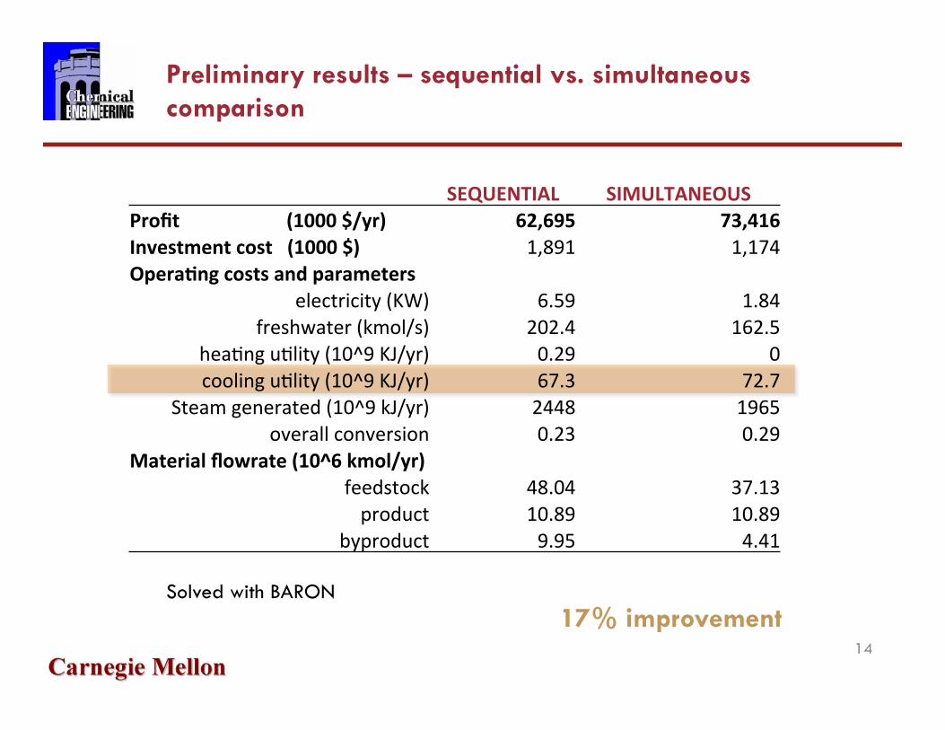
SEQUENTIAL SIMULTANEOUS Profit (1000 $/yr) 62,695 73,416 Investment cost (1000 $) 1,891 1,174 Opera"ng costs and parameters
electricity (KW) 6.59 1.84 freshwater (kmol/s) 202.4 162.5
heaKng uKlity (10^9 KJ/yr) 0.29 0 cooling uKlity (10^9 KJ/yr) 67.3 72.7
Steam generated (10^9 kJ/yr) 2448 1965 overall conversion 0.23 0.29
Material flowrate (10^6 kmol/yr) feedstock 48.04 37.13 product 10.89 10.89
byproduct 9.95 4.41
17% improvement Solved with BARON

Conclusion and future work
15
Conclusions: Developed water targeting formulation for water using units excluding
treatment units Developed targeting strategy for solving simultaneous flowsheet, heat and
water integration Captures tradeoffs between capital and operating costs
Future work: Water network
Non-isothermal water network Include wastewater treatment units
Thank you!

Heat Integration for PC Power Plant with CO2 Capture
16
Question: how to integrate the system to minimize power loss due to CO2 capture?
Steam cycle
Sorbent cycle
CO2 compression
NETL CCSI project

Heat Integration for PC Power Plant with CO2 Capture
17
Steam cycle
Sorbent cycle
CO2 compression
0
100
200
300
400
500
600
700
800
900
1000
0 200 400 600 800 1000 1200 1400
Temperature(°F)
Heat(MMBtu/hr)
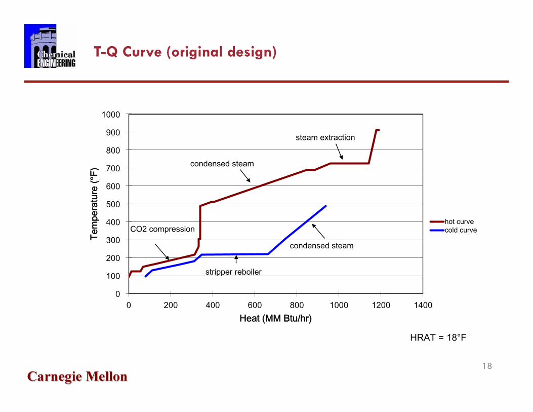
hotcurvecoldcurve
condensedsteam
steamextraction
CO2compression
stripperreboiler
condensedsteam
HRAT=18°F
T-Q Curve (original design)
18
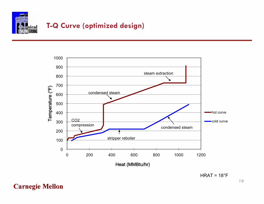
T-Q Curve (optimized design)
19
0
100
200
300
400
500
600
700
800
900
1000
0 200 400 600 800 1000 1200
Temperature(°F)
Heat(MMBtu/hr)
hotcurve
coldcurve
condensedsteam
steamextraction
CO2compression
stripperreboiler
condensedsteam
HRAT=18°F

H1
H2
H3
H4
H5
C1
C2
C3
262.2 92.7
218
723.5
124.6
724.5
148.7
488.4
123.6
723.5
180
488.4
219
128.4
94.4
218
179.4
471.4 144.6
163 146.7
184.1
109.7
165.7
H1 - CO2 compression streams H2 - stripper to absorber H3 – condensed steam extract IP-02 H4 - stripper condenser H5 – condensing steam extract IP-02
C1 - absorber to stripper C2 – boiler feed water C3 - stripper reboiler
Heat Exchange Network
20

Reference
Heat integration: Duran, M. A.; Grossmann, I. E. Simultaneous Optimization and Heat Integration of Chemical Processes. AIChE J. 1986, 32 (1), 123-138. Floudas, C.A. Nonlinear and Mixed-Integer Optimization: Fundamentals and Applications. Oxford University Press, 1995. Furman, K.C.; Sahinidis, N. A Critical Review and Annotated Bibliography for Heat Exchanger Network Synthesis in the 20th Century. Ind. Eng. Chem.
Res. 2002, 41, 2335-2370. Gundersen, T.; Naess, L. The Synthesis of Cost Optimal Heat Exchanger Networks. Comput. Chem. Eng. 1988, 12 (6), 503-530. Ježowski, J. Heat Exchanger Network Grassroot and Retrofit Design. The Review of the State-of-the-Art: Part I. Heat Exchanger Network Targeting
and Insight Based Methods of Synthesis. Hung. J. Ind. Chem. 1994, 22, 279-294. Papoulias, S. A.; Grossmann, I. E. A Structural Optimization Approach in Process SynthesissII. Heat Recovery Networks. Comput. Chem. Eng. 1983, 7
(6), 707-721.
Water integration: Ahmetović, E.; Grossmann, I. E. Global superstructure optimization for the design of integrated process water networks. AIChE Journal. 2010 Ahmetović, E.; Martín, M.; Grossmann, I.E. Optimization of Energy and Water Consumption in Corn-Based Ethanol Plants. Ind. Eng. Chem. Res. 2010. Bagajewicz, M.J. A review of recent design procedures for water networks in refineries and process plants.Comput.Chem. Eng.2000,24,2093-2113. Foo, D.C.Y. State-of-the-art review of pinch analysis techniques for water network synthesis. Ind. Eng. Chem. Res. 2009, 48, 5125-5159. Ježowski , J. Review of Water Network Design Methods with Literature Annotations. Ind. Eng. Chem. Res. 2010, 49, 4475–4516. Karuppiah, R.; Grossmann, I. E. Global optimization for the synthesis of integrated water systems in chemical processes. Comput. Chem. Eng. 2006,
30, 650-673. Mann JG, Liu YA. Industrial Water Reuse and Wastewater Minimization. New York: McGraw-Hill, 1999. Savelski, M. J.; Bagajewicz, M. J. On the necessary conditions of optimality of water utilization systems in process plants with multiple contaminants.
Chem. Eng. Sci. 2003, 58 (23-24), 5349-5362. Wang, Y.-P.; Smith, R. Wastewater minimization. Chem. Eng. Sci. 1994, 49 (7), 981-1006.
Others: NETL. EXISTING PLANTS PROGRAM: ENERGY – WATER R&D Technology Roadmap & Program Plan. 2009. Turkay, M.; Grossmann, I.E. Structural flowsheet optimization with complex investment cost functions. Comput. Chem. Eng. 1998, 22, 673-686.
21

NETL – “Water Requirements for Existing and Emerging Thermoelectric Plant Technologies “
Water Usage in PC Power Plant
Water consumption
22

Water network – problem statement
Given A set of freshwater sources with/without contaminants A set of water-using operations units and their inlet/outlet maximum
concentration level for contaminants A set of wastewater treatment units Maximum discharge contaminant concentrations
Determine Optimal water network
Minimize Freshwater consumption Annual cost of water network
23

Water targeting – pinch method for single contaminant system
Past works El-Halwagi and Manousiouthakis (1989) Wang and Smith (1994)
Comparison with heat pinch analysis Similarities: Heat pinch: heat load
Water pinch: mass load Heat pinch: Heating/cooling utilities
Water pinch: freshwater/wastewater flowrates Differences: Heat pinch: transfers heat only Water pinch: transfers MULTIPLE contaminants
Solution not rigorous
24
Need to find other method for freshwater targeting
Pinch

WN – superstructure-based method
Karuppiah and G. (2006); Ahmetović and G. (2009) Integrated water network with reuse, recycle, and regeneration schemes Constraints and objective functions are nonconvex Can determine global optimal solution with branch and bound algorithm
25
Process Unit
Process Unit
Treatment Unit
Treatment Unit
Freshwater
Discharge
Contaminants
Contaminants
Splitter
Mixer
Contaminants
Contaminants

HEN – problem statement
Given A set of hot process streams to be cooled A set of cold process streams to be heated Available utilities and their costs Heat recovery approach temperature (HRAT)
Determine Network configuration
Minimize Heating utility required Cooling utility required Investment cost of heat exchanger units
26

HEN – stage-wise superstructure
H1‐C 1
H1‐C 2
H2‐C 1
H2‐C 2
H1‐C 1
H1‐C 2
H2‐C 1
H2‐C 2
S tage 1 S tage 2
Temperature location k=1
Temperature location k=2
Temperature location k=3
s1
s 2
W1
W2
C 1
C 2
H1
H2
tC 1,1 tC 1,2 tC 1,3
tC 2,1 tC 2,2 tC 2,3
tH1,1 tH1,2 tH1,3
tH2,1 tH2,2 tH2,3
C oolersHeatersYee and Grossmann(1990)
Objective Function Min capital and utility costs
Constraints Overall energy balance for
each stream Energy balance for each stage Heating and cooling duties Logical constraints Temperatures differences
27

T-Q curve: Hohmann (1971); Linnhoff and Flower (1978)
Heating and cooling target – pinch analysis
Floudas (1995)
LP transshipment: Fixed F, T Papoulias and Grossmann (1983)
Pinch location method: Variable F, T Duran & Grossmann (1986)
900 kW
750 kW
28
Pinch
0),,( ≤CHHEN QQug