surge tank design considerations for controlling water ... ·...
TRANSCRIPT
University Bulletin – ISSUE No.15 – Vol . 3- 2013 - 147 -
Surge Tank Design Considerations for Controlling Water Hammer Effects at
Hydro-electric Power Plants Dr. Abdulghani RAMADAN
Dept. Of Mechanical Engin. Faculty of Engineering Al-Mergib University
Dr. Hatem MUSTAFA
Dept. Of Mechanical Engin. Faculty of Engineering
Zawia University
Abstract: A theoretical analysis based on some design considerations for
surge tanks is carried out. The effects of different parameters such as the friction losses coefficient and the surge tank cross-sectional area on the water surface oscillations tank and the total discharge are investigated. System of non-linear ordinary differential equations are numerically solved and manipulated. Results show that increasing cross-sectional area and friction losses coefficient results in decreasing the surge tank level and discharge rates. In addition, the height of the pressure waves and fluctuations that induced by the water hammer will be reduced and steadier. According to this study, the surge tank
Surge Tank Design Considerations for Controlling Water … ـــــــــــــ ـــــــــــــــــــــــ
University Bulletin – ISSUE No.15 – Vol . 3- 2013 - 148 -
dimensions could be estimated theoretically as follows; surge tank cross-sectional area is about 400 ~500 m2 which is corresponding to a first upsurge of about 3 ~ 4 m, respectively. Beside the above findings, cost, topography, location, operation conditions, type of equipments, load requirements, labour ...etc. should be also considered in the final design stage. Keywords: Hydraulic Transient, Hydropower, Surge tank, First upsurge, Water hammer. Introduction :
Surge problems are encountered in connection with unsteady state of flow of fluids in pipelines. In general a surge tank is designed to reduce the distance between the free water surface and turbine thereby reducing the water hammer effects on penstock and also protect upstream tunnel from high pressure rises. The other function is to serve as a supply tank to the turbine when the water in pipe is accelerating during increased load conditions and as a storage tank when the water is decelerating during reduced load conditions [1]. Fluid distribution systems and hydropower plants can be severely damaged by water hammer. Water hammer is the forceful slam, bang, or shudder that occurs in pipes when a sudden change in fluid velocity creates a significant change in fluid pressure. Water hammer can destroy turbo-machines and cause pipes and penstocks to rupture.It can be avoided by designing and operating these systems such that unfavourable changes in water velocity are minimized [2].
There are many methods that used to control the undesirable transients in pipeline systems and to reduce their negative effects. These methods are; bleeding in air directly into the pipeline, using noncircular conduits, using flexible hoses, air chambers, surge
ــــــــــــــــــــــــــــــــــــــــــــــــ Dr. Abdulghani RAMADAN & Dr. Hatem MUSTAFA
University Bulletin – ISSUE No.15 – Vol . 3- 2013 - 149 -
tanks, valving, valve stoking ...etc. Choosing one of these controlling methods is not arbitrary done, but it is based on the design criteria, conditions and system requirements such as location, topography and other factors that strongly affect the decision maker [2].
In the present study, Surge Tanks will be studied and analyzed. The effect ofvarying the friction losses and the surge tank area on the water surface oscillations in the surge tank and total discharge has to be investigated.
A FORTRAN 77 program is executed to run different data. The resulted output is closely investigated and graphically represented using EXCEL sheets. The numerical method, Runge-Kutta, is used to solve the set of non-linear, initial value, ordinary differential equations [3,4].
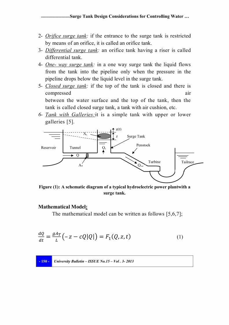
A surge tank is an open chamber, open standpipe or a tank connected to the conduits of a hydroelectric power plant or to the pipeline of a piping system, figure (1). The main functions of a surge tank are:
Reduces the amplitude of pressure fluctuations by reflecting the incoming pressure waves.
Improves the regulating characteristics of a hydraulic turbine because; it reduces the water starting time of a hydropower scheme.
Stores or provides water. The water in the pipeline is, therefore,accelerated or decelerated slowly, and the amplitude of the pressure waves in the system is reduced [5].
Depending upon its configuration, a surge tank may be classified as follows; 1- Simple surge tank:a simple surge tank is an open standpipe
connected to the pipeline.
Surge Tank Design Considerations for Controlling Water … ـــــــــــــ ـــــــــــــــــــــــ
University Bulletin – ISSUE No.15 – Vol . 3- 2013 - 150 -
2- Orifice surge tank: if the entrance to the surge tank is restricted by means of an orifice, it is called an orifice tank.
3- Differential surge tank: an orifice tank having a riser is called differential tank.
4- One- way surge tank: in a one way surge tank the liquid flows from the tank into the pipeline only when the pressure in the pipeline drops below the liquid level in the surge tank.
5- Closed surge tank: if the top of the tank is closed and there is compressed air between the water surface and the top of the tank, then the tank is called closed surge tank, a tank with air cushion, etc.
6- Tank with Galleries:it is a simple tank with upper or lower galleries [5].
Figure (1): A schematic diagram of a typical hydroelectric power plantwith a
surge tank. Mathematical Model:
The mathematical model can be written as follows [5,6,7];
= – 푧 − 푐푄|푄| = 퐹 (푄, 푧, 푡) (1)
z(t)
z
Q
Qtur
Qs
As
AT Tailrace
Reservoir Tunnel
Surge Tank
Penstock
Turbine
ــــــــــــــــــــــــــــــــــــــــــــــــ Dr. Abdulghani RAMADAN & Dr. Hatem MUSTAFA
University Bulletin – ISSUE No.15 – Vol . 3- 2013 - 151 -
= (푄 − 푄 ) = 퐹 (푄, 푧, 푡) (2)
푐 = (3)
where; 푄 is the total discharge = flow into the surge tank plus turbine flow = 푄 + 푄 , 퐴 is cross sectional area of the tunnel, 퐷 is tunnel diameter, 푍 is the water level in the tank above the reservoir level, 퐴 is cross-sectional area of the surge tank, 푘 is entrance loss coefficient, 푓 is friction factor, 푐 is a coefficient related to the hydraulic losses, 퐿 is tunnel length and 푔 is gravity. Solution Procedure :
The solution procedure is based on the numerical analysis scheme. In order to solve the above non-linear system of ordinary differential equations, the initial conditionscan be rewritten as follows;
For equation (1),푄(0) = assumed. For equation (2), 푍(0) = 0, 푄 (0) = 0 To find the solution of the system of equations (1), (2), the
Runge- Kutta (RK-4) method is used. The above equations are solved simultaneously.
A computer program is written in FORTRAN77 and compiled for various assumed data values under different design conditions. The program calculates the required parameters at each time step. For stability and convergence time step,∆푡, is specified.
EXCEL sheets are used to represent the output data graphically.
Surge Tank Design Considerations for Controlling Water … ـــــــــــــ ـــــــــــــــــــــــ
University Bulletin – ISSUE No.15 – Vol . 3- 2013 - 152 -
Results and Discussion: The results for different study parameters are obtained by
compiling the computer program. The data which used for this design analysis are: Q = 300 m3/s, L=500 m, AT=80 m2, Δt=0.5 sec (for stability). The effect of varying cross-sectional area of a surge tank, As, on the surge tank level, z.'.
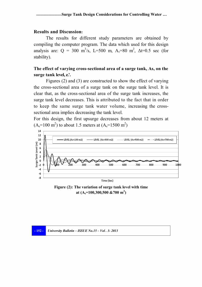
Figures (2) and (3) are constructed to show the effect of varying the cross-sectional area of a surge tank on the surge tank level. It is clear that, as the cross-sectional area of the surge tank increases, the surge tank level decreases. This is attributed to the fact that in order to keep the same surge tank water volume, increasing the cross-sectional area implies decreasing the tank level. For this design, the first upsurge decreases from about 12 meters at (As=100 m2) to about 1.5 meters at (As=1500 m2)
Figure (2): The variation of surge tank level with time
at (As=100,300,500 &700 m2)
ــــــــــــــــــــــــــــــــــــــــــــــــ Dr. Abdulghani RAMADAN & Dr. Hatem MUSTAFA
University Bulletin – ISSUE No.15 – Vol . 3- 2013 - 153 -
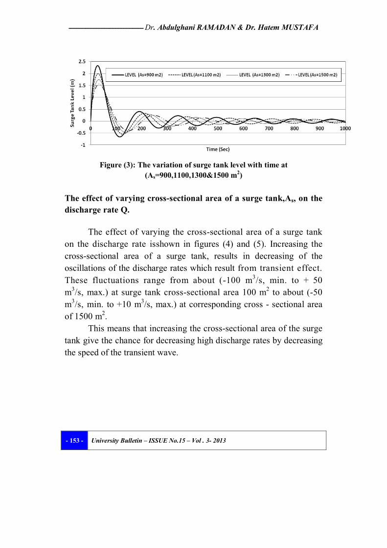
Figure (3): The variation of surge tank level with time at
(As=900,1100,1300&1500 m2) The effect of varying cross-sectional area of a surge tank,As, on the discharge rate Q.
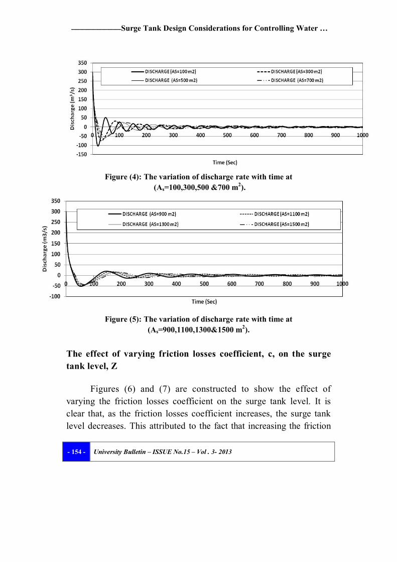
The effect of varying the cross-sectional area of a surge tank on the discharge rate isshown in figures (4) and (5). Increasing the cross-sectional area of a surge tank, results in decreasing of the oscillations of the discharge rates which result from transient effect. These fluctuations range from about (-100 m3/s, min. to + 50 m3/s, max.) at surge tank cross-sectional area 100 m2 to about (-50 m3/s, min. to +10 m3/s, max.) at corresponding cross - sectional area of 1500 m2.
This means that increasing the cross-sectional area of the surge tank give the chance for decreasing high discharge rates by decreasing the speed of the transient wave.
Surge Tank Design Considerations for Controlling Water … ـــــــــــــ ـــــــــــــــــــــــ
University Bulletin – ISSUE No.15 – Vol . 3- 2013 - 154 -
Figure (4): The variation of discharge rate with time at
(As=100,300,500 &700 m2).
Figure (5): The variation of discharge rate with time at
(As=900,1100,1300&1500 m2). The effect of varying friction losses coefficient, c, on the surge tank level, Z
Figures (6) and (7) are constructed to show the effect of varying the friction losses coefficient on the surge tank level. It is clear that, as the friction losses coefficient increases, the surge tank level decreases. This attributed to the fact that increasing the friction
ــــــــــــــــــــــــــــــــــــــــــــــــ Dr. Abdulghani RAMADAN & Dr. Hatem MUSTAFA
University Bulletin – ISSUE No.15 – Vol . 3- 2013 - 155 -
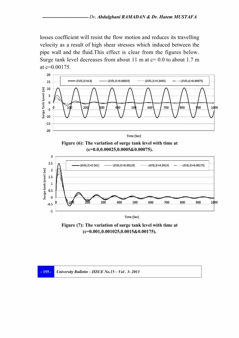
losses coefficient will resist the flow motion and reduces its travelling velocity as a result of high shear stresses which induced between the pipe wall and the fluid.This effect is clear from the figures below. Surge tank level decreases from about 11 m at c= 0.0 to about 1.7 m at c=0.00175.
Figure (6): The variation of surge tank level with time at
(c=0.0,0.00025,0.0005&0.00075).
Figure (7): The variation of surge tank level with time at
(c=0.001,0.001025,0.0015&0.00175).
Surge Tank Design Considerations for Controlling Water … ـــــــــــــ ـــــــــــــــــــــــ
University Bulletin – ISSUE No.15 – Vol . 3- 2013 - 156 -
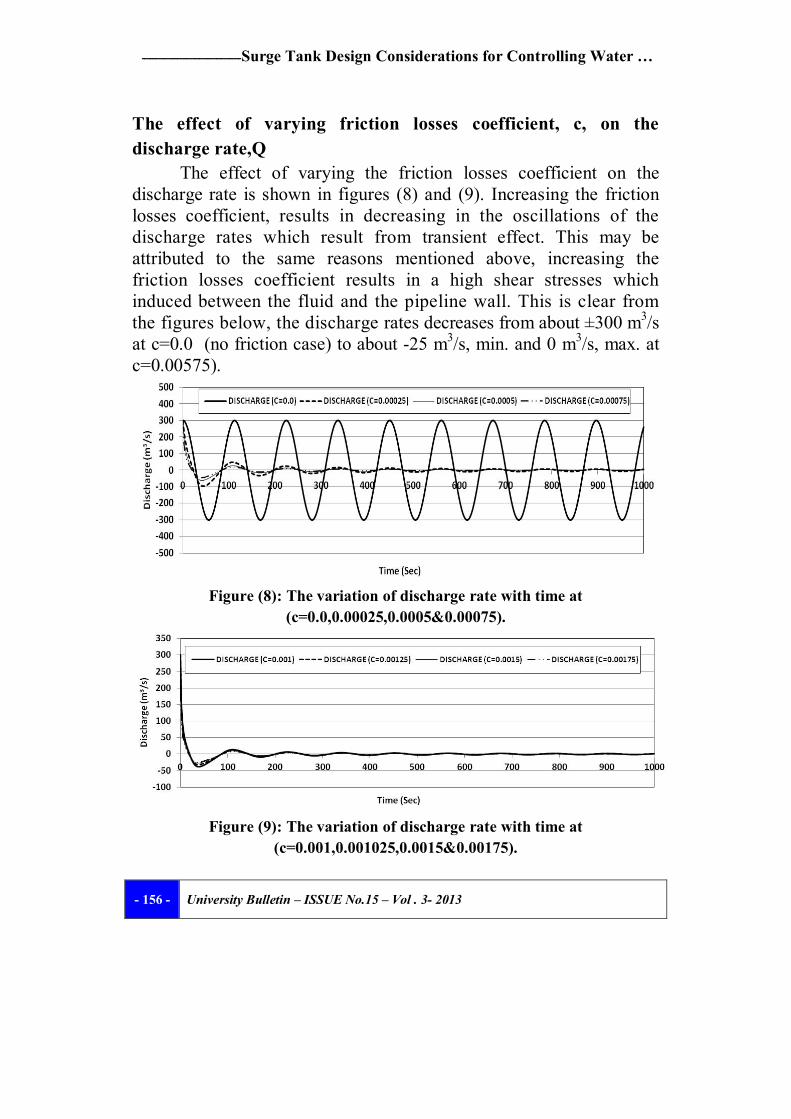
The effect of varying friction losses coefficient, c, on the discharge rate,Q
The effect of varying the friction losses coefficient on the discharge rate is shown in figures (8) and (9). Increasing the friction losses coefficient, results in decreasing in the oscillations of the discharge rates which result from transient effect. This may be attributed to the same reasons mentioned above, increasing the friction losses coefficient results in a high shear stresses which induced between the fluid and the pipeline wall. This is clear from the figures below, the discharge rates decreases from about ±300 m3/s at c=0.0 (no friction case) to about -25 m3/s, min. and 0 m3/s, max. at c=0.00575).
Figure (8): The variation of discharge rate with time at (c=0.0,0.00025,0.0005&0.00075).
Figure (9): The variation of discharge rate with time at
(c=0.001,0.001025,0.0015&0.00175).
ــــــــــــــــــــــــــــــــــــــــــــــــ Dr. Abdulghani RAMADAN & Dr. Hatem MUSTAFA
University Bulletin – ISSUE No.15 – Vol . 3- 2013 - 157 -
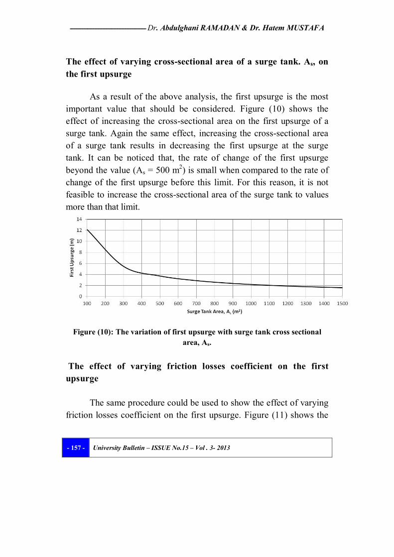
The effect of varying cross-sectional area of a surge tank. As, on the first upsurge
As a result of the above analysis, the first upsurge is the most important value that should be considered. Figure (10) shows the effect of increasing the cross-sectional area on the first upsurge of a surge tank. Again the same effect, increasing the cross-sectional area of a surge tank results in decreasing the first upsurge at the surge tank. It can be noticed that, the rate of change of the first upsurge beyond the value (As = 500 m2) is small when compared to the rate of change of the first upsurge before this limit. For this reason, it is not feasible to increase the cross-sectional area of the surge tank to values more than that limit.
Figure (10): The variation of first upsurge with surge tank cross sectional area, As.
The effect of varying friction losses coefficient on the first
upsurge
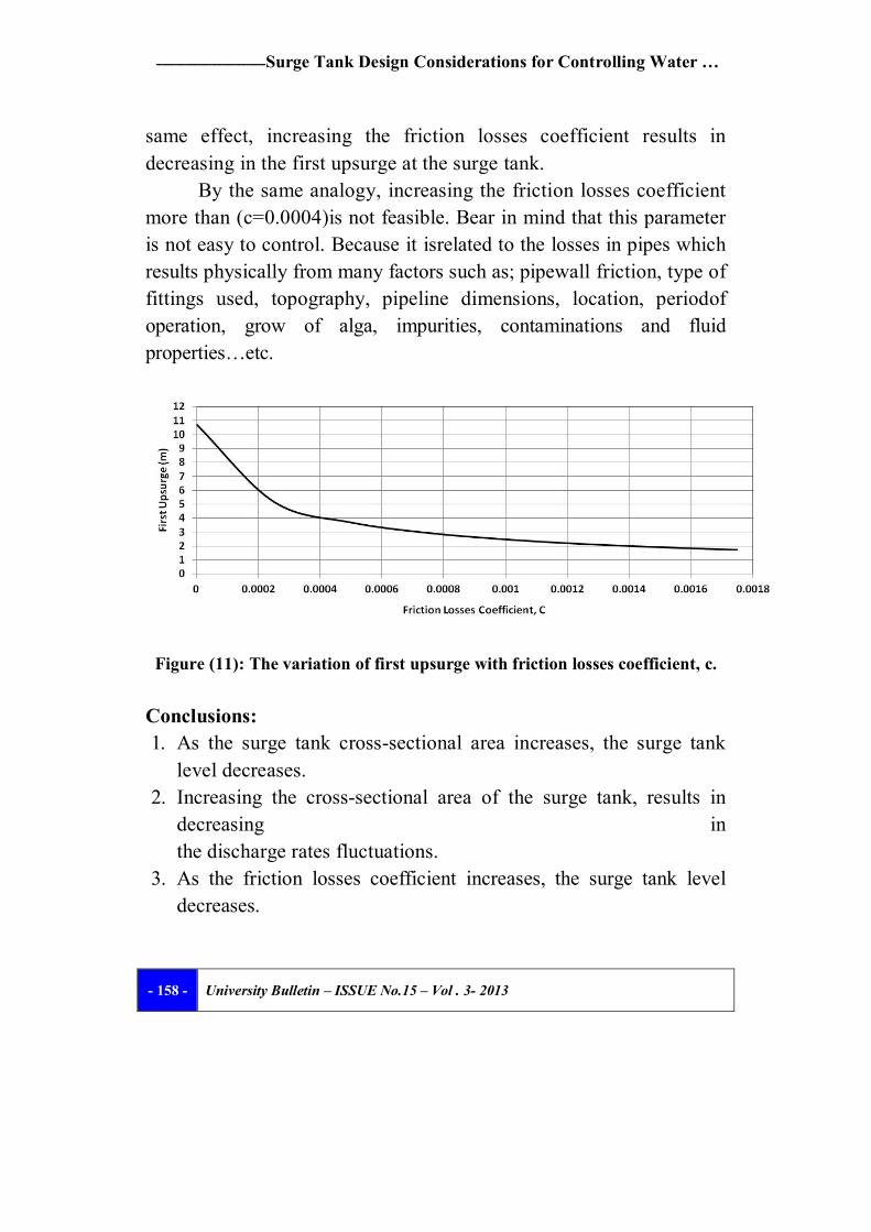
The same procedure could be used to show the effect of varying friction losses coefficient on the first upsurge. Figure (11) shows the
Surge Tank Design Considerations for Controlling Water … ـــــــــــــ ـــــــــــــــــــــــ
University Bulletin – ISSUE No.15 – Vol . 3- 2013 - 158 -
same effect, increasing the friction losses coefficient results in decreasing in the first upsurge at the surge tank.
By the same analogy, increasing the friction losses coefficient more than (c=0.0004)is not feasible. Bear in mind that this parameter is not easy to control. Because it isrelated to the losses in pipes which results physically from many factors such as; pipewall friction, type of fittings used, topography, pipeline dimensions, location, periodof operation, grow of alga, impurities, contaminations and fluid properties…etc.
Figure (11): The variation of first upsurge with friction losses coefficient, c. Conclusions: 1. As the surge tank cross-sectional area increases, the surge tank
level decreases. 2. Increasing the cross-sectional area of the surge tank, results in
decreasing in the discharge rates fluctuations.
3. As the friction losses coefficient increases, the surge tank level decreases.
ــــــــــــــــــــــــــــــــــــــــــــــــ Dr. Abdulghani RAMADAN & Dr. Hatem MUSTAFA
University Bulletin – ISSUE No.15 – Vol . 3- 2013 - 159 -
4. Increasing the friction losses coefficient, results in decreasing in the dischargerates fluctuations too.
5. The pressure wave amplitudes get smoother and steadier in shape as the surge tank cross-sectional area and friction losses coefficient increase.
6. The best preliminary design criteria for the surge tank dimensions could beestimated theoretically according to our results as follows; surge tank cross-sectional area is about (400 -500 m2). This corresponding to a first upsurge ofabout (4 ~ 3 m, respectively), taking into account the total losses between themain reservoir and the surge tank, the height of the surge tank could beroughly estimated as the sum of (the height of water column in the surge tank, the total losses between the main reservoir and the surge tank, the first upsurgeresult from surge tank area variation and the upsurge results from theeffect of friction losses coefficient) in addition to a factor of safety.
7. For the final design stage, many parameters should be taken into considerationsuch as; cost, topography, location, operation conditions, type of equipments, load requirements, labour, ...etc.
8. Field tests, close monitoring and supervision under different operation conditions for turbine namely, partial, full or critical load operation conditions should be carried out by using analog and digital computers. Readings and data obtained should be processed, analyzed and closely investigated. Proposals and recommendations about the final surge tank dimensions could be finally made and decided.
References : 1. R. K. Rajput,” A Textbook of Power Plant Engineering”, Lamxi
Publications Ltd,1st Edition,1995.
Surge Tank Design Considerations for Controlling Water … ـــــــــــــ ـــــــــــــــــــــــ
University Bulletin – ISSUE No.15 – Vol . 3- 2013 - 160 -
2. US Army Corps of Engineers, "Water hammer and Mass Oscillation", Construction Engineering, Research Laboratories, USACERL ADB Report 98/129, Sep- 1998.
3. S. C. Chapra and R. P.Canale," Numerical Methods for Engineers", McGraw-Hill, 2nd edition, 1988.
4. C. F. Gerald and P. O. Wheatley," Applied Numerical Analysis", Addison- Wesley, 3rd edition, 1984
5. M. HanifChaudhry," Applied Hydraulic Transients", Van Nostrand Reinhold, NewYork, 2nd edition, 1987.
6. GhulamNabi et al, “Hydraulic Transient Analysis of Surge Tanks: Case Study of Satpara and GolenGol Hydropower Projects in Pakistan”, Pak. J. Engg. & Appl. Sci. Vol. 8, pp 34-48, Jan., 2011
7. E. Benjamin Wylie and Victor L. Streeter," Fluid Transients", McGraw-Hill, 1978.