surgical echnique - suplemedicos | comercialización de ... for use fractures, fusions, and...
TRANSCRIPT

Forefoot/Midfoot Plating System
Surgical Technique
2
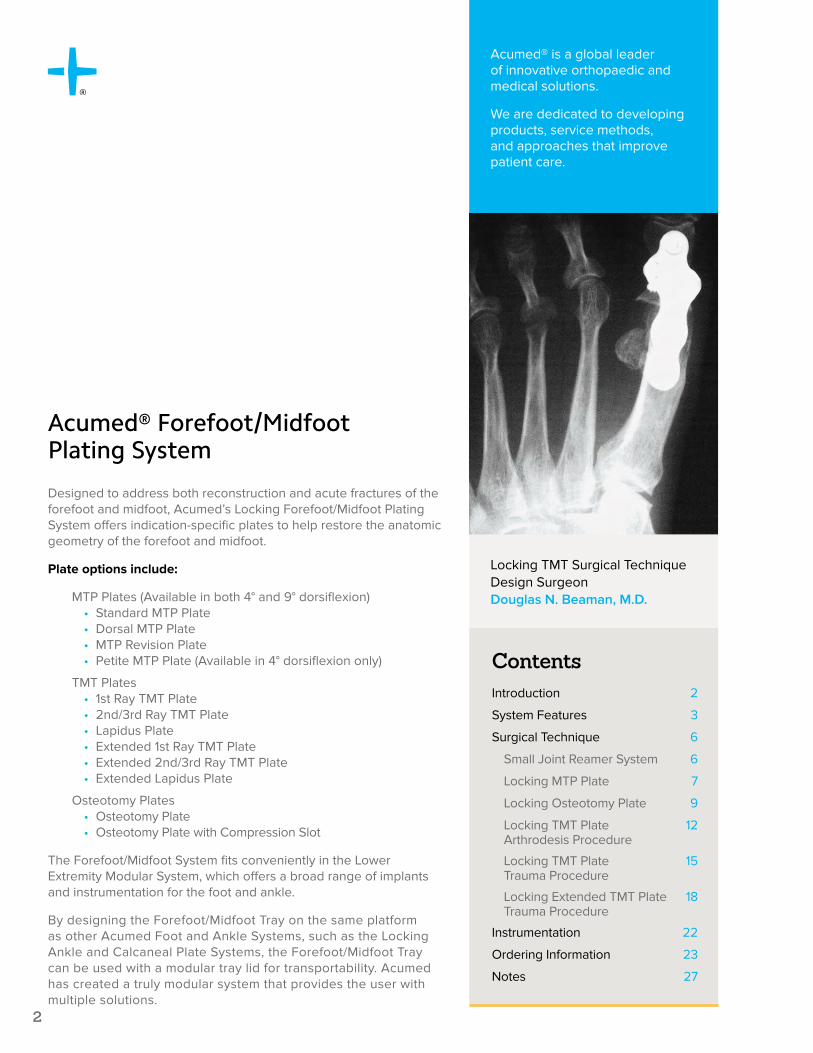
Designed to address both reconstruction and acute fractures of the forefoot and midfoot, Acumed’s Locking Forefoot/Midfoot Plating System offers indication-specific plates to help restore the anatomic geometry of the forefoot and midfoot.
Plate options include:
MTP Plates (Available in both 4° and 9° dorsiflexion)• Standard MTP Plate• Dorsal MTP Plate• MTP Revision Plate• Petite MTP Plate (Available in 4° dorsiflexion only)
TMT Plates• 1st Ray TMT Plate• 2nd/3rd Ray TMT Plate• Lapidus Plate• Extended 1st Ray TMT Plate• Extended 2nd/3rd Ray TMT Plate• Extended Lapidus Plate
Osteotomy Plates• Osteotomy Plate• Osteotomy Plate with Compression Slot
The Forefoot/Midfoot System fits conveniently in the Lower Extremity Modular System, which offers a broad range of implants and instrumentation for the foot and ankle.
By designing the Forefoot/Midfoot Tray on the same platform as other Acumed Foot and Ankle Systems, such as the Locking Ankle and Calcaneal Plate Systems, the Forefoot/Midfoot Tray can be used with a modular tray lid for transportability. Acumed has created a truly modular system that provides the user with multiple solutions.
ContentsIntroduction 2
System Features 3
Surgical Technique 6
Small Joint Reamer System 6
Locking MTP Plate 7
Locking Osteotomy Plate 9
Locking TMT Plate Arthrodesis Procedure
12
Locking TMT Plate Trauma Procedure
15
Locking Extended TMT Plate Trauma Procedure
18
Instrumentation 22
Ordering Information 23
Notes 27
Acumed® is a global leader of innovative orthopaedic and medical solutions.
We are dedicated to developing products, service methods, and approaches that improve patient care.
Acumed® Forefoot/Midfoot Plating System
Locking TMT Surgical Technique Design SurgeonDouglas N. Beaman, M.D.

3
Acumed® Forefoot/Midfoot Plating System Surgical Technique
System Features
Precontoured Plates are designed to match the anatomy of the patient. Based on multiple cadaveric and clinical trials, the MTP Plates are precontoured with both 4° and 9° of dorsiflexion and 10° of lateral translation to help restore the functional angle of the MTP joint after fusion.
Multiple Plate Options offer surgeons choices in forefoot/midfoot plating from an expanding line of MTP, TMT, and Osteotomy Plates.
Locking and Nonlocking Screws provide surgeons with the choice of:
• 2.7 mm hex screws• 3.0 mm hexalobe screws• 3.5 mm hex or hexalobe cortical screws• 4.0 mm cancellous screws
Indications for use
Fractures, fusions, and osteotomies of the foot including:
• Proximal metatarsal osteotomies• Osteotomies associated with Hallux Valgus correction• Fractures associated with Lis Franc injuries

4
Acumed® Forefoot/Midfoot Plating System Surgical Technique
System Featuresforefoot and midfoot plates
Blue plates are left specific, green plates are right specific, turquoise plates are neither right or left specific.
TMT Plates
9° MTP Plates
4° MTP Plates
Osteotomy Plates
5
Acumed® Forefoot/Midfoot Plating System Surgical Technique
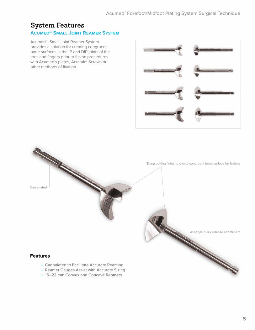
System FeaturesAcumed® Small Joint Reamer System
Acumed’s Small Joint Reamer System provides a solution for creating congruent bone surfaces in the IP and DIP joints of the toes and fingers prior to fusion procedures with Acumed’s plates, Acutrak® Screws or other methods of fixation.
Sharp cutting flutes to create congruent bone surface for fusions
AO-style quick release attachment
Cannulated
Features
• Cannulated to Facilitate Accurate Reaming• Reamer Gauges Assist with Accurate Sizing• 16–22 mm Convex and Concave Reamers

6
Acumed® Forefoot/Midfoot Plating System Surgical Technique
Small Joint Reamer System Surgical Technique
1 Open the joint and fully release the ligaments.
2 Using a K-wire Driver, insert the .062" Guide Wire (WS-1607ST) antegrade down the central axis of the distal phalanx. After placing the appropriate convex
reamer over the guide wire, use power to ream the distal fragment until the proximal end is denuded of cartilage.
3 Insert the second .062" guide wire retrograde up the proximal phalanx. Insertion should begin at the central axis and travel at the desired angle of flexion. Ream
the proximal phalanx over the guide wire using the same size concave reamer used in Step 2. Ream until the distal end of the phalanx is denuded of cartilage.
4 Fit the phalanges together in the desired flexion and fix with an Acumed MTP Plate (70-0XXX) or with an Acutrak 2® Headless Compresssion Screw (AT2-5XX).
7
Acumed® Forefoot/Midfoot Plating System Surgical Technique
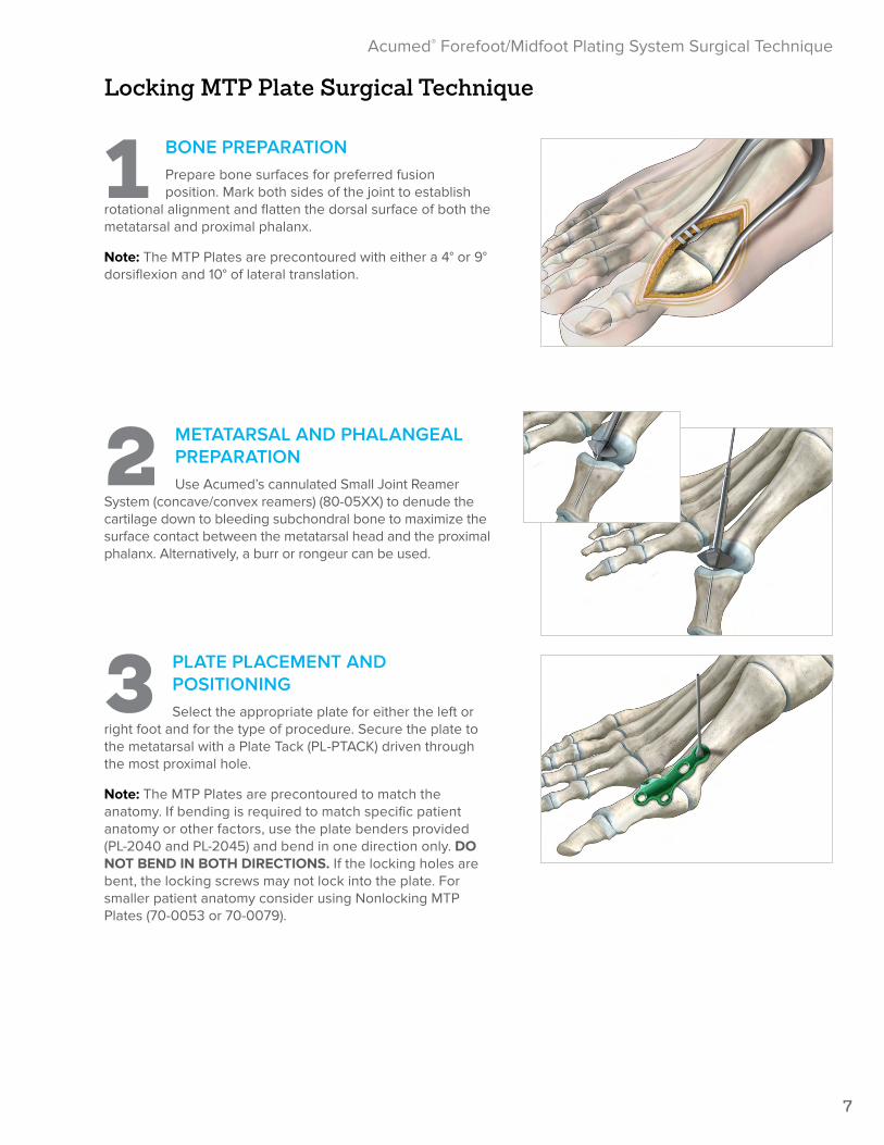
1 BONE PREPARATIONPrepare bone surfaces for preferred fusion position. Mark both sides of the joint to establish
rotational alignment and flatten the dorsal surface of both the metatarsal and proximal phalanx.
Note: The MTP Plates are precontoured with either a 4° or 9° dorsiflexion and 10° of lateral translation.
2 METATARSAL AND PHALANGEAL PREPARATIONUse Acumed’s cannulated Small Joint Reamer
System (concave/convex reamers) (80-05XX) to denude the cartilage down to bleeding subchondral bone to maximize the surface contact between the metatarsal head and the proximal phalanx. Alternatively, a burr or rongeur can be used.
3 PLATE PLACEMENT AND POSITIONINGSelect the appropriate plate for either the left or
right foot and for the type of procedure. Secure the plate to the metatarsal with a Plate Tack (PL-PTACK) driven through the most proximal hole.
Note: The MTP Plates are precontoured to match the anatomy. If bending is required to match specific patient anatomy or other factors, use the plate benders provided (PL-2040 and PL-2045) and bend in one direction only. DO NOT BEND IN BOTH DIRECTIONS. If the locking holes are bent, the locking screws may not lock into the plate. For smaller patient anatomy consider using Nonlocking MTP Plates (70-0053 or 70-0079).
Locking MTP Plate Surgical Technique

8
Acumed® Forefoot/Midfoot Plating System Surgical Technique
4 INITIAL SCREW PLACEMENTPlace selected Locking Drill Guide (for hex 80-0384, for hexalobe 80-0668 or 80-0622) into
the distal hole of the plate and drill through both cortices. Use the Depth Gauge (MS-9022) to determine the screw length. Choose the appropriate size screw and insert into the bone. A nonlocking cortical screw can be used to pull the plate to the bone.
Note: Select the screw diameter based upon the patient’s anatomy. The 2.0 mm Drill (80-0386) is used for the 2.7 mm screws and the 2.8 mm Drill (80-0387) is used for the 3.5 mm hex or hexalobe and 4.0 mm screws. The 2.3 mm Drill (80-0627) is used for the 3.0 mm hexalobe screws.
5 COMPRESSION OF FUSION SITEPlace the gold end of the Offset Drill Guide (PL-2095) into the plate’s compression slot with
the arrow on the guide pointing toward the fusion site. Drill and measure for screw length. Insert the appropriate size nonlocking screw to apply 1 mm of compression to the fusion site.
Note: For hard bone, 2.7 mm and 3.5 mm Bone Taps (MS-LTT27 and MS-LTT35) are recommended.
6 INSERTION OF REMAINING SCREWSPlace selected locking drill guide into the distal medial and lateral holes and drill. Measure and
insert locking cortical screws. Remove plate tack from the most proximal hole and use the same screw insertion process. The nonlocking cortical screw in the distal hole may be replaced with a locking cortical screw at the surgeon’s discretion.
Note: Screws are single use devices and must not be reused. If a screw is inserted for provisional fixation and then removed, it must be discarded to prevent reuse.
7 POSTOPERATIVE PROTOCOLThe foot is protected with a postoperative shoe and dressing. The patient is allowed to proceed with
weight-bearing activities as determined by surgeon.

9
Acumed® Forefoot/Midfoot Plating System Surgical Technique
HALLUX VALGUS CORRECTION
The proximal osteotomy of the first metatarsal is used in conjunction with a distal soft tissue correction of the hallux valgus deformity. It is usually indicated when the first metatarsal and second metatarsal angle is greater than 15°.
FIRST METATARSAL OSTEOTOMY EXPOSURE
The osteotomy site is exposed through a dorsal incision 1.5" to 2" in length over the dorsum of the base of the first metatarsal. Care is taken to preserve the extensor tendons and small cutaneous nerves and vessels in this area. The periosteum over the base of the first metatarsal is opened and elevated, and the first metatarsal joint is identified.
OSTEOTOMY PROCEDURE
The osteotomy is positioned approximately 1 cm distal to the first tarsal-metatarsal (TMT) joint, and is made slightly oblique from perpendicular to allow more room for the placement of the proximal screws. The concavity of the osteotomy is positioned facing towards the first TMT joint.
ANGLE CORRECTION
The angle between the first and second metatarsal is decreased with the aid of a retractor. The retractor is placed laterally over the proximal fragment pulling the distal end of the proximal fragment into a more medial position while lateral compression is placed across the distal fragment of the first metatarsal. The corrected position of the first metatarsal is then maintained with K-wire fixation. A .062" (WS-1607ST) K-wire is placed across the proximal fragment into the medial and middle cuneiform. A second K-wire is placed from the head of the first metatarsal into the second metatarsal. The K-wire fixation allows tentative fixation of this osteotomy so the plate and screws can be attached without having to re-manipulate the osteotomy.
PLATE PLACEMENT AND POSITIONING
Place the plate, either left or right, over the osteotomy site and secure with a Plate Tack (PL-PTACK) through the proximal lateral hole.
Note: The First Metatarsal Osteotomy plates are precontoured to match the anatomy. If bending is required to match specific patient anatomy or other factors, use the plate benders provided (PL-2040 & PL-2045) and bend in one direction only. DO NOT BEND IN BOTH DIRECTIONS. If the holes are bent, locking screws may not lock into the plate.
Locking Osteotomy Plate Surgical Technique
1 cm
Angle is >15°
10
Acumed® Forefoot/Midfoot Plating System Surgical Technique
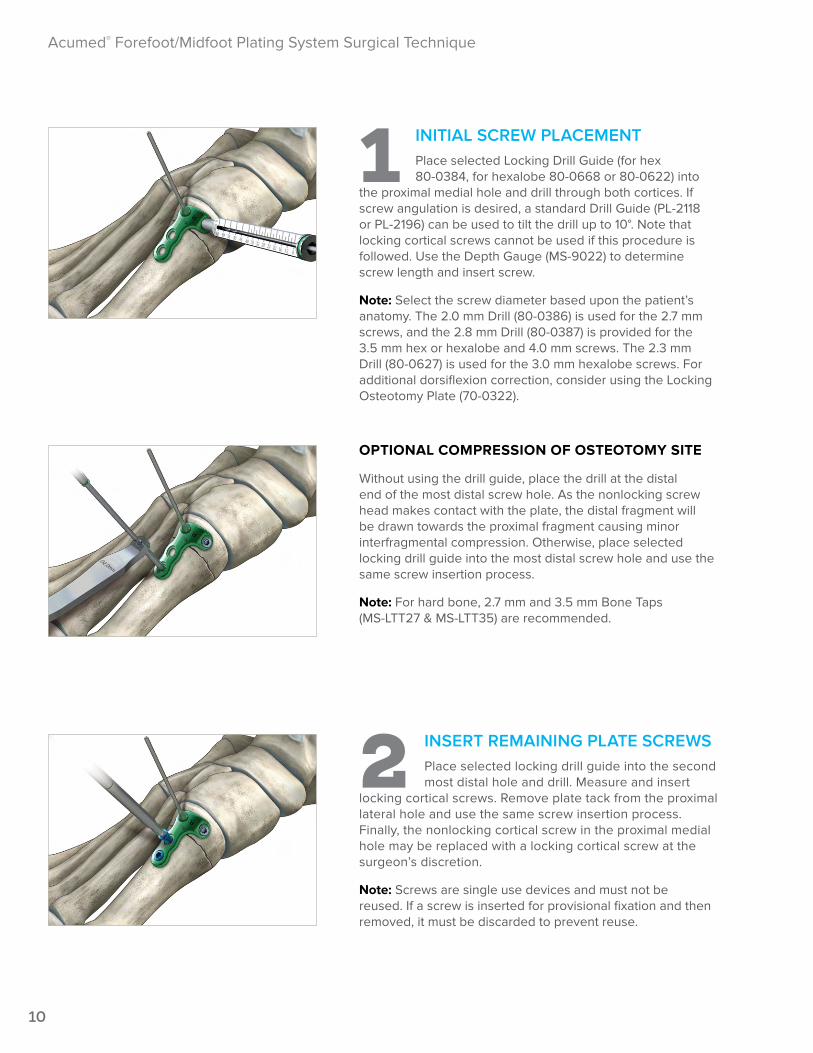
1 INITIAL SCREW PLACEMENTPlace selected Locking Drill Guide (for hex 80-0384, for hexalobe 80-0668 or 80-0622) into
the proximal medial hole and drill through both cortices. If screw angulation is desired, a standard Drill Guide (PL-2118 or PL-2196) can be used to tilt the drill up to 10°. Note that locking cortical screws cannot be used if this procedure is followed. Use the Depth Gauge (MS-9022) to determine screw length and insert screw.
Note: Select the screw diameter based upon the patient’s anatomy. The 2.0 mm Drill (80-0386) is used for the 2.7 mm screws, and the 2.8 mm Drill (80-0387) is provided for the 3.5 mm hex or hexalobe and 4.0 mm screws. The 2.3 mm Drill (80-0627) is used for the 3.0 mm hexalobe screws. For additional dorsiflexion correction, consider using the Locking Osteotomy Plate (70-0322).
OPTIONAL COMPRESSION OF OSTEOTOMY SITE
Without using the drill guide, place the drill at the distal end of the most distal screw hole. As the nonlocking screw head makes contact with the plate, the distal fragment will be drawn towards the proximal fragment causing minor interfragmental compression. Otherwise, place selected locking drill guide into the most distal screw hole and use the same screw insertion process.
Note: For hard bone, 2.7 mm and 3.5 mm Bone Taps (MS-LTT27 & MS-LTT35) are recommended.
2 INSERT REMAINING PLATE SCREWSPlace selected locking drill guide into the second most distal hole and drill. Measure and insert
locking cortical screws. Remove plate tack from the proximal lateral hole and use the same screw insertion process. Finally, the nonlocking cortical screw in the proximal medial hole may be replaced with a locking cortical screw at the surgeon’s discretion.
Note: Screws are single use devices and must not be reused. If a screw is inserted for provisional fixation and then removed, it must be discarded to prevent reuse.
11
Acumed® Forefoot/Midfoot Plating System Surgical Technique
3 POSTOPERATIVE PROTOCOLThe foot is protected with a post-op shoe and dressing. The patient is allowed to proceed with
weight-bearing activities as determined by surgeon.

12
Acumed® Forefoot/Midfoot Plating System Surgical Technique
Locking TMT Plate Arthrodesis Procedure Surgical TechniqueDouglas N. Beaman, M.D.
1 EXPOSUREThe first TMT joint is exposed through a medial incision. Carry dissection down to expose the
anterior tibialis tendon, which is protected. A portion of the tendon may need to be elevated from the medial cuneiform and metatarsal; however, this should be minimized. The joint is exposed medially then dorsally and plantarly, carefully avoiding the extensor hallux longus tendon at the dorsal aspect of the joint.
Note: Image intensification is recommended during this procedure to confirm reduction and placement of hardware.
2 TMT JOINT PREPARATIONGain access to the first TMT joint and perform joint preparation in the standard fashion with
thorough removal of all articular cartilage and preparation of subchondral bone. Confirm the correct positioning of the metatarsal and cuneiform, and provisionally fix the joints involved with K-wires placed superiorly and inferiorly to allow for the plate.
Note: If interfragmentary lag screw fixation is desired to supplement the plate, it should be placed first, and typically oriented from the plantar aspect of the metatarsal base proximally into the medial cuneiform, as the plate sits dorso-medially. Lag screw fixation may also occur through the plate’s slot.
3 PLATE PLACEMENT AND POSITIONINGApply the plate to the dorsal medial aspect of the
TMT joint and secure with a Plate Tack (PL-PTACK) or .062" K-wire (WS-1607ST) through the distal K-wire hole.
Note: The TMT plates are precontoured to match the anatomy. If bending is required to match specific patient anatomy or other factors, use the plate benders provided (PL-2040 & PL-2045) and bend in one direction only. DO NOT BEND IN BOTH DIRECTIONS.

13
Acumed® Forefoot/Midfoot Plating System Surgical Technique
4 INITIAL SCREW PLACEMENTInsert screw—the initial screw should be nonlocking and is typically placed in the distal
cuneiform hole as shown. According to the surgeon’s preference, the screw can be placed across one, two or all three cuneiforms for stability. Use the Depth Gauge (MS-9022) to determine screw length. Choose the appropriate size screw and insert into the bone.
Note: Select the screw diameter based upon the patient’s bone size. The 2.0 mm Drill (80-0386) is used for the 2.7 mm screws, and the 2.8 mm Drill (80-0387) is provided for the 3.5 mm hex or hexalobe and 4.0 mm screws. If a lag screw is used through the plate, it should be placed first and placed through the oval metatarsal hole.
5 COMPRESS FUSION SITEPlace the gold end of the Offset Drill Guide (PL-2095) into the plate’s compression slot with
the arrow on the guide pointing toward the fusion site. Drill and measure for screw length. Insert appropriate size nonlocking screw to apply 1 mm of compression to the fusion site.
6 INSERT REMAINING SCREWSRemove the plate tack from the distal K-wire hole. Place selected locking drill guide into the distal
metatarsal hole and drill if locking screw is desired. Measure and insert locking cortical screws. Follow the same process for the proximal cuneiform hole. Following irrigation, close the wound.
Note: For additional fixation, a longer cortical screw may be used to cross into the other cuneiforms. This may also stabilize inter-cuneiform fusions
14
Acumed® Forefoot/Midfoot Plating System Surgical Technique
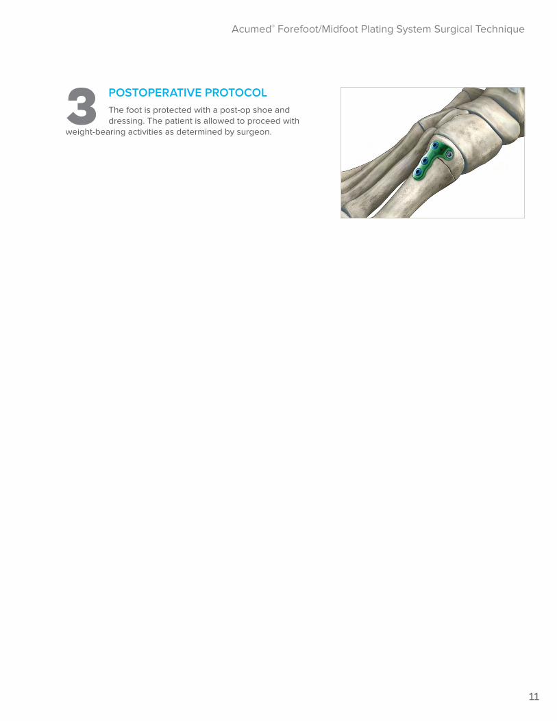
7 POSTOPERATIVE PROTOCOLThe foot is protected with a post-op shoe and dressing. The patient is allowed to proceed with
weight-bearing activities as determined by surgeon.

15
Acumed® Forefoot/Midfoot Plating System Surgical Technique
Locking TMT Plate Trauma Procedure Surgical TechniqueDouglas N. Beaman, M.D.
1 EXPOSUREThe first TMT joint is exposed through a medial incision. Carry dissection down to expose the
anterior tibialis tendon, which is protected. A portion of the tendon may need to be elevated from the medial cuneiform and metatarsal, however, this should be minimized. The joint is exposed medially then dorsally and plantarly, carefully avoiding the extensor hallux longus tendon at the dorsal aspect of the joint.
Note: Image intensification is recommended during this procedure to confirm reduction and placement of hardware.
2 TMT JOINT PREPARATIONReduce joint by aligning anatomic landmarks and fix provisionally with .045" K-wires (WS-1106ST)
placed superiorly and inferiorly across the joint to allow room for the plate.
Note: Definitive fracture stabilization of intra-articular fragments can be performed with intrafragmentary screw fixation.
3 PLATE PLACEMENT AND POSITIONINGApply the plate to the dorsal medial aspect of the
TMT joint, and secure with a Plate Tack (PL-PTACK) or .062" K-wire through the distal K-wire hole.
Note: The TMT plates are precontoured to match the anatomy. If bending is required to match specific patient anatomy or other factors, use the plate benders provided (PL-2040 & PL-2045) and bend in one direction only. DO NOT BEND IN BOTH DIRECTIONS.
16
Acumed® Forefoot/Midfoot Plating System Surgical Technique
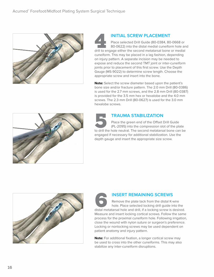
4 INITIAL SCREW PLACEMENTPlace selected Drill Guide (80-0384, 80-0668 or 80-0622) into the distal medial cuneiform hole and
drill to engage either the second metatarsal bone or medial cuneiform. This may be placed in a lag fashion, depending on injury pattern. A separate incision may be needed to expose and reduce the second TMT joint or inter-cuneiform joints prior to placement of this first screw. Use the Depth Gauge (MS-9022) to determine screw length. Choose the appropriate screw and insert into the bone.
Note: Select the screw diameter based upon the patient’s bone size and/or fracture pattern. The 2.0 mm Drill (80-0386) is used for the 2.7 mm screws, and the 2.8 mm Drill (80-0387) is provided for the 3.5 mm hex or hexalobe and the 4.0 mm screws. The 2.3 mm Drill (80-0627) is used for the 3.0 mm hexalobe screws.
5 TRAUMA STABILIZATIONPlace the green end of the Offset Drill Guide (PL-2095) into the compression slot of the plate
to drill the hole neutral. The second metatarsal bone can be engaged if necessary for additional stabilization. Use the depth gauge and insert the appropriate size screw.
6 INSERT REMAINING SCREWSRemove the plate tack from the distal K-wire hole. Place selected locking drill guide into the
distal metatarsal hole and drill, if a locking screw is desired. Measure and insert locking cortical screws. Follow the same process for the proximal cuneiform hole. Following irrigation, close the wound with nylon suture or surgeon’s preference. Locking or nonlocking screws may be used dependent on patient anatomy and injury pattern.
Note: For additional fixation, a longer cortical screw may be used to cross into the other cuneiforms. This may also stabilize any inter-cuneiform disruptions.
17
Acumed® Forefoot/Midfoot Plating System Surgical Technique
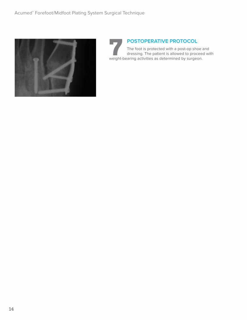
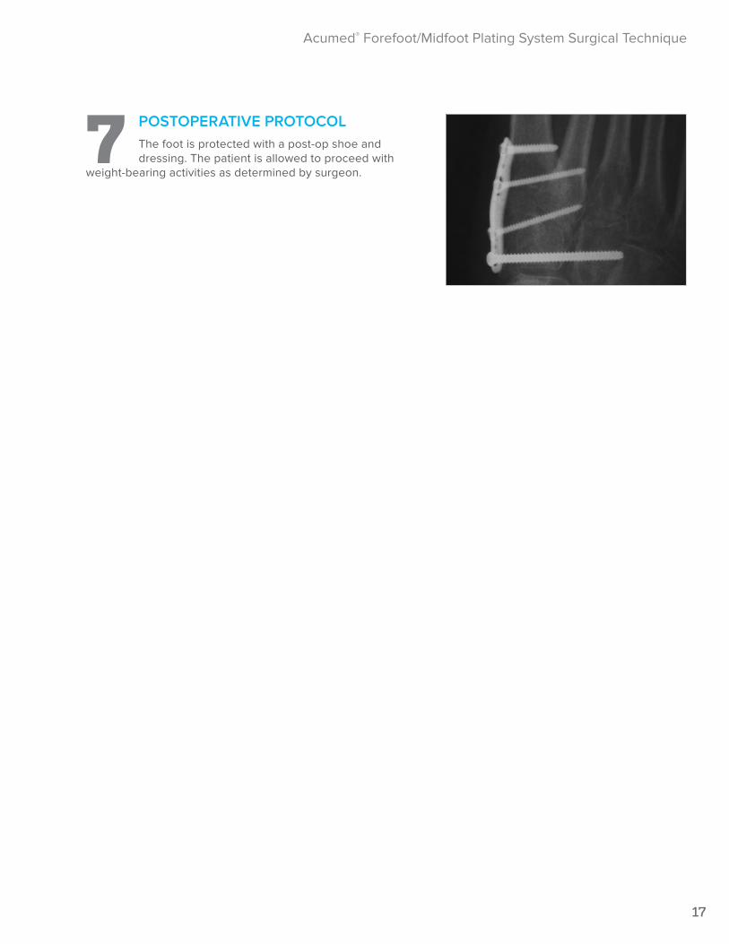
7 POSTOPERATIVE PROTOCOLThe foot is protected with a post-op shoe and dressing. The patient is allowed to proceed with
weight-bearing activities as determined by surgeon.
18
Acumed® Forefoot/Midfoot Plating System Surgical Technique
Locking Extended TMT Plate Trauma Procedure Surgical TechniqueDouglas N. Beaman, M.D.
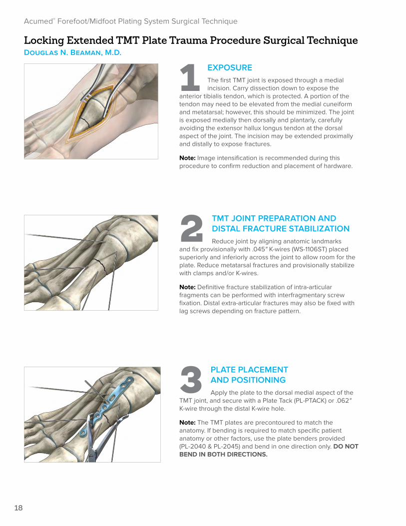
1 EXPOSUREThe first TMT joint is exposed through a medial incision. Carry dissection down to expose the
anterior tibialis tendon, which is protected. A portion of the tendon may need to be elevated from the medial cuneiform and metatarsal; however, this should be minimized. The joint is exposed medially then dorsally and plantarly, carefully avoiding the extensor hallux longus tendon at the dorsal aspect of the joint. The incision may be extended proximally and distally to expose fractures.
Note: Image intensification is recommended during this procedure to confirm reduction and placement of hardware.
2 TMT JOINT PREPARATION AND DISTAL FRACTURE STABILIZATIONReduce joint by aligning anatomic landmarks
and fix provisionally with .045" K-wires (WS-1106ST) placed superiorly and inferiorly across the joint to allow room for the plate. Reduce metatarsal fractures and provisionally stabilize with clamps and/or K-wires.
Note: Definitive fracture stabilization of intra-articular fragments can be performed with interfragmentary screw fixation. Distal extra-articular fractures may also be fixed with lag screws depending on fracture pattern.
3 PLATE PLACEMENT AND POSITIONINGApply the plate to the dorsal medial aspect of the
TMT joint, and secure with a Plate Tack (PL-PTACK) or .062" K-wire through the distal K-wire hole.
Note: The TMT plates are precontoured to match the anatomy. If bending is required to match specific patient anatomy or other factors, use the plate benders provided (PL-2040 & PL-2045) and bend in one direction only. DO NOT BEND IN BOTH DIRECTIONS.
19
Acumed® Forefoot/Midfoot Plating System Surgical Technique
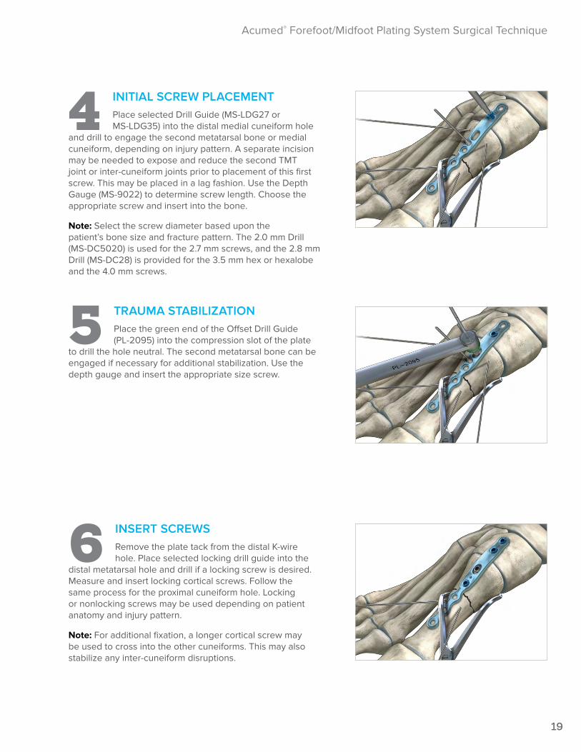
4 INITIAL SCREW PLACEMENTPlace selected Drill Guide (MS-LDG27 or MS-LDG35) into the distal medial cuneiform hole
and drill to engage the second metatarsal bone or medial cuneiform, depending on injury pattern. A separate incision may be needed to expose and reduce the second TMT joint or inter-cuneiform joints prior to placement of this first screw. This may be placed in a lag fashion. Use the Depth Gauge (MS-9022) to determine screw length. Choose the appropriate screw and insert into the bone.
Note: Select the screw diameter based upon the patient’s bone size and fracture pattern. The 2.0 mm Drill (MS-DC5020) is used for the 2.7 mm screws, and the 2.8 mm Drill (MS-DC28) is provided for the 3.5 mm hex or hexalobe and the 4.0 mm screws.
5 TRAUMA STABILIZATIONPlace the green end of the Offset Drill Guide (PL-2095) into the compression slot of the plate
to drill the hole neutral. The second metatarsal bone can be engaged if necessary for additional stabilization. Use the depth gauge and insert the appropriate size screw.
6 INSERT SCREWSRemove the plate tack from the distal K-wire hole. Place selected locking drill guide into the
distal metatarsal hole and drill if a locking screw is desired. Measure and insert locking cortical screws. Follow the same process for the proximal cuneiform hole. Locking or nonlocking screws may be used depending on patient anatomy and injury pattern.
Note: For additional fixation, a longer cortical screw may be used to cross into the other cuneiforms. This may also stabilize any inter-cuneiform disruptions.
20
Acumed® Forefoot/Midfoot Plating System Surgical Technique
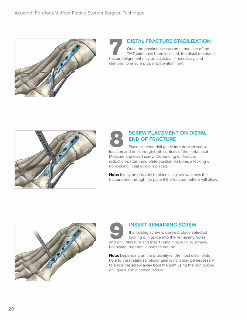
7 DISTAL FRACTURE STABILIZATION Once the proximal screws on either side of the TMT joint have been installed, the distal metatarsal
fracture alignment may be adjusted, if necessary, and clamped to ensure proper plate alignment.
8 SCREW PLACEMENT ON DISTAL END OF FRACTUREPlace selected drill guide into desired screw
location and drill through both cortices of the metatarsal. Measure and insert screw. Depending on fracture reduction/pattern and plate position on bone, a locking or nonlocking initial screw is placed.
Note: It may be possible to place a lag screw across the fracture and through the plate if the fracture pattern will allow.
9 INSERT REMAINING SCREWIf a locking screw is desired, place selected locking drill guide into the remaining holes
and drill. Measure and insert remaining locking screws. Following irrigation, close the wound.
Note: Depending on the proximity of the most distal plate hole to the metatarsal phalangeal joint, it may be necessary to angle the screw away from the joint using the nonlocking drill guide and a cortical screw.
21
Acumed® Forefoot/Midfoot Plating System Surgical Technique
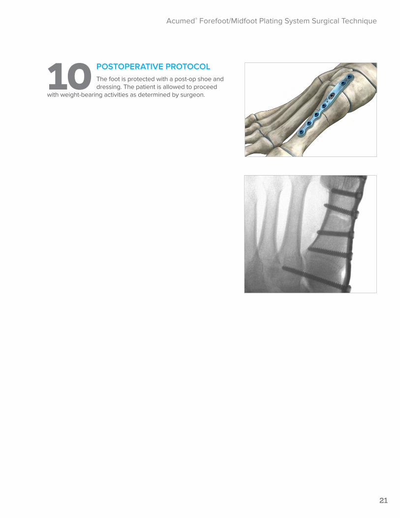
10 POSTOPERATIVE PROTOCOLThe foot is protected with a post-op shoe and dressing. The patient is allowed to proceed
with weight-bearing activities as determined by surgeon.

InstrumentationLower Extremity Modular System
The Lower Extremity Modular System offers instrumentation for foot and ankle surgery. This system includes a screw caddy, locking drill guides, and an array of foot and ankle instrumentation intended to make the system easy to use.
4° Locking MTP Plates 9° Locking MTP Plates
Reamers with Quick Release
Osteotomy Plates with
Compression Slot
Osteotomy Plates
TMT Plates
Ordering Information
23
Ordering Information
23
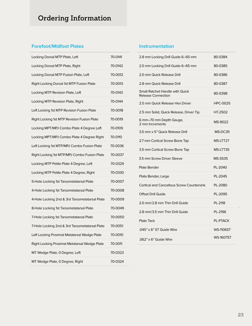
Forefoot/Midfoot Plates
Locking Dorsal MTP Plate, Left 70-0141
Locking Dorsal MTP Plate, Right 70-0142
Locking Dorsal MTP Fusion Plate, Left 70-0012
Right Locking Dorsal 1st MTP Fusion Plate 70-0013
Locking MTP Revision Plate, Left 70-0143
Locking MTP Revision Plate, Right 70-0144
Left Locking 1st MTP Revision Fusion Plate 70-0018
Right Locking 1st MTP Revision Fusion Plate 70-0019
Locking MPT/MPJ Combo Plate 4 Degree Left 70-0109
Locking MPT/MPJ Combo Plate 4 Degree Right 70-0110
Left Locking 1st MTP/MPJ Combo Fusion Plate 70-0036
Right Locking 1st MTP/MPJ Combo Fusion Plate 70-0037
Locking MTP Petite Plate 4 Degree, Left 70-0329
Locking MTP Petite Plate 4 Degree, Right 70-0330
5-Hole Locking 1st Tarsometatarsal Plate 70-0007
4-Hole Locking 1st Tarsometatarsal Plate 70-0008
4-Hole Locking 2nd & 3rd Tarsometatarsal Plate 70-0009
8-Hole Locking 1st Tarsometatarsal Plate 70-0049
7-Hole Locking 1st Tarsometatarsal Plate 70-0050
7-Hole Locking 2nd & 3rd Tarsometatarsal Plate 70-0051
Left Locking Proximal Metatarsal Wedge Plate 70-0010
Right Locking Proximal Metatarsal Wedge Plate 70-0011
MT Wedge Plate, 0 Degree, Left 70-0323
MT Wedge Plate, 0 Degree, Right 70-0324
Instrumentation
2.8 mm Locking Drill Guide 6–65 mm 80-0384
2.0 mm Locking Drill Guide 6–65 mm 80-0385
2.0 mm Quick Release Drill 80-0386
2.8 mm Quick Release Drill 80-0387
Small Ratchet Handle with Quick Release Connection 80-0398
2.5 mm Quick Release Hex Driver HPC-0025
2.5 mm Solid, Quick Release, Driver Tip HT-2502
6 mm–70 mm Depth Gauge, 2 mm Increments MS-9022
3.5 mm x 5" Quick Release Drill MS-DC35
2.7 mm Cortical Screw Bone Tap MS-LTT27
3.5 mm Cortical Screw Bone Tap MS-LTT35
3.5 mm Screw Driver Sleeve MS-SS35
Plate Bender PL-2040
Plate Bender, Large PL-2045
Cortical and Cancellous Screw Countersink PL-2080
Offset Drill Guide PL-2095
2.0 mm/2.8 mm Thin Drill Guide PL-2118
2.8 mm/3.5 mm Thin Drill Guide PL-2196
Plate Tack PL-PTACK
.045" x 6" ST Guide Wire WS-1106ST
.062" x 6" Guide Wire WS-1607ST

Ordering Information
24
Soft Tissue Instrument Tray
8" Bone Reduction Forceps MS-1280
Bone Reduction Forceps, 5.25" MS-45300
Periosteal Elevator, 7.25" MS-46211
15 mm Hohmann Retractor MS-46827
Bone Reduction Forceps with Points, 5 Broad MS-47135
Inge Retractor, 6.5" MS-48217
Needle Nose Pliers, 5.5" MS-48245
Freer Elevator, 7.5" MS-57614
Small Pointed Reduction Forceps OW-1200
Reduction Forceps with Serrated Jaw PL-CL04
8 mm Hohmann Retractor PL-CL05
Sharp Hook PL-CL06
Tray Components
Forefoot/Midfoot System Tray Assembly 80-0589
Forefoot/Midfoot System Tray Base 80-0590
Lower Extremity Tray Lid 80-0431
Lower Extremity Modular System Screw Caddy
80-0430
Reamers
16 mm MTP Reamer Concave 80-0569
16 mm MTP Reamer Convex 80-0570
18 mm MTP Reamer Concave 80-0571
18 mm MTP Reamer Convex 80-0572
20 mm MTP Reamer Concave 80-0573
20 mm MTP Reamer Convex 80-0574
22 mm MTP Reamer Concave 80-0575
22 mm MTP Reamer Convex 80-0576
Optional Instruments
Inge Retractor without Teeth 80-0472
Large Cannulated Quick Release Driver Handle MS-3200
Plate Holder Assembly PL-2030
Hexalobe Instruments
2.8 mm Hexalobe Lkg Drill Guide 6–65 mm 80-0668
2.3 mm Hexalobe Lkg Drill Guide 6–65 mm 80-0622
2.3 mm Quick Release Drill 80-0627
3.0 mm x 5" Quick Release Drill 80-1088
T15 Stick Fit Hexalobe Driver 80-0760
T15 6" Long Stick Fit Hexalobe Driver 80-1065
Depth Gauge 6–65 mm 80-0623

25
3.0 mm Nonlocking Hexalobe Screws
3.0 mm x 8 mm Nonlocking Hexalobe Screw 30-0301
3.0 mm x 10 mm Nonlocking Hexalobe Screw 30-0302
3.0 mm x 12 mm Nonlocking Hexalobe Screw 30-0303
3.0 mm x 14 mm Nonlocking Hexalobe Screw 30-0304
3.0 mm x 16 mm Nonlocking Hexalobe Screw 30-0305
3.0 mm x 18 mm Nonlocking Hexalobe Screw 30-0306
3.0 mm x 20 mm Nonlocking Hexalobe Screw 30-0307
3.0 mm x 22 mm Nonlocking Hexalobe Screw 30-0308
3.0 mm x 24 mm Nonlocking Hexalobe Screw 30-0309
3.0 mm x 26 mm Nonlocking Hexalobe Screw 30-0310
3.0 mm x 28 mm Nonlocking Hexalobe Screw 30-0311
3.0 mm x 30 mm Nonlocking Hexalobe Screw 30-0312
3.0 mm x 32 mm Nonlocking Hexalobe Screw 30-0313
3.0 mm x 34 mm Nonlocking Hexalobe Screw 30-0314
3.0 mm x 36 mm Nonlocking Hexalobe Screw 30-0315
3.0 mm x 38 mm Nonlocking Hexalobe Screw 30-0316
3.0 mm x 40 mm Nonlocking Hexalobe Screw 30-0317
3.0 mm x 45 mm Nonlocking Hexalobe Screw 30-0318
3.0 mm x 50 mm Nonlocking Hexalobe Screw 30-0319
3.0 mm x 55 mm Non-Locking Hexalobe Screw 30-0320
3.5 mm Nonlocking Hexalobe Screws
3.5 mm x 8 mm Nonlocking Hexalobe Screw 30-0255
3.5 mm x 10 mm Nonlocking Hexalobe Screw 30-0256
3.5 mm x 12 mm Nonlocking Hexalobe Screw 30-0257
3.5 mm x 14 mm Nonlocking Hexalobe Screw 30-0258
3.5 mm x 16 mm Nonlocking Hexalobe Screw 30-0259
3.5 mm x 18 mm Nonlocking Hexalobe Screw 30-0260
3.5 mm x 20 mm Nonlocking Hexalobe Screw 30-0261
3.5 mm x 22 mm Nonlocking Hexalobe Screw 30-0262
3.5 mm x 24 mm Nonlocking Hexalobe Screw 30-0263
3.5 mm x 26 mm Nonlocking Hexalobe Screw 30-0264
3.5 mm x 28 mm Nonlocking Hexalobe Screw 30-0265
3.5 mm x 30 mm Nonlocking Hexalobe Screw 30-0266
3.5 mm x 32 mm Nonlocking Hexalobe Screw 30-0267
3.5 mm x 34 mm Nonlocking Hexalobe Screw 30-0268
3.5 mm x 36 mm Nonlocking Hexalobe Screw 30-0269
3.5 mm x 38 mm Nonlocking Hexalobe Screw 30-0270
3.5 mm x 40 mm Nonlocking Hexalobe Screw 30-0271
3.5 mm x 45 mm Nonlocking Hexalobe Screw 30-0272
3.5 mm x 50 mm Nonlocking Hexalobe Screw 30-0273
3.5 mm x 55 mm Nonlocking Hexalobe Screw 30-0274
3.5 mm x 60 mm Nonlocking Hexalobe Screw 30-0275
3.5 mm x 65 mm Nonlocking Hexalobe Screw 30-0276
26
Ordering Information
26
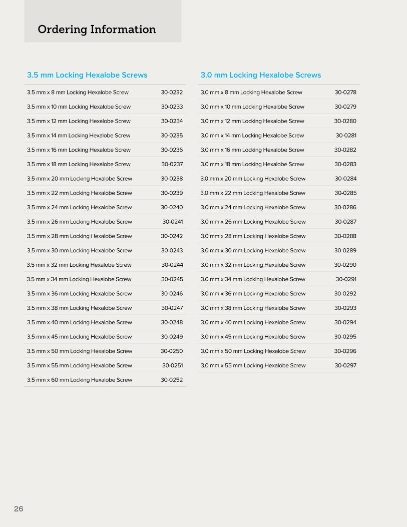
3.5 mm Locking Hexalobe Screws
3.5 mm x 8 mm Locking Hexalobe Screw 30-0232
3.5 mm x 10 mm Locking Hexalobe Screw 30-0233
3.5 mm x 12 mm Locking Hexalobe Screw 30-0234
3.5 mm x 14 mm Locking Hexalobe Screw 30-0235
3.5 mm x 16 mm Locking Hexalobe Screw 30-0236
3.5 mm x 18 mm Locking Hexalobe Screw 30-0237
3.5 mm x 20 mm Locking Hexalobe Screw 30-0238
3.5 mm x 22 mm Locking Hexalobe Screw 30-0239
3.5 mm x 24 mm Locking Hexalobe Screw 30-0240
3.5 mm x 26 mm Locking Hexalobe Screw 30-0241
3.5 mm x 28 mm Locking Hexalobe Screw 30-0242
3.5 mm x 30 mm Locking Hexalobe Screw 30-0243
3.5 mm x 32 mm Locking Hexalobe Screw 30-0244
3.5 mm x 34 mm Locking Hexalobe Screw 30-0245
3.5 mm x 36 mm Locking Hexalobe Screw 30-0246
3.5 mm x 38 mm Locking Hexalobe Screw 30-0247
3.5 mm x 40 mm Locking Hexalobe Screw 30-0248
3.5 mm x 45 mm Locking Hexalobe Screw 30-0249
3.5 mm x 50 mm Locking Hexalobe Screw 30-0250
3.5 mm x 55 mm Locking Hexalobe Screw 30-0251
3.5 mm x 60 mm Locking Hexalobe Screw 30-0252
3.0 mm Locking Hexalobe Screws
3.0 mm x 8 mm Locking Hexalobe Screw 30-0278
3.0 mm x 10 mm Locking Hexalobe Screw 30-0279
3.0 mm x 12 mm Locking Hexalobe Screw 30-0280
3.0 mm x 14 mm Locking Hexalobe Screw 30-0281
3.0 mm x 16 mm Locking Hexalobe Screw 30-0282
3.0 mm x 18 mm Locking Hexalobe Screw 30-0283
3.0 mm x 20 mm Locking Hexalobe Screw 30-0284
3.0 mm x 22 mm Locking Hexalobe Screw 30-0285
3.0 mm x 24 mm Locking Hexalobe Screw 30-0286
3.0 mm x 26 mm Locking Hexalobe Screw 30-0287
3.0 mm x 28 mm Locking Hexalobe Screw 30-0288
3.0 mm x 30 mm Locking Hexalobe Screw 30-0289
3.0 mm x 32 mm Locking Hexalobe Screw 30-0290
3.0 mm x 34 mm Locking Hexalobe Screw 30-0291
3.0 mm x 36 mm Locking Hexalobe Screw 30-0292
3.0 mm x 38 mm Locking Hexalobe Screw 30-0293
3.0 mm x 40 mm Locking Hexalobe Screw 30-0294
3.0 mm x 45 mm Locking Hexalobe Screw 30-0295
3.0 mm x 50 mm Locking Hexalobe Screw 30-0296
3.0 mm x 55 mm Locking Hexalobe Screw 30-0297

27
Notes:

These materials contain information about products that may or may not be available in any particular country or may be available under different trademarks in different countries. The products may be approved or cleared by governmental regulatory organizations for sale or use with different indications or restrictions in different countries. Products may not be approved for use in all countries. Nothing contained on these materials should be construed as a promotion or solicitation for any product or for the use of any product in a particular way which is not authorized under the laws and regulations of the country where the reader is located. Specific questions physicians may have about the availability and use of the products described on these materials should be directed to their particular local sales representative. Specific questions patients may have about the use of the products described in these materials or the appropriateness for their own conditions should be directed to their own physician.
LEX00-03-CEffective: 02/2016
© 2016 Acumed® LLC
Acumed®5885 NW Cornelius Pass RoadHillsboro, OR 97124
Office: 888.627.9957 Fax: 503.520.9618 acumed.net