sv40 bi - ptb-sales.com · 1.4lubricants the sogevac® sv40 bi pump should be run with a synthetic...
TRANSCRIPT

SOGEVAC® SV40 BISingle-stage, oil-sealed rotary vane pump
Operating instructions 300270034_002_C0
Waters Corporation
Ref.:960331V3007

2 300270034_002_C0 - 11/2016 - © Leybold
Contents
Page
Important Safety Information 3
1 Description 5
1.1 Principle of operation 5
1.2 Technical characteristics 6
1.3 Accessories 8
1.4 Lubricants 8
2 Transport and Storing 9
2.1 Transport and packaging 9
2.2 Mounting orientation 9
2.3 Storing 9
3 Installation 10
3.1 Setting up 10
3.2 Electrical connections 11
4 Operation 13
4.1 Operation 13
4.2 Working in cycles in / out 14
4.3 Switching off / Shutdown 14
5 Maintenance 15
5.1 Safety Information 15
5.2 Maintenance Intervals 15
5.3 Leybold Service 16
5.4 Maintenance Work 16
6 Troubleshooting 18
7 Spare parts 20
EU Declaration of Conformity 24
3300270034_002_C0 - 11/2016 - © Leybold
Important Safety Information
Indicates procedures that must be strictly observed to prevent hazards to persons.
Indicates procedures that must be strictly observed to prevent damage to, or destruction of the product.
Emphasizes additional application information and other useful information provided within these Operating Instructions.
The Leybold Sogevac® SV40 BI has been designed for safe and efficient operation when used properly and in accordance with these Operating Instructions. It is the responsibility of the user to carefully read and strictly observe all safety precautions described in this section and throughout the Operating Instructions. The Sogevac® SV40 BI must only be operated indoor in the proper condition and under the conditions described in the Operating Instructions. If not, the protection provided by the equipment may be impaired. It must be operated and maintained by trained personnel only. Consult local, state, and national agencies regarding specific requirements and regulations. Address any further safety, operation and/or maintenance questions to our nearest office.
Failure to observe the following precautions could result in serious personal injury!
Sogevac® pumps are not designed:
■ for pumping of dusty, aggressive, corrosive, flammable or explosive gases or gases mixtures,
■ for pumping of oxygen or other highly reactive gases with a greater concentration than atmospheric concentration (>20%),
■ for working in flammable, explosive or dusty environment.
For all these cases, special materials must be used. In case of doubt, please contact Leybold.
See also the limits of use indicated in the CE declaration of conformity.
Never expose part of the body to the vacuum. There is a danger of injury. Never operate the pump with an open and thus accessible inlet. Vacuum connections as well as oil filling and oil draining openings must not be open during operation of the pump.
When operating pump is hot and some surfaces could reach a temperature higher than 80 °C (176 °F). There is a risk of burn by touching.
Depending on the process involved, dangerous substances and oil may escape from the pump. Take the necessary safety precautions !
Disconnect the unit from the power supply before starting any work.
Pump must not be operated above 2000 m sea level.
These installation and operating instructions are valid for Waters use of the
Safety Information
Warning
Caution
Note
Warning
Warning
4 300270034_002_C0 - 11/2016 - © Leybold
Sogevac® pumps, model SV40 BI. The Sogevac® vacuum pumps have been manufactured according to the latest technical standards and safety regulations. If not installed properly or not used as directed, dangerous situations or damages could occur.
It is mandatory that these operating instructions be read and understood prior to vacuum pump installation and start-up.
The pump complies to the standard EN 61010-1-2004.
Take appropriate precautions to insure that the pump cannot start.
If the pump has pumped hazardous gases it will be absolutely necessary to determine the nature of the hazard involved and take the appropriate safety precautions.
Observe all safety regulations!
Take adequate safety precautions prior to opening the intake or exhaust port.
Failure to observe the following precautions could result in damage to the equipment!
Liquid and solid particles must not enter the pump. Install the adequate filters, separators and/or condensers. In case of doubt consult Leybold.
The intake line of the pump must never be connected to a device with over atmospheric pressure. Design the exhaust line so that no pressure higher than 1,15 bar abs. (0,15 bar rel.) can occur.
Operating of the pump without oil or operating with incorrect direction of rotation can destroy the pump.
Never use discarded seals. Always assemble using new seals.
Respect the instructions concerning environment protection when discarding used oil or exhaust filters!
The pump must be packaged in such a way that it will not be damaged during shipping, and so that no harmful substances can escape from the package.
We reserve the right to alter the design or any data given in these Operating Instructions. The illustrations are not binding.
Caution : hot surface ! In normal operation, the pump surface temperature can exceed 80°C. There is a risk of burning. Switch off the pump and let it cool down before any intervention or take appropriate precautions.
Caution
Note
Safety Information
Warning
Warning
Caution

5300270034_002_C0 - 11/2016 - © Leybold
1 DescriptionSogevac® pumps are designed for pumping of inert gases in the range of rough vacuum, between atmospheric pressure and ultimate pressure of the pump.
When removing condensable vapors, periodic opening of the gas ballast valve is required.
1.1 Principle of operationThe Sogevac® pumps SV40 BI are single-stage oil-sealed rotary vane vacuum pumps.
The rotor, having three slots in which the vanes are sliding, is eccentrically installed in a pump cylinder (stator).
The vanes separate the interior space into 3 chambers. The volume of these chambers varies with the rotation of the rotor.
The gas sucked into the inlet chamber is compressed and then pushed out at the exhaust valve.
The oil injected in the inlet chamber guarantees the air-tightness, the lubrication and cooling of the pump. It is dragged off by the compressed gases and roughly separated by gravity when entering in the oil sump. A fine separation is then operated in the exhaust filter. An internal transfer pushes the collected oil back into the vacuum generator, the transfer is operated by a float valve to avoid atmospheric air coming from the oil casing to the inlet of the pump when no oil is present in the recovery system.
The oil circulation functions by differential pressures.
The pumps are equipped with a gas ballast valve for pumping condensable vapors.
The anti suckback valve at the inlet flange avoids oil coming back into the inlet line when the pump is stopped. This is valid for working pressures below 100 mbar and under the condition that the valve is kept clean and in good condition. The anti suck
back valve is not a safety valve. If oil back flowing is to be avoided by all means, it is necessary to mount a separate safety valve on the pump inlet.
Description

6 300270034_002_C0 - 11/2016 - © Leybold
1.2 Technical characteristics
SV40 B
Technical data 50 Hz 60 Hz
Nominal pumping speed m3/h 42 50
Pumping speed (according to PNEUROP) m3/h at 2 mbar > 35 > 45
Ultimate partial pressure without gas ballast mbar ≤ 0,25 ≤ 0,25
Ultimate total pressure with small gas ballast mbar ≤ 0,8 ≤ 0,8
Water vapor tolerance: ■ with small gas ballast mbar 10 10
Water vapor tolerable load: ■ with small gas ballast kg.h-1 0,28 0,34
Noise level (according to DIN 46 635) dB (A) 60 (1φ) 63 (1φ) Motor power - Rated rotational speed kW - min-1 1,6-1500 1,9-1800 (1φ) (1φ) Mains voltage (+/- 10 %) AC ~ V 200 240
Protection - Insulation IP 55 - F IP 55 - F
Leak rate mbar.I.s-1 <1 x 10⁻³ <1 x 10⁻³
Oil type / Capacity l LV0110 / 2x1
Intake connection 25KF
Exhaust connection Barbed fitting 0.5" ID tubing
See pump nameplate for further data.
Description

7300270034_002_C0 - 11/2016 - © Leybold
Description
Pumping speeds curves SV40 B - SV65 B
fig. 1
SV40 BI
Pumping speeds curves SV40 BI
Pum
ping
spe
ed
Pum
ping
spe
ed

8 300270034_002_C0 - 11/2016 - © Leybold
Description
1.3 Accessories
SV40 BI
Specification Cat. Nr.
Oil level switch 711 19 110
Temperature switch 9 714 32 820
Exhaust filter over 9 714 25 890 pressure switch
Exhaust filter over 951 94 pressure manometer
Oil drain tap 711 30 114
1.4 LubricantsThe Sogevac® SV40 BI pump should be run with a synthetic oil for vacuum pumps with low viscosity according to ISO category VG32. The Leybold oil LV0110 corresponds to these prescriptions.
LV0110 oil: Conditioning Reference
1 l 9 714 50 502
Use only oil LV0110.

9300270034_002_C0 - 11/2016 - © Leybold
Transport and storing
2 Transport and Storing
2.1 Transport and packagingSogevac® vacuum pumps pass a rigorous operating test in our factory and are packaged to avoid transport damages.
Please check packaging on delivery for transport damages.
The outer package bears a shock indicator, turning red at 50 g. Should the shock indicator have reacted, a transportation damage may have occurred and the freight forwarder must be advised.
Packing materials should be disposed off according to environmental laws or re-cycled. These operating instructions are part of the consignment.
The connection ports are blanked off by plastic protective caps or self-adhesives. Take these caps or self-adhesives away before turning on the pump.
The necessary oil is supplied in cans beside the pump.
2.2 Mounting orientationSee required space on drawings in paragraph 1.2.
Pumps which have been filled with oil must only be moved in the upright position (horizontally). Otherwise oil may escape. The angle of slope may not be over 10° max. Avoid any other orientations while moving the pump.
Only use the lifting lugs which are provided on the pump to lift the pump with the specified lifting devices.
Make sure that these have been installed safety. Use suitable lifting equipment. Make sure that all safety regulations are observed.
2.3 StoringBefore stocking the pump for a long time put it back in its original condition (blank off inlet and exhaust ports with the shipping seals, drain the oil) and store the pump in a dry place at room temperature.
Storage temperature: - 15°C to + 50°C.
Until the pump is put back in to service again, the pump should be stored in a dry place, preferably at room temperature (20 °C - 168 °F). Before taking the pump out of service, it should be properly disconnected from the vacuum system, purged with dry nitrogen and the oil should be exchanged too. The gas ballast must be closed and if the pump is to be shelved for a longer period of time it should be sealed in a plastic bag together with a desiccant (Silicagel).
If the pump has been shelved for over one year, standard maintenance must be done and the oil must be exchanged too before the pump is put in to service once more.
We recommend that you contact the service from Leybold.
Caution

10 300270034_002_C0 - 11/2016 - © Leybold
3 InstallationIt is essential to observe the following instructions step by step to ensure safe start-up. Start-up may only be conducted by trained specialists.
The standard pump is not suitable for installation in explosion hazard ATEX areas. Please contact us, if you are planning such an application. Before installing the pump you must reliably disconnect it from the electrical power supply and prevent the pump form running up inadvertently.
Observe all safety regulations.
3.1 Setting upThe pump must be set up or mounted horizontally on a flat surface. Special mounting is not required.
The pump must be levelled within a tolerance of ± 2 degrees.
The following ambient operating environment must be observed:
■ Pollution degree CSA 2
■ Ambient temperature: 12 °C to 40 °C (54 °F to 104 °F),
■ Ambient pressure = Atmospheric pressure.
■ Rel. humidity ≤ 95 % without condensation
In order to avoid over-heating of the pump, an undisturbed fresh airflow to the pump is necessary.
Additional warning note : consider changes in ambient temperatures that might occur when air conditioning is turned down, such as nights and week-ends.
Inlet connection See safety instructions page 3.
■ The inlet flange can be connected with a vacuum-tight flexible hose and/or pipe.
■ The pipes should cause no stresses on the pump’s flanges. If necessary, compensators must be open.
■ Restriction of the pipes must be avoided in order not to decrease the pumping speed of the pump. The nominal diameter of the pipes has to be at least the same as the diameter of pump’s inlet flange.
■ When removing condensable vapors, a gas ballast valve must be open periodically to avoid solvent build up in the oil.
■ Additional warning note: additional air flow may be needed during ballast, as this increases pump temperature.
■ The inlet pressure must not be above atm. pressure.
See also indications on the CSA pump nameplate.
Warning
Caution
Warning
Installation

11300270034_002_C0 - 11/2016 - © Leybold
The electrical installation may only be conducted by a specialist. Local regulations have to be followed.
Electrical connection work must only be carried out by a qualified electrician in accordance with the applicable safety rules, see IEC 60204-1.
The motor must be protected by magnetic thermo breaker type GV2 ME14 adjustable from 6 to 10 A from Schneider Electric or similar. For an operation at 50 Hz the breaker must be set at 8.5 A. For an operation at 60 Hz the breaker must be set at 10 A.
Therefore, even if the pump is not operating, live voltage is present in the motor connection box !
Voltage and frequency mentioned on the pump nameplate must agree with the supply voltage.
.
Connection to exhaust side ■ No valve or restricting devices should be installed in the exhaust line of the pump. If an exhaust line is installed, it must at least have the same diameter as the exhaust flange. It should be installed in a manner so that no condensate can enter the pump (siphon, slope).
The maximum exhaust pressure must neither exceed 1.15 bar absolute (0.15 bar relative), nor fall under atmosphere pressure minus 15 mbar.
3.2 Electrical connectionsEnsure that incoming power to the pump is off before wiring the motor or altering the wiring.
Installation
Warning
Stecker des Schalterkabels.Connection plug of relay cable.Prise de connexion câble relais.
Leistungschluss am Motorschaltkasten.Power socket on motor connection box.Prise de puissance sur boîtier de connexion moteur.
fig. 2
Warning

12 300270034_002_C0 - 11/2016 - © Leybold
The motor connection box integrates an ON/OFF 24 VDC relay. The pump operation is commanded with a 24 VDC signal lead through a dedicated cable.
The final end product must provide a 24 VDC signal (protected by a 3 A fuse) for the remote control power relay coil. This 24 VDC signal shall be generated by a power supply complying to IEC 61010-1: 2001 (2nd Edition) double or reinforced insulation requirements (equivalent standards requirements like IEC60950-1) are acceptable.
3.3 Oil filling
For SV40 BI, the necessary oil is supplied in cans beside the pump.
To fill in the oil, unscrew the oil fill plug (58) and fill in until the oil level rea-ches the “MAX” mark beside the oil sight glass. Typically the whole 1 l oil can is used
Installation
Caution
13300270034_002_C0 - 11/2016 - © Leybold
Operation
4 Operation
4.1 OperationTo avoid overloading the motor, do not start the pump more than 6 times within one hour. If more than 6 starts per hour are necessary keep the pump running and mount a valve which opens and closes into the intake line.
Take note of warning labels on the pump.
Pumping of non-condensable gasesIf the pump system contains mainly non condensable gases, the pumps should be operated without gas ballast.
If the composition of the gases to be pumped is not known and if condensation in the pump cannot be ruled out, run the pump with gas ballast valve open in accordance with section below.
Pumping of condensable gases and vaporsWith the gas ballast valve open and at operating temperature, the Sogevac® pumps can pump pure water vapor up to the values indicated in the Technical Data.
The gas ballast valve is open by a hand lever. The running noise of the pump is slightly louder if the gas ballast valve is open. Before pumping vapors ensure that the pump has warmed up for approx. 30 min. with closed intake line and with open gas ballast valve.
Don’t open the pump to condensable vapors until it has warmed to operating temperature (approximately); pumping process gas with a cold pump results in vapors condensing in the oil.
For processes with a high proportion of condensable vapors, the intake line should be open only slowly after reaching the operating temperature.
One sign of condensation of vapors in the pump is a rise of the oil level during operation of the pump.
When vapors are pumped, the pump must not be switched off immediately after completion of the process because the condensate dissolved in the pump oil may cause changes or corrosion. To prevent this, the pump must continue to operate with open gas ballast valve and closed intake port until the oil is free of condensate. We recommend operating the pump in this mode for at least 30 min. after completion of the process.
Daily ballasting is recommended when continuously pumping larger volumes of condensable vapors.
In cycle operation, the pump should not be switched off between the cycles but should continue to run with gas ballast valve open and intake port closed (if possible via a valve). Power consumption is minimal when the pump is operating at ultimate pressure.
Once all vapors have been pumped off from a process (e. g. during drying), the gas ballast valve can be closed in order to improve the ultimate pressure.
Note
Caution
Warning
Caution
14 300270034_002_C0 - 11/2016 - © Leybold
4.2 Working in cycles in / outWe recommend strongly to limit starting of the pump to 5 or 6 per hour. If the process need it, we recommend utilization of a pneumatic or electromagnetic valve and to let the pump run continously.
4.3 Switching off / ShutdownThe intake port of the Sogevac® pumps contains an anti-suckback valve which closes the intake port when the pump is switched off, thus maintaining the vacuum in the connected apparatus and preventing oil from being sucked back into the apparatus. The valve’s functioning is not impaired by gas ballast operation.
If the pump has to be shutdown, drain the oil flush out the pump with fresh oil and fill in the required amount of clean oil (see § 5.4). Close the connection ports. Special preservation or flushing oils do not need to be used.
When the pump has been switched off due to over heating, initiated by the motor or its temperature detector, the pump must be cooled down to the ambient temperature, and must only be switched on again manually after having eliminated the cause.
In order to prevent the pump from running up unexpectedly after a mains power failure, the pump must be integrated into the control sytem in such a way that the pump can only be started by a manually operated switch. This applies equally to emergency cut-off switches.
In case of switching processes in connection with a pump which has warmed up under operation conditons, the pump must then not be directly switched on again.
Operation
Caution

15300270034_002_C0 - 11/2016 - © Leybold
Maintenance
5 Maintenance
5.1 Safety InformationObserve all safety regulations.
All work must be done by suitably trained personnel. Maintenance or repairs carried out incorrectly will affect the life and performance of the pump and may cause problems when filling warranty claims.
Never mount used seals; always mount new seals.
5.2 Maintenance IntervalsThe intervals stated in the maintenance schedule are approximate values for normal pump operation. Unfavourable ambient conditions and/or aggressive media may significantly reduce the maintenance intervals.
Maintenance job Frequency Section
Check the oil level Daily A
1st oil change After one year of B operation
Subsequent oil changes After one year of B operation
Exhaust filter replacement Annually C
Gas ballast valve Monthly checking D
Inlet flange sifter Annually E cleaning
Anti-suck back valve checking Annually F
Fan cover cleaning Annually G
Electrical connection Annually checking (only by a specialist) In order to simplify the maintenance work we recommend to combine several jobs.
Warning
Caution

16 300270034_002_C0 - 11/2016 - © Leybold
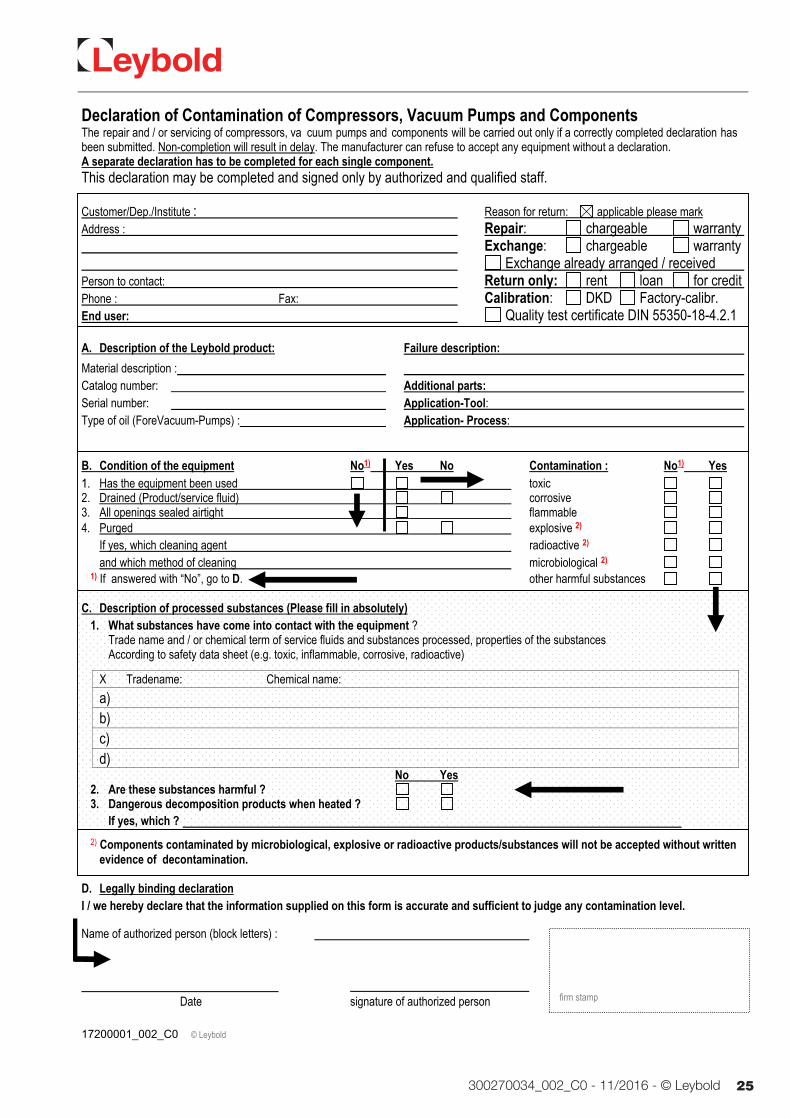
5.3 Leybold ServiceWhenever you send us in equipment, indicate whether the equipment is contaminated or is free of substances which could pose a health hazard.
If it is contaminated, specify exactly which substances are involved. You must use the form we have prepared for this purpose.
A copy of the form has been reproduced at the end of these Operating Instructions: “Declaration of Contamination for Compressors, Vacuum Pumps and Components”. Another suitable form is available from www.leybold.com Documentation → Download Documents.
Attach the form to the equipment or enclose it with the equipment.
This statement detailing the type of contamination is required to satisfy legal requirements and for the protection of our employees.
We must return to the sender any equipment which is not accompanied by a contamination statement.
The pump must be packaged in such a way that it will not be damaged during shipping, and so that no harmful substances can escape from the package.
When disposing of used oil, please observe the relevant environmental regulations.
5.4 Maintenance Work
Checking the oil
A. Oil level The oil level shall be checked at least once a day and must be, while the pump is in operation, close to the MAX marks. Should the oil level be below the MIN mark switch off the pump, check it (see chapter 4) and add the required amount of oil. Oil level may drop when pump is operating due to oil distribution in the pump.
B. Oil Change Oil must be changed after the first year of service. Further oil changes must be done annually. If there is considerable pollution, it could be necessary to change the oil more frequently.
Oil changing must be done with a switched off and still warm pump. Open the oil drain plug and let the used oil run out into an appropriate container. Refasten the oil drain plug when oil runs slowly. Switch ON the pump briefly (5 sec. max.) and switch OFF immediately. Reopen the oil drain plug and drain the rest of the oil.
Additional warning note: more frequent oil changes may be necessary if the ambient temperature is above 30 °C.
Before refastening the oil drain plug, inspect the o-ring and verify that it is free of particulate and is seated properly. Replace if necessary.
The pump should be "flushed" if there is considerable pollution.
Caution
Formulaire
Contamination
Maintenance
17300270034_002_C0 - 11/2016 - © Leybold
Maintenance
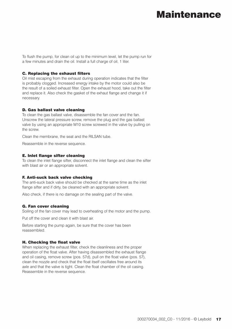
To flush the pump, for clean oil up to the minimum level, let the pump run for a few minutes and drain the oil. Install a full charge of oil, 1 liter.
C. Replacing the exhaust filtersOil mist escaping from the exhaust during operation indicates that the filter is probably clogged. Increased energy intake by the motor could also be the result of a soiled exhaust filter. Open the exhaust hood, take out the filter and replace it. Also check the gasket of the exhaut flange and change it if necessary.
D. Gas ballast valve cleaning To clean the gas ballast valve, disassemble the fan cover and the fan. Unscrew the lateral pressure screw, remove the plug and the gas ballast valve by using an appropriate M10 screw screwed in the valve by pulling on the screw.
Clean the membrane, the seat and the RILSAN tube.
Reassemble in the reverse sequence.
E. Inlet flange sifter cleaning To clean the inlet flange sifter, disconnect the inlet flange and clean the sifter with blast air or an appropriate solvent.
F. Anti-suck back valve checking The anti-suck back valve should be checked at the same time as the inlet flange sifter and if dirty, be cleaned with an appropriate solvent.
Also check, if there is no damage on the sealing part of the valve.
G. Fan cover cleaningSoiling of the fan cover may lead to overheating of the motor and the pump.
Put off the cover and clean it with blast air.
Before starting the pump again, be sure that the cover has been reassembled.
H. Checking the float valve When replacing the exhaust filter, check the cleanliness and the proper operation of the float valve. After having disassembled the exhaust flange and oil casing, remove screw (pos. 57d), pull on the float valve (pos. 57), clean the nozzle and check that the float itself oscillates free around its axle and that the valve is tight. Clean the float chamber of the oil casing. Reassemble in the reverse sequence.

18 300270034_002_C0 - 11/2016 - © Leybold
Troubleshooting
6 Troubleshooting
Fault Possible cause Remedy Reference section *
Pump does not Pump is connected incorrectly. Connect the pump correctly. 3.3 start. Motor protection switch incorrectly set. Set motor protection switch properly. 3.3 Operating voltage does not match motor. Replace the motor. Motor is malfunctioning. Replace the motor. Oil temperature is below 12 °C (54 °F). Heat the pump and pump oil or use 1.4 different oil. Oil is too viscous. Use appropriate oil grade. 5.4-B Exhaust filter / exhaust line is clogged. Replace the filter or clean the exhaust line. 5.4-D
Pump does not External leak Repair the pump. reach ultimate Float valve does not close. Repair the valve. 5.4-H pressure. Anti-suckback valve is malfunctioning. Repair the valve. 5.4-F Inadequate lubrication due to: ■ unsuitable or contaminated oil, Change the oil (degas it, if necessary). 5.4-C ■ clogged oil filter, Replace the oil filter. 5.4-C ■ clogged oil lines. Clean the oil casing. Vacuum lines are dirty. Clean vacuum lines. Pump is too small. Check the process date; replace the pump, if necessary.
Pumping speed is Dirt trap in the intake port is clogged. Clean the dirt trap ; 5.4-E/1.2/3.2 too low. Precaution : install a dust filter in intake line. Exhaust filter is clogged. Install new filter elements. 5.4-D Connecting lines are too narrow or Use adequately wide and short 3.2 too long. connecting lines. Anti-suckback valve is hard to open. Check spring free length.
After switching off System has a leak. Check the system. pump under Anti-suckback is malfunctioning. Repair the valve. 5.4-F vacuum, pressure in system rises too fast.
Pump gets too Cooling air supply is obstructed. Set pump up correctly. 3.1 hot Cooler is dirty. Clean the cooler. Ambient temperature is too high. Set pump up correctly. 3.1 Process gas is too hot. Change the process. Oil level is too low. Add oil to reach the correct oil level. 5.4-C Oil is unsuitable. Change the oil. 5.4-C Oil cycle is obstructed. Clean or repair the oil lines. Exhaust filter / exhaust line is obstructed. Replace the exhaust filter, clean the 5.4-D exhaust line. Pump module is no longer usable. Replace the pump module. 5.4-K

19300270034_002_C0 - 11/2016 - © Leybold
Troubleshooting
Fault Possible cause Remedy Reference section *
Oil in intake line Oil comes from the vacuum system. Check the vacuum system. or in vacuum Anti-suckback valve is obstructed. Clean or repair the valve. 5.4-F vessel. Sealing surfaces of anti-suckback valve Clean or repair the intake port and valve. 5.4-F are damaged or dirty. Oil level is too high. Drain the excess oil. 5.4-B
Pump’s oil Exhaust filters are clogged or damaged. Replace the filters. 5.4-C consumption too Nozzle of float valve is clogged. Check the valve, clean the nozzle. 5.4 high, oil mist at Oil level is too high. Drain the excess oil. 5.4-B exhaust.
Oil is turbid. Condensation. Degas the oil or change the oil and clean 4.1/5.4-B the pump. Precaution : open the gas ballast valve or insert a condensate trap. Clean the gas ballast intake filter. 5.4-G
Pump is Oil level is very low Add oil. 5.4-B excessively noisy. (oil is no longer visible). Oil filter is clogged. Change the oil and filter. 5.4-B Large vacuum leak in system. Repair vacuum leak. Contact Leybold. * Reference section : This column refers to the section in the Operating Instructions that contains the applicable repair information.
Never mount used seals. Always mount new seals.

20 300270034_002_C0 - 11/2016 - © Leybold
Spare parts
7 Spare partsTo guarantee safe operation of the Leybold pump, only original spare parts and accessories should be used. When ordering spare parts and accessories, always state pump type and serial number. You can find part numbers in the spare parts list.
Consumables and main spare parts kits for Sogevac® pumps are usually available on stock at Leybold’s service centers. The list of these parts is given hereafter and in the spare parts table where the contents of each kit is detailed.
■ Exhaust demisters
■ Oil
■ Service kit
■ Set of seals
■ Repair kit
We recommend to use these kits which have been defined to allow an optimal maintenance or repair. Individual spare parts may need longer delivery time.

21300270034_002_C0 - 11/2016 - © Leybold
Spare parts
fig. 3
SV40 BI
M
odifi
e pa
r : F
REI
SSIN
ET
Le :
08.1
2.20
08
Num
:
Vérif
ié p
ar :
LB
Ed
itée
: 08.
12.2
008
LIST
E PI
ECES
DE
REC
HA
NG
ES 9
6033
1V30
07
9714
5213
0/A
2 Pa
ge: 2
/2
23
56
7
11
8
910
11a
1314
1615
1819
22
23d
23i
23b
27282930313253334363738 35
4243
44
48a
48
58a
5852
4053
5554
57b
57a
5759
46
17
6
23
25
23c
2623
h
12a
11b
12 11b
11c
11e
41
11d
50
39
23e
23g
23a23
j
23m
23p
23n
9603
31V3
007
4951
23f
11g
11f
60
456
39

22 300270034_002_C0 - 11/2016 - © Leybold
Spare parts
Pos.
Stück.
Qty Qté
BENENNUNG SPECIFICATION DESIGNATION Abmessungen (mm) Dimensions (mm) Dimensions (mm)
Bestell-Nr Ref, No, N° de réf
Bemerkungen Notes
Remarques
9714
5215
0 97
1443
150
9714
5460
0 97
1427
660
1 1 GEHÄUSEDECKEL MODULE COVER CAPOT POMPE 971424850
2 3 SCHRAUBE SCREW VIS BOMBEE PLATE HC M6X12
3 1 SCHUTZBLECH PROTECTIVE COVER GRILLE PROTECTION POMPE 971424860
4 1 LUEFTER COOLING FAN HELICE DE REFROIDISSEMENT 971424870
5 8 SCHRAUBE SCREW VIS CHC M8 X 30 Q8.8
6 10 UNTERLEGSCHEIBE WASHER RONDELLE W8
7 1 RADIAL-DICHTRING RADIAL SHAFT SEAL JOINT A LEVRE D25/D47X6 71421000
8 1 LAGERDECKEL MIT GB END PLATE WITH GB FLASQUE BAGUE AVEC L.A 971454590 Incl.7,11,12,13,14, 17,18
9 1 SCHRAUBE SCREW VIS BOUT CONIQUE HC M6X10 Q8.8
10 1 SCHRAUBE SCREW VIS INDEXAGE M6 971424710
11 1 GASBALLASTVENTIL6WELLE
GAS BALLAST VALVE SHAFT COMMANDE LEST D AIR 971454560 Incl.
10,11a,b,c,d,e,f,g
11a 1 O-RING O-RING JOINT TOR D4.42
11b 2 O-RING O-RING JOINT TOR D10.77
11c 1 FEDER SPRING RESSORT
11d 1 UNTERLEGSCHEIBE WASHER RONDELLE M8
11e 1 SICHERUNGSRING LOCKING RING CIRCLIPS D18 type 7000
11f 1 GRIFF HANDLE POIGNEE
11g 1 MUTTER NYLSTOP BLOCKING NUT ECROU FREIN M8
12 1 GASBALLAST GAS BALLAST LEST AIR 971450810 Incl. 9,11b,12a
12a 1 MEMBRANE MEMBRANE MEMBRANE D12 X 2 70SH
13 1 RILSAN LEITUNG RILSAN TUBE TUBE RILSAN D4/6 LG165
14 1 SPANNRING CLAMPING RING COLLIER DE FIXATION DN8
15 1 ANKER MIT RINGEN ROTOR WITH RINGS ROTOR BAGUE 971442640 Incl. 23b,c,d,e,f,g
16 1 SCHIEBER SATZ VON 3 VANES SET OF 3 JEU DE 3 PALETTES 971429680
17 2 O-RING O-RING JOINT TOR D9.12
18 1 O-RING O-RING JOINT TOR D110.72
19 3 GUMMIFUSS RUBBER MOUNT AMORTISSEUR DN30 H25 71212640
22 1 RADIAL-DICHTRING RADIAL SHAFT SEAL JOINT A LEVRE D35/D52X6 71420820
23 1 MOTOR MOTOR MOTEUR 1.5/1.8KW 50/60HZ 230V 971455010 Incl.23a,b,c,d,e,f,g,h
,i,j,m,n,p,25,26
23a 1 ELEKTRISCHER ROTOR ELECTRICAL ROTOR ROTOR ELECTRIQUE
23b 1 MOTOR RING MOTOR RING BAGUE ROTOR ELEC.
23c 1 HEBEOESE VERLAENGERUNG LIFTING LUG EXTENSION ENTRETOISE MOTEUR
23d 1 KUGELLAGER MOTOR BALL BEARING MOTOR ROULEMENT BILLES D25XD47X12
23e 1 UNTERLEGSCHEIBE STOP WASHER RONDELLE FREIN MB 5
23f 1 MUTTER NUT ECROU A ENCOCHES KM5 M25X1.5
23g 1 O-RING O-RING JOINT TOR D47.29
23h 1 HINTERE LAGERDECKEL MOTOR REAR END PLATE MOTOR FLASQUE ARRIERE
MOTEUR
23i 1 STIFTSCHRAUBEN (SATZ VON 4) TIE ROD (SET OF 4) TIRANT MOTEUR (JEU DE 4)
23j 1 SCHALTER 24VDC POWER RELAY 24VDC RELAIS DE PUISSANCE 24VDC 971455850
23m 1 ANLAUF KONDENSATOR STARTING CONDENSER CONDENSATEUR DE DEMARRAGE 120µf 971452700
23n 1 PERMANENT KONDENSATOR
PERMANENT CONDENSER
CONDENSATEUR PERMANENT 40µf 971458950
23p 1 ANLAUF RELAIS STARTING RELAY RELAIS DE DEMARRAGE 71414220
25 1 MOTOR LÜFTER MOTOR FAN VENTILATEUR MOTEUR 971442850
26 1 MOTOR LÜFTERHAUBE MOTOR FAN COVER CAPOT MOTEUR 71421910
27 1 HEBEOESE VERLAENGERUNG LIFTING LUG EXTENSION REHAUSSE ANNEAU DE
LEVAGE H110
28 1 HEBEOESE LIFTING LUG ANNEAU DE LEVAGE M8
29 1 O-RING O-RING JOINT TOR D82.14
30 1 FEDER SPRING RESSORT CLAPET ASPIRATION 71212400
31 1 ANSAUGVENTIL INTAKE VALVE CLAPET ASPI. 71015460
32 1 ANSAUGFLANSCH INTAKE FLANGE BRIDE ASPI. EMB.
33 1 O-RING O-RING JOINT TOR D50
34 1 O-RING O-RING JOINT TOR D42
35 1 FILTER FILTER FILTRE EMBOUTI DN45 71407290
36 1 ANSAUGFLANSCH INTAKE FLANGE BRIDE DE RACCORDEMENT 25KF 971461420
37 4 BOLZEN STUD GOUJON M8-25/15J=12 Q6.8
38 4 UNTERLEG SCHEIBE WASHER RONDELLE Z8

23300270034_002_C0 - 11/2016 - © Leybold
LISTE PIECES DE RECHANGE 960331V3007 FREISSINET P. LE : 31.10.2008 971452130/A2
Pos.
Stück.
Qty Qté
BENENNUNG SPECIFICATION DESIGNATION Abmessungen (mm) Dimensions (mm) Dimensions (mm)
Bestell-Nr Ref, No, N° de réf
Bemerkungen Notes
Remarques
9714
5215
0 97
1443
150
9714
5460
0 97
1427
660
39 8 MUTTER NUT ECROU H M8 Q6
40 1 O-RING O-RING JOINT TOR D42.86
42 4 SCHRAUBE SCREW VIS CHC M8X12 Q8.8
43 1 VENTILANSCHLAG VALVE STOP CONTRE LAME
44 1 VENTILPLATTE VALVE LAME
45 1 O-RING O-RING JOINT DE FORME
46 1 ÖLSCHAUGLAS OIL LEVEL GLASS VOYANT HUILE G3/4 71219480
48 1 STOPFEN + O-RING PLUG + O-RING BOUCHON G3/4 971448930 Incl. 48a
48a 1 O-RING O-RING JOINT TOR D27
49 1 SCHLAUCHANSCHLUSS HOSE CONNECTION DOUILLE CANNELEE DN13 - 3/8
50 1 STOPFEN + O-RING PLUG + O-RING BOUCHON G1 1/4 M - 3/8 F 971444130 Incl.40, 49
51 4 SCHRAUBE SCREW VIS CHC M8X20
52 1 AUSPUFFFLANSCH EXHAUST FLANGE BRIDE REFOULEMENT G1 1/4 971453750 Incl. 51,53
53 1 O-RING O-RING JOINT TOR BRIDE REFOULEMENT D108
54 1 FEDER KOMPLETT SPRING UNIT RESSORT DE COMPRESSION ENS. 71420370
55 1 AUSPUFF-FILTER MIT BYPASS
EXHAUST FILTER WITH BYPASS
CARTOUCHE REFOUL. AVEC BY-PASS 971471470 Incl. 53
57 1 SCHWIMMER KOMPLETT FLOAT COMPL. FLOTTEUR
57a 1 ÖLRÜCKFÜHRVENTILKLAPPE OIL RETURN VALVE SEAL CLAPET RECUPERATION
HUILE
57b 1 O-RING O-RING JOINT TOR D8
58 1 STOPFEN + O-RING PLUG + O-RING BOUCHON AVEC JOINT G 1 971448940 Incl. 58a
58a 1 O-RING O-RING JOINT TOR D33
59 1 ÖLKASTEN OHNE ÖLFILTER
OIL CASING WITHOUT OIL FILTER
CARTER SANS FILTRE A HUILE EQ. 971443290 Incl. 45
60 1 SCHALTERKABEL 24 V DC 3 m
RELAIS CABLE 24 V DC 3 m CABLE RELAIS 24 VDC 3 m 971455450
DICHTUNGSSATZ SET OF SEALS JEU DE JOINTS 971452150
REPARATUR KIT REPAIR KIT KIT REPARATION 971452300 PUMPENTEIL KOMPL. MIT GB
VACUUM GENERATOR WITH GB GENERATEUR DE VIDE LA 971454600
WARTUNGSSATZ SERVICE KIT KIT DE MAINTENANCE 971427660
Spare parts

24 300270034_002_C0 - 11/2016 - © Leybold
EU Declaration of Conformity
25300270034_002_C0 - 11/2016 - © Leybold
17200001_002_C0 © Leybold
Declaration of Contamination of Compressors, Vacuum Pumps and Components The repair and / or servicing of compressors, va cuum pumps and components will be carried out only if a correctly completed declaration hasbeen submitted. Non-completion will result in delay. The manufacturer can refuse to accept any equipment without a declaration. A separate declaration has to be completed for each single component.This declaration may be completed and signed only by authorized and qualified staff.
Customer/Dep./Institute : Reason for return: applicable please markAddress : Repair: chargeable warranty Exchange: chargeable warranty Exchange already arranged / received Person to contact: Return only: rent loan for credit Phone : Fax: Calibration: DKD Factory-calibr. End user: Quality test certificate DIN 55350-18-4.2.1
A. Description of the Leybold product: Failure description:
Material description : Catalog number: Additional parts: Serial number: Application-Tool: Type of oil (ForeVacuum-Pumps) : Application- Process:
B. Condition of the equipment No1) Yes No Contamination : No1) Yes
11.. Has the equipment been used toxic 2. Drained (Product/service fluid) corrosive 3. All openings sealed airtight flammable 4. Purged explosive 2)
If yes, which cleaning agent radioactive 2) and which method of cleaning microbiological 2)
1) If answered with “No”, go to D. other harmful substances
C. Description of processed substances (Please fill in absolutely)1. What substances have come into contact with the equipment ?
Trade name and / or chemical term of service fluids and substances processed, properties of the substances According to safety data sheet (e.g. toxic, inflammable, corrosive, radioactive)
X Tradename: Chemical name:
a)
b) c) d)
No Yes2. Are these substances harmful ? 3. Dangerous decomposition products when heated ?
If yes, which ? 2) Components contaminated by microbiological, explosive or radioactive products/substances will not be accepted without written
evidence of decontamination.
D. Legally binding declarationI / we hereby declare that the information supplied on this form is accurate and sufficient to judge any contamination level.
Name of authorized person (block letters) :
Date signature of authorized person
firm stamp

26 300270034_002_C0 - 11/2016 - © Leybold
Notes

27300270034_002_C0 - 11/2016 - © Leybold
Notes

HeadquarterLeybold GmbHBonner Strasse 498D-50968 CologneT: +49-(0)221-347-0F: +49-(0)[email protected]
GermanyLeybold GmbHSales, Service, Support Center (3SC)Bonner Strasse 498D-50968 CologneT: +49-(0)221-347 1234F: +49-(0)221-347 [email protected]
Leybold GmbHSales Area NorthBranch Office BerlinIndustriestrasse 10bD-12099 BerlinT: +49-(0)30-435 609 0F: +49-(0)30-435 609 [email protected]
Leybold GmbHSales Office SouthBranch Office MunichKarl-Hammerschmidt-Strasse 34D-85609 Aschheim-DornachT: +49-(0)89-357 33 9-10F: +49-(0)89-357 33 [email protected]@leybold.com
Leybold Dresden GmbHService Competence CenterZur Wetterwarte 50, Haus 304D-01109 DresdenService:T: +49-(0)351-88 55 00F: +49-(0)351-88 55 [email protected]
Europe
Belgium
Leybold Nederland B.V.Belgisch bijkantoorLeuvensesteenweg 542-9AB-1930 ZaventemSales:T: +32-2-711 00 83F: +32-2-720 83 [email protected]:T: +32-2-711 00 82F: +32-2-720 83 [email protected]
France
Leybold France S.A.S.Parc du Technopolis, Bâtiment Beta3, Avenue du CanadaF-91940 Les Ulis cedexSales and Service:T: +33-1-69 82 48 00F: +33-1-69 07 57 [email protected]@leybold.com
Leybold France S.A.S.Valence Factory640, Rue A. BergèsB.P. 107F-26501 Bourg-lès-Valence CedexT: +33-4-75 82 33 00F: +33-4-75 82 92 [email protected]
Great Britain
Leybold UK LTD.Unit 9Silverglade Business ParkLeatherhead RoadChessingtonSurrey (London)KT9 2QLSales:T: +44-13-7273 7300F: +44-13-7273 [email protected]:T: +44-13-7273 7320F: +44-13-7273 [email protected]
Italy
Leybold Italia S.r.l.Via Trasimeno 8I-20128 MailandSales:T: +39-02-27 22 31F: +39-02-27 20 96 [email protected]:T: +39-02-27 22 31F: +39-02-27 22 32 [email protected]
Netherlands
Leybold Nederland B.V.Floridadreef 102NL-3565 AM UtrechtSales and Service:T: +31-(30) 242 63 30F: +31-(30) 242 63 [email protected]@leybold.com
Switzerland
Leybold Schweiz AG, PfäffikonChurerstrasse 120CH-8808 PfäffikonWarehouse and shipping address:Riedthofstrasse 214CH-8105 RegensdorfSales:T: +41-44-308 40 50F: +41-44-302 43 [email protected]:T: +41-44-308 40 62F: +41-44-308 40 [email protected]
Spain
Leybold Spain, S.A.C/. Huelva, 7E-08940 Cornellà de Llobregat(Barcelona)Sales:T: +34-93-666 43 11F: +34-93-666 43 [email protected]:T: +34-93-666 46 11F: +34-93-685 43 [email protected]
AmericaUSA
Leybold USA Inc.5700 Mellon RoadUSA-Export, PA 15632T: +1-724-327-5700F: [email protected]:T: +1-724-327-5700F: +1-724-333-1217Service:T: +1-724-327-5700F: +1-724-325-3577
Brazil
Leybold do BrasilRod. Vice-Prefeito Hermenegildo Tonolli,nº. 4413 - 6BDistrito IndustrialJundiaí - SPCEP 13.213-086Sales and Service:T: +55 11 3395 3180F: +55 11 99467 [email protected]@leybold.com
AsiaP. R. China
Leybold (Tianjin)International Trade Co. Ltd.Beichen EconomicDevelopment Area (BEDA),No. 8 Western Shuangchen RoadTianjin 300400ChinaSales and Service:T: +86-22-2697 0808F: +86-22-2697 4061F: +86-22-2697 [email protected]@leybold.com
India
Leybold India Pvt Ltd.No. 82(P), 4th PhaseK.I.A.D.B. PlotBommasandra Industrial AreaBangalore - 560 099IndienSales and Service:T: +91-80-2783 9925F: +91-80-2783 [email protected]@leybold.com
Japan
Leybold Japan Co., Ltd.HeadquartersShin-Yokohama A.K.Bldg., 4th floor3-23-3, Shin-YokohamaKohoku-ku, Yokohama-shiKanawaga 222-0033JapanSales:T: +81-45-471-3330F: [email protected]
Leybold Japan Co., Ltd.Tsukuba Technical Service Center1959, Kami-yokobaTsukuba-shi, Ibaraki-shi 305-0854JapanService:T: +81-29 839 5480F: +81-29 839 [email protected]
Malaysia
Leybold MalaysiaLeybold Singapore Pte Ltd.No. 1 Jalan Hi-Tech 2/6Kulim Hi-Tech ParkKulim, Kedah DarulAman 09000MalaysiaSales and Service:T: +604 4020 222F: +604 4020 [email protected]@leybold.com
South Korea
Leybold Korea Ltd.3F. Jellzone 2 TowerJeongja-dong 159-4Bundang-gu Sungnam-siGyeonggi-doBundang 463-384, KoreaSales:T: +82-31 785 1367F: +82-31 785 [email protected]:623-7, Upsung-DongCheonan-SiChungcheongnam-DoKorea 330-290T: +82-41 589 3035F: +82-41 588 [email protected]
Singapore
Leybold Singapore Pte Ltd.8 Commonwealth Lane #01-01Singapore 149555SingaporeSales and Service:T: +65-6303 7030F: +65-6773 [email protected]@leybold.com
Taiwan
Leybold Taiwan Ltd.No 416-1, Sec. 3Chunghsin Rd., ChutungHsinchu County 310Taiwan, R.O.C.Sales and Service:T: +886-3-500 1688F: +886-3-583 [email protected]@leybold.com
Sales and ServiceLV
_137
86_2
016
10.1
6