syllabus details and associated learning … navigation_eir.pdfsyllabus details and associated...
TRANSCRIPT

Syllabus reference
Syllabus details and associated Learning Objectives CB-IR (A)
and
EIR
062 00 00 00 RADIO NAVIGATION
062 02 00 00 RADIO AIDS
062 02 01 00 Ground D/F
062 02 01 03 Coverage and range
LO Use the formula, 1,23 x √transmitter height in feet + 1,23 x √receiver height in feet, to calculate the range in NM
x
062 02 02 00 NDB/ADF
062 02 02 01 Principles
LO Define the abbreviation NDB Non Directional Beacon x
LO Define the abbreviation ADF Automatic Direction Finder x
LO State that the NDB is the ground part of the system x
LO State that the ADF is the airborne part of the system x
LO State that NDB operates in the LF and MF frequency bands x
LO The frequency band assigned to aeronautical NDBs according to ICAO Annex 10 is
190–1750 kHz
x
LO Define a locator beacon. An LF/MF NDB used as an aid to final approach usually with a range, according to ICAO Annex 10, of 10–25 NM
x
LO Explain the difference between NDBs and locator beacons x
LO Explain which beacons transmit signals suitable for use by an ADF x
LO State that certain commercial radio stations transmit within the frequency band of the NDB x
Syllabus reference
Syllabus details and associated Learning Objectives CB-IR (A)
and
EIR
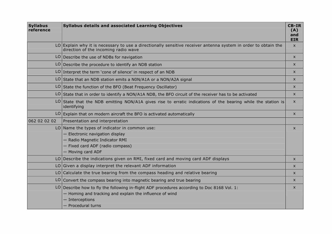
LO Explain why it is necessary to use a directionally sensitive receiver antenna system in order to obtain the direction of the incoming radio wave
x
LO Describe the use of NDBs for navigation x
LO Describe the procedure to identify an NDB station x
LO Interpret the term ‘cone of silence’ in respect of an NDB x
LO State that an NDB station emits a N0N/A1A or a NON/A2A signal x
LO State the function of the BFO (Beat Frequency Oscillator) x
LO State that in order to identify a NON/A1A NDB, the BFO circuit of the receiver has to be activated x
LO State that the NDB emitting NON/A1A gives rise to erratic indications of the bearing while the station is
identifying
x
LO Explain that on modern aircraft the BFO is activated automatically x
062 02 02 02 Presentation and interpretation
LO Name the types of indicator in common use:
— Electronic navigation display
— Radio Magnetic Indicator RMI
— Fixed card ADF (radio compass)
— Moving card ADF
x
LO Describe the indications given on RMI, fixed card and moving card ADF displays x
LO Given a display interpret the relevant ADF information x
LO Calculate the true bearing from the compass heading and relative bearing x
LO Convert the compass bearing into magnetic bearing and true bearing x
LO Describe how to fly the following in-flight ADF procedures according to Doc 8168 Vol. 1:
— Homing and tracking and explain the influence of wind
— Interceptions
— Procedural turns
x
Syllabus reference
Syllabus details and associated Learning Objectives CB-IR (A)
and
EIR
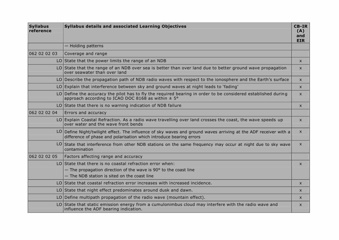
— Holding patterns
062 02 02 03 Coverage and range
LO State that the power limits the range of an NDB x
LO State that the range of an NDB over sea is better than over land due to better ground wave propagation over seawater than over land
x
LO Describe the propagation path of NDB radio waves with respect to the ionosphere and the Earth’s surface x
LO Explain that interference between sky and ground waves at night leads to ‘fading’ x
LO Define the accuracy the pilot has to fly the required bearing in order to be considered established during approach according to ICAO DOC 8168 as within ± 5°
x
LO State that there is no warning indication of NDB failure x
062 02 02 04 Errors and accuracy
LO Explain Coastal Refraction. As a radio wave travelling over land crosses the coast, the wave speeds up over water and the wave front bends
x
LO Define Night/twilight effect. The influence of sky waves and ground waves arriving at the ADF receiver with a
difference of phase and polarisation which introduce bearing errors
x
LO State that interference from other NDB stations on the same frequency may occur at night due to sky wave
contamination
x
062 02 02 05 Factors affecting range and accuracy
LO State that there is no coastal refraction error when:
— The propagation direction of the wave is 90° to the coast line
— The NDB station is sited on the coast line
x
LO State that coastal refraction error increases with increased incidence. x
LO State that night effect predominates around dusk and dawn. x
LO Define multipath propagation of the radio wave (mountain effect). x
LO State that static emission energy from a cumulonimbus cloud may interfere with the radio wave and influence the ADF bearing indication.
x

Syllabus reference
Syllabus details and associated Learning Objectives CB-IR (A)
and
EIR
062 02 03 00 VOR and Doppler-VOR
062 02 03 01 Principles
LO State that the frequency band allocated to VOR according to ICAO Annex 10 is VHF and the frequencies used are 108.0–117.975 MHz.
x
LO State that frequencies in the allocated VOR range with the first decimal place an odd number, are used by ILS
x
LO State that the following types of VOR are in operation:
— Conventional VOR (CVOR) a first generation VOR station emitting signals by means of a rotating antenna
— Doppler VOR (DVOR) a second generation VOR station emitting signals by means of a combination of fixed
antennas utilising the Doppler principle
— En-route VOR for use by IFR traffic
— Terminal VOR (TVOR) a station with a shorter range used as part of the approach and departure structure
at major airports
— Test VOR (VOT) a VOR station emitting a signal to test VOR indicators in an aircraft
x
LO Describe how ATIS information is transmitted on VOR frequencies. x
LO List the three main components of VOR airborne equipment:
— The antenna
— The receiver
— The indicator
x
LO Describe the identification of a VOR in terms of Morse-code letters, continuous tone or dots (VOT), tone pitch, repetition rate and additional plain text
x
LO State that failure of the VOR station to stay within the required limits can cause the removal of identification and navigation components from the carrier or radiation to cease
x
062 02 03 02 Presentation and interpretation
LO Read off the radial on a Radio Magnetic Indicator (RMI) x
LO Read off the angular displacement, in relation to a pre-selected radial on an HSI or CDI x
LO Explain the use of the TO/FROM indicator in order to determine aircraft position relative to the VOR x

Syllabus reference
Syllabus details and associated Learning Objectives CB-IR (A)
and
EIR considering also the heading of the aircraft
LO Interpret VOR information as displayed on HSI, CDI and RMI x
LO Describe the following in-flight VOR procedures as in DOC 8168 Vol.1:
— Tracking and explain the influence of wind when tracking
— Interceptions
— Procedural turns
— Holding patterns
x
LO State that when converting a radial into a true bearing, the variation at the VOR station has to be taken into account
x
062 02 03 03 Coverage and Range
LO Calculate the range using the formula:
1,23 x √transmitter height in feet + 1,23 x √receiver height in feet
x
062 02 03 04 Errors and accuracy
LO Define the accuracy the pilot has to fly the required bearing in order to be considered established on a VOR track when flying approach procedures according to ICAO Doc 8168 as within half full scale deflection of the required track
x
LO
State that due to reflections from terrain, radials can be bent and lead to wrong or fluctuating indications which is called ‘scalloping’.
x
062 02 04 00 DME
062 02 04 01 Principles
LO State that DME operates in the UHF band between 960–1215 MHz according to ICAO Annex 10 x
LO State that the system comprises two basic components:
— The aircraft component, the interrogator
— The ground component, the transponder
x
LO State that the distance measured by DME is slant range x
LO Illustrate that a position line using DME is a circle with the station at its centre x

Syllabus reference
Syllabus details and associated Learning Objectives CB-IR (A)
and
EIR
LO Describe how the pairing of VHF and UHF frequencies (VOR/DME) enables selection of two items of navigation information from one frequency setting
x
LO Describe, in the case of co-location, the frequency pairing and identification procedure x
LO Explain that depending on the configuration, the combination of a DME distance with a VOR radial can determine the position of the aircraft
x
LO Explain that military TACAN stations may be used for DME information x
062 02 04 02 Presentation and interpretation
LO Explain that when identifying a DME station co-located with a VOR station, the identification signal with the higher tone frequency is the DME which idents approximately every 40 seconds
x
LO Calculate ground distance given slant range and altitude x
LO Describe the use of DME to fly a DME arc in accordance with DOC 8168 Vol. 1 x
LO State that a DME system may have a groundspeed read out combined with the DME read out x
062 02 04 03 Coverage and Range
LO Explain why a ground station can generally respond to a maximum of 100 aircraft. x
LO Explain which aircraft will be denied a DME range first when more than 100 interrogations are being made
x
062 02 04 05 Factors affecting range and accuracy
LO State that the groundspeed read out combined with DME is only correct when tracking directly to or from the DME station
x
LO State that, close to the station, the groundspeed read out combined with DME is less than the actual groundspeed
x
062 02 05 00 ILS
062 02 05 01 Principles
LO Name the three main components of an ILS:
— The localiser (LLZ)
— The glide path (GP)
— Range information (markers or DME)
x

Syllabus reference
Syllabus details and associated Learning Objectives CB-IR (A)
and
EIR
LO State the site locations of the ILS components:
— The localiser antenna should be located on the extension of the runway centre line at the stop-end
— The glide path antenna should be located 300 metres beyond the runway threshold, laterally displaced
approximately 120 metres to the side of the runway centre line
x
LO Explain that marker beacons produce radiation patterns to indicate predetermined distances from the threshold along the ILS glide path
x
LO Explain that marker beacons are sometimes replaced by a DME paired with the LLZ frequency x
LO State that in the ILS frequency assigned band 108,0–111,975 MHz, only frequencies with the first decimal odd are ILS frequencies
x
LO State that the LLZ operates in the VHF band 108,0–111,975 MHz according to ICAO Annex 10 x
LO State that the GP operates in the UHF band x
LO State that both the LLZ and the GP antenna radiate side lobes (false beams) which could give rise to false centreline and false glide path indication
x
LO Explain that the back beam from the LLZ antenna may be used as a published ‘non-precision approach’ x
LO State that according to ICAO Annex 10 the nominal glide path is 3° x
LO State that according to ICAO DOC 8168, the final approach area contains a fix or facility that permits verification of the ILS glide path/altimeter relationship. The outer marker or DME is usually used for this purpose.
x
062 02 05 02 Presentation and interpretation
LO Describe the ILS identification regarding frequency and Morse code and/or plain text x
LO Calculate the rate of descent for a 3° glide path angle given the groundspeed of the aircraft using the formula:
Rate of descent (ROD) in ft/min = groundspeed in kt x 10 2
x
LO Calculate the rate of descent using the following formula when flying any glide path angle:
ROD ft/min = Speed factor (SF) x glide path angle x 100
x
LO Interpret the markers by sound, modulation, and frequency x
Syllabus reference
Syllabus details and associated Learning Objectives CB-IR (A)
and
EIR
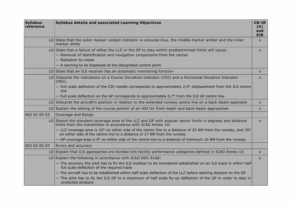
LO State that the outer marker cockpit indicator is coloured blue, the middle marker amber and the inner marker white
x
LO State that a failure of either the LLZ or the GP to stay within predetermined limits will cause:
— Removal of identification and navigation components from the carrier
— Radiation to cease
— A warning to be displayed at the designated control point
x
LO State that an ILS receiver has an automatic monitoring function x
LO Interpret the indications on a Course Deviation Indicator (CDI) and a Horizontal Situation Indicator (HSI):
— Full scale deflection of the CDI needle corresponds to approximately 2,5° displacement from the ILS centre
line
— Full scale deflection on the GP corresponds to approximately 0,7° from the ILS GP centre line
x
LO Interpret the aircraft’s position in relation to the extended runway centre line on a back-beam approach x
LO Explain the setting of the course pointer of an HSI for front-beam and back-beam approaches x
062 02 05 03 Coverage and Range
LO Sketch the standard coverage area of the LLZ and GP with angular sector limits in degrees and distance limits from the transmitter in accordance with ICAO Annex 10:
— LLZ coverage area is 10° on either side of the centre line to a distance of 25 NM from the runway, and 35°
on either side of the centre line to a distance of 17 NM from the runway
— GP coverage area is 8° on either side of the centre line to a distance of minimum 10 NM from the runway
x
062 02 05 04 Errors and accuracy
LO Explain that ILS approaches are divided into facility performance categories defined in ICAO Annex 10 x
LO Explain the following in accordance with ICAO DOC 8168:
— The accuracy the pilot has to fly the ILS localiser to be considered established on an ILS track is within half
full scale deflection of the required track
— The aircraft has to be established within half scale deflection of the LLZ before starting descent on the GP
— The pilot has to fly the ILS GP to a maximum of half scale fly-up deflection of the GP in order to stay in
protected airspace
x

Syllabus reference
Syllabus details and associated Learning Objectives CB-IR (A)
and
EIR
LO State that if a pilot deviates by more than half scale deflection on the LLZ or by more than half course fly-up deflection on the GP, an immediate missed approach should be executed, because obstacle clearance may no longer be guaranteed
x
062 03 00 00 RADAR
062 03 01 00 Pulse techniques and associated terms
LO Name the different applications of radar with respect to ATC, MET observations and airborne weather radar
x
LO Describe the pulse technique and echo principle on which primary radar systems are based. x
LO Describe, in general terms, the effects of the following factors with respect to the quality of the target
depiction on the radar display:
— Atmospheric conditions; super refraction and sub refraction
— Attenuation with distance
— Condition and size of the reflecting surface
x
062 03 02 00 Ground Radar
062 03 02 01 Principles
LO Explain that primary radar provides bearing and distance of targets. x
LO Explain that primary ground radar is used to detect aircraft that are not equipped with a secondary radar
transponder.
x
LO Explain why Moving Target Indicator (MTI) is used x
062 03 02 02 Presentation and interpretation
LO State that modern ATC systems use computer generated display. x
LO Explain that the radar display enables the ATS controller to provide information, surveillance or guidance service.
x
062 03 03 00 Airborne Weather Radar
062 03 03 01 Principles
LO List the two main tasks of the weather radar in respect of weather and navigation x

Syllabus reference
Syllabus details and associated Learning Objectives CB-IR (A)
and
EIR
LO Explain how the antenna is attitude-stabilised in relation to the horizontal plane using the aircraft's attitude reference system
x
LO Describe the cone shaped pencil beam of about 3° to 5° beam width used for weather depiction x
LO Explain that in modern AWRs a single radiation pattern is used for both mapping and weather with the scanning angle being changed between them
x
062 03 03 02 Presentation and interpretation
LO Explain the functions of the following different modes on the radar control panel
— Off/on switch
— Function switch, with modes WX, WX+T and MAP.
— Gain control setting (auto/manual)
— Tilt/auto tilt switch.
x
LO Name, for areas of differing reflection intensity, the colour gradations (green, yellow, red and magenta)
indicating the increasing intensity of precipitation
x
LO Illustrate the use of azimuth marker lines and range lines in respect of the relative bearing and the distance to
a thunderstorm or to a landmark on the screen
x
062 03 03 03 Coverage and Range
LO Explain how the radar is used for weather detection and for mapping (range, tilt and gain if available) x
062 03 03 04 Errors, accuracy, limitations
LO Explain why AWR should be used with extreme caution when on the ground x
062 03 03 05 Factors affecting range and accuracy
LO Explain the danger of the area behind heavy rain (shadow area) where no radar waves will penetrate x
LO Explain why the tilt setting should be higher when the aircraft descends to a lower altitude x
LO Explain why the tilt setting should be lower when the aircraft climbs to a higher altitude x
LO Explain why a thunderstorm may not be detected when the tilt is set too high x
062 03 03 06 Application for navigation
Syllabus reference
Syllabus details and associated Learning Objectives CB-IR (A)
and
EIR
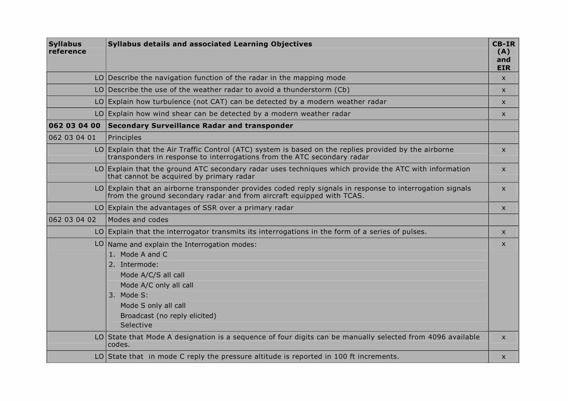
LO Describe the navigation function of the radar in the mapping mode x
LO Describe the use of the weather radar to avoid a thunderstorm (Cb) x
LO Explain how turbulence (not CAT) can be detected by a modern weather radar x
LO Explain how wind shear can be detected by a modern weather radar x
062 03 04 00 Secondary Surveillance Radar and transponder
062 03 04 01 Principles
LO Explain that the Air Traffic Control (ATC) system is based on the replies provided by the airborne transponders in response to interrogations from the ATC secondary radar
x
LO Explain that the ground ATC secondary radar uses techniques which provide the ATC with information that cannot be acquired by primary radar
x
LO Explain that an airborne transponder provides coded reply signals in response to interrogation signals from the ground secondary radar and from aircraft equipped with TCAS.
x
LO Explain the advantages of SSR over a primary radar x
062 03 04 02 Modes and codes
LO Explain that the interrogator transmits its interrogations in the form of a series of pulses. x
LO Name and explain the Interrogation modes:
1. Mode A and C
2. Intermode:
Mode A/C/S all call
Mode A/C only all call
3. Mode S:
Mode S only all call
Broadcast (no reply elicited)
Selective
x
LO State that Mode A designation is a sequence of four digits can be manually selected from 4096 available codes.
x
LO State that in mode C reply the pressure altitude is reported in 100 ft increments. x
Syllabus reference
Syllabus details and associated Learning Objectives CB-IR (A)
and
EIR
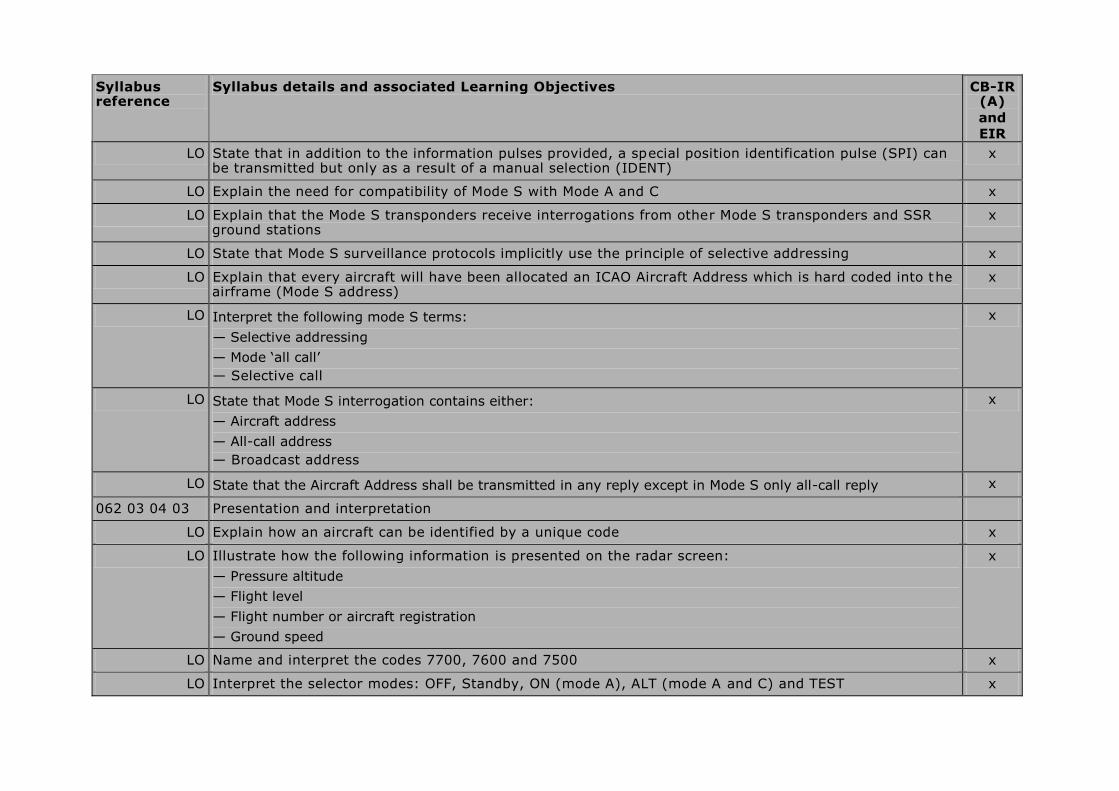
LO State that in addition to the information pulses provided, a special position identification pulse (SPI) can be transmitted but only as a result of a manual selection (IDENT)
x
LO Explain the need for compatibility of Mode S with Mode A and C x
LO Explain that the Mode S transponders receive interrogations from other Mode S transponders and SSR ground stations
x
LO State that Mode S surveillance protocols implicitly use the principle of selective addressing x
LO Explain that every aircraft will have been allocated an ICAO Aircraft Address which is hard coded into the airframe (Mode S address)
x
LO Interpret the following mode S terms:
— Selective addressing
— Mode ‘all call’
— Selective call
x
LO State that Mode S interrogation contains either:
— Aircraft address
— All-call address
— Broadcast address
x
LO State that the Aircraft Address shall be transmitted in any reply except in Mode S only all-call reply x
062 03 04 03 Presentation and interpretation
LO Explain how an aircraft can be identified by a unique code x
LO Illustrate how the following information is presented on the radar screen:
— Pressure altitude
— Flight level
— Flight number or aircraft registration
— Ground speed
x
LO Name and interpret the codes 7700, 7600 and 7500 x
LO Interpret the selector modes: OFF, Standby, ON (mode A), ALT (mode A and C) and TEST x

Syllabus reference
Syllabus details and associated Learning Objectives CB-IR (A)
and
EIR
LO Explain the function of the emission of a SPI (Special Position Identification) pulse after pushing the IDENT button in the aircraft
x
ELEMENTARY SURVEILLANCE
LO Explain that the elementary surveillance provides the ATC controller with aircraft position, altitude and identification
x
LO State that the elementary surveillance needs MODE S transponders with surveillance identifier (SI) code capacity and the automatic reporting of aircraft identification, known as ICAO level 2s
x
LO State that the SI code must correspond to the aircraft identification specified in item 7 of the ICAO flight plan or to the registration marking
x
062 03 04 04 Errors and Accuracy
LO Explain the following disadvantages of SSR (mode A/C):
— Code garbling of aircraft less than 1.7 NM apart measured in the vertical plane perpendicular to and from
the antenna
— ‘Fruiting’ which results from reception of replies caused by interrogations from other radar stations
x
062 05 00 00 AREA NAVIGATION SYSTEMS, RNAV/FMS
062 05 01 00 General philosophy and definitions
062 05 01 01 Basic RNAV (B-RNAV)/precision RNAV (P-RNAV)/ RNP-PNAV
LO Define area navigation RNAV (ICAO Annex 11). A method of navigation permitting aircraft operations on any desired track within the coverage of station-referenced navigation signal, or within the limits of a self-contained navigation system
x
LO State that basic RNAV (B-RNAV) systems require RNP 5 x
LO State that precision RNAV (PRNAV) systems require RNP 1 x
062 05 01 02 Principles of 2D RNAV, 3D RNAV and 4D RNAV
LO State that a 2D RNAV system is able to navigate in the horizontal plane only. x
LO State that a 3D RNAV system is able to navigate in the horizontal plane and in addition has a guidance capability in the vertical plane.
x
LO State that a 4D RNAV system is able to navigate in the horizontal plane, has a guidance capability in the x

Syllabus reference
Syllabus details and associated Learning Objectives CB-IR (A)
and
EIR vertical plane and in addition has a timing function
062 05 01 03 Required Navigation Performance (RNP) in accordance with ICAO DOC 9613
LO State that RNP is a concept that applies to navigation performance within an airspace x
LO The RNP type is based on the navigation performance accuracy to be achieved within the airspace. x
LO State that RNP X requires a navigation performance accuracy of X NM both lateral and longitudinal 95 % of the flying time. (RNP 1 requires a navigation performance of 1 NM both lateral and longitudinal 95 % of the flying time)
x
LO State that RNAV equipment is one requirement, in order to receive approval to operate in a RNP environment
x
LO State that RNAV equipment operates by automatically determining the aircraft position. x
LO State the advantages of using RNAV techniques over more conventional forms of navigation:
— Establishment of more direct routes permitting a reduction in flight distance
— Establishment of dual or parallel routes to accommodate a greater flow of en-route traffic
— Establishment of bypass routes for aircraft over flying high-density terminal areas
— Establishment of alternatives or contingency routes on either a planned or ad hoc basis
— Establishment of optimum locations for holding patterns
— Reduction in the number of ground navigation facilities
x
LO State that RNP may be specified for a route, a number of routes, an area, volume of airspace or any airspace of defined dimensions.
x
LO State that airborne navigation equipment uses inputs from navigational systems such as VOR/DME, DME/DME, GNSS, INS and IRS.
x
LO State that aircraft equipped to operate to RNP 1 and better, should be able to compute an estimate of its position error, depending on the sensors being used and time elapsed
x
LO Indicate navigation equipment failure. x
062 05 02 00 Simple 2D RNAV
Info:
First generation of radio navigation systems allowing the flight crew to select a phantom waypoint on the

Syllabus reference
Syllabus details and associated Learning Objectives CB-IR (A)
and
EIR RNAV panel and select a desired track to fly inbound to the waypoint.
062 05 02 01 Flight deck equipment
LO The control unit allows the flight crew to:
— Tune the VOR/DME station used to define the phantom waypoint
— Define the phantom waypoint as a radial and distance (DME) form the selected VOR/DME station
— Select desired magnetic track to follow inbound to the phantom waypoint
— Select between an en-route mode, an approach mode of operation and the basic VOR/DME mode of operation
x
LO Track guidance is shown on the HSI/CDI. x
062 05 02 02 Navigation computer, VOR/DME navigation
LO The navigation computer of the simple 2D RNAV system computes the navigational problems by simple sine and cosine mathematics, solving the triangular problems.
x
062 05 02 03 Navigation computer input/output
LO State the following input data to the navigation computer is:
— Actual VOR radial and DME distance from selected VOR station
— Radial and distance to phantom waypoint
— Desired magnetic track inbound to the phantom waypoint
x
LO State the following output data from the navigation computer:
— Desired magnetic track to the phantom waypoint shown on the CDI at the course pointer
— Distance from present position to the phantom waypoint
— Deviations from desired track as follows:
— In en-route mode full scale deflection on the CDI is 5 NM
— In approach mode full scale deflection on the CDI is 1¼ NM
— In VOR/DME mode full scale deflection of the CDI is 10.
x
LO State that the system is limited to operate within range of selected VOR/DME station x
062 05 03 00 4D RNAV
Syllabus reference
Syllabus details and associated Learning Objectives CB-IR (A)
and
EIR
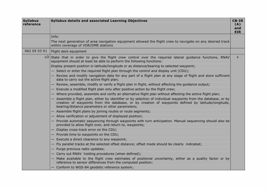
Info:
The next generation of area navigation equipment allowed the flight crew to navigate on any desired track
within coverage of VOR/DME stations
062 05 03 01 Flight deck equipment
LO State that in order to give the flight crew control over the required lateral guidance functions, RNAV
equipment should at least be able to perform the following functions:
Display present position in latitude/longitude or as distance/bearing to selected waypoint;
— Select or enter the required flight plan through the control and display unit (CDU);
— Review and modify navigation data for any part of a flight plan at any stage of flight and store sufficient
data to carry out the active flight plan;
— Review, assemble, modify or verify a flight plan in flight, without affecting the guidance output;
— Execute a modified flight plan only after positive action by the flight crew;
— Where provided, assemble and verify an alternative flight plan without affecting the active flight plan;
— Assemble a flight plan, either by identifier or by selection of individual waypoints from the database, or by
creation of waypoints from the database, or by creation of waypoints defined by latitude/longitude,
bearing/distance parameters or other parameters;
— Assemble flight plans by joining routes or route segments;
— Allow verification or adjustment of displayed position;
— Provide automatic sequencing through waypoints with turn anticipation. Manual sequencing should also be
provided to allow flight over, and return to, waypoints;
— Display cross-track error on the CDU;
— Provide time to waypoints on the CDU;
— Execute a direct clearance to any waypoint;
— Fly parallel tracks at the selected offset distance; offset mode should be clearly indicated;
— Purge previous radio updates;
— Carry out RNAV holding procedures (when defined);
— Make available to the flight crew estimates of positional uncertainty, either as a quality factor or by
reference to sensor differences from the computed position;
— Conform to WGS-84 geodetic reference system;
x

Syllabus reference
Syllabus details and associated Learning Objectives CB-IR (A)
and
EIR
— Indicate navigation equipment failure.
062 05 04 00 FMS and general terms
062 05 04 03 Navigation data base
LO State that the navigation database of the FMC may contain the following data:
— Reference data for airports (four letter ICAO identifier)
— VOR/DME station data (three letter ICAO identifier)
— Waypoint data (five letter ICAO identifier)
— STAR data
— SID data
— Holding patterns
— Airport runway data
— NDB stations (alphabetic ICAO identifier)
— Company flight plan routes
x
LO State that the navigation database is updated every 28 days. x
LO State that the navigational database is write protected, but additional space exists so that crew created navigational data may be saved in the computer memory. Such additional data will also be deleted at the 28 days navigational update of the database.
x
062 05 04 06 Determination of the FMS-position of the aircraft
LO State that modern FMS may use a range of sensors for calculating the position of the aircraft including VOR, DME, GPS, IRS and ILS.
x
062 06 00 00 GLOBAL NAVIGATION SATELLITE SYSTEMS
062 06 01 00 GPS/GLONASS/GALILEO
062 06 01 01 Principles
LO State that there are two main Global Navigation Satellite Systems (GNSS) currently in existence with a third which is planned to be fully operational by 2011. They are:
— USA NAVSTAR GPS (NAVigation System with Timing And Ranging Global Positioning System
x

Syllabus reference
Syllabus details and associated Learning Objectives CB-IR (A)
and
EIR
— Russian GLONASS (GLObal NAvigation Satellite System)
— European GALILEO
LO State that all 3 systems (will) consist of a constellation of satellites which can be used by a suitably equipped receiver to determine position
x
062 06 01 02 Operation
NAVSTAR GPS
LO State that there are currently two modes of operation, SPS (Standard Positioning Service) for civilian users, and PPS (Precise Positioning Service for authorised users
x
LO SPS was originally designed to provide civil users with a less accurate positioning capability than PPS x
LO Name the three segments as:
— Space segment
— Control segment
— User segment
x
Space segment
LO State that the space segment consists of a notional constellation of 24 operational satellites x
LO State that it takes 12½ minutes for a GPS receiver to receive all the data frames in the navigation message
x
LO State that the almanac contains the orbital data about all the satellites in the GPS constellation x
LO State that the ephemeris contains data used to correct the orbital data of the satellites due to small disturbances
x
LO State that the clock correction parameters are data for correction of the satellite time x
LO State that UTC parameters are factors determining the difference between GPS time and UTC x
LO State that an ionospheric model is currently used to calculate the time delay of the signal travelling through the ionosphere.
x
LO State that the GPS health message is used to exclude unhealthy satellites from the position solution. Satellite health is determined by the validity of the navigation data
x
LO State that GPS uses the WGS 84 model x
Syllabus reference
Syllabus details and associated Learning Objectives CB-IR (A)
and
EIR
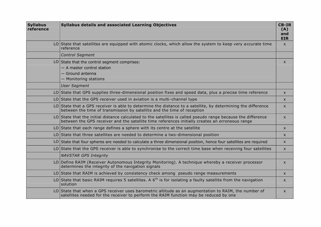
LO State that satellites are equipped with atomic clocks, which allow the system to keep very accurate time reference
x
Control Segment
LO State that the control segment comprises:
— A master control station
— Ground antenna
— Monitoring stations
x
User Segment
LO State that GPS supplies three-dimensional position fixes and speed data, plus a precise time reference x
LO State that the GPS receiver used in aviation is a multi-channel type x
LO State that a GPS receiver is able to determine the distance to a satellite, by determining the difference between the time of transmission by satellite and the time of reception
x
LO State that the initial distance calculated to the satellites is called pseudo range because the difference between the GPS receiver and the satellite time references initially creates an erroneous range
x
LO State that each range defines a sphere with its centre at the satellite x
LO State that three satellites are needed to determine a two-dimensional position x
LO State that four spheres are needed to calculate a three dimensional position, hence four satellites are required x
LO State that the GPS receiver is able to synchronise to the correct time base when receiving four satellites x
NAVSTAR GPS Integrity
LO Define RAIM (Receiver Autonomous Integrity Monitoring). A technique whereby a receiver processor determines the integrity of the navigation signals
x
LO State that RAIM is achieved by consistency check among pseudo range measurements x
LO State that basic RAIM requires 5 satellites. A 6 th is for isolating a faulty satellite from the navigation solution
x
LO State that when a GPS receiver uses barometric altitude as an augmentation to RAIM, the number of satellites needed for the receiver to perform the RAIM function may be reduced by one
x

Syllabus reference
Syllabus details and associated Learning Objectives CB-IR (A)
and
EIR
062 06 01 03 Errors and Factors affecting accuracy
LO List the most significant factors affecting accuracy:
— Ionospheric propagation delay
— Dilution of position
— Satellite clock error
— Satellite orbital variations
— Multipath
x
062 06 02 00 Ground, Satellite and Airborne based augmentation systems
Satellite Based Augmentation Systems (SBAS)
LO Explain the principle of a SBAS : to measure on the ground the signal errors transmitted by GNSS satellites and transmit differential corrections and integrity messages for navigation satellites
x
LO State that the frequency band of the data link is identical to that of the GPS signals. x
LO Explain that the use of geostationary satellites enables messages to be broadcast over very wide areas x
LO Explain that pseudo-range measurements to these geostationary satellites can also be made, as if they were
GPS satellites
x
LO Stat that SBAS consists of 3 elements :
— The ground infrastructure (monitoring and processing stations),
— The SBAS satellites,
— The SBAS airborne receivers.
x
LO Explain that SBAS can provide approach and landing operations with Vertical guidance (APV) and precision approach service .
x
LO Explain the difference between Coverage area and Service area x
LO State that Satellite Based Augmentation Systems include:
— EGNOS in Western Europe and the Mediterranean
— WAAS in USA
— MSAS in Japan
x
Syllabus reference
Syllabus details and associated Learning Objectives CB-IR (A)
and
EIR
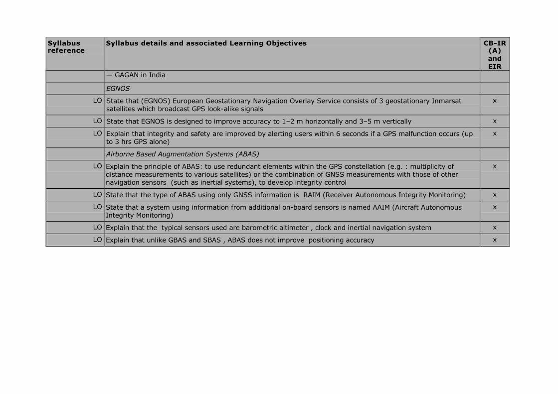
— GAGAN in India
EGNOS
LO State that (EGNOS) European Geostationary Navigation Overlay Service consists of 3 geostationary Inmarsat satellites which broadcast GPS look-alike signals
x
LO State that EGNOS is designed to improve accuracy to 1–2 m horizontally and 3–5 m vertically x
LO Explain that integrity and safety are improved by alerting users within 6 seconds if a GPS malfunction occurs (up to 3 hrs GPS alone)
x
Airborne Based Augmentation Systems (ABAS)
LO Explain the principle of ABAS: to use redundant elements within the GPS constellation (e.g. : multiplicity of distance measurements to various satellites) or the combination of GNSS measurements with those of other navigation sensors (such as inertial systems), to develop integrity control
x
LO State that the type of ABAS using only GNSS information is RAIM (Receiver Autonomous Integrity Monitoring) x
LO State that a system using information from additional on-board sensors is named AAIM (Aircraft Autonomous Integrity Monitoring)
x
LO Explain that the typical sensors used are barometric altimeter , clock and inertial navigation system x
LO Explain that unlike GBAS and SBAS , ABAS does not improve positioning accuracy x