synthesis and characterization of complex polymer
TRANSCRIPT

University of Tennessee, Knoxville University of Tennessee, Knoxville
TRACE: Tennessee Research and Creative TRACE: Tennessee Research and Creative
Exchange Exchange
Doctoral Dissertations Graduate School
12-2006
Synthesis and Characterization of Complex Polymer Architectures Synthesis and Characterization of Complex Polymer Architectures
Brandon Scott Farmer University of Tennessee - Knoxville
Follow this and additional works at: https://trace.tennessee.edu/utk_graddiss
Part of the Chemistry Commons
Recommended Citation Recommended Citation Farmer, Brandon Scott, "Synthesis and Characterization of Complex Polymer Architectures. " PhD diss., University of Tennessee, 2006. https://trace.tennessee.edu/utk_graddiss/1940
This Dissertation is brought to you for free and open access by the Graduate School at TRACE: Tennessee Research and Creative Exchange. It has been accepted for inclusion in Doctoral Dissertations by an authorized administrator of TRACE: Tennessee Research and Creative Exchange. For more information, please contact [email protected].

To the Graduate Council:
I am submitting herewith a dissertation written by Brandon Scott Farmer entitled "Synthesis and
Characterization of Complex Polymer Architectures." I have examined the final electronic copy
of this dissertation for form and content and recommend that it be accepted in partial
fulfillment of the requirements for the degree of Doctor of Philosophy, with a major in Chemistry.
Jimmy W. Mays, Major Professor
We have read this dissertation and recommend its acceptance:
Mark Dadmun, John Turner, Roberto Benson
Accepted for the Council:
Carolyn R. Hodges
Vice Provost and Dean of the Graduate School
(Original signatures are on file with official student records.)

To the Graduate Council: I am submitting herewith a dissertation written by Brandon Scott Farmer entitled “Synthesis and Characterization of Complex Polymer Architectures.” I have examined the final electronic copy of this dissertation for form and content and recommend that it be accepted in partial fulfillment of the requirements for the degree of Doctor of Philosophy, with a major in Chemistry. Jimmy W. Mays
Major Professor
We have read this dissertation and recommend its acceptance: Mark Dadmun John Turner Roberto Benson
Accepted for the Council: Anne Mayhew Vice Chancellor and Dean of Graduate Studies
(Original signatures are on file with official student records.)

Synthesis and Characterization of
Complex Polymer Architectures
A Dissertation
Presented for the
Doctor of Philosophy Degree
The University of Tennessee, Knoxville
Brandon Scott Farmer
December 2006

ii
Dedication
This work is dedicated to my loving wife Karen Leigh, without her
unfailing support I don't know when or whether this work could have been
completed. Words cannot convey the amount of help and support she offered
during my time in graduate school.
iii
Acknowledgements
I wish thank my committee for their support, patience, and input during
the writing and defense of this dissertation. I thank specifically Dr. Mark
Dadmun, Dr. John Turner, and Dr. Roberto Benson for their scrutiny and
guidance but, most of all their patience. I would also like to thank Dr. Bin Hu for
serving on my committee.
I wish to thank Dr. Jimmy Mays most of all for being a great advisor
whose never-ending patience can not be described. He is a great teacher and
excellent advisor.
I want to thank Dr. David Uhrig and Dr. Baskaran for their incredible
guidance in anionic polymerization techniques. The laboratory techniques that
they have provided have already proven invaluable.
I would like to thank some of my fellow chemists and coworkers that have
assisted me in my journey through graduate school:
Lujia Bu Kunlun Hong Haining Ji
Walter Cristofoli George Sakellariou Craig Barnes
Wade Holley Ravi Agarwal Jinchuan Yang
Tom Malmgren Arthur Pratt Patricia Boyd
Edgar Torres Ken Terrao Jani Madisons
I also would like to thank my parents, Marving and Lucia for their
encouragement during my extended period in college.

iv
Abstract
Anionic polymerization based upon high vacuum technique has been used
to synthesize different star polymers using varying linking techniques. In
particular chlorosilanes, divinylbenzene, and polyhedral oligomeric
silsesquioxane (POSS) chlorosilane derivatives were used in the synthesis of star
polymers. These polymers, along with polymers synthesized by others, have been
characterized by a range of methods in this work.
A series of polyisoprene (PI) stars were synthesized from
dimethylaminopropyllithium (DMAPLi) and subsequently hydrogenated to form
poly (ethylene-co-propylene) (PEP) these were characterized by size exclusion
chromatography (SEC) coupled with online two angle laser light scattering
(TALLS). These polymers were synthesized in an attempt to make a new series
of viscosity index improvers as an oil additive. The polymers were characterized
by differential scanning calorimetry and thermal gravimetric analysis.
A novel process for producing eight arm star polymers was explored using
a Polyhedral Oligomeric Silsesquioxane (POSS) modified with chlorosilanes as
the linking agent. The arms of these stars were prepared polybutadiene prepared
anionically. A study of the effect of living end-groups was also explored by
endcapping the living polybutadiene with a polystrylanion and the linking
efficiency was monitored. These polymers were also characterized by SEC
coupled with TALLS.

v
A series of polystyrene (PS) combs and centipedes were used to gather
information about the intrinsic viscosity ([η]), radius of gyration (Rg), and
hydrodynamic volume as compared to linear PS polymers of a comparable
molecular weight. These values were examined under good solvent and theta
solvent conditions. The g’ and g parameters were examined for comb and
centipede type polymer architectures and compared to literature values. The
validity of a new theory SEC separation was explored using the hydrodynamic
volume to explain the primary means of separation in SEC columns.

vi
Table of Contents
Part Page 1 Introduction ......................................................................................1
Experimental ..................................................................................11 Vacuum Line .................................................................................12 Apparatus ......................................................................................13 Purification of Reagents ...............................................................15
Benzene ..............................................................................15 Hexanes..............................................................................16 Tetrahydrofuran .................................................................16 Isoprene..............................................................................17 Butadiene ...........................................................................18 Styrene................................................................................19 Divinylbenzene ...................................................................20 Chlorosilanes .....................................................................21 1-2 bis(trichlorosily)hexane...............................................22 Methanol ............................................................................22 Sec-butyllithium .................................................................22 Dimethylaminopropyllithium .............................................25
Polymerizations .............................................................................27 Fractionation.................................................................................30
Characterization............................................................................33 Size Exclusion Chromatography ..................................................33 Refractive Index Increment ..........................................................35 Nuclear Magnetic Resonance Spectroscopy ................................35
References........................................................................................37 Appendix ..........................................................................................40
Part Page
2 Synthesis and Characterization of Ω-Functionalized Multiarm Star Branched Polyisporenes and Poly(ethylene-co-propylene)......................................................53
Introduction...................................................................................54 Experimental .................................................................................56
Materials ............................................................................56 Instruementation ...........................................................................57 Synthesis of 3-Dimethylaminopropyllithium ...............................58 Polymer Synthesis .........................................................................59
Linear Polymer ..................................................................59 Three Arm Star...................................................................59

vii
Six Arm Star .......................................................................60 Multiarm Star.....................................................................60
Hydrogenation...............................................................................60 Diimide Method .................................................................60 Palladium/Carbon Method ................................................62 Palladium/Calcium Carbonate Method .............................63
Results............................................................................................63 Nuclear Magnetic Resonance Spectroscopy ......................63 Differential Scanning Calorimetry ....................................65 Thermal Gravimetric Analysis ...........................................65 Gel Permeation Chromatography......................................66
Disccussion....................................................................................66 Conclusions ...................................................................................68
References........................................................................................71 Appendix ..........................................................................................75
Part Page
3 Characterization of Model Branched Polymers by Multi-Detector SEC in Good and Theta Solvents .......81
Introduction...................................................................................82 Experimental .................................................................................85
Synthesis.............................................................................85 Characterization............................................................................85 Results and Discussion .................................................................87 Conclusions ...................................................................................93
References........................................................................................96 Appendix ..........................................................................................99
Part Page
4 Synthesis and Characterization of Polyhedral Oligomeric Silsesquioxanes (POSS) Containing Star Polymers........114
Introduction.................................................................................115 Experimental ...............................................................................124
Synthesis...........................................................................124 Characterization..........................................................................128 Future Work ................................................................................132 Conclusions .................................................................................132
References......................................................................................134 Appendix ........................................................................................137

viii
Part Page 5 Conclusions ...................................................................................148
Future Work .................................................................................151 Vita ...................................................................................................154
ix
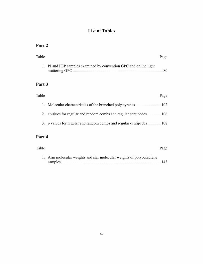
List of Tables
Part 2
Table Page
1. PI and PEP samples examined by convention GPC and online light scattering GPC ...........................................................................................80
Part 3
Table Page
1. Molecular characteristics of the branched polystyrenes ..........................102
2. ε values for regular and random combs and regular centipedes ..............106
3. ρ values for regular and random combs and regular centipedes ..............108
Part 4
Table Page
1. Arm molecular weights and star molecular weights of polybutadiene samples.....................................................................................................143
x
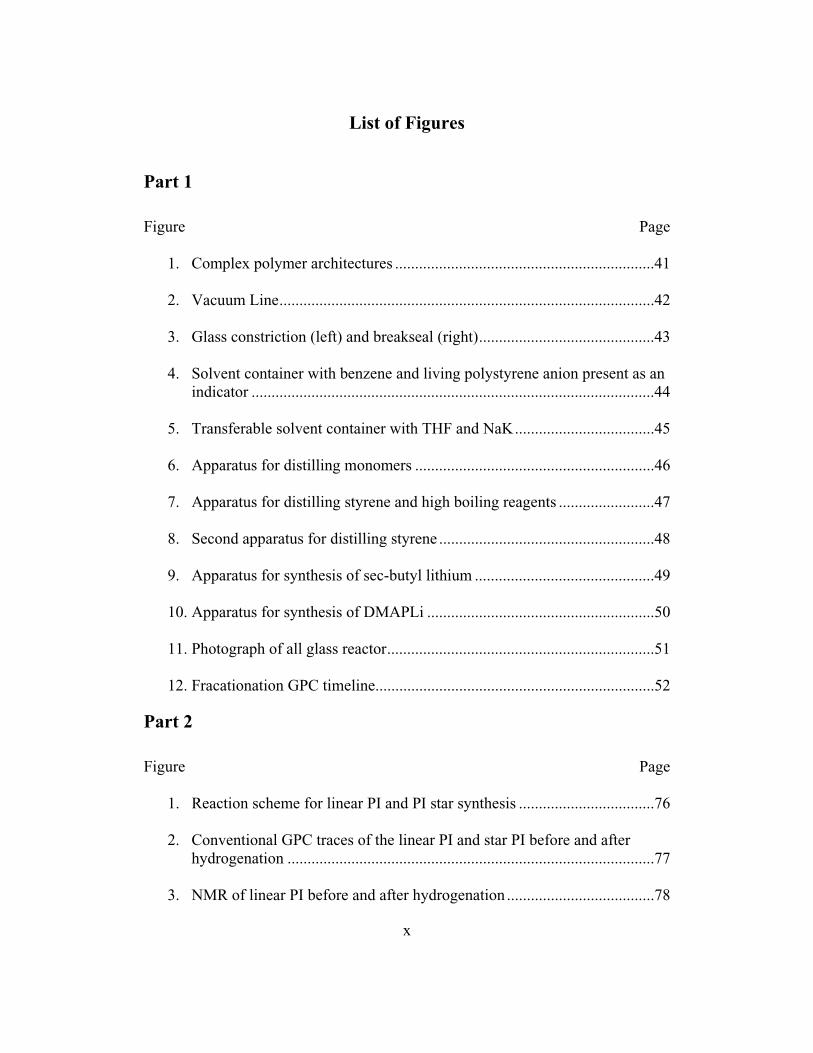
List of Figures
Part 1
Figure Page
1. Complex polymer architectures .................................................................41
2. Vacuum Line..............................................................................................42
3. Glass constriction (left) and breakseal (right)............................................43
4. Solvent container with benzene and living polystyrene anion present as an indicator .....................................................................................................44
5. Transferable solvent container with THF and NaK...................................45
6. Apparatus for distilling monomers ............................................................46
7. Apparatus for distilling styrene and high boiling reagents ........................47
8. Second apparatus for distilling styrene ......................................................48
9. Apparatus for synthesis of sec-butyl lithium .............................................49
10. Apparatus for synthesis of DMAPLi .........................................................50
11. Photograph of all glass reactor...................................................................51
12. Fracationation GPC timeline......................................................................52
Part 2
Figure Page
1. Reaction scheme for linear PI and PI star synthesis ..................................76
2. Conventional GPC traces of the linear PI and star PI before and after hydrogenation ............................................................................................77
3. NMR of linear PI before and after hydrogenation .....................................78

xi
List of Figures (Continued)
4. GPC traces of 6 arm PI before(top) and after(bottom) hydrogenation ......79
Part 3
Figure Page
1. Polystyrene centipede synthesis. Notice that each regularly spaced branch point bears two branches..........................................................................100
2. Polystyrene comb synthesis. Notice that each regularly spaced branch
point bears one branch .............................................................................101
3. Comparison of the dependence of hydrodynamic radius on molecular weight range for different architectures in a good solvent (THF) ...........103
4. Dependence of intrinsic viscosity on molecular weight for different
architectures in a good solvent (THF) .....................................................104
5. Dependence of the hydrodynamic radius on molecular weight for different architectures in a theta solvent (trans-decalin).........................................105
6. Dependence of the Fox-Flory factor Φ on molecular weight ..................107
7. Traditional universal calibration of [η] * M versus retention volume .....109
8. Universal calibration based on log radius of gyration versus retention
volume in the good solvent (THF)...........................................................110
9. Universal calibration based on log hydrodynamic radius versus retention volume in the good solvent (THF)...........................................................111
10. Universal calibration based on log radius of gyration versus retention
volume in the theta solvent (trans-decalin)..............................................112
11. Universal calibration based on log hydrodynamic radius versus retention volume in the theta solvent (trans-decalin)..............................................113

xii
List of Figures (Continued)
Part 4
Figure Page
1. The tin modified POSS cube ...................................................................138
2. Apparatus used to dilute and split down the SnPOSS cube.....................139
3. Linking apparatus used to make the star polymers containing POSS at the core...........................................................................................................140
4. Reaction scheme for the modification of the SnPOSS cube before the
linking process is performed....................................................................141
5. Reaction scheme for the formation of the star material ...........................142
6. GPC of grafting reaction after 45 days ....................................................144
7. GPC of Polybutadiene 8 arm star after 3 days of reacting.......................145
8. GPC of PBD20 and the resulting polymer after fractionation.................146
9. TGA of polybutadiene samples in the presence of air and nitrogen atmosphere ...............................................................................................147

xii
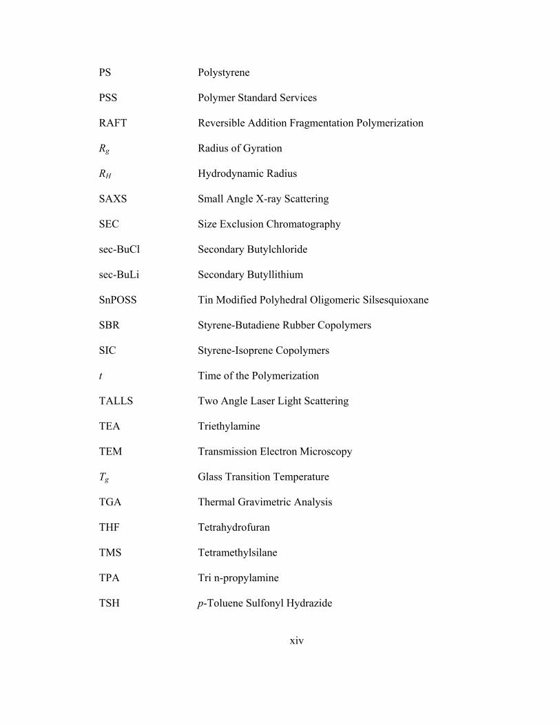
List of Abbreviations
β Flory-Scheraga Mandelkern Parameter
ε Branching Parameter Relation Factor
ρ Ratio of Radius of Gyration to Hydrodynamic Radius
Φ Fox-Flory Factor
[Io] Initial Initiator Concentration
[M] Monomer Concentration During Polymerization
[Mo] Initial Monomer Concentration
[η] Intrinsic Viscosity
[η]M Hydrodynamic Volume
ATRP Atom Transfer Radical Polymerization
BHT Butylated Hydroxytoluene
DLS Dynamic Light Scattering
DMAPCl 3-Dimethylamino-1-Propylchloride
DMAPCL HCl 3-Dimethylamino-1-Propylchloride Hydrochloride
DMAPLi Dimethylaminopropyllithium
dn/dc Refractive Index Increment
DPE Diphenylethylene
DPn Number Average Degree of Polymerization
DSC Differential Scanning Calorimetry
DVB Divinylbenzene
EPDMs Ethylene Propylene Diene Monomers

xiii
g Radius of Gyration Contraction Parameter
g' Intrinsic Viscosity Contraction Parameter
GPC Gel Permeation Chromatography
HPLC High Performance Liquid Chromatography
kobs Observed Rate Constant of Polymerization
kp Rate Constant of the Polymerization
M Molecular Weight
Mn Number Average Molecular Weight
MALLS Multi Angle Laser Light Scattering
MW Molecular Weight
MWD Molecular Weight Distribution
NaK Sodium Potassium Alloy
NMP Nitroxide Mediated Polymerization
NMR Nuclear Magnetic Resonance
PBD Polybutadiene
PDI Polydispersity Index
PE Polyethylene
PEB 1,3 bis(1-phenyl ethenyl)benzene
PEP Poly(ethylene-co-propylene)
PI Polyisoprene
POSS Polyhedral Oligomeric Silsesquioxane
POSSM Polyhedral Oligomeric Silsesquioxane-Styryl Macromonomer
xiv
PS Polystyrene
PSS Polymer Standard Services
RAFT Reversible Addition Fragmentation Polymerization
Rg Radius of Gyration
RH Hydrodynamic Radius
SAXS Small Angle X-ray Scattering
SEC Size Exclusion Chromatography
sec-BuCl Secondary Butylchloride
sec-BuLi Secondary Butyllithium
SnPOSS Tin Modified Polyhedral Oligomeric Silsesquioxane
SBR Styrene-Butadiene Rubber Copolymers
SIC Styrene-Isoprene Copolymers
t Time of the Polymerization
TALLS Two Angle Laser Light Scattering
TEA Triethylamine
TEM Transmission Electron Microscopy
Tg Glass Transition Temperature
TGA Thermal Gravimetric Analysis
THF Tetrahydrofuran
TMS Tetramethylsilane
TPA Tri n-propylamine
TSH p-Toluene Sulfonyl Hydrazide

xv
VR Volume Retention
VII Viscosity Index Improvers
WAXD Wide Angle X-ray Diffraction

1
Part 1
Introduction

2
Polymers are an exceptionally interesting class of chemical compounds. The term
polymer is derived from the Greek words polys and meros which translate into “many
parts.” Polymers can have a wide variety of properties that reflect the molecular weight,
molecular weight distribution, branching, monomer composition, morphology, tacticity,
microstructure, and functionality of the molecules in question. Although polymers can be
synthesized using a range of techniques; they can be classified into some basic categories.
In the 1920’s Carothers classified polymers into two different classes: condensation and
addition polymers. This classification was based on the type of synthesis required to
make the polymer. Condensation polymers require two monomers or one bifunctional
monomer with the removal of a by-product, usually water. Addition polymerizations
represent a large class of polymers based on the addition of one monomer group after
another without the loss of a small molecule.[1] Addition polymerizations can be further
subdivided into free radical polymerization, controlled radical polymerization, cationic
polymerization, and anionic polymerization. Each type of addition polymerization has
advantages and disadvantages, but will limit this discussion to the polymerization method
used for all of the polymers in this thesis – anionic polymerization.
Anionic polymerization offers finest synthetic control with the best homogeneity
during the reaction process. Even though controlled radical polymerization has become a
reliable method to achieve low dispersity polymers this method still does not compare to
anionic polymerization for synthesis of higher molecular weight polymers and complex
architectures. Hawker states, “Until recently, ionic polymerizations (anionic or cationic)
were the only “living” techniques available that efficiently controlled the structure and

3
architecture of vinyl polymers.”[2] The subject of living polymerization not only
includes anionic and cationic polymerization, but Atom Transfer Radical Polymerization
(ATRP), Nitroxide Mediated Polymerization (NMP), and Reversible Addition-
Fragmentation Polymerization (RAFT).
Quirk and Hsieh[3] give nine basic criteria for living polymerizations these are:
1. The polymerization consumes all available monomer, if additional monomer is
added, the additional monomer is also consumed in the reaction.
2. The molecular weight of the polymer, more specifically the number average
molecular weight, increases linearly as a function of monomer conversion.
3. The number of active chain-ends is unvarying during the polymerization and is
independent of monomer concentration.
4. The molecular weight of the polymer can be controlled by controlling the
stoichiometry of the reaction.
⎟⎟⎠
⎞⎜⎜⎝
⎛=
initiatorofmolesmonomerofgramsMWAverageNumber (1)
5. The polymers that are synthesized using living techniques have very low
polydispersities.
6. Block copolymers can be synthesized by simple addition of different monomers
sequentially to form the different polymer blocks.
7. The end functionality of a polymer can be controlled quantitatively by termination
with a desired terminating agent.
8. The rate of propagation of the polymer is a function of time, varying in a linear
manner. If the experimental data is plotted it must fit the equation below.

4
[ ][ ] tkMM
obso =ln
(2)
[M o] = Initial monomer concentration
M = monomer concentration during polymerization
kobs = rate constant of polymerization
t = time of the polymerization
9. The plot of the experimental data will coincide with the linear equation below.
[ ][ ] [ ] tIkDPMI
opno
o −=⎟⎟⎠
⎞⎜⎜⎝
⎛−1ln
(3)
[M o] = initial monomer concentration
[I o] = initial initiator concentration
kp = rate constant of the polymerization
t = time of the polymerization
DPn = number average degree of polymerization
The linearity of a plot of equation 3 demonstrates the absence of chain transfer and chain
termination.[3] In the presence of chain transfer and chain termination, the DPn will not
be a function of time or concentration. Two incidents would occur, for chains were
termination occurs, the DPn would be very low and in the presence of chain transfer the
DPn would increase very quickly. Therefore, the plot of this data using equation 3 would
not be linear.
5
The term “living” polymerization was first used by Szwarc in 1956. Szwarc and
coworkers used a sodium naphthalene initiator to polymerize styrene in two equivalent
steps. This experiment had an approximate yield of 100% after the two additions of
monomer which demonstrated the living nature of the polymer chain ends. To further
prove the living nature of the polymer, a triblock copolymer of the AAA...BBB…AAA
type was synthesized using the same sodium naphthalene initiator. Styrene was
polymerized first and then isoprene was added to the mixture once all of the styrene had
been consumed. The resulting polymer solution could not be precipitated in a selective
solvent for polystyrene or polyisoprene proving the existence of the block copolymer.[4]
Although Szwarc was the first to use the term “living”, Zeigler was the first to report a
mechanism for polymerization of dienes using alkylithium and alkylsodium reagents. He
published these results in 1934.[5-7] The anionic nature of the polymerization was first
discovered by Higginson and coworkers and their experiments with potassium amide
chemistry and initiation of styrene.[8] They discussed the character of the anionic
polymerization as an acid-base system using Lewis acids and base to describe the
polymerization reactions.
The common monomers that are used with anionic initiators must be able to form
a stable anionic species. Monomers that are capable of being polymerized are styrenic,
dienic, and certain cyclic monomers.[3, 9-11] Polymerizations that involve styrenic and
dienic compounds are stabilized by substituents that can delocalize the negative charge.
Ring opening polymerizations of cyclic monomers are only possible when the ring is
subject to ring opening by nucleophilic attack. In general, substituents that promote the
stabilization of the carbanion are: aromatic rings, double bonds, carbonyl, ester, cyano,

6
sulfone groups to name a few. Conversely electrophilic substituents will react with the
living chain end. These include primary and secondary amines, carboxyl, and hydroxyl
groups. Presence of such groups incorporated on the monomer does not prevent the
polymerizations of these monomers; they just pose a challenge in the synthetic approach.
Monomers with electrophilic character must either be modified by protecting groups or
undergo alternate polymerization methods such as specific counter ions, decreased
temperature, or selective initiators. Monomers that have undergone anionic
polymerization are: substituted styrenes[12], vinylpyridines[13], conjugated dienes[14],
acrylates[15], acrylonitriles[16], lactones[17], epoxides[18], and cyclic siloxanes[19] just
to name a few.
Since the 1950s anionic polymerization has been the premier technique for the
synthesis of complex polymer architectures because of the accessibility to countless
different architectures through exceptionally well defined chemistries.[3, 9, 10, 14, 20]
The initiator that is chosen is essential to the way the polymer is synthesized. In order to
achieve the low polydispersities that are achieved with living anionic polymerization
several steps have to take place. The first step is the initiation of monomer by the
initiating species. The second step is the propagation of the active end utilizing the
monomer that is available until all of the monomer is consumed. The last step,
termination, must not occur until the proper terminating agent is added to the system.
The initiation step must be exceptionally fast when compared to the rate of propagation.
This is the mechanism that allows for the low polydispersities seen in living anionic
polymerizations. If the initiation is slow the molecular weight (MW) distribution may be
larger or even bimodal.

7
Today the initiator that is most commonly used is secondary butyllithium. This
particular initiator is useful because of the solubility of the initiator in non-polar organic
solvents such as cyclohexane and benzene. The reactivity of alkyllithium initiators is
linked to the stability of the anion and also to the degree of aggregation of the
alkyllithium initiator in solution. In general the more substituted the carbon of the
carbanion the more reactive the initiator is. There are exceptions to this rule. For
example the t-butyl lithium anion reacts slower than n-butyllithium anion when used in
conjunction with styrene monomer.[10] This conclusion is based not only on the
reactivity of the initiator, but is also linked to the steric hindrance of the initiator coupled
with aggregation of the initiator species and the initiator species where a unit of
polystyrene has already been polymerized and formed a living polystyryllithium chain
ends. The reactivity of the carbanion is not only a function of the anion, but also the
amount of carbanion aggregate that is formed in solution, and the steric characteristics of
the initiating species. In solution s-butyllithium can form carbanion aggregates that have
trifunctional, tetrafunctional, and hexafunctional species. The amount of aggregation can
be controlled by selection of the initiator species, solvent, and additives. In general
initiators follow the general reaction rate hierarchy:
For dienes: Menthyllithium > s-butyllithium > i-propyllithium > t-butyllithium >
n-butyllithum and ethyllithium.
For styrene: Menthyllithium > s-butyllithium > i-propyllithium > n-butyllithum
and ethyllithium > t-butyllithium.[10]
The initiators mentioned earlier are all monofunctional initiators that only afford
one living chain end. Other initiators have been studied that have difunctional,

8
trifunctional, and multifunctional moieties. Difunctional initiators such as sodium
naphthalene complex[4] or sec-butyllithium in conjunction with 1,3 bis(1-phenyl
ethenyl)benzene (PEB)[21] provide living polymerizations with two living chain ends.
Trifunctional initiators have been synthesized, but the solubility of the anion and 100%
initiator efficiency become an issue[3]. Multifunctional initiators have been synthesized
from divinylbenzene (DVB), but solubility also becomes an issue. DVB is more valuable
as a linking agent in star molecules[22, 23]. Initiators with functional groups can also be
used to perform anionic polymerizations. Protected amine and alcohol initiators have
been synthesized and in some cases are commercially available from companies like
FMC Lithium Corporation. Functional initiators such as dimethylaminopropyllithium are
discussed later in greater detail.
As mentioned earlier anionic synthesis offers the finest synthetic control when
synthesizing polymers, not only based on composition, but architecture as well. Anionic
synthesis provides the ability to make a variety of polymer architectures. The types of
architectures that can me synthesized are: star, comb, centipede, barbwire, cyclic, and
hyperbranched varieties.[14] Each type of architecture can be accessed through a variety
of strategies. An example of the some the architectures can be seen in Figure 1. All
figures will be at the end of this particular part in the appendix.
A star polymer is a polymer with a central graft point and the polymer arms
radiate from the central graft point. They can have as little as three arms and as many as
128 or larger. Comb polymers are polymers that have long polymer chains grafted to the
backbone in a random or regular spacing. In a comb polymer there is only one graft per
site on the polymer back bone. As the number of polymer grafts increases at a particular

9
point the centipede type polymer is created, this polymer has two polymer chains
attached at a single graft point along the back bone of the primary polymer. If the
number of grafts was increased even further for example 6 polymer chain grafts per graft
point along the polymer backbone this would be described as barbed wire type
architecture. A hyperbranched polymer would have a large amount of branching upon
branching if the spacing is regular and ordered these types of polymers can be referred to
as dendrimers. Cyclic polymers have no chain ends and therefore have unique solution
properties as is the case with each architecture mentioned above.
Star polymers can be synthesized through a multifunctional initiator or coupled
through a linking agent introduced after the arm of the star has been synthesized. As
mentioned earlier several problems arise from multifunctional initiators including
aggregation and solubility difficulties. Coupling reactions tend to control the synthetic
approach of star polymers because of the ease of characterization of the arm material.
Star polymers composed of differing arm composition, such as block copolymers, as well
as polymers of different chemical composition have been synthesized. One of the most
difficult to synthesize star polymers is the miktoarm star polymer. They are composed of
stars where each arm consists of a chemically different polymer. The term mikto is the
Greek word meaning mixed.[24] Chlorosilanes are common linking agents used in the
formation of stars. A large number of chlorosilanes are available through commercial
vendors. Stars with 3, 4, 6, and up to 18 arms have been synthesized through this
method.
Combs, centipedes, and barbwires are types of graft copolymers and can be
synthesized using anionic techniques. A variety of structures are accessible as is the case

10
with star polymers. There are three different synthetic approaches to producing a graft
copolymer. The three methods are “grafting onto”, “grafting from”, and “grafting
through”.
The “grafting onto” method involves reacting all of the pieces of the
macromolecule separately. For example, pieces of the backbone and the arm material are
prepared and characterized separately, then combined through a coupling agent in a ratio
that yields a comb polymer. This method has the distinct advantage that every part of the
final polymer can be characterized individually before assembly into the larger
architecture.
The “grafting onto” polymerization was performed in our lab by David Uhrig[25].
In his work, he grafted polystyrene onto a polyisoprene backbone. The first step of the
synthesis was to polymerize the arm portions of the graft. The styrene was polymerized
and then coupled with a trichlorosilane in a slight excess. The polystyrl anion is limited
to two additions to the trichlorosilane because of the steric hindrance of the bulky phenyl
group. The backbone was then polymerized using the difunctional initiator PEB and s-
butyllithium to synthesize the polyisoprene portion of the polymer. The living
polyisoprene is then coupled with the polystrylsilane molecule to generate the graft comb
material seen in Figure 1. This method was used to construct comb and centipede type
polymers.[26]
The “grafting from” method entails incorporating a reactive group in the polymer
backbone. This reactive site is usually protected and activated after the initial
polymerization of the backbone. Afterwards a polymerization is initiated from the
modified sites on the backbone. This results in the arms of the comb growing from the
11
backbone. Characterization of the arm material is a difficult task and usually involves
some type of degradation of the backbone to isolate the arm material.[14]
The third method, “grafting through”, involves the synthesis of a macromonomer
that has a terminal polymerizable group. This macromonomer is then polymerized either
with or without another monomer to generate the backbone of the comb polymer. The
spacing of the arm material can be modified by sequential addition of monomer followed
by the addition of macromonomer and so on. This type of polymerization is difficult to
control and the polymers produced can vary substantially in composition.[14]
Recent advances in anionic polymerizations provide the unique ability to
manipulate polymers in forms that are not accessible through other chemistries. A large
challenge is the characterization of these complex molecules. The synthesis of model
polymers permits characterization methods to be developed and tested. The purpose of
this work is to synthesize complex architectures and explore a variety of characterization
techniques of these molecules.
Experimental
Anionic polymerization requires exceptionally rigorous conditions and a
significant amount of patience. These polymerizations are analogous to a high risk - high
yield investment in the business world. Linking reactions may take weeks or months to
perform, but the reward for a model synthetic polymer is the “high yield”. In the case of
anionic polymerization the “high risks” include: solvent purity, monomer purity, initiator
efficiency, broken break seals, mercury diffusion pumps, and other pitfalls too numerous

12
to discuss. The rewards of anionic polymerization are very low polydispersities and well
defined structures.
Vacuum Line
All of the polymer synthesis that described in this work was performed using high
vacuum techniques combined with the construction of unique and specifically designed
glass apparatus. The vacuum line was constructed of Pyrex glass tubing mounted on a
steel frame. The line was utilized a mercury diffusion pump joined by two opposing
glass vacuum traps. These opposing vacuum traps were cooled by liquid nitrogen and
served different functions. The first trap is to prevent organic solvents and molecules
from entering the mercury diffusion pump and eventually the rough vacuum pump. The
later vacuum trap was put in place to prevent the movement of mercury to the rough
vacuum pump. The rough pump used in this particular configuration was a Welch model
#1402 duo seal pump. To maintain the integrity of the vacuum pump it is recommended
that the pump oil be changed once a month to prevent pump damage from organic
compounds that are not trapped by the liquid nitrogen cold traps. If the experimentalist is
particularly carefully with the upkeep of the vacuum line, the pump oil can be used up to
two or three months, but more is not recommended. Through our experience as a lab, we
have found the best stopcocks to use for these types of vacuum systems are J. Young
Teflon stopcocks. In particular we have used the in-line tap type stopcock with a Teflon
piston and o-ring seals. A representative drawing of the vacuum line can be seen in
Figure 2. This vacuum line was equipped with an additional drying attachment to allow
the drying of polymer samples for extended periods of time. The main attachments of the

13
vacuum line were ground glass joints obtained from Ace Glass or Kontes Glass
Company. All ground glass seals were joined using high vacuum silicon grease from
Dow Corning. Some of the attachments to the vacuum line were left as straight Pyrex
tubing to allow for apparatuses to be attached more securely by glass blowing and thus
avoiding a ground glass seal and silicon grease.
This vacuum line’s pressure was tested with an ion gauge attached to a ground
glass joint. The ion gauge controller used to test the vacuum was a Granville Phillips
model # Series 270 ion gauge controller. The vacuum line was able to obtain vacuum
pressures in the range of 10-5 Torr with the mercury diffusion pump. The vacuum line
was also tested with the use of a Tesla coil to verify the vacuum pressure. It was noted
that the Tesla coil became quiet in the 10-4 Torr pressure range. The test performed with
the Tesla coil involved contact of the Tesla coil with the vacuum line. When a proper
vacuum was obtained, there was no discernable difference in noise from the coil when
comparing contact and non-contact with the vacuum. If a proper vacuum was not
achieved the Tesla coil was notably louder when in contact with the vacuum line.
Sometimes a noticeable glow was present inside the vacuum line when a poor vacuum
was present.
Apparatus
All apparatus were constructed from Pyrex tubing and Pyrex round bottom flasks.
All of the glassware was constructed manually and annealed in a furnace at 5650C to
ensure that stresses created by glass blowing were relieved, thereby making the glass
more durable. Two main glass connections that must be mastered when using glass
blowing techniques to perform anionic polymerization are seen in Figure 3. The picture

14
on the left is a photograph of a glass constriction. The glass constriction provides a
junction in the glass which can be flame sealed when under vacuum. This allows for
parts of apparatuses to be removed, glass ampoules to be sealed, and removal of
apparatuses from the main vacuum line once a proper vacuum has been achieved. The
glass constriction is made simply by rotating glass in a hot flame and allowing the glass
to condense itself into a smaller opening with thicker glass tubing around the area. The
glass is held in a manner so that no apparent tension is on the glass tubing. As the
heating increases and the glass turns molten, the glass will slowly pull itself together as
the glass flows toward the middle of the flame. This particular description is over
simplified, but for the purposes of this discussion sufficient. Proper techniques require
high-quality teaching and ample practice.
The picture on the right is a photograph of a glass break seal. This particular
glass tool is useful in the fact that it allows different reagents to be added to a reaction
vessel without exposing them to an outside contaminant. This is used in glass ampoules,
to allow the introduction of other polymers into a reaction system, and to allow the
reintroduction of a system back to the vacuum line. This tool is also made from Pyrex
tubing and a proper explanation is beyond the scope of this discussion. Again, the best
instruction is from an experienced glass blower trained in the classic anionic
polymerization technique or other experimental systems.
All apparatus are constructed from some combination of these two tools in
conjunction with round bottom flasks, tubing, and ground glass joints. Once an apparatus
has been assembled the entire system must be checked for pinholes with the Tesla coil. If
a pin hole is present an arc from the Tesla coil will reveal the source of the vacuum leak.

15
Careful attention must be used when performing this because using too strong of a
current or leaving the Tesla coil in one place for an extended period of time, can create a
pinhole.
Further descriptions of the types of apparatuses used are described in the
purification of the reagents along with corresponding figures in the appendix.
Purification of Reagents
Benzene
Reagent grade benzene was obtained from Fisher Scientific and was allowed to stir over
concentrated sulfuric acid for a period of no less than 1 week. Additional benzene can be
set aside over sulfuric acid and no stirring is necessary if sufficient time is allowed for the
impurities in the benzene to react (usually longer than 1 month). The benzene is
subsequently decanted into a round bottom flask and calcium hydride is added to the
flask to remove any moisture left over from the treatment with the sulfuric acid. The
mixture is attached to the vacuum line and frozen with liquid nitrogen. This mixture is
degassed once and then allowed to thaw. The mixture is then stirred overnight to allow
the calcium hydride to react. The system is then degassed the following day undergoing
three freeze thaw cycles. The benzene is then distilled into a calibrated cylinder that is
attached to the vacuum line containing a mixture of n-butyllithium and styrene. Less
than 1 ml of styrene is used directly (Sigma Aldrich, unpurified). Approximately 10 ml
of 1.6 M n-butyllithium in hexanes is added (Sigma Aldrich). (Through my personal
experience Sigma Aldrich seems to have the best quality butyllithium.) The hexane is
previously removed before the distillation of the benzene into the cylinder. The resulting

16
solution is degassed three times and allowed to stir overnight. In time an orange
persistent color will develop. This color is due to the presence of a living polystyrene
anion, the presence of this color ensures that the benzene is satisfactorily pure for anionic
polymerization. The color is demonstrated in Figure 4. The color provides a clear
indication as to whether the benzene is sufficiently “healthy”, if the color fades or ceases
to exist then the benzene is contaminated and needs to be re-purified.
Hexanes
Reagent grade hexanes were obtained from Fisher Scientific and were purified in
a manner similar to benzene. The only substantial difference in the purification of the
reagent is the addition of styrene. The smallest amount of styrene should be added, no
more than a couple of drops. This is due to the insolubility of the high molecular weight
polystyrene anion in hexanes. If very small oligomeric chains exist the anion is able to
be kept in solution and a similar orange color persists indicating if the solvent is
sufficiently pure or not.
Tetrahydrofuran
The THF was initially dried over CaH2 which is degassed three times and allowed
to stir over night. The THF was then distilled over sodium metal and allowed to stir for 6
hours. The solution is then distilled to a cylinder that contains sodium potassium (NaK)
alloy. The alloy is made from 3 to 1 mixture of potassium to sodium which is a liquid at
room temperature. Synthesis of the alloy begins by cleaning the sodium and potassium
under a solution of hexanes to prevent further oxidation of the metals. The metal oxides
are scraped off the metals using forceps and a spatula and then cut into small pieces. The
metals are then transferred to a clean container with clean hexanes and then the metal and
17
hexanes are transferred to the cylinder into which the THF will be distilled. The cylinder
also contains a magnet encased in glass as the alloy is very reactive and will eventually
destroy Teflon coated magnets. The container is pumped down on the vacuum line to
remove all of the hexanes and then the cylinder was slowly heated by a very small flame
from a glass blowing torch, until the sodium just begins to melt. Once the sodium begins
to melt the magnet was manipulated to allow the sodium and potassium to mix and form
the alloy. The THF is then distilled from the sodium chunks into the cylinder with NaK,
and the mixture undergoes 3 freeze/thaw degas cycle, and was allowed to stir until a blue
color was observed. It is useful to note that during the freeze/thaw cycles the glass
encased magnet must be moved above the THF solution level, because during the
freezing process the magnet is very susceptible to cracking and breaking. The blue color
is indicative of the purity of this solvent. The blue color and the transfer apparatus are
shown in Figure 5.
Isoprene
Isoprene was obtained from Sigma Aldrich and was purified in three steps. The
isoprene is first poured into a round bottom flask containing calcium hydride and
attached to the vacuum line. The mixture is degassed once and allowed to stir overnight.
The mixture was then degassed by 3 freeze/thaw cycles the following day. The isoprene
was then distilled to another round bottom flask containing sodium chunks and allowed
to stir at 0oC for one hour. The isoprene was then distilled to another round bottom flask
containing n-butyllithium and allowed to stir for 30 minutes at 0oC and a slight yellow
color will develop depending on the amount of butyllithium that is used. The isoprene
was then distilled to ampoules that had been graduated to specific amounts and was

18
stored in the freezer for later use. If sodium is not available the second purification can
be substituted with another treatment with butyllithium, once more only for 30 minutes at
0oC. Isoprene is the simplest monomer to purify because it has a low boiling point yet is
a liquid at room temperature.
Butadiene
1,3-Butadiene was obtained from Sigma Aldrich and was purified in the same
three steps as isoprene. Butadiene is a difficult monomer to use because the monomer is
a gas at room temperature. Extreme caution must be used when purifying this monomer.
The monomer comes in a gas cylinder from Sigma Aldrich, a regulator must be used
when using this monomer. The regulator should only be used with this monomer because
some of the monomer will remain in the regulator after every use. The gas was first
condensed into a round bottom flask in a dry ice/isopropanol bath. Once enough
monomer has been collected calcium hydride was added to the flask. If the calcium
hydride is added first the incoming gas can spray the calcium hydride everywhere. The
flask is immediately transferred to the vacuum line and degassed. The flask was
continuously chilled at -78oC and allowed to stir for one hour. The butadiene is then
distilled to another flask containing sodium pieces and degassed. The flask with the
sodium pieces and butadiene was allowed to warm to -10oC and stirred for 30 minutes.
This mixture is cooled by an ice/water slurry with a large amount of sodium chloride
added to bring the temperature down to the desired -10oC. This temperature is very
important because of the low boiling point of the monomer which is -4.5oC. The
butadiene must be kept cooler than this temperature or the flask can explode. The flask
in all the cases for butadiene is never clamped to the vacuum line just in case the

19
temperature does rise above the boiling point the flask will blow off the line instead of
exploding. The butadiene is then distilled to another flask with n-butyllithium that was
attached to the vacuum line and all of the hexanes removed. The butadiene is degassed
and was allowed to stir at -10oC for 30 minutes. One final degas of the material was
performed before the monomer was distilled to pre-measured ampoules. The density of
the monomer at -78oC is 0.74 g/ml. Once the desired amount of butadiene has been
distilled to the ampoule another material is distilled the ampoule usually benzene or
hexanes. In my experiments I used hexanes because this solvent does not freeze near
0oC. The hexanes were distilled to amount that was twice the volume of the butadiene in
the ampoule. This prevents the ampoules from breaking at room temperature; the
hexanes sufficiently lower the vapor pressure of the butadiene which allows the break
seals to maintain their integrity. Isoprene and butadiene were distilled using an apparatus
shown in Figure 6.
Styrene
Reagent grade styrene was obtained from Sigma Aldrich and underwent a two
step purification process. The styrene was first added to the apparatus shown in Figure 7.
A short path distillation apparatus is necessary because of the high boiling point of the
monomer. The first purification process is performed over calcium hydride. The styrene
was added and the system was degassed. The constriction where the styrene was added
was heat sealed and the styrene was allowed to stir overnight. The system was degassed
by three freeze/thaw cycles before the distillation to the ampoules was started. Heavy
wall tubing is used instead of the constriction to the ampoule because the heavy wall
tubing allows for easier distillation then a constriction allows due to its larger diameter.

20
Once an ampoule was taken from the first distillation process it was attached to
the apparatus seen in Figure 8. Dibutylmagnesium was added to the apparatus through a
rubber septum located on the round bottom flask. The constriction was washed and then
heat sealed. The dibutylmagnesium was obtained from Sigma Aldrich in 1.0 M heptane
solution. The heptane was removed by vacuum and then system was isolated and the pre-
purified styrene was added to the flask through the break seal. The addition of the
styrene to the dibutylmagnesium causes a faint yellow color to develop; this solution was
allowed to stir for two hours. Dibutylmagnesium is used to purify the styrene because n-
butyllithium reacts too fast with the styrene monomer. The styrene was distilled to the
ampoules and degassed before heat sealing the heavy wall tubing. The ampoules were
stored in the freezer until the day they were needed. It is necessary with styrene
ampoules to check the viscosity of the ampoule before use because styrene is known to
undergo spontaneous polymerization in the ampoule.
Divinylbenzene
Divinylbenzene was also purchased from Sigma Aldrich as a 80% technical grade
mixture of isomers. The purification of divinylbenzene (DVB) was in the same manner
as styrene monomer was purified. The only difference in the purification of the DVB
monomer was because the boiling point is higher than that of styrene, distillation can be a
challenge. The boiling point of DVB is 195oC; therefore the distillation process is
usually assisted with a heat gun or a very soft flame from the glass blowing torch. Also
because the DVB is a very viscous monomer the ampoule is usually diluted with benzene
to assist in the addition of the monomer to a reaction and to reduce the tendency for self
polymerization. The ampoules are stored in the freezer until use and since the monomer

21
is usually added after a day of polymerization it is necessary to keep the ampoule cooled
until the monomer is going to be utilized.
Chlorosilanes
Methyltrichlorosilane, Dichlorodimethylsilane were obtained from Sigma Aldrich
and purified using calcium hydride. The chlorosilanes were ordered in 100 ml or 100 g
size bottles and used only once to ensure the proper silane was used. An entire bottle of
the silane were transferred to a round bottom flask and attached to the vacuum line. The
silane was degassed once by a freeze/thaw cycle and allowed to stir over night. The
silane was degassed by three subsequent freeze/thaw cycles before distillation began.
The silane was distilled by a fractional distillation. The first third of the material was
distilled to another round bottom flask and discarded. The middle third was collected in
an ampoule and sealed for use as a linking agent and the remaining third was also
discarded. The silanes were used neat in some cases in other cases they were diluted with
purified hexanes to the desired concentration. If dilution is necessary it is recommended
that the glass apparatus is pretreated by silanation with chlorotrimethylsilane to ensure
that side reactions do not occur with silicon hydroxide present on the glass surface. This
is performed simply by distilling in a small amount of the chlorotrimethylsilane into the
apparatus being used and using a rag dipped in liquid nitrogen to condense the
chlorosilane on the glass in the desired locations. Once the glass has been washed the
excess chlorosilane is removed by distillation and allowed to dry on the vacuum line until
the apparatus is used.

22
1,2-bis(trichlorosilyl)hexane
1,2-bis(trichlorosilyl)hexane chlorosilane was purified in the same manner as the
other two chlorosilanes, but this particular reagent also requires the use of short path
distillation apparatus. Also the assistance of a soft flame or heat gun is also used to assist
the distillation process. The reagent has a very high boiling point of 281oC which makes
the distillation a challenge. It is also recommended that when diluting this reagent a
silanation treatment of the glass is necessary.
Methanol
Reagent grade methanol was obtained from Fisher Scientific. The methanol is
utilized as a terminating agent to the anionic polymerization process. The only
purification that is necessary is that the methanol is thoroughly degassed by three
freeze/thaw cycles on the vacuum line. A small amount of methanol is then distilled to
ampoules usually less than 1 mL is all that is necessary for the termination of a polymer
because the amount of living anions is so minute.
Sec-butyllithium
Sec-butyllithium (sec-BuLi) was synthesized from sec-butylchloride (sec-BuCl)
and lithium metal. Lithium metal was used with at least 6 times excess the molar amount
necessary for the reaction.
sec-BuCl + 6 Li → sec-BuLi + excess Li + LiCl
The sec-butylchloride was purified by drying the reagent over calcium hydride on the
vacuum line over night. The sec-BuCl was degassed three times by three freeze/thaw
cycles. The purified sec-BuCl was then ampoulized in an apparatus similar to those for
23
butadiene and isoprene. The ampoule of purified sec-BuCl is then attached to an
apparatus seen in Figure 9. The sec-BuCl was reacted with lithium granules that were
measured in an inert atmosphere dry box and then transferred to the apparatus under a
nitrogen blanket. The entire system was attached to the vacuum line and flame dried.
The system was injected with a purging reagent usually n-butyllithium obtained from
Sigma Aldrich. Sec-BuCl may be used, and will save time during the washing process.
If sec-BuCl is used the washing of the apparatus with the purging solution can be
shortened, because a small amount of residual sec-BuCl will not affect the reaction
outcome. If n-butyllithium is used, washing the reactor is very important to the purity of
the desired product. Once the purging agent has been injected into the apparatus the
constriction it was introduced through is washed and heat sealed. Washing was
performed by using a small piece of cloth and dipping it into liquid nitrogen and then
applying the rag above the desired location to be washed. This causes the solvent in the
system to condense and wash over the desired area. A desired amount of hexanes was
then distilled into the apparatus. The hexanes were purified as mentioned earlier. The
entire apparatus was degassed and then heat sealed from the vacuum line. The entire
apparatus was rinsed with the hexane and purge reagent making sure that all the glass
comes in contact with the solution. The heavy wall glass where the lithium granules were
introduced was washed thoroughly then heat sealed to remove the ground glass joint.
The entire apparatus was orientated so the purge section was at the bottom and rest of the
apparatus was upright. Then the purge section was heated with lukewarm water to
promote the condensation of hexanes throughout the apparatus. The system was allowed
to reflux for 2 hours and then washed with the cloth method all over the apparatus ten

24
times. Once the washing is finished the purge section is cooled in a bath of ice water.
The apparatus was turned horizontally and the round bottom flask opposite the purge
section is covered in ice. This manipulation of the entire apparatus is performed in such a
manor that purge solution stays within the purge section. At this point the hexane will
began to distill to the reaction vessel while leaving the excess butyllithium and impurities
in the purge section. The purge section may be bathed in water to facilitate the
distillation but only with water that is room temperature. Water no warmer than room
temperature is necessary to avoid bumping of the liquid, if bumping occurs the washing
process may need to be repeated. Once all of the hexanes has distilled the purge section
was removed by heat sealing the constriction between it and the reactor vessel.
The reactor is then repositioned so the lower flask is the flask containing the sec-
butylchloride. The flask is bathed in an ice water bath and the sec-butylchloride ampoule
was fractured with the breaker. This allowed to the sec-butylchloride to distill slowly
into the hexanes and lithium granule solution. This method prevents Wurtz coupling
which may occur as a side reaction. The reaction was left stirring over night at 0 oC. The
following day the solution was filtered through the glass filter frit and collected in
ampoules. A sample of the initiator was taken and immediately, opened and mixed with
deionized water. This solution was then titrated to determine a rough calculation of the
concentration of sec-BuLi formed in the reaction. This titration is only a rough method
for determination of the concentration of the initiator. A more accurate determination of
the concentration was conducted later performing a standardization polymerization using
a known amount of styrene and determination of the molecular weight that was formed.
The number of moles initiator can then be calculated from the equation.

25
Grams of Monomer / Moles of Initiator = Molecular Weight
From this calculation the concentration of the initiator can be determined. The
ampoules were stored in the freezer until further use or need for further dilution.
Dimethylaminopropyllithium
Dimethylaminopropyllithium (DMAPLi) was synthesized in a manner similar to
that of sec-BuLi. DMAPLi is synthesized from 3-dimethylamino-1-propyl chloride
hydrochloride (DMAPCl HCl) which is reacted with lithium metal. A large excess of
lithium is also used in reaction, at least a 6 times excess.
DMAPCl + 6 Li → DMAPLi + excess Li +LiCl
The DMAPCl HCl was purchased from Sigma Aldrich 98% pure. The DMAPCl HCl
was dissolved in deionized water and titrated with a sodium bicarbonate mixture until the
solution was slightly basic. The 3-dimethylamino-1-propyl chloride (DMAPCl) product
was extracted with 3 equivalents of hexanes with a separatory funnel. The resulting
organic layer was rotary evaporated until all of the hexanes were removed. The resulting
liquid was transferred to the vacuum line and mixed with calcium hydride in a short path
distillation apparatus similar to the one employed in the first purification process of
styrene. The solution was degassed once and allowed to stir over night. The following
day the solution was degassed three times through three freeze/thaw cycles and then
distilled to the ampoules.
The synthesis of the DMAPLi was performed in an apparatus in Figure 10. This
reaction was performed in the same manner as sec-BuCl until the last step of collection of
the ampoules. During the reaction process of DMAPCl with lithium small white crystals
become visible in the solution. The crystals that are formed are the DMAPLi which are

26
not soluble in hexanes. The DMAPCl undergoes some Wurtz coupling during the
reaction process and this material needs to be removed due to the polar nature of the
compound and the affect this can have on the microstructure of dienes during the
polymerization process. Therefore the hexanes are filtered through the glass frit and
collected in the extra round bottom flask attached to the apparatus. During this time the
remaining material may be washed using the cloth method to ensure that most of the
coupled product is removed. Once this was completed the flask was removed by heat
sealing the constriction that connected it to the apparatus.
The reaction vessel was reintroduced to the vacuum line via the break-seal located
on the opposite end of the vessel, and purified benzene was distilled into the system. The
benzene dissolved the crystals and the resulting solution was filtered through the frit and
collected in the provided ampoules. A small amount was surrendered to allow for a
titration. A note, the resulting mixture requires twice the amount of acid to bring the
titration to the endpoint due to the hydrochloride salt that is formed in addition to the
lithium hydroxide that was formed. Also a polystyrene polymer was also synthesized
using the initiator to calculate an accurate concentration of the DMAPLi. The ampoules
were stored in the freezer until use. When storing ampoules containing benzene as the
dilution agent an added precaution is necessary. Since benzene freezes at 60C most of the
solution should be moved away from the constriction to avoid breaking the seal while the
benzene freezes. Although this phenomenon does not occur every time I have fallen
victim to this action during my experience of storing this initiator.

27
Polymerizations
The polymerization procedure described here is useful for styrene, butadiene, and
isoprene. The basic polymerization reactor is seen in Figure 11. Assembly of the reactor
may take place a couple of days in advance, but addition of the initiator and monomer
ampoules should be conducted on the day of the polymerization to avoid degradation of
the initiator and monomer. Once the reactor was completely assembled the reactor was
placed on the vacuum line and thoroughly flame dried. The reactor was then charged
with n-butyllithium as a purging agent. The hexanes from the n-butyllithium were
removed and the constriction was heat sealed. Purified benzene was then distilled into
the apparatus to bring the concentration of the monomer to 10% solution. This
concentration is useful for polymers with MW’s lower than 100,000 g/mol, for MW’s
greater than 100,000 g/mol, especially the diene monomers, 5% weight solution or lower
is recommended. The concentration of the polymerization is important because viscosity
can have a strong affect on the polydispersity of the polymer being prepared. Once the
solvent was completely distilled, the solvent was frozen with liquid nitrogen and
degassed carefully, then heat-sealed from the vacuum line. At this point this is the
reactor depicted in Figure 11.
The solution of n-butyllithium and benzene was allowed to thaw in a cold water
bath until the solution reached room temperature and the heat sealed constriction was
cool to the touch. The entire apparatus was washed with the solution through
manipulation of the reactor until every part of the glass had contact with the solution.
Careful attention to move the glass breakers at this point is necessary to ensure that the
glass between the breakers and the wall of the reactor are also cleaned. The solution was

28
then collected to the purge section of the apparatus. The purge section was then
submerged in a warm water bath and the reactor was washed with a rag dipped in liquid
nitrogen. This step is necessary to ensure that all of the n-butyllithium was recovered to
the purge section. Any excess n-butyllithium can initiate the polymerization, and since
the n-butyllithium reacts slower than sec-butyllithium the polydispersities of the polymer
being synthesized can be altered. Also the desired MW that is being targeted will be
changed. During the washing process the purge section is periodically dipped in a ice
water bath to condense all of the solution back to the purge section, this is usually done
every 2 to 3 wash cycles. The entire apparatus was washed a total of ten times with the
rag dipped in liquid nitrogen. After the last wash the purge section was cooled again to
ensure that all of the solution was condensed back to the purge section.
The entire reactor was then manipulated in a manner that the apparatus was in a
horizontal orientation, but the solution was maintained in the purge section and as to not
contaminate the cleaned reactor. At this point the round bottom flask of the reaction
apparatus was surrounded with ice and the purge section was submerged in room
temperature water. Room temperature water is necessary because warm water will cause
bumping inside the reactor which could cause the solution to bump into the cleaned
reactor. If this occurs the reactor must undergo the washing step listed previously. A
glass encased magnet may be employed before the reaction vessel is sealed to facilitate
the distillation, but this step is left to the discernment of the experimentalist.
Once the distillation was completed the constriction was flame sealed between the
reactor and the purge section leaving a pristine reactor for the anionic polymerization to
proceed. At this point the heat seal constriction was allowed to come to room

29
temperature and then the initiator break seal was broken and the initiator solution was
thoroughly mixed with benzene. The monomer break seal was then compromised and a
thorough mixing of the initiator, benzene, and monomer was conducted by agitation of
the reactor. (When using butadiene it is necessary to cool the ampoule with a rag dipped
in liquid nitrogen before fracturing the break seal. The vapor pressure inside this
ampoule is greater than that inside the reactor which can cause the breaker to be forced
into the constriction above the ampoule causing the glass to crack or break compromising
the entire reactor. Cooling the ampoule before fracture prevents the large difference in
pressures and ensures a much gentler addition of the monomer to the vessel.) At this
point the reactor was manipulated so that all of the solution was collected in the large
flask of the reactor. It is important that all of the solution be collected to one area of the
reactor or differing MW’s can be obtained because of differing concentration regimes
located within the reactor. The reactor was then left overnight to allow the
polymerization to occur.
Once the polymerization occurs, the living polymer solution can be kept for years
in this state as long as the glass apparatus is not compromised. At this point the solution
can be transferred to a transfer vessel that can be connected to another apparatus, or the
polymer can be terminated with the methanol ampoule. If the polymer is terminated, the
solution is precipitated into a beaker with methanol, usually ten times the volume of the
reaction solution. The methanol is also treated with small amount of butylated hydroxy
toluene (BHT) to prevent oxidation of the polymers.

30
Fractionation
Polymer fractionation is complex and difficult to express. Simply described it is
the separation of a disperse polymer sample into narrow fractions that are representative
of the entire MW distribution. “Carrying out the precipitation process successfully
requires a certain degree of experience and is not free of arbitrariness.”[27] Every
fractionation that was carried out utilized a “downward” or “upward” fractionation or
some combination of the two in multiple steps. In the case of the polymers presented in
this dissertation, all fractionations where conducted using a solvent system of toluene and
methanol to perform the molecular weight separations. This solvent pair is useful in the
fractionation of isoprene, butadiene, and styrene polymers or combinations thereof.
The polymer that is in need of fractionation is dissolved in a “good” solvent at a
low concentration, usually not to exceed 5% by weight. A “good” solvent refers to a
solvent that is thermodynamically favorable for the polymer in this case toluene. This
represents a situation in which a polymer is in a swollen or in a dissolved state. During
the dissolving process a small amount of antioxidant is added to prevent degradation of
the polymer, in all of the fractionations performed BHT was added in an amount of 1.0
wt% of the polymer being dissolved. For example 10 grams of polyisoprene polymer
was dissolved in 1000 mL of toluene in a 2 L Erlenmeyer flask. This mixture was
allowed to stir until the entire polymer was dissolved. The amount of time is dependent
on the MW and may require the system to stir overnight or longer. Once the polymer
was completely dissolved, methanol, a thermodynamically “bad” solvent, was slowly
added to the solution while stirring until the solution became turbid. Sufficient time
should be allowed for the turbidity to dissipate before proceeding to the next step. The

31
solution will begin to take on a slight blue color when the critical turbid point, also
known as the cloud point, is imminent. The slight fluorescent blue taken on by the
solution is due to the aggregation of the polymer in the thermodynamically stressed
solution. Once the cloud point of the solution has been reached the solution is slowly
heated to 350C. During the heating process another addition of methanol is added to the
solution, the amount of the aliquot is dependent on the amount of polymer present and the
experience of the individual. In most cases, 10 ml to 25 ml of methanol was added to the
solution. At 350C the solution should be clear and colorless. If too much of the “bad”
solvent was added the solution may not turn clear when heated to 350C. If this point may
not be reached, if this occurs toluene may be added to bring the solution back to clear and
colorless, this must be done very slowly as the addition of too much toluene will prevent
the phase separation from occurring.
To continue the fractionation process a separatory funnel is used. The funnel is
heated either by a heat gun or flame from a glass blowing torch. The heating is gentle in
nature and the desired final temperature is 350C or slightly above, it is important to not to
overheat the funnel or the solvent composition could be altered due to evaporation. It is
also important that the flask is not cooler than the solution as this can induce rapid
precipitation of the polymer. Once the solution has become clear the solution is
transferred to the separatory funnel and allowed to cool to room temperature overnight.
During the cooling process a two phase system develops, a sol phase and a gel phase.
The sol phase contains the lower molecular weight fraction of the polymer, while the gel
phase contains the higher molecular weight portion of the weight distribution. Careful
observation of the solution will confirm this process by noticing small gel phase particles

32
precipitating to the lower portion of the separatory funnel. Once the separation is
complete, samples are taken from each phase and analysis of each of the phases is
performed by size exclusion chromatography. If the separation is not satisfactorily
completed in one step, the two phases can then be separated and further fractionation
steps can be taken. An example of the process taken to fractionate star polymers from
their arm counterparts can be seen in Figure 12. Although theory has been developed to
explain the fractionation process, experience and teaching by example is often necessary
to perform successful fractionations. Patience, trials, and experience usually result in
greater yields of the desired product.
Once the desired polymers were isolated, the polymers were precipitated in
methanol with a small amount of BHT added to the solution to prevent oxidation as
mentioned in previous steps. The polymers where then dried in a vacuum oven. In the
case of polystyrene samples, the oven was heated to 600C for one week to ensure the
removal of all residual solvents. In the cases of PI and PBD the oven was not heated and
the polymer was dried until the resulting polymer solids where clear and colorless. The
PI and PBD will maintain an opaque white color while containing a small amount of
solvent once precipitated. If sufficient drying was not achieved through the use of the
vacuum oven, the samples were then dried on the high vacuum line for an extended
period time to ensure removal of all residual solvent.

33
Characterization
Size Exclusion Chromatography
Size Exclusion Chromatography (SEC) (also referred to as Gel Permeation
Chromatography (GPC)) is the work horse of the polymer chemist. Different SEC
configurations are useful for polymer characterization. The amount of different setups of
SEC instruments is infinite, so I will limit the different setups to the ones available to my
work. SEC employs the use of a high performance liquid chromatography pump and
SEC columns usually packed with stationary phase of porous cross linked polystyrene
beads. The porosity of the beads can be varied and tailored to assist in the evaluation a
particular MW. These beads are the fundamental source of the separation of polymers
by hydrodynamic volume. The separation is based on the size of the molecule and not
the chemical affinity to the substrate. As the polymer analyte moves through the columns
the larger MW polymer chains are unable to fit into the porous material, therefore the
larger chains move through the void outside of the porous beads. The smaller MW
chains can diffuse through porous substrate getting caught and consequently slowed by
the cross linked polystyrene. The larger molecules elute first; while smaller and smaller
molecules take more and more time to elute. The eluent used in all of my experiments
was THF and in certain cases THF with 5% triethylamine (TEA) was added to prevent
adsorption of material to the columns. (This is particularly useful for polymers
containing amines such as polyvinylpyridine or end functionalized polymers with amine
groups.)

34
SEC is a relative MW weight determination that is based on calibration from
polymer standards. The standards used in these experiments were PS standards received
from Polymer Standard Services. The Easy Cal PS standards had molecular weight
ranges from 7.5 million g/mol down to 2,930 g/mol molecular weight. This set up was
used with 2 SEC columns from Polymer Standard Service (PSS). Linear S 5 μ 8 x 600
mm column and a SDV 100 Ǻ 8 x 600 mm columns were attached to a Knauer K-501
HPLC pump and two detectors a Knauer K-2301 RI detector and a Knauer K-2501
variable UV detector set at a wavelength of 255 nm.
An additional SEC instrument, a Polymer Laboratories (PL) GPC-120 equipped
with two PL-Gel 10 micron mixed B columns. Incorporated in the SEC was a Precision
Detectors PD-2040 two angle light scattering detector (15 0and 900) detector for
performing static scattering measurements. This system is sometimes referred to as a
SEC-TALS system. Online light scattering systems are particularly useful when dealing
with architectures that are not linear since the MW measurements are absolute and not
relative to traditional SEC calibration. The system was also equipped with a Viscotek
differential viscometer. The system is also able to perform Dynamic Light Scattering
(DLS) when the system is run at a reduced flow rate a minimum of (0.5 mL/min) and
higher concentration (10 mg/mL) to obtain better signal to noise ratio for the DLS
measurements. The solutions can be run at slower flow rates to obtain better DLS
measurements, but we find that a flow rate of 0.5 mL/min is sufficient to provide
reproducible data. All of the measurements for THF were performed at 400C. The THF
was either purchased pre-filtered from Fisher Scientific or filtered before use through a

35
10 μm filter. The light scattering detectors were calibrated with a low polydispersity
50,000 molecular weight polystyrene standard.
Refractive Index Increment
The refractive index increment (dn/dc) value was measured on a Wyatt Optilab DSP
detector at a wavelength of 690 nm and temperature of 40 oC in THF. When using THF,
the THF must be left open to the atmosphere and stirred overnight. This allows a
maximum water saturation of the THF. The exact THF used to make the polymer
solutions should also be used as the mobile phase in the measurement. Taking these
precautions with THF provide better resolution when making a measurement. Low
molecular samples were needed to perform measurements in the instrument, especially
when measuring the refractive index of PBD. Molecular weights of PBD that were
measured were less than 20,000 g/mol in MW, due the fact that higher molecular weight
PBD clogged the instrument measurement cell and required the system to undergo a
thorough cleaning.
Nuclear Magnetic Resonance Spectroscopy
All Nuclear Magnetic Resonance Spectroscopy (1H NMR) was performed in
deuterated chloroform (CDCl3) either on a Bruker 300 MHz or Bruker 400 MHz NMR.
Proton NMR was used to examine the monomer repeat unit microstructures specifically
for the polybutadiene and polyisoprene polymers. The polybutadiene when polymerized
can undergo two types of addition. The 1,4 addition occurs when the polymerization
takes place in the absence of polar solvents or additives. The 1,2 structure is alternatively
accessible through polar solvents or additives. For polyisoprene there are three different
means in which the monomer can add to the back bone. The isoprene monomer can be

36
polymerized through 1,4 addition (cis and trans) and 3,4 addition, the 1,2 addition does
not take place. The amount of 1,4 (cis and trans) and 3,4 addition occur in the same
manner as polybutadiene. The 1,4 addition occurs under non-polar conditions and the 3,4
addition occurs under polar reaction conditions. In this work, the proton NMR was used
to monitor the microstructures of the polymers that were synthesized. The proton shifts
for the double bonds in both PBD and PI provide the ability to define what kind of back
bone structure exists and whether those microstructures are cis and trans.
For polybutadiene, the 1H NMR signal at 4.9 ppm represents the pendent CH2=,
while the signal at 5.4 ppm contains both protons from the 1,4 addition, both cis and
trans, and also the pendent CH= from 1,2 addition.[11] For polyisoprene, the calculation
of the microstructure is much simpler. The pendent group from the 3,4 addition has a
signal at 4.8 ppm for the CH2= and the signal for the 1,4 addition is located at 5.2 ppm
which also contains both the cis and trans structures.[28]
NMR was also used to evaluate the extent of hydrogenation of some of the
polymer samples by integrating the C=C peaks in the region between 4 to 6 ppm and
comparing their values to the aliphatic proton peaks located from 1 to 3 ppm. This
comparison allowed the extent of hydrogenation to be calculated.

37
References

38
1. Odian, G., Principles of Polymerization. Third ed.; John Wiley and Sons, Inc.: New York, 1991; p 768.
2. Hawker, C. J.; Bosman, A. W.; Harth, E. Chem. Rev. 2001, (101), 3661-3688.
3. Hsieh, H. L.; Quirk, R. P., Anionic Polymerization. Marcel Dekker, Inc.: New York, New York, 1996.
4. Szwarc, M.; Levy, M.; Milkovich, R. Journal of the American Chemical Society 1956, 78, 2656-2657.
5. Zeigler, K.; Dersch, F.; Willthan, H. Liebigs Annalen/Receuil 1934, 511, 13-14.
6. Zeigler, K.; Jakob, L. Liebigs Annalen/Receuil 1934, 511, 45-63.
7. Zielger, K.; Jakob, L.; Woolthan, H.; Wenz, A. Liebigs Annalen/Receuil 1934, 511, 64-88.
8. Higginson, W. C. E.; Wooding, N. S. Journal of the Chemical Society 1952, 774-780.
9. Hadjichristidis, N.; Iatrou, H.; Pispas, S.; Pitsikalis, M. Journal of Polymer Science Part A: Polymer Chemistry 2000, 38, (18), 3211-3234.
10. Morton, M.; Fetters, L. Rubber Chem. Technol 1975, 48, 359.
11. Yu, Y. S.; R., P. D.; Teyssié, J. P. Journal of Polymer Science Part A: Polymer Chemistry 1996, 34, (11), 2221-2228.
12. Liouni, M.; Touloupis, C.; Hadjichristidis, N.; Mays, J. W. Journal of Applied Polymer Science 1989, 37, (9), 2699-2708.
13. Luxton, A. R.; Quig, A.; Delxaux, M.; Fetters, L. J. Polymer 1978, 25, 1391.
14. Nakamura, Y.; Wan, Y.; Mays, J. W.; Iatrou, H.; Hadjichristidis, N. Macromolecules 2001, 34, (6), 2018.
15. Baskaran, D. Ligated and Metal Free Initiating Systems for the Living Anionic Polymerization of Alkyl (meth)acrylates. University of Pune, Pune, India, 1996.
16. Sivaram, S.; Dhal, P. K.; Kashikar, S. P.; Khisti, R. S.; Shinde, B. M.; Baskaran, D. Macromolecules 1991, 24, 1697.
17. Kricheldorf, H. R.; Berl, M.; Scharnagl, N. Macromolecules 1988, 21, 286.
18. Kroschwitz, J. I., Encyclopedia of Polymer Science and Engineering

39
Wiley: New York, 1990; Vol. Suppl Vol., p 412.
19. Fisch, D.; Khan, I.; Smid, J. Makromol Chem Macromol Symp 1990, 32, 241.
20. Webster, O. W. Science 1991, 251, (4996), 887-893.
21. Iatrou, H.; Mays, J. W.; Hadjichristidis, N. Macromolecules 1998, 31, (19), 6697-6701.
22. Tsitsilianis, C.; Lutz, P.; Graff, S.; Lamps, J.; Rempp, P. Macromolecules 1991, 24, (24), 5897.
23. Ganou, Y.; Lutz, P.; Rempp, P. Makromol Chem. 1988, 189, 2885.
24. Pitsikalis, M.; Pispas, S.; Mays, J. W.; Hadjichristidis, N. Adv. Polym. Sci 1998, 135, 1.
25. Uhrig, D.; Mays, J. W. Macromolecules 2002, 35, (19), 7182-7190.
26. Uhrig, D. W. Provision of Graft Copolymers Through Anionic Polymerization. University of Alabama at Birmingham, Birmingham, 2001.
27. Francuskiewicz, F., Polymer Fractionation. Springer: Berlin, Germany, 1994 p215.
28. Yasuyuki Tanaka, Y. T. M. K. H. T. Journal of Polymer Science Part A-2: Polymer Physics 1971, 9, (1), 43-57.

40
Appendix
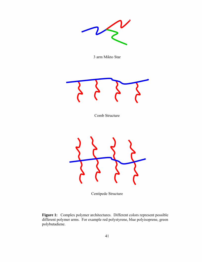
41
Figure 1: Complex polymer architectures. Different colors represent possible different polymer arms. For example red polystyrene, blue polyisoprene, green polybutadiene.
3 arm Mikto Star
Comb Structure
Centipede Structure
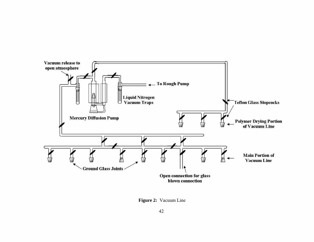
Figure 2: Vacuum Line
42

43
Figure 3: Glass constriction (left) and breakseal (right).

44
Figure 4: Solvent container with benzene and living polystyrene anion present as an indicator.
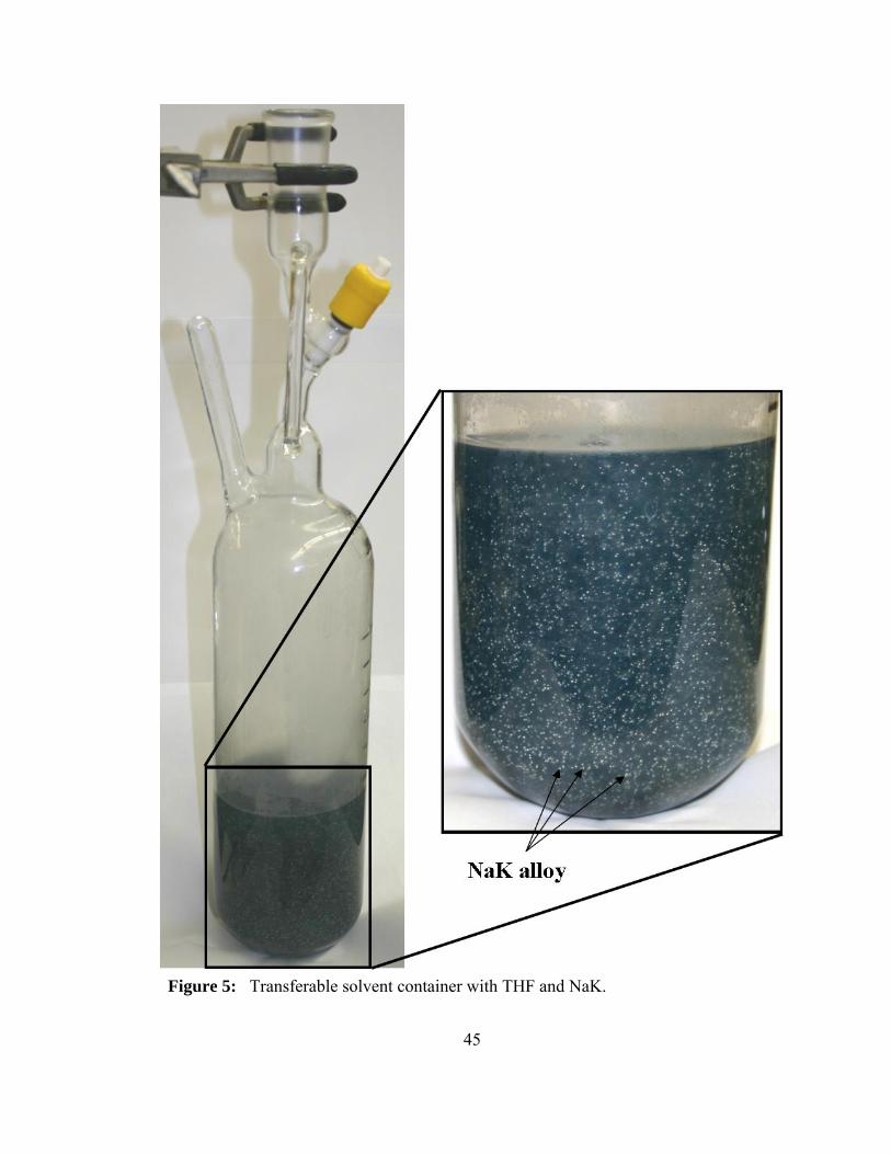
45
Figure 5: Transferable solvent container with THF and NaK.

46
Figure 6: Apparatus for distilling monomers.

47
Figure 7: Apparatus for distilling styrene and high boiling reagents.
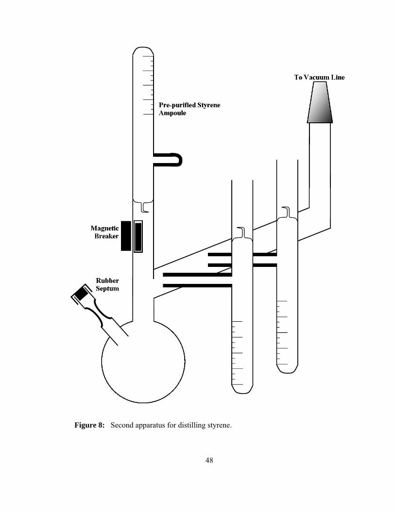
48
Figure 8: Second apparatus for distilling styrene.

49
Figure 9: Apparatus for synthesis of sec-butyl lithium.

50
Figure 10: Apparatus for synthesis of DMAPLi.

51
Figure 11: Photograph of all glass reactor.

52
Figure 12: Fracationation GPC timeline

53
Part 2
Synthesis and Characterization of Ω-Functionalized Multiarm
Star Branched Polyisoprenes and Poly(ethylene-co- Propylene)

54
Introduction
Research in oil additives for lubricating technologies has increased exponentially
over the last two decades. The need for viscosity index improvers (VII) to generate a
more stable viscosity curve over a wider range of temperatures is the main goal of the
current research. In addition to viscosity enhancement for synthetic oils, the additives
may also provide additional improvements including antioxidant properties, dispersant
properties, and encourage film formation. There are four main types of VII’s used today,
ethylene-propylene diene monomers (EPDMs), styrene-isoprene copolymers (SIC),
styrene-butadiene rubber copolymers (SBR), and poly alkyl methacrylates (PAM).
The use of EPDMs is the focus of this study specifically polyisoprene (PI) and
poly(ethylene-alt-propylene) (PEP). PEP polymers have been studied extensively
because they exhibit no crystallinity and possess high degradation temperatures (~420oC).
Star polymers have been used as VII’s for some time due to the fact that star
polymers degrade differently from their linear counter-parts. Linear high molecular
weight polymers can serve as VII’s; however, under high temperature and high shear
conditions chain breakage can cause severe degradation in the molecular weight of such
additives. Conversely, polymers with star architectures can lessen the effect of chain
breakage on an oil additive. A star molecule can under go chain breakage and absorb a
large decrease in molecular weight and still maintain a higher viscosity when compared
to a linear polymer.[1, 2]
Evidence has been published showing that incorporation of amine functionalities
into the polymer VII, either through grafting or copolymerization, can provide dispersing

55
qualities in an aliphatic oil system. The polymers that contain these functionalities
behave as detergents that help both remove and prevent the build up of sludge formation
in the engine. The incorporation of a polar compound can also significantly help the
formation of polymers with this type of behavior. [3-5]
Living anionic polymerization has been studied for many years and has been
researched extensively by Fetters and co-workers and as well as many other chemists[6-8].
Anionic polymerization affords the opportunity for well-defined complex architectures to
be created using a variety of electrophilic linking agents. A variety of functional groups
and protected anionic initiators can be utilized to create Ώ-functionalized polymers
through anionic polymerization[9, 10]. Ώ-functionalized star polymers are polymers that
have an end-functional group on the corona of the star. In this chapter we will examine
the synthesis of a series of PI and PEP polymers using anionic polymerization coupled
with chlorosilane and divinylbenzene linking chemistry.
Various star polymers have been synthesized in the past by Hadjichristidis and
coworkers.[11, 12] The star polymers synthesized by Hadjichristidis involved star
polymers with PI arms and varying chlorosilane linking agents. He utilized chlorosilane
linking agents that led to 8 arm, 12 arm, and eventually 18 arm stars. Roovers and
coworkers also synthesized star polyisoprene using chlorosilane linking agents to prepare
4 and 6 arm star material.[13] Chlorosilanes have proven to be a convenient method for
controlling the architectures of star polymers when used in conjunction with traditional
glass blowing techniques. However, one of the draw backs to utilizing the chlorosilanes
to synthesize many-armed star materials is the synthesis and subsequent characterization

56
of the chlorosilane material. Stars having fewer arms are easily accessible due to the fact
that tri, tetra, and hexafunctional chlorosilane linking agents are commercially available.
Another convenient method for synthesizing polymer stars is the use of
divinylbenzene as the linking agent. [10, 14-17] The control of the number of arms is
related to the ratio of living anion chain ends to moles of DVB present to perform the
crosslinking.[18] Precise control is difficult because there is no established relationship
between the number of arms and the ratio of DVB to living chain end. Also controlling
the number of arms is more complicated than just controlling the ratio of DVB/anion
because the number of arms is also related to the molecular weight of the arm material
and the concentration of anion in solution. This method of star formation leads to
byproducts consisting of unreacted arm material and coupled arm material that must be
fractionated and removed from the final star material.
To synthesize the star polymers for this study a variety of techniques were
utilized; chlorosilane chemistry and DVB chemistries were employed.
Experimental
Materials
Isoprene (Aldrich), benzene (Aldrich), and hexane (Aldrich) were purified
according to techniques described by Morton and coworkers[6]. Divinylbenzene (DVB)
(a mixture of 85 wt% para and 10 wt% meta divinylbenzene isomers, Aldrich) was
distilled over CaH2 and subsequently dibutylmagnasium then diluted with hexane.
Methyltrichlorosilane (Aldrich) and 1, 6-bis(trichlorosilyl)hexane (Aldrich)
(hexachlorosilane) were distilled over CaH2 using a specially made short path distillation

57
glass apparati for high temperature fractional distillation. The glass apparati were
silanated with trimethylchlorosilane (Aldrich) before use. The chlorosilanes were then
diluted with purified hexanes[8]. Dimethylaminopropylchloride (Aldrich) was purified
from CaH2 and ampoulized for synthesis of initiator. Xylenes (ACS reagent grade 98.5%
as xylenes and ethylbenzene, Aldrich), palladium on CaCO3 5% Pd, and palladium on a
matrix of activated carbon 5% Pd (Aldrich), were used without further purification. Tri-
n-propyl amine (TPA) (Aldrich) was used as received from Aldrich. p-Toluenesulfonyl
hydrazide (TSH) was also purchased from Aldrich Chemicals and was recrystallized
from methanol and dried in vacuum for 24 hours at 40oC prior to use.
Instrumentation
Gel permeation chromatography (GPC) was used to determine molecular weights
and molecular weight distributions (Mw/Mn) of polymer samples with respect to
polystyrene standards (Polymer Standard Services (PSS)). The system included two
styragel columns, which are PSS 5μ styrene-DVB cross-linked columns (1 x linear and 1
x 100 Ä 60 cm columns). A Waters Model 510 pump, a LDC Milton Roy UV detector,
and a Waters Model 410 differential refractometer were used as the hardware. The
mobile phase for the system was tetrahydrofuran (THF) at a flow rate of 1 mL/min. 1H
Nuclear Magnetic Resonance (NMR) spectra of the polymers were obtained on a Bruker
AC-300 spectrometer using 5 mm o.d. tubes. Sample concentrations were about 25%
(w/v) in CDCl3 containing 1% TMS as an internal reference. Thermogravimetric
Analysis (TGA) was used to probe the degradation temperatures for the polyisoprene and
poly(ethylene-co-propylene). The TGA was a TA Instruments Hi-Res Modulated TGA

58
2950. Differential Scanning Calorimeter (DSC) was utilized to record glass transition
temperatures for the polymers. The DSC was a TA Instruments Q1000. A Bruker 300
MHz NMR was used to characterize the saturation of the polyisoprene polymers.
Synthesis of 3-dimethylaminopropyllithium
The synthesis of dimethylaminopropyllithium (DMAPLi) was performed under
vacuum by the reaction of dimethylaminopropylchloride with lithium metal. The
DMAPLi was ampoulized and diluted with benzene. A detailed account of the synthesis
was written by Pispas and co-workers[19]. A sample of the product was extracted and
terminated with methanol then characterized using mass spectrometry. Two ampoules
were sacrificed to determine the concentration of the initiator. The first ampoule was
hydrolyzed then titrated with a HCl solution to determine the concentration of the
initiator. The amount of HCl used was twice the concentration of initiator due to the
amine group present in the formation of the HCl salt. Therefore the concentration of the
initiator was equivalent to the amount of HCl used divided by two. The second ampoule
was used to perform a test polymerization with a known amount of isoprene to determine
the amount of active initiator. The calculation for moles of initiator was made using the
following equation:
Moles initiator = grams of monomer/Mn (1)
Mn is the number average molecular weight recorded from GPC. These two methods of
determining the concentration of DMAPLi initiator coincided with one another once the
data from the GPC had been corrected to account for the hydrodynamic volume of
polyisoprene.
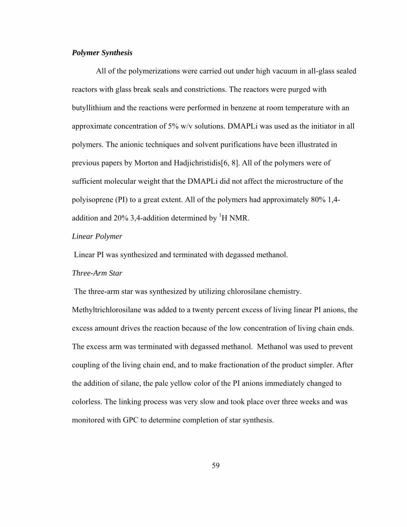
59
Polymer Synthesis
All of the polymerizations were carried out under high vacuum in all-glass sealed
reactors with glass break seals and constrictions. The reactors were purged with
butyllithium and the reactions were performed in benzene at room temperature with an
approximate concentration of 5% w/v solutions. DMAPLi was used as the initiator in all
polymers. The anionic techniques and solvent purifications have been illustrated in
previous papers by Morton and Hadjichristidis[6, 8]. All of the polymers were of
sufficient molecular weight that the DMAPLi did not affect the microstructure of the
polyisoprene (PI) to a great extent. All of the polymers had approximately 80% 1,4-
addition and 20% 3,4-addition determined by 1H NMR.
Linear Polymer
Linear PI was synthesized and terminated with degassed methanol.
Three-Arm Star
The three-arm star was synthesized by utilizing chlorosilane chemistry.
Methyltrichlorosilane was added to a twenty percent excess of living linear PI anions, the
excess amount drives the reaction because of the low concentration of living chain ends.
The excess arm was terminated with degassed methanol. Methanol was used to prevent
coupling of the living chain end, and to make fractionation of the product simpler. After
the addition of silane, the pale yellow color of the PI anions immediately changed to
colorless. The linking process was very slow and took place over three weeks and was
monitored with GPC to determine completion of star synthesis.

60
Six-Arm Star
The six-arm star was synthesized in the same manner as the three-arm star. 1, 6-
bis(trichlorosilyl)hexane was added to generate the star in this case. The reaction scheme
is described in Figure 1.
Multiarm Star
The multiarm star was synthesized using DVB as a linking agent. The DVB was added
to the living linear PI anions in a ratio of DVB/PI-Li ≈ 37/1. An immediate color change
was observed; the pale yellow color of the living PI changed to an orange color and
intensified over the next 20 minutes. The polymer was consequently terminated with
methanol after 4 days of linking time[20].
All of the polymers were precipitated in a large excess of methanol and stabilized
with butylated hydroxytoluene (BHT). The star polymers were fractionated using
toluene/methanol as the solvent/non-solvent mixture, being careful to add more BHT
with each ensuing fractionation to prevent oxidation of the polymer. The fractionation
was monitored with GPC. The final polymers were divided and half of each polymer was
subsequently hydrogenated.
Hydrogenation
Diimide Method
A variety of hydrogenation methods were attempted on the polyisoprene linear
and star polymers. An ambient pressure procedure using a Toluene Sulfonyl
Hydrizide/Tripropylamine (TSH/TPA) was used to generate the diimide species which is
the hydrogenating species. This reaction was chosen because the diimide method does

61
not require the use of a Parr reactor. The reaction was carried out on the linear
polyisoprene material sample PI Linear in a 500 mL round bottom flask which was fitted
with a magnetic stirrer and a reflux condenser, a thermometer, and a nitrogen inlet
stopper. A purge of nitrogen gas was introduced at the inlet and allowed to exit through
the top of the condenser via a bubbler filled with mineral oil. 5 grams of linear
polyisoprene was introduced into the flask with 300 mL of xylene. The polymer and
xylene were stirred overnight to ensure complete dissolution of the PI in the xylene.
22.0g of TPA and 27.4g of TSH were added to the polymer solution. The amount of
TSH/TPA provided a molar ratio of two TSH per site of unsaturation in the PI. An
antioxidant was added to prevent oxidation of the polymer during the hydrogenation
process: 2 grams of Irganox 1010 was introduced into the reactor. The TSH is only
slightly soluble at room temperature but upon heating the mixture becomes clear and
colorless. The reaction vessel was then heated to reflux and allowed to proceed once the
xylene had been refluxing for 4 hours. During that time the solution developed a dark
burgundy color. This color evolved slowly over the time of the reaction from a clear
solution, to a light yellow, proceeding to an orange solution that finally deepened into the
dark red color. After the reaction proceeded for 4 hours it was allowed to cool to room
temperature and then was washed with two 250 mL portions of deionized water to
remove the aqueous soluble byproducts. The remaining organic solution was filtered
through Celite to remove the solid material in the reaction. The resulting polymer was
precipitated in an excess of methanol with BHT added to provide protection against
oxidation. The resulting polymer was dried under vacuum overnight at 40oC to remove

62
any excess solvent. The polymer was then evaluated by proton NMR and GPC to
evaluate the extent of hydrogenation and examine the molecular weight of the polymer.
Palladium/Carbon Method
Two different methods of high pressure hydrogenation were attempted on the PI
samples. The first high pressure hydrogenation attempted involved 5% Pd by weight on
activated carbon. Five grams of polymer were dissolved in 250 mL of xylene and
introduced into a high pressure Parr reactor fitted with a glass insert. An equal amount of
Pd on carbon to polymer was used to perform the hydrogenation (5 grams). A small
amount of BHT was added to the solution to protect against oxidation. The amount of
BHT was less than 1% by weight of the entire solution. The Parr reactor was sealed and
promptly purged with hydrogen gas three times to a pressure of 400 PSI to ensure a clean
hydrogen atmosphere in the reactor. The reactor was then charged to a pressure of 700
PSI and heated to 80oC for 24 hours. At the conclusion of 24 hours, a sample of the
polymer was taken and filtered through a 5 μm disposable syringe filter to remove the Pd
on carbon. At this point proton NMR was performed to determine the extent of
hydrogenation, if hydrogenation was not greater than 95% complete the reaction was
resealed and purged again and run for a subsequent 24 hours. During subsequent
attempts at hydrogenation the solution was heated to 160oC to try to facilitate the reaction
progress. This process was repeated until the hydrogenation was completed. The
polymer was isolated by filtering the solution through a Celite pad by vacuum filtration.
The resulting polymer was precipitated in methanol and dried under vacuum for 24 hours.

63
Palladium/Calcium Carbonate Method
The third method of hydrogenation was similar to the method with Pd on carbon,
but in this procedure Pd on CaCO3 was utilized. Again equal amounts of Pd on CaCO3, 5
grams of the catalyst and 5 grams of PI were introduced into the Parr reactor. The reactor
was purged with hydrogen and then the reaction was run for 24 hours at which time a
sample was taken and proton NMR was performed. If the hydrogenation was not
completed the resulting reaction was re-purged and run for an additional 24 hours. As
described in the previous reaction, the reaction was heated to higher temperatures upon
the second and third reaction cycles of hydrogenation. The final solution was also
filtered through a Celite pad under vacuum filtration to remove the catalyst. The polymer
was then precipitated in methanol and dried under vacuum.
Results
Nuclear Magnetic Resonance Spectroscopy
An NMR study of the synthesis of the PEP polymer was used to determine the percent
hydrogenation of the PI. Most of the polymers were hydrogenated to greater than 95%
except for the polymer linked using DVB. DVB-PI polymer is harder to hydrogenate
because of steric hindrance located around the DVB micro-gel core of the polymer. A
micro-gel core is created during the cross-linking reaction of DVB, this gel core if larger
would be difficult to get into solution. (A highly cross-linked material that has
significantly high amount of cross linking will not be soluble in any solvent, the polymer
may swell but is never completely soluble, hence the term gel is applied to these types of
materials.) Since the core is surrounded by the arms of the star, the multiarm star is

64
easily soluble. The micro-gel core that is created limited the extent of hydrogenation to
90% saturation. An example of the NMR before and after hydrogenation can be seen in
Figure 3. Also in the NMR, the microstructure of the PI was examined by integration of
the olefinic peaks around 5 ppm. The integration of the peaks seen in Figure 3 at 5.1 and
a small peak at 5.4 ppm represent the 1,4 ppm cis and trans microstructure of the PI,
respectively. The doublet at 4.8 ppm represents the 3,4 addition of the monomer.[21]
1]4,3[2]4,1[]4,1[]4,1[]4,1[
]4,3[2)1.5()4.5(
)8.4(
=+−+−−+−
=+
additioncistranscistrans
additionppmIppmI
ppmI (2)
Using the equation 2 the amount of each type addition can be calculated. In this case I is
the intensity or area of the NMR signal which corresponds to the # ppm of that
signal.[21] The extent of hydrogenation was calculated by comparing the areas of the
double bond peaks to the aliphatic proton peaks from 1 ppm to 2.3 ppm, this ratio gave
the extent of hydrogenation. The typical microstructure of anionically polymerized PI in
the absence of a polar solvent is: ~10 wt% 3,4 addition, ~70 wt% cis 1,4 addition, and ~
20 wt% trans 1,4 addition of the monomer unit.[6] In all of the samples that were
synthesized the microstructure was approximately 80% 1,4 addition and 20% 3,4 addition.
This result is typical of the DMAPLi initiator.[19, 22] The DMAPLi serves as its own
polar additive which provides a benefit and restriction. The benefit of the DMAPLi
serving as its own polar additive is that a fast initiation occurs because the Li anion
aggregation is disrupted by the amine. The disruption in aggregation makes the
monosubstituted carbanion react faster with the first PI monomer unit and subsequent
monomer units. The restriction of this type of initiator is that the microstructure of the

65
polymer can only be controlled to the extent of the concentration of the initiator in
solution. Pispas and coworkers showed that varying the MW of PI which causes
variation in concentration of the DMAPLi initiator corresponds to changes in
microstructure distributions.
Differential Scanning Calorimetry
DSC was performed on all of the samples to determine the glass transition temperature
(Tg) and to check for any crystalline regimes in the polymer. All of the polymers
exhibited glass transition temperatures consistent with the literature value of -61.2°C for
100% 1,4 cis PI and -59.6°C for 80% 1,4 cis and 20 % 3,4 addition PI.[23] The measured
Tg for the PI and PEP samples were clustered around –59°C. No crystallinity was
observed for any of the PI or PEP samples. Crystallinity would be expected in linear
polyethylene, but the presence of the methyl group on the propylene unit and also the
added amount of 3,4 addition in the polymer back bone prevents any crystallinity from
being observed
Thermal Gravimetric Analysis
TGA was run on all of the samples. The PI samples and PEP samples were found to be
similar. The PI samples were all found to have an onset degradation point of 352°C,
while the PEP samples had an onset degradation temperature of 424°C. Hydrogenation of
polyisoprene greatly increased the thermal stability of the polymer, so that the new
degradation temperature was ~75°C higher.
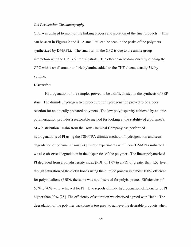
66
Gel Permeation Chromatography
GPC was utilized to monitor the linking process and isolation of the final products. This
can be seen in Figures 2 and 4. A small tail can be seen in the peaks of the polymers
synthesized by DMAPLi. The small tail in the GPC is due to the amine group
interaction with the GPC column substrate. The effect can be dampened by running the
GPC with a small amount of triethylamine added to the THF eluent, usually 5% by
volume.
Discussion
Hydrogenation of the samples proved to be a difficult step in the synthesis of PEP
stars. The diimide, hydrogen free procedure for hydrogenation proved to be a poor
reaction for anionically prepared polymers. The low polydispersity achieved by anionic
polymerization provides a reasonable method for looking at the stability of a polymer’s
MW distribution. Hahn from the Dow Chemical Company has performed
hydrogenations of PI using the TSH/TPA diimide method of hydrogenation and seen
degradation of polymer chains.[24] In our experiments with linear DMAPLi initiated PI
we also observed degradation in the dispersties of the polymer. The linear polymerized
PI degraded from a polydispersity index (PDI) of 1.07 to a PDI of greater than 1.5. Even
though saturation of the olefin bonds using the diimide process is almost 100% efficient
for polybutadiene (PBD), the same was not observed for polyisoprene. Efficiencies of
60% to 70% were achieved for PI. Luo reports diimide hydrogenation efficiencies of PI
higher than 90%.[25] The efficiency of saturation we observed agreed with Hahn. The
degradation of the polymer backbone is too great to achieve the desirable products when
67
using anionic polymerization. Even though Hahn has explored different ratios of diimide
to olefinic bonds, degradation was still observed. Due to the ill effects of this type of
hydrogenation alternative, high pressure methods were used to saturate the PI polymers.
The effects of the diimide hydrogenation were not explored on the polymers containing
the silane linkages due to the fact that a limited amount of star material had been
synthesized and isolated.
In my previous work with PBD, successful hydrogenation of the polymer was
achieved using 5% Pd on activated carbon. Hydrogenation of PBD with Pd on carbon
has also been reported by others[26, 27] Equal amounts of catalyst and polymer were
used when hydrogenating PBD; however, PI is slightly different in structure when
compared to PBD. In PBD the double bond is di-substituted, and in PI the double bond is
tri-substituted. The steric hindrance of the methyl group on the PI monomer unit makes
hydrogenation a great deal more difficult. The hydrogenation of PI is not successful with
Pd/C catalyst. Little or no hydrogenation was observed for linear and star material. The
polymers were hydrogenated less than 10% even after high temperatures and reaction
times lasting 72 hours. The large particle size of the heterogeneous catalyst is possibly
the reason the hydrogenation of the material is not successful. The Pd/C particles are
visually larger than that of Pd on CaCO3; therefore, this method of hydrogenation was
dismissed for the hydrogenation of PI polymers.
Hydrogenation with Pd on CaCO3 was successful as demonstrated in Figure 3.
The amount of saturation is evident due to the departure of the NMR signals between 4
and 6 ppm. The polymers were completely saturated after 48 hours of the reaction.

68
During the hydrogenation of the three and six arm stars, long reaction times, compiled
with high pressure and temperature, caused reformation of the arm. This can be seen in
the GPC traces in Figure 4. The reformation of the arm is clearly visible by the bimodal
peaks. The lower MW peak corresponds approximately to the initial arm material in
molecular weight and polydispersity. The variation in MW from the original arm
material is due hydrogenation of the PI which causes a shift in the GPC to a slightly
higher MW peak. This shift was also seen in the DVB star that did not degrade during
the hydrogenation process. The small shift can be seen in Figure 2.
Attempts to fractionate the bimodal material for the three and six arm stars were
unsuccessful. The toluene/methanol solvent/non-solvent pair was inadequate to perform
the fractionation. The fractionation solutions never separated fully and the polymer
coated the inside of the separatory funnel instead of forming a phase-separated material.
The reformation of the arm demonstrates that the change in MW is due to the silicon
carbon bond being cleaved. Cleavage of silicon-carbon bond is further verified by the
fact that the DVB star polymer and the linear PI’s molecular weight and distribution did
not change when exposed to the same reaction conditions.
Conclusions
Through coupling chemistry using chlorosilanes and cross-linking chemistry
using DVB, different types of star PI have been synthesized using anionic polymerization.
The synthesis and characterization of PI and PEP polymers have been performed using
TGA and DSC to probe the thermal stabilities and glass transition properties. We expect

69
significant advantages in the use of the PEP polymers as VII’s due to their high onset
degradation temperature.
Initially the hydrogenation of the samples proved to be challenging due to
degradation during the reaction. We believe that the diimide process of hydrogenation is
not sufficient to use on anionically prepared polymers due to significant increases in the
polydispersities of our polymer samples. The successful hydrogenation of PI was due to
smaller particle size of the Pd on CaCO3 catalyst when compared to Pd on activated
carbon. Pd on activated carbon was adequate to hydrogenate PBD in previous work due
to the fact the olefinic bond is more sterically accessible than PI. We believe that Pd on
CaCO3 would also be a good alternative method for the hydrogenation of PBD since
particle size is not an issue with PBD. The hydrogenation of the PI samples with Pd on
CaCO3 has proven to be the best method for the hydrogenation of the narrow disperse PI
polymers in our research. The methyl group attached to the isoprene repeat unit limits
the access of the larger Pd on carbon catalyst. Hydrogenation of PI using a homogenous
catalyst should provide a better method of hydrogenation than heterogeneous catalyst due
to the hindered olefinic bond.
The goal was to obtain well-defined polymers; which is the main reason that
anionic synthesis was chosen for this particular project. A well defined PEP star polymer
and linear PEP material functionalized with amine end-groups should provide some
insight into the world of VII’s. The use of Pd on CaCO3 with much shorter reaction
times coupled with lower temperatures should assist in the isolation of PEP star polymers

70
and prevent the degradation during the hydrogenation process for stars linked with
chlorosilanes.
The polymers synthesized during this project show promise as VII’s due to their
well defined nature, and higher degradation temperatures then VII’s containing olefinic
bonds. Correlation of viscosity properties with molecular weight and structure should
provide insight into producing a better quality VII. Further studies will be performed
using the polymers synthesized during this project to probe viscosity properties in
synthetic oils, such as synthetic oil PAO4 from Castrol.

71
References
72
1. Liou, I.-C.; Tsiang, R. C.-C.; Wu, J.; Liou, J.-S.; Sheu, H.-C. Journal of Applied Polymer Science 2002, 83, (9), 1911-1918.
2. Chen Hou; Qu, R.-j.; Ying, L.; Wang, C.-g. Journal of Applied Polymer Science 2005, 97, (2), 527-531.
3. Mishra, M. K.; Rubin, I. D. Functionalized graft co-polymer as a viscosity and index improver, dispersant, and anti-oxidant additive and lubricating oil composition containing same 5,409,623, 1995.
4. Mishra, M. K.; Rubin, I. D. Antioxidant-dispersant VI improver additive and lubricating oil composition containing same 5,264,140, 1992.
5. Biswell, C. B.; Catlin, W. E.; Froning, J. F.; Robbins, G. B. Ind. Eng. Chem. 1955, 47, (8), 1598-1601.
6. Morton, M.; Fetters, L. Rubber Chem. Technol 1975, 48, 359.
7. Hadjichristidis, N.; Xenidou, M.; Iatrou, H.; Pitsikalis, M.; Poulos, Y.; Avgeropoulos, A.; Sioula, S.; Paraskeva, S.; Velis, G.; Lohse, D. J.; Schulz, D. N.; Fetters, L. J.; Wright, P. J.; Mendelson, R. A.; Garcia-Franco, C. A.; Sun, T.; Ruff, C. J. Macromolecules 2000, 33, (7), 2424-2436.
8. Hadjichristidis, N.; Iatrou, H.; Pispas, S.; Pitsikalis, M. Journal of Polymer Science Part A: Polymer Chemistry 2000, 38, (18), 3211-3234.
9. Shultz, D. N.; Sanda, J. C.; Willoughby, B. G. ACS Symp. Ser. 1981, 166, 427.
10. Elkins, C. L.; Viswanathan, K.; Long, T. E. Macromolecules 2006, 39, (9), 3132-3139.
11. Hadjichristidis, N.; Fetters, L. J. Macromolecules 1980, 13, (1), 191-193.

73
12. Hadjichristidis, N.; Guyot, A.; Fetters, L. J. Macromolecules 1978, 11, (4), 668-672.
13. Roovers, J. E. L.; Bywater, S. Macromolecules 1974, 7, (4), 443-449.
14. Williamson, D. T.; Elman, J. F.; Madison, P. H.; Pasquale, A. J.; Long, T. E. Macromolecules 2001, 34, (7), 2108-2114.
15. Frater, D. J.; Mays, J. W.; Jackson, C. Journal of Polymer Science Part B: Polymer Physics 1997, 35, (1), 141-151.
16. Ishizu, K.; Sunahara, K. Polymer 1995, 36, (21), 4155-4157.
17. Bi, L.-K.; Fetters, L. J. Macromolecules 1978, 8, (1), 90-92.
18. Bi, L.-K.; Fetters, L. J. Macromolecules 1976, 9, (5), 732-742.
19. Pispasa, S.; Pitsikalisa, M.; Hadjichristidis, N.; Dardani, P.; Morandi, F. Polymer 1995, 36, 3005.
20. Hsieh, H. L.; Quirk, R. P., Anionic Polymerization. Marcel Dekker, Inc.: New York, New York, 1996.
21. Yasuyuki Tanaka, Y. T. M. K. H. T. Journal of Polymer Science Part A-2: Polymer Physics 1971, 9, (1), 43-57.
22. Neil S. Davidson, L. J. F., Walter G. Funk, William W. Graessley, Nikos Hadjichristidis. Macromolecules 1988, 21, (1), 112-121.
23. Olson, B. G.; Srithawatpong, R.; Peng, Z. L.; McGervey, J. D.; Ishida, H.; Maier, T. M.; Halasa, A. F. Journal of Physics: Condensed Matter 1998, 10, (46), 10451.
24. Hahn, S. F. Journal of Polymer Science Part A: Polymer Chemistry 1992, 30, 397-408.

74
25. Yanming, L. Journal of Applied Polymer Science 1995, 56, (6), 721-737.
26. Holleben, M. L. z. A.; Silva, S. M.; Mauler, R. S. Polymer Bulletin 1994, 33, (2), 203-208.
27. Liao, C. X.; Weber, W. P. Polymer Bulletin 1993, 31, (3), 305-309.

75
Appendix

76
Li N LiN Cl
N Li N HN Li
Si
Cl
Cl
ClN N
Si
N
N
N
NSi
SiCl
Cl Cl
Cl Cl
ClN
N
N
N
N
N
N N
Si
N
N
N
Si
N
N
N
1. Hexane
2. Benzene
Benzene1. MeOH
Figure 1: Reaction scheme for linear PI and PI star synthesis.
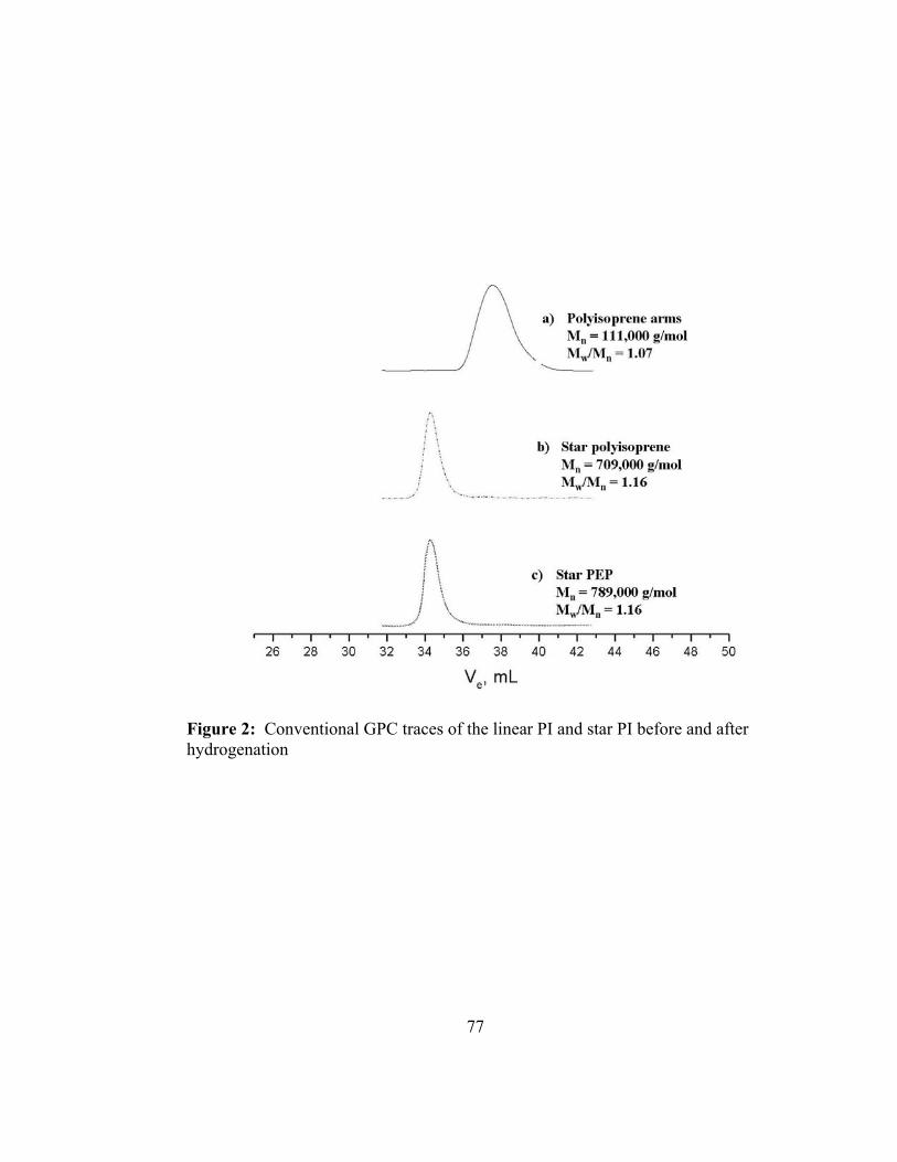
77
Figure 2: Conventional GPC traces of the linear PI and star PI before and after hydrogenation

78
a) Linear polyisopreneafter hydrogenation with Pd/CaCO3
b) Linear polyisoprenebefore hydrogenation
ppm
a) Linear polyisopreneafter hydrogenation with Pd/CaCO3
b) Linear polyisoprenebefore hydrogenation
ppm
Figure 3: NMR of linear PI before and after hydrogenation. The hydrogenation of this material was carried out using Pd on CaCO3. Note that there are no residual peaks in the 4 to 6 ppm region after hydrogenation.
1,4 trans addition
1,4 cis addition
3,4 addition

79
Figure 4: GPC traces of 6 arm PI before(top) and after(bottom) hydrogenation.

80
Conventional GPC Sample PI Arm Material Mw/Mn Star Mn Mw/Mn
PI Linear 111,000 1.07 ------------ ------------PI 3 arm 101,000 1.06 216,000 1.09 PI 6 arm 106,000 1.05 353,000 1.09
PI multi-arm 111,000 1.07 709,000 1.16
PEP Linear ------------ ------------ 114,000 1.08 PEP 3 arm ------------ ------------ Bimodal ------------PEP 6 arm ------------ ------------ Bimodal ------------
PEP multi-arm ------------ ------------ 789,000 1.16
GPC with Online Light Scattering Sample PI Arm Material Mw/Mn Star Mn Mw/Mn
PI Linear 70,000 1.07 ------------ ------------PI 3 arm 58,000 1.06 186,000 1.03 PI 6 arm 61,000 1.06 335,000 1.03
PI multi-arm 69,000 1.07 1,230,000 1.05
PEP Linear ------------ ------------ ------------ ------------PEP 3 arm ------------ ------------ Bimodal ------------PEP 6 arm ------------ ------------ Bimodal ------------
PEP multi-arm ------------ ------------ ------------ ------------
Table1: PI and PEP samples examined by convention GPC and online light scattering GPC.

81
Part 3
Characterization of Model Branched
Polymers by Multi-Detector SEC in Good and Theta Solvents
82
Introduction Size exclusion chromatography (SEC) has proven to be a valuable tool for
characterization of polymers since its beginnings in the 1960’s[1]. Conventional SEC
employs calibration with linear standards, most commonly narrow molecular weight
distribution (MWD) polystyrene (PS) standards since materials covering an extremely
broad range of molecular weights may be purchased from commercial vendors.
Conventional calibration curves thus generated are strictly valid only for linear PS and
will generate erroneous results if applied to other linear polymers, or to branched
polymers, including PS. An important breakthrough in SEC calibration was the discovery
by Grubisic et al. that SEC separates on the basis of hydrodynamic volume[2]. These
workers demonstrated that data plotted in the form of log ([η]M) versus VR, where [η] is
intrinsic viscosity, M is molecular weight, and VR is retention volume, fell on a single
curve for different polymer types and for different branched architectures and
copolymers. Thus, if data on intrinsic viscosities are available for polymers being
analyzed, the PS standard calibration can be converted to a universal calibration curve
that will give accurate molecular weights. SEC universal calibration is important and
widely used but somewhat controversial. Theory and simulations assume a
thermodynamic separation principle for SEC based on the fact that hydrodynamic factors
have little effect on molecular separation. Thus most theories use the radius of gyration
Rg as the relevant size parameter. However, recent work by Sun et al. and Teraoka have
shown that the hydrodynamic radius (RH) correlates better with elution behavior of
branched molecules than does Rg[3, 4].

83
The use of on-line viscometers and on-line light scattering detection has become
popular in recent years, spurred by advances in instrumentation and computer
interfacing[5-7]. The use of the viscosity detector facilitates universal calibration;
whereas light scattering detection can be used to directly measure the molecular weight
of eluting fractions (calibration of the SEC is not required). Furthermore, whereas
classical characterization of dilute solution properties required fractionation in order to
obtain narrow molecular weight fractions with which to explore solution properties, the
combination of light scattering and viscometry with SEC allows for the various fractions
of a polydisperse sample to be characterized in a single injection[8, 9].
Recent developments have led to two-angle laser light scattering (TALLS)
detectors (150 and 900) capable of performing both static and dynamic light scattering
measurements on-line[10-12]. This progression in online measurements have allowed for
improved characterization of polymers by investigating a number of different parameters.
The ρ-ratio (ρ = Rg/RH) provides information on the shape and conformation of linear and
branched polymers in solution, in both good and theta solvents[11]. In terms of branched
polymers, the g parameter[13] is defined as the ratio of the radius of gyration of the
branched molecule relative to that of the linear molecule of the corresponding molecular
weight.
g = <R2g>b/<R2
g>l (1)
The g parameter will always have values < 1 for a branched polymer, reflecting the
smaller dimensions of branched species. In a similar manner, the g’ contraction
parameter is defined as the ratio of the intrinsic viscosity of a branched molecule
compared to that of the linear molecule of the corresponding molecular weight[9, 14].

84
g’ = [η]b/[η]l (2)
These two branching parameters are related by a factor ε:
g’ = gε (3)
Zimm and Kilb predicted the value of ε to be ½ for star polymers[15], but there is still
much debate about the value of ε for different branched architectures and whether the
parameter is universal for all branched polymers [14]. A knowledge of the value of ε is of
practical importance since Rg is often difficult to measure for branched polymers due to
their smaller sizes and the corresponding lack of angular dependence of the scattering
intensity. The intrinsic viscosity, however, can be measured accurately down to very low
molecular weights, but knowledge of the dependence of g’ on structure is not developed
quantitatively as it is for g. Another important point is that the calculations used to derive
the g branching parameter are based on the Gaussian coil approximation, which is closely
approximated under theta solvent conditions[13]. However very few SEC experiments
are run under theta conditions, where polymer adsorption on the stationary phase is a
problem, but instead are nearly always carried out under good solvent conditions[16, 17].
In this study, Rg, RH, and intrinsic viscosity data were generated via multi-detector
SEC for regular comb and centipede polystyrenes in both a thermodynamically good
solvent (tetrahydrofuran, THF) and a theta solvent (trans-decalin). These data allow a
comparison of the various methods for generating SEC universal calibration curves. In
addition, these data are used in deriving the value of the ε parameter for these model
multi-branched polymers and in computing values of universal dilute solution
parameters.

85
Experimental
Synthesis
The centipede and comb polymers used in this study were synthesized using
anionic polymerization. The centipede polystyrene samples were previously prepared by
Iatrou et al[18], while the comb polystyrene was previously synthesized by Nakamura et
al[10]. A detailed account of the synthesis has been described in these papers and is
summarized in Figures 1 and 2 (All figures are located in the appendix at the end of this
part of the thesis). The broad molecular weight linear polystyrene sample used in this
study was a commercial sample obtained from Aldrich which had a reported broad Mn of
280,000 and a polydispersity of 2.4.
Characterization
SEC investigation of the samples under good solvent conditions was performed in
HPLC grade THF (obtained from Fisher Scientific) at a flow rate of 1 mL/min. The SEC
unit was a Polymer Laboratories (PL) GPC-120 equipped with two PL-Gel 10 micron
mixed B columns. Incorporated in the SEC was a Precision Detectors PD-2040 two
angle light scattering detector (15 0and 900) detector for performing static and dynamic
light scattering (DLS) measurements. The system was also equipped with a Viscotek
differential viscometer. The system was run at a reduced flow rate (0.5 mL/min) and
higher concentration (10 mg/mL) to obtain better signal to noise ratio for the DLS
measurements. All of the measurements for THF were performed at 400C. The light
scattering detectors were calibrated with a low polydispersity 50,000 molecular weight
polystyrene standard. The refractive index increment (dn/dc) value used was 0.184 cm3g-
86
1; measured on a Wyatt Optilab DSP detector at a wavelength of 690 nm and temperature
of 40 oC. The Rg data and molecular weight data were obtained using the Discovery 32
software from Precision Detectors. The DLS correlation data was obtained using
Precision Acquire 32 software in conjunction with the Discovery 32 software from
Precision Detectors. The data obtained from TALLS and multi angle laser light
scattering (MALLS) data has been compared in recent literature and errors associated
with TALLS data and the calculation of has Rg been reported as less than 2% over a
broad molecular weight range.[12]
The SEC characterization of the samples under theta conditions was performed on
the same instrument with a slightly different configuration. The theta conditions chosen
were trans-decalin (TCI America) at 21-220C, and the detectors were maintained at this
temperature. The columns were heated separately in an Alltech 330 Column Heater to
1100C to obtain good solvent conditions preventing adsorption of the PS samples onto the
columns. trans-Decalin has a high boiling point which allows for the higher temperatures
to be maintained during the separation process and prevent adsorption[19-21]. This
system was also run at a slower rate and higher polymer concentrations in order to obtain
the DLS data. Multiple samples were run to determine the flow rate necessary to obtain
reliable DLS data. Since DLS is dependent on the correlation function of a given
solution, a slower flow rate of the GPC instrument allows for better correlation functions
to be examined. Slower flow rates allow more data points to be measured, opposed to the
situation where the flow rate is fast and the amount of time the sample is in the detector
volume is much smaller. Therefore the slower flow rate was necessary in order to obtain
more data points than faster flow rates, to obtain a similar amount of data points taken

87
during the Rg measurement. The signal to noise ratio for DLS data is dependent on with
GPC flow rates. A study was conducted in which a stop flow study was performed with
varying correlation time function were measured and compared to data obtained from
flowing DLS measurements and the error was less than 5% between stop flow
measurements and flow mode measurements.[11] The detectors were also calibrated
with the same polystyrene standard. The dn/dc value used for the theta condition was not
needed for the TALLS system because we calibrated the system with the polystyrene
standard.
Results and Discussion Molecular characteristics of the polymers used in this study are presented in Table
1. Using the chosen synthetic strategies, well defined polymers with fixed spacing
between branch points and fixed branch lengths were achieved. The synthetic strategy
involves the synthesis of a branch polystyrene and end-capping the branch polymer with
a chlorosilane linking agent such that only one or two active sites are reacted as is the
case with the comb polymer and centipede polymer respectively. Once the branch
polymers have been capped with the linking agent another polystyrene polymer was
synthesized with a difunctional lithium initiator that has been described in an earlier part
of this dissertation. This is where the so called “condensation reaction” or step growth
polymerizations takes place. The polystyrene polymer with two living chain ends is
slowly allowed to react with the chlorosilane capped polymers. The difunctional
polystyrene becomes the back bone of the polymer and the initially synthesized
polystryenes capped with chlorosilanes become the branches. So in the case of a comb
polymer there is one branch point between each back bone spacing and there are two

88
branches at each point between the centipede back bone spacing. Also an advantage of
the method is the ability to create samples that contain many species having different
numbers of branch points, resulting from the final step-growth polymerization process
that connects the backbone segments and side chains. Thus, in SEC the polymers are
effectively fractionated according to their degrees of branching, with higher molecular
weight polymers having larger numbers of branch points eluting first, followed by lower
molecular weight polymers having fewer branch points. Thus, data on a variety of
different branched species may be obtained in a single SEC experiment.
Radii of gyration for these polymers in THF and in trans-decalin at the theta
temperature using multi-detector SEC and the instrumentation and methods described
above have been previously reported by us[12]. In this work it was demonstrated that
two-angle light scattering generates Rg and M values essentially identical to those
generated using a 16-angle instrument. Furthermore, the power law exponents for linear
PS in the two solvents exhibited their expected values, and branched specimens exhibited
reduced radii of gyration relative to their linear counterparts.
Figure 3 shows a double logarithmic plot of the hydrodynamic radius versus the
molecular weight for branched and linear PS samples in THF. The power law
relationship for the linear sample falls within range compiled by Fetters et al[22]. In this
study we observed
RH = 1.90 x 10⁻² M 0.544 (4)
compared with [22]
RH = 1.44 x 10⁻² M 0.561 (5)

89
This agreement confirms the validity of the method, although it is clear that there is
scatter in the data at the high and low molecular weight ends of the distributions,
reflecting their lower concentrations. In general, the scatter is greater for on-line DLS
data as compared to online static light scattering and intrinsic viscosity data. The data for
on-line DLS measurements is a time dependent measurement so slower flow rates
generate more data points. As stated earlier, real time measurements for static light
scattering and viscosity provide more data at faster flow rates as opposed to the DLS
data. This is why more scatter is shown in DLS measurements.
The data for the branched polymers may also be fit by power laws. Clearly, these
data fall below the line for the linear material, and this deviation is larger as the percent
mass in the polymer side chain is increased. Also centipede sample g40-25 curve
coincides with the comb sample CS25-35 curve, reflecting the fact that, although one has
a single branch at every branch point while the other has two branches at each branch
point, each sample contains similar weight fraction of side chain.
These trends correlate well with the viscometry data (Figure 4). Again, the power
law plot of the viscosity correlates well with data by Fetters and coworkers for linear
polystyrenes:
[η] = 1.21 x 10⁻² M 0.718 (6)
compared with [22]
[η] = 9.96 x 10⁻³ M 0.734 (7)

90
As with the DLS data, the viscosity data for the branched polymers may also be well fit
by power laws and the same branching trends are followed. For samples having a greater
proportion of their mass in the side chain, the departure from the linear PS line increases
reflecting their smaller sizes. The data for the centipede sample g40-25 curve again
coincides with that for the comb sample CS25-35 which has the similar portion of its
mass in the side chains. It is also obvious that the data obtained by on-line viscometry
show less scatter than data obtained via DLS; nevertheless, the trends in the data are the
same.
In Figure 5 the RH data under theta conditions are summarized. It must be noted
that we have assumed the theta temperature for the branched polymers to be the same as
that for linear PS, and this assumption may not be strictly true although differences would
be expected to be small. The linear sample gives a power law relationship of
RH = 4.09 x 10⁻² M 0.451 (8)
where the exponent is slightly smaller than the value of ½ expected in a theta solvent.
The branched samples follow the same trends as in the good solvent. Unfortunately we
were unable to obtain reproducible viscometry data, apparently due to adsorption of the
polymer on the capillary giving spurious data. A viscometer constructed of a different
capillary material may provide a solution to this problem.
Since values of both g’ and g were obtained for the samples in the good solvent,
THF, we can calculate the exponent ε for these comb and centipede samples. In Table 2
we summarize the values calculated for polymers having regularly spaced branch points
in this study and compare them with values reported previously for combs having

91
randomly spaced branch points [14, 23-25]. We report a range of ε values because ε
changes slightly as the molecular weight changes in our samples. Recall that the number
of branch points increases as the molecular weight of the polymer increases for these
polydisperse specimens. As molecular weight is increasing the chain is changing its
characteristics by becoming stiffer. It is not possible to plot ε with molecular weight due
to the fact that the molecular weight is increasing in distinct molecular weight steps
where the architecture is changing from step to step. This becomes more evident in the
parameter Φ described in the next equation. It is clear from Table 2 that a value of ε of
approximately 0.9 is a good fit for all of these multi-branched polymers. Interestingly,
values of about 0.9 have also been determined for randomly branched poly(methyl
methacrylate) in the good solvent THF[9]. Furthermore, our present results also find good
agreement with theory reported by Berry, who suggested that as the fraction of monomer
units in the backbone increases for a range of the number of branches per molecule that ε
tends towards unity[26].
The availability of both thermodynamic data and thermodynamic parameters for
the model branched polymers also allow us to compute various “universal ratios”. The Φ
parameter, also known as the Fox-Flory factor was originally derived to be independent
of polymer structure, but has shown to fluctuate with varying architecture.
M [η] = 63/2ΦR3g (9)
The Φ parameter is often called a universal constant, but in reality its value depends on
architecture, local solvent conditions and local structure[27]. In Figure 6, we plot the
experimentally determined Φ values as a function of molecular weight of the polymer

92
samples. We obtain a value for the linear material that corresponds with the literature
value of 1.8 x 10²³ mol -1 which is for polymers in a good solvent, approximating the case
of polystyrene in THF[8]. It is interesting that the curves of g40-25 and CS25-35 also
correspond with one another, as they have in the previous Figures1-4. It is evident from
the plots that the Φ is changing with the changing architectures of each sample and is not
constant. Φ increases with the percent mass in the arms.
The ρ parameter is the ratio of the radius of gyration to the hydrodynamic radius
and is expected to exhibit values of 1.2-1.5 for a linear random coils and 0.775 for a hard
sphere[28]. In Table 3 measured values of ρ for all the samples are compared in good
and theta solvents. The values for linear PS are in the expected range, and as the relative
amount of mass in the side chain of the branched polymers increases ρ exhibits lower
values, smaller than that for linear coils and approaching hard sphere behavior which has
been observed for highly branched species like many-armed stars[29].
The Flory-Scheraga-Mandelkern β parameter
β = (M[η]/100)1/3/[f] (10)
exhibits values that decrease slightly from the linear chain theta solvent value (2.27 x10⁶
mol-1/3) with improved solvent quality and branching. We find values of 2.0x10⁶ for
linear PS in THF and values of 1.8-1.9x10⁶ for the regular combs and centipedes in THF.
These values are close to the value of β = 2.05x10⁶ reported for many armed stars in a
theta solvent[30].
In Figures 7-11 we use the various data obtained to construct “universal
calibration curves”. Figure 7 is a plot of the universal calibration curve based on
hydrodynamic volume ([η] M) in THF for all the polymers used in this study. The plot

93
was generated from the measured values of MW and the corresponding viscosity for the
slice of data measured during the GPC injection. While there is some scatter in the data,
this plot appears to be effective for reducing data for branched and linear polymers to a
common calibration curve. This corresponds to the theory proposed by Teraoka, that
states RH correlates better to the interstitial volumes present in the GPC column more so
than Rg.[4] In Figures 8 and 9, we compare, respectively, the plots of Rg and RH versus VR
of the polymers in the good solvent THF. While neither plot is as good as the standard
hydrodynamic calibration plot, clearly RH does a much better job than Rg of reducing the
data for linear and branched polymers to a common curve. In Figures 10 and 11, we plot
Rg and RH versus VR under theta solvent conditions. The latter plot nicely reduces all the
data to a single universal calibration curve, while the former plot fails to do so. Other
recent work has shown that RH correlates better with elution behavior of branched chains
than does Rg[3, 4]. Figures 9 and 11 match well with the theory proposed by Teraoka,
but universal calibration by hydrodynamic volume is generally still a better choice for
calibrating SEC, even in the case of branched molecules. A very noticeable feature to all
of the figures is that the same samples g40-25 and CS25-35 coincide in every instance.
These two samples provide insight into the fact that the location of the branch point on
the polymer backbone is not as important as how much or big the branch is protruding
from the back bone.
Conclusions
SEC with online static and dynamic light scattering and intrinsic viscosity
detectors was used to probe the dilute solution properties of linear, regular comb, and

94
regular centipede polystyrenes in both good and theta solvents. Measurements under
theta conditions were made possible by choosing trans-decalin as a theta solvent. This
solvent is a theta solvent for linear PS at room temperature, and its high boiling point
allows the chromatography to be conducted at elevated temperatures where it becomes a
good solvent for PS, avoiding adsorption of the polymer on the stationary phase. In this
work, SEC with static and dynamic light scattering detection, plus viscometry, has thus
been shown to be a powerful technique for generating comprehensive dilute solution
properties data on polymers, even under theta conditions. The ε parameter relating g and
g’ was shown to have a value of about 0.9 for regular comb and regular centipede
polystyrenes, in agreement with theory and data on random combs and certain randomly
branched polymers. Φ and β parameters provide further insight to the validity of the data
we collected due to the fact that the linear samples that were measured correlated well
with those reported in the literature. All dilute solution properties measured were found
to be in agreement with theory and other experimental studies on branched polymer
systems. This is the first time that these types of measurements have been performed and
compared to the theory for theta conditions. It must be noted here that although our
intrinsic viscosity studies failed under theta conditions, this is attributed to adsorption in
the viscometer capillary rather than an inherent limitation of the technique. Generation of
precise DLS data, using the present instrumentation, requires the use of reduced flow
rates to enhance the signal to noise ratio in the correlation functions.
Traditional SEC universal calibration based on hydrodynamic volume is the best
method at this time. The use of the hydrodynamic radius also gives fairly good universal

95
calibrations particularly at the theta conditions, however radius of gyration is not a useful
parameter for generating SEC universal calibration curves.

96
References
97
1. Moore, J. C. Journal of Polymer Science Part A: General Papers 1964, 2, (2), 835-843.
2. Z. Grubisic, P. R. H. B. Journal of Polymer Science Part B: Polymer Letters 1967, 5, (9), 753-759.
3. Sun, T.; Chance, R. R.; Graessley, W. W.; Lohse, D. J. Macromolecules 2004, 37, (11), 4304-4312.
4. Teraoka, I. Macromolecules 2004, 37, (17), 6632-6639.
5. Max, A. H. Journal of Applied Polymer Science 1985, 30, (7), 3023-3036.
6. Yau, W. Chemtracts, Macromol. Chem 1993, 1, 1.
7. Wyatt, P. J. Analytica Chimica Acta 1993, 272, (1), 1-40.
8. Jackson, C.; Chen, Y.-J.; Mays, J. W. Journal of Applied Polymer Science 1996, 61, (5), 865-874.
9. Christian Jackson, Y.-J. C., Jimmy W. Mays. Journal of Applied Polymer Science 1996, 59, 179-188.
10. Nakamura, Y.; Wan, Y.; Mays, J. W.; Iatrou, H.; Hadjichristidis, N. Macromolecules 2000, 33, (22), 8323-8328.
11. Liu, Y.; Bo, S.; Zhu, Y.; Zhang, W. Polymer 2003, 44, (23), 7209-7220.
12. Terao, K.; Mays, J. W. European Polymer Journal 2004, 40, (8), 1623-1627.
13. Zimm, B. H.; Stockmayer, W. H. Journal of Chemical Physics 1949, 17, 1301-14.
14. Radke, W.; Mueller, A. H. E. Macromolecules 2005, 38, (9), 3949-3960.
15. Zimm, B. H.; Kilb, R. W. Journal of Polymer Science 1959, 37, 19-42.
16. Lee, H. C.; Chang, T.; Harville, S.; Mays, J. W. Macromolecules 1998, 31, (3), 690-694.
17. Terao, K.; Farmer, B. S.; Nakamura, Y.; Iatrou, H.; Hong, K.; Mays, J. W. Macromolecules 2005, 38, (4), 1447-1450.
18. Iatrou, H.; Mays, J. W.; Hadjichristidis, N. Macromolecules 1998, 31, (19), 6697-6701.

98
19. Dawkins, J. V.; Hemming, M. Makromolekulare Chemie 1975, 176, (6), 1777-93.
20. Dawkins, J. V.; Hemming, M. Makromolekulare Chemie 1975, 176, (6), 1795--813.
21. Dawkins, J. V.; Hemming, M. Makromolekulare Chemie 1975, 176, (6), 1815-28.
22. Fetters, L. J.; Hadjichristidis, N.; Lindner, J. S.; Mays, J. W. Journal of Physical and Chemical Reference Data 1994, 23, (4), 619-40.
23. Hadjichristidis, N.; Xenidou, M.; Iatrou, H.; Pitsikalis, M.; Poulos, Y.; Avgeropoulos, A.; Sioula, S.; Paraskeva, S.; Velis, G.; Lohse, D. J.; Schulz, D. N.; Fetters, L. J.; Wright, P. J.; Mendelson, R. A.; Garcia-Franco, C. A.; Sun, T.; Ruff, C. J. Macromolecules 2000, 33, (7), 2424-2436.
24. Roovers, J. Polymer 1979, 20, 843-849.
25. Roovers, J. Polymer 1975, 16, 827-832.
26. Berry, G. C. Journal of Polymer Science, Part B: Polymer Physics 1988, 26, (5), 1137-42.
27. Konishi, T.; Yoshizaki, T.; Yamakawa, H. Macromolecules 1991, 24, (20), 5614-22.
28. Kurata, M.; Fukatsu, M. Journal of Chemical Physics 1964, 41, (9), 2934-2944.
29. Mays, J. W.; Hadjichristidis, N. Journal of Applied Polymer Science: Applied Polymer Symposium 1992, 51, (Polym. Anal. Charact. IV), 55-72.
30. Roovers, J.; Hadjichristidis, N.; Fetters, L. J. Macromolecules 1983, 16, (2), 214-20.

99
Appendix

100
Li-PS-LiLiLi
Li-PBD-PS-PBD-Li2 Units
THF additive
Benzene
Li PSLi
Si
Cl
Cl Cl
Cl PSSi
Cl
Cl
Cl
PS-Li PS-Si-PSCl
Cl
+Benzene
1.3:1C-Li: SiCl4
Titrate
Li-PBD-PS-PBD-LiRatioLi:Cl1.2:1
PS-Si-PSCl
Cl
Figure 1: Polystyrene centipede synthesis. Notice that each regularly spaced branch point bears two branches.
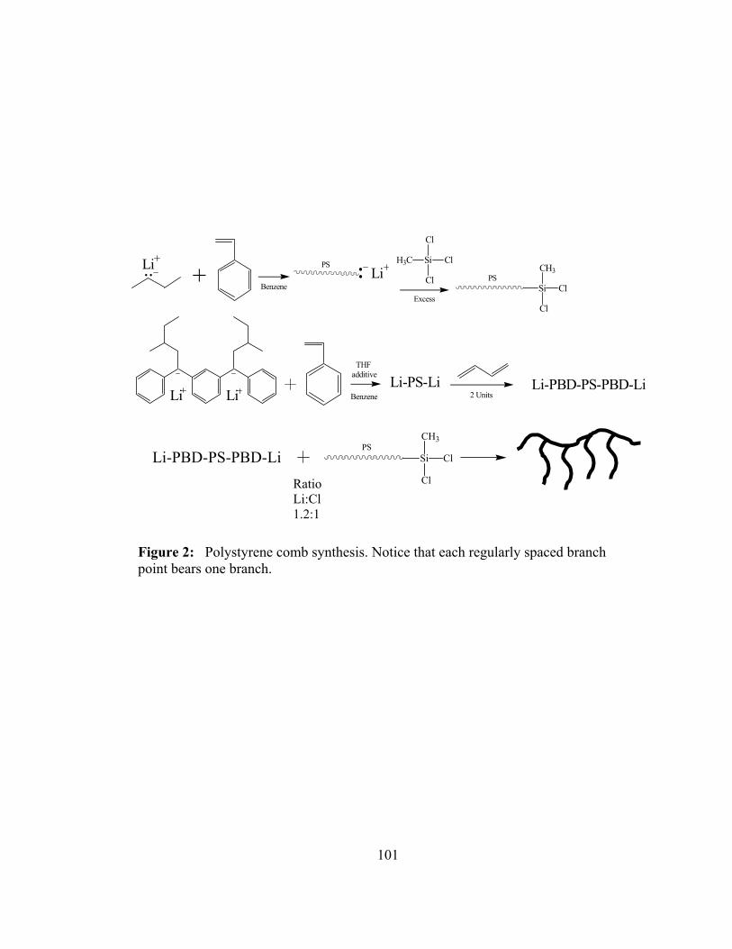
101
Li PSLi
Si
Cl
H3C Cl
Cl PSSi
CH3
Cl
Cl
+Excess
Benzene
Li-PS-LiLiLi
Li-PBD-PS-PBD-Li2 Units
THF additive
Benzene
Li-PBD-PS-PBD-LiPS
Si
CH3
Cl
ClRatioLi:Cl1.2:1
Figure 2: Polystyrene comb synthesis. Notice that each regularly spaced branch point bears one branch.

102
Table 1: Molecular characteristics of the branched polystyrenes
r = (Mside/Mcon) CS = Comb polymer g = Centipede polymers Mcon = Mconnector
0.24 57000 13500 g60-15
0.70 41200 28800 g40-25
2.19 15700 34400 g15-35
1.52 23100 35100 CS25-35
r Mcon. Mside

103
0.80
0.90
1.00
1.10
1.20
1.30
1.40
1.50
1.60
4.90 5.10 5.30 5.50 5.70 5.90 6.10
LOG MW
LOG
RH
/ nm
g60-15
g40-25
g15-35
CS25-35
Linear PS
R H = .00196M.714
R H = .0180M.539
R H = .00596M.616
R H = .0313M.498
R H = .0190M.544
Figure 3: Comparison of the dependence of hydrodynamic radius on molecular weight range for different architectures in a good solvent (THF). g60-15 = ∆, g40-25 = +, g15-35 = *, CS25-35 = ◊, Linear PS = .

104
1.400
1.500
1.600
1.700
1.800
1.900
2.000
2.100
2.200
2.300
2.400
4.700 4.900 5.100 5.300 5.500 5.700 5.900 6.100
LOG MW
LOG
[η]
g60-15
g40-25
g15-35
CS25-35
Linear PS
[η ] = .0638M.568
[η ] = .192M.470
[η ] = .504M.375
[η ] = .138M.494
[η ] = .0121M.718
Figure 4: Dependence of intrinsic viscosity on molecular weight for different architectures in a good solvent (THF). g60-15 = ∆, g40-25 = +, g15-35 = *, CS25-35 = ◊, Linear PS = .

105
0.80
0.90
1.00
1.10
1.20
1.30
1.40
4.50 5.00 5.50 6.00 6.50
LOG MW
LOG
RH
/ nm
g60-15
g40-25
g15-35
CS25-35
Linear PS
R H = .0108M.553
R H = .0493M.429
R H = .0466M.430
R H = .0328M.465
R H = .0409M.451
Figure 5: Dependence of the hydrodynamic radius on molecular weight for different architectures in a theta solvent (trans-decalin). g60-15 = ∆, g40-25 = +, g15-35 = *, CS25-35 = ◊, Linear PS = .

106
Table 2: ε values for regular and random combs and regular centipedes
Polymer ε Values Reference Regular comb 0.8-0.9 This work
Random comb 0.9-1.1 Hadjichristidis et al.[23]
Random comb 0.7-1.0 Roovers et al.[24, 25]
Random comb 0.95 Radke and Mueller[14]
Regular centipedes
g60-15 0.7-1.0 This work
g40-25 0.8-0.9 This work
g15-35 0.8-0.9 This work

107
1.50E+23
2.00E+23
2.50E+23
3.00E+23
3.50E+23
4.00E+23
0.00E+00 2.00E+05 4.00E+05 6.00E+05 8.00E+05 1.00E+06 1.20E+06
MW
Φ
g60-15g40-25g15-35CS25-35Linear PS
Figure 6: Dependence of the Fox-Flory factor Φ on molecular weight. g60-15 = ∆, g40-25 = +, g15-35 = *, CS25-35 = ◊, Linear PS = .

108
Table 3: ρ values for regular and random combs and regular centipedes
Sample ρ (trans-decalin) ρ (THF)
Linear PS 1.13 1.32
CS25-35 1.15 1.04
g60-15 1.23 1.13
g40-25 1.15 1.04
g15-35 1.04 0.96

109
Figure 7: Traditional universal calibration of [η] * M versus retention volume. g60-15 = ∆, g40-25 = +, g15-35 = *, CS25-35 = ◊, Linear PS = .
6
6.5
7
7.5
8
8.5
11.7 12.2 12.7 13.2 13.7 14.2
V R
LOG
[η] *
M
g60-15g40-25g15-35CS25-35Linear PS

110
Figure 8: Universal calibration based on log radius of gyration versus retention volume in the good solvent (THF). g60-15 = ∆, g40-25 = +, g15-35 = *, CS25-35 = ◊, Linear PS = .
1.00
1.10
1.20
1.30
1.40
1.50
1.60
1.70
11.5 12 12.5 13 13.5 14V R / ml
LOG
Rg
/ nm
g60-15g40-25g15-35CS25-35Linear PS

111
Figure 9: Universal calibration based on log hydrodynamic radius versus retention volume in the good solvent (THF). g60-15 = ∆, g40-25 = +, g15-35 = *, CS25-35 =
0.90
1.00
1.10
1.20
1.30
1.40
1.50
1.60
11.7 12.2 12.7 13.2 13.7 14.2 14.7V R / ml
LOG
RH
/ nm
g60-15g40-25g15-35CS25-35Linear PS

112
Figure 10: Universal calibration based on log radius of gyration versus retention volume in the theta solvent (trans-decalin). g60-15 = ∆, g40-25 = +, g15-35 = *, CS25-35 = ◊, Linear PS = .
1.100
1.150
1.200
1.250
1.300
1.350
1.400
1.450
1.500
1.550
11.5 12 12.5 13 13.5
V R / ml
LOG
Rg
/ nm
g60-15g40-25g15-35CS25-35Linear PS

113
Figure 11: Universal calibration based on log hydrodynamic radius versus retention volume in the theta solvent (trans-decalin). g60-15 = ∆, g40-25 = +, g15-35 = *, CS25-35 = ◊, Linear PS = .
0.80
0.90
1.00
1.10
1.20
1.30
1.40
11 11.5 12 12.5 13 13.5 14 14.5 15
V R / ml
LOG
RH
/ nm
g60-15g40-25g15-35CS25-35Linear PS

114
Part 4
Synthesis and Characterization of Polyhedral Oligomeric
Silsesquioxanes (POSS) containing Star Polymers

115
Introduction
Nanotechnology, as defined by K. Eric Drexler in Engines of Creation, is
“technology based on the manipulation of individual atoms and molecules to build
structures to complex, atomic specifications.” [1] Nanotechnology has become a buzz
word in the science world because of the opportunities in research funding that have
become available in recent years. According to Phillips and co-workers, the scientific
community has not reached the true nanotechnology age and refers to the science being
performed currently as nanoscience.[2] With time, nanoscience has branched into more
specific studies, one of which is the nanomaterial science field; this includes the study of
polymer inorganic/organic hybrids. Inorganic/organic hybrid polymer systems were first
made shortly after the first polymers were synthesized. Initially, these hybrid materials
were simple blends of organic polymers that were mixed with inorganic clays. DuPont
was one of the early developers of hybrid materials; they blended polyamide 6,6 with
wollastonite clay.[3] The main driving force behind development of hybrid materials is
the increasing demands of polymers that are synthesized today. Polymers are expected to
exhibit excellent processability, toughness, and optical properties. On the other hand,
several of the big disadvantages of polymers are lower thermal and oxidative stabilities
than inorganic materials. This is the gap that polymer inorganic/organic hybrids bridge.
The current demand is for polymers that excel in all of the categories listed
above.[4] Current research is not only directed towards discovering materials with
thermal and oxidative enhancements, but it is also directed towards advancement of
optical and electronic properties of polymers.[5, 6] In recent years, the advance of these

116
blends have been largely based on incorporated nanoparticles. This is important to
reduce the problems associated with previously studied hybrid materials. When
incorporating large scale inorganic materials, blends were hard to compatibilize and the
properties that make the polymers important were drastically reduced. An example of
problems that arise can be seen in the following example. Polyamide 6,6 blended with
clay at 40% exhibits an increase in tensile strength but a very large decrease in
elongation.[3] It is important to notice this is causing an embrittlement of the polymer.
By shrinking the size of the inorganic domains in the polymer matrix, these defects can
be overcome because of the generation of large interfacial areas which allow better
compatibilization of the material. The dimensions of the weakest link of the material, the
inorganic clay, can now be reduced to allow interaction of the inorganic compound and
the matrix polymer on a molecular level. Not only does making the filler particles
smaller enhance the properties that are being explored, but chemically bonding the
inorganic component to the polymer, through such methods as copolymerization, can also
aide compatibilization. The effect of compatibilization is not only to improve mechanical
properties, but also to improve the optical properties of the materials in question.
Another area being explored with great fervor with respect to the
inorganic/organic hybrid system is the idea of incorporating polyhedral oligomeric
silsesquioxane (POSS) into organic polymers. This area of research has gained a great
deal of expansion over the last ten years due to the availability of POSS on a larger scale.
Hybrid Plastics has opened a plant that has reduced the cost of POSS macromonomers
from $5,000 - $10,000 a pound to $50 -$2,000 a pound.[2]

117
The term silsesquioxane “refers to all structures with the empirical formulas
RSiO3/2 where R is hydrogen or any alkyl, alkylene, aryl, arylene or organo-functional
derivatives of alkyl, alkylene, aryl, or arylene groups.”[7] These silsesquioxane can take
many shapes, random structures, ladder structures, cage structures, and partial cage
structures. The structure of interest in this study is a cubic POSS with a T8 cage
structure. The R group on the POSS may be substituted with many different organic
molecules including methyl groups, phenyl groups, or almost any other organic
functionality.
In previous work, the POSS cubes have been incorporated into many different
polymer materials. The cubes have then been shown to act as initiators, linking agents,
and terminating agents. R group substitution of the POSS allows nearly endless materials
to be created and explored. POSS macromonomers have been incorporated into
polymers using a variety of polymerization techniques including anionic and free radical
methods. [8-15] The focus of this work was an anionic polymerization of star polymers
with POSS as the core linking agent.
The incorporation of POSS into polymer materials provides the means to create
composite polymeric materials that are strong and tough, but also display a greatly
increased thermal stability. While increased thermal stability can be achieved with other
inorganic fillers, POSS is noteworthy because of the ability to chemically bond the
inorganic and organic polymer material together through the use of POSS
macromonomers. This overcomes the common problem of weak polymeric hybrid
systems often encountered with other inorganic fillers due to the low compatibilization of
the organic and inorganic material. One method of incorporating the POSS cube into
118
polymers, is the functionalization of a monomer before the polymerization process with a
functionalized POSS cube. This process is usually carried out via corner capping POSS-
trisilanols with trichlorosilane coupling agents containing a polymerizable group. These
types of reactions usually succeed in greater than 90 percent yield.[16, 17] Incorporation
of the POSS macromonomers for creating the organic/inorganic hybrid materials is
constructive for several reasons:
• Increased solubility of POSS cube in organic solvents
• Increased thermal stability of organic monomers
• The ability to utilize varying polymerization techniques
• Incorporation of small mole percentage of POSS macromonomer results in large
weight percentage of POSS in hybrid material
• Increased resistance to oxidation
• Reduced flammability
• Large size of POSS, ~1.5 nm, with a cyclopentyl or cycylohexyl substituent
POSS macromonomers have been incorporated into many different copolymer systems.
Examples of copolymers that have been synthesized include Styrl-POSS, Methacrylate-
POSS, and Norbornyl-POSS copolymers, just to name a few.[8, 17, 18]
Haddad and coworkers were some of the first to form a copolymer of POSS
macromonomers and 4-methylstyrene using a POSS-styryl macromonomer
(POSSSM).[19] They also explored the properties of the homopolymers of POSSSM
with varying R groups on the POSS cube. They studied both a cyclopentyl and a
cycylohexyl group R substitution. They found very different solubilities between the two

119
copolymers, with the cyclopentyl substituent significantly reducing the solubility of the
homopolymer in THF by more than order of magnitude when compared to the
cycylohexyl substituted monomer. While exploring the copolymer of POSSSM and 4-
methylstyrene, they varied the amount of POSSSM loading to monitor the thermal
properties of the copolymer. They found loads greater than 20% POSSSM resulted in no
discernable glass transition for the copolymer by DSC measurement. They also noted the
degradation temperature of the copolymer increased linearly with the amount of
POSSSM that was loaded into the copolymer.[19] Their hypothesis to explain this
phenomenon was that the POSS was aggregating and forming a type of thermoplastic
hybrid material.
Researchers at the Air Force Research Laboratory also conducted experiments on
how the substituent on the POSS cube macromonomer affected the thermal properties of
copolymers formed from them. Experiments were carried out on copolymers of 4-
methylstyrene and 30% by weight POSSSM that contained four different substituents;
isobutyl, cyclopentyl, cycylohexyl, and phenyl groups. These copolymers were subjected
to dynamic mechanical testing and were determined to have higher mechanical strengths
then the homopolymerized 4-methylstyrene at 30°C above the glass transition
temperature of the poly(4-methylstyrene). The cyclopentyl and cyclohexyl substituted
POSS groups exhibited the highest mechanical strengths, with a storage modulus over
106 Pa and almost an order of magnitude higher than the homopolymerized poly(4-
methylstyrene when compared above the glass transition temperature. The phenyl
substituted material was not able to be compared effectively because of solubility issues
that arose during the polymerization process.[18] Due to the solubility issues that arise in

120
this particular study phenyl substituted POSS will not be used in the polymers proposed
in this proposal.
The first group to report a thermoplastic elastomer from these POSS nanoparticles
was Coughlin and coworkers at the University of Massachusetts, Amherst. They found
that by combining cyclooctadiene with a cyclopentyl-POSS macromonomer they could
generate a random butadiene/POSSSM copolymer via a ring opening metathesis reaction.
The elastic properties increased with POSS loading in the copolymer, with a 40% by
weight copolymer exhibiting the best toughness properties at 100% strain.[16] The
Coughlin group went on to further study why there was an increase in the mechanical
properties of these copolymers. Through transmission electron microscopy (TEM), wide
angle x-ray diffraction (WAXD), and small angle x-ray scattering (SAXS), they observed
the morphologies of the copolymers and found the copolymers self assembled into
ordered microstructures. The POSS cubes preferentially aggregated to form sheets of
POSS cubes that crystallize into an ordered lattice. The sheets were found to vary with
varying amounts of POSS loading; at low loading, the sheets were distributed randomly
through out the polymer and at higher concentrations, continuous lamella were seen
throughout the samples. A key point to note is that it was shown that these lamellar
structures were formed from random copolymers that had large polydispersities. This is
an unusual occurrence when observing self-assembled morphologies of copolymers.
Well defined block copolymers are generally required to observe these types of
nanostructures.[20]
For these types of materials to obtain the high thermal stabilities necessary for
many industrial applications, it is useful for the organic part of the hybrid material to be a

121
polymer that is more stable than polybutadiene; thus, a synthetic route to a polyethylene
(PE)-POSS copolymer was developed.[9] The PE-POSS copolymers that resulted were
random in nature, as were the polybutadiene-POSS copolymer mentioned earlier. These
types of polymers exhibited even better thermal properties than that of the butadiene
copolymers. The onset degradation temperature of these polymers is 437°C or greater
depending on the POSS loading, more than 100°C higher than that of polybutadiene
copolymers with comparable POSS loading.[21]
An inconvenience brought on by using PE in the copolymer system is that linear
PE is a highly crystalline polymer. Further research on these types of polymers has
revealed that the crystallization of PE reduces the ability of the POSS cubes to
aggregate.[22] The amount of POSS aggregation within the PE-POSS copolymers was
found to be very dependent on sample preparation. The amount of POSS aggregation
was compared with two different sample preparation methods; melt crystallization and
crystallization from hot xylene using X-ray diffraction. During solution crystallization,
the POSS cube is restricted to aggregate with only other nearby POSS units, as a direct
result of the crystallized PE chains forming a lattice structure locking the POSS cubes in
place. This results in a material that has very few, and consequently, smaller POSS
lamella. The melt crystallized material, however, shows a large crystalline peak in the X-
ray diffraction pattern when compared to the solution crystallized material. When
comparing the thermal stabilities of the two materials, a large difference can be seen
between the two different sample preparation methods. The difference in the onset
degradation temperature from one material to another is significant; the melt crystallized
sample has a higher onset degradation temperature by as much as 200°C. This proved

122
that even for the same sample, processing conditions play a huge role in the final
copolymer properties.[22]
The previous inorganic/organic hybrids discussed earlier involved a grafting
method or a copolymerization of a organic monomer with a modified POSS monomer.
Star polymers have been synthesized by two different methods. POSS can be used as a
functional initiator and the arms of the star can be polymerized from the POSS core. Kim
and coworkers refer to this method as the “core first method”. They modified the POSS
cubes with various initiating agents for ring opening metathesis polymerization (ROMP).
They found that using POSS cube initiation to polymerize 2-methyl-2-oxazoline was
inefficient. At most only 4 to 5 of the arms were activated and consisted of varying
molecular weights. They propose that steric hindrance plays an important factor in the
initiation of the star core. Each corner of the cube may have an individually different
initiation rate. [23] They also concluded that the amount of POSS incorporated into the
polymer had significant effects on the thermal properties of the polymer. For example,
the more POSS the better the thermal degradation temperature and a smaller transition
was recorded for DSC. With a monomer to cube-initiator ratio greater than 200 to 1 no
significant changes in thermal properties were observed.
Stars using the “core first method” were also attempted by Costa, Laine, and
coworker. They attempted to synthesize star polymers using atom transfer radical
polymerization (ATRP). The reactions were varied by trying to optimize the POSS
modified ATRP initiator. They attached 2-bromo-2-methylpropionoxy
propyldimethylsioxy to a silsesquioxane cube to form octakis (2-bromo-2-
methylpropionoxy propyldimethylsioxy) octasilsesquioxane (OBPS). The bromo

123
initiator core was used in conjunction with the copper catalyst CuCl to polymerize methyl
methacrylate. Well defined stars were not synthesized by any of the methods they
developed. Termination reactions between stars, combined with inefficient initiating
sites from all 8 corners of the POSS cube contributed to inefficient star formation. They
determined that the best efficiency achieved was 7 arms, but that 6 arms were more likely
to form. They also confirmed that using GPC to monitor the process creates a problem
because the resulting star polymer will have a smaller hydrodynamic volume compared to
its linear counterparts making characterization difficult with conventional GPC. The
polydispersities obtained using ATRP were also higher than for typical ATRP reactions.
The typical polydispersities achieved by this polymerization method are usually 1.1-1.2.
Such dispersities were not observed in these polymerizations. Although they did not
report specific values for the polydispersity, the GPC traces show several very different
molecular weight species present in all of their polymerizations.[24]
Due to limitations using the “core first method” of generating star polymers, a
“grafting onto” method was developed. The experimental section describes how
polybutadiene was polymerized using anionic techniques and grafted onto a POSS cube
that was modified with a chlorosilane moiety. The “grafting onto” method provides a
route to well defined arms that can be characterized before the star is made. The
characterization of the star once the linking process takes place provides insight into the
linking procedure.

124
Experimental
Synthesis The 8 arm star polymers were synthesized using anionic polymerization
techniques coupled with modified chlorosilane linking agents. Linear polybutadienes of
varying molecular weight were synthesized and characterized by GPC coupled with
online light scattering. The dn/dc value used to calculate the molecular weight from light
scattering was 0.130 mL/g in THF at 40 oC. The living polybutadienes were sealed in
glass ampoules and set aside for use during the coupling process.
The linking agent was synthesized from a POSS derivative. Figure 1 (all Figures
will be in the appendix of this section) shows the structure of the POSS starting material.
Each corner of the POSS cube has been capped with a (CH3)3Sn-O- group. The Tin
modified POSS (SnPOSS) cube was obtained from the labs of Dr. Craig Barnes at the
University of Tennessee and had been characterized by NMR. The POSS cubes need to
be sealed in glass ampoules to be used in combination with the anionic synthesis
technique. First the POSS cube was dissolved in a small amount of unpurified THF
obtained from Fisher Scientific. The solution was injected into an apparatus shown in
Figure 2 through a side arm located on the side of a round bottom flask. The side arm
was capped with a rubber septum and the apparatus was placed on a high vacuum line.
The THF was slowly pumped off to avoid bumping of the material in the flask. Once the
THF is removed and the vacuum is completely open to the apparatus, the side arm that
was used to inject the material is heat sealed using a glass blowing torch. The SnPOSS
must undergo a drying process to remove water which can bind to the POSS derivative.

125
The flask is heated in a silicone oil bath for 24 hours at 100oC under vacuum to remove
water.
After drying on the vacuum line, a known amount of purified THF is distilled into
the apparatus to generate a known molarity for use during the linking process. The THF
was purified in the same manner as that for anionic polymerization in THF. The THF is
initially dried over CaH2 which is degassed three times and allowed to stir overnight. The
THF is then distilled over a sodium/potassium alloy which is made from 3 to 1 mixture of
sodium to potassium (NaK) which is liquid at room temperature. This mixture undergoes
three freeze/thaw degas cycle, and allowed to stir until a light blue color is observed.
The purification of the THF is essential to ensure there are no impurities which would
terminate the living polymer chains. Once the known amount of THF is distilled into the
apparatus the entire apparatus is heat sealed from the vacuum line and put aside.
Distilling a known amount of THF into the apparatus allows a concentration of cubes in
solution to be calculated. Consequently the required amount of POSS cube for a given
reaction can be measured and take from the apparatus.
The chlorosilane used in this reaction was dichlorodimethylsilane >99.5% pure
obtained from Aldrich. The chlorosilane was purified by stirring over CaH2. The
mixture was degassed once with a freeze/thaw cycle and then allowed to stir for 24 hours.
It was then degassed three times after the 24 hour period. When purchasing the
chlorosilane it is notable to buy small bottles, usually the 100 ml or 100 gram bottles.
This is recommended because of the highly reactive chlorosilane which can undergo
protoylsis with water. Use of an entire bottle during the purification process will help
ensure the purity of the distilled reagent. When distilling the purified reagent the first

126
third of the distillation is discarded. The middle third is distilled to ampoules and heat
sealed under vacuum. The final third is also discarded. This method is used to ensure the
chlorosilane being distilled has the functionality that we desire.
Careful consideration must be used when making the linking apparatus. The
apparatus can be detached from the vacuum line during the modification process or the
reactor may stay attached. If the first option is used an additional break-seal and
constriction are necessary to allow reattachment to the vacuum line. A photograph of the
type of apparatus used in this synthesis is shown in Figure 3. The apparatus contains
living polybutadiene, methanol, dichlorodimethylsilane, and an ampoule of pre-measured
SnPOSS diluted with THF. The entire apparatus was assembled and attached to the high
vacuum line.
Once the vacuum has pumped down to an acceptable level and tested with the
Tesla coil, the system is closed by shutting the stopcock which connects the system to the
vacuum line. The ampoule containing the dichlorodimethylsilane is broken and the
liquid is stirred by the glass encased magnet present in the system. The modified POSS
cube dissolved in the THF ampoule is then broken and allowed to mix with the
chlorosilane through a finger tip entry to ensure the POSS cube is added directly to the
chlorosilane. The order of the addition is important to try to prevent crosslinking of the
cube. A large excess of the chlorosilane was used in this addition never smaller than 100
times the molar amount needed. Ideally it would be advantageous to add the POSS-THF
solution drop wise to allow the system to react, but because the system is under vacuum
and the vapor pressure of the chlorosilane is so low, this type of addition is not
accessible. The reaction scheme is shown in Figure 4. This reaction was allowed to
127
proceed for two hours before the excess dichlorodimethylsilane and chlorotrimethyltin
were distilled out of the system. The system was again introduced to the vacuum and
heated by a water bath at 80oC for 24 hours.
The vacuum quality was again tested at the end of the 24 hours with the Tesla coil
to ensure that all of the excess chlorosilane and tin byproduct were removed from the
system. Once the applied vacuum was sufficient, the entire system was heat sealed from
the vacuum line and the living polymer solution was added to the modified chlorosilane
cube. This can be seen in Figure 5. Subsequent samples were taken to follow the
reaction progress through small sampling ampoules attached to the reaction vessel. In
each reaction mixture the amount of living polymer added to the POSS cubes was in
excess by 20% excess to facilitate the star formation. The reaction was followed with
GPC to confirm the linking process. Once the linking was completed the excess linear
material was terminated with methanol. The material was isolated in an excess of
methanol and a small amount of butylated-hydroxytoluene was added to prevent
oxidation of the polybutadiene. The remaining mixture was fractionated using the
solvent/nonsolvent pair of toluene/methanol.
Once the star polymer was fractionated the polymer was dried in a vacuum oven
at room temperature to prevent oxidation of the polymer. The polymer was dried until
the resulting polymer was transparent and there was no cloudiness left in the bulk
material.

128
Characterization
GPC analysis was used to monitor the linking process in conjunction with online
light scattering measurements. The polymers that were synthesized are shown in Table 1.
The first polymer of interest is the polybutadiene polymer that has been end capped with
polystyrene. This particular polymer was synthesized by polymerizing a homopolymer
of polybutadiene then adding 4 units of polystyrene to the end of the living chain. The
end capping of the polymer was achieved by using a ampoule of styrene that had been
diluted with hexanes to a lower concentration so an appropriate amount of styrene could
be added to the living polybutadiene. Living polybutadiene will not efficiently initiate
styrene without the presence of a polar additive, so a small amount, less than 1 ml of THF
was added to the system to assist in the polymerization of the styrene. In Figure 6, the
GPC of the end capped polystyrene is shown. The figure shows the grafting reaction
after 45 days of linking. This GPC trace did not differ much from the grafting reaction
after one week progress. The styrene capped polybutadiene generates a sterically
hindered attacking group. Due to the sterics of the linking reaction the eight arm star is
never formed. At most 6 arms are achievable. The other species present in the GPC are
due to termination of the living chain end over time to the exposure of THF. The
molecular weights of the peaks were obtained by GPC with online light scattering.
Demonstration of the limiting effects of the end group on the living polymer may provide
routes to synthesizing mikto star type material. It may be useful to compare a polystyrl
anions to a diphenylethylene (DPE) anions to monitor how steric interactions affect the
linking reaction.

129
In Figure 7, the effect of having a small living chain end, as is the case with a
polybutadiene anion, is that the linking reaction takes place very quickly. It is not
necessary to use a polar additive such as THF to assist in the breaking of the lithium
anion aggregates. It is also important to note that the linking process is one hundred
percent efficient; there were no star species that had arm numbers between one and the
fully grafted 8 arm POSS derivative. This was verified with the online light scattering
instrument. This efficient linking leads to star polymers that are easy to fractionate from
the starting material because the molecular weight difference between the starting
product and the final star differs so greatly.
The linking of the sample of PBD20 with MW ~20,000 g/mol was also
characterized by GPC with online light scattering. Figure 8 shows the resulting polymer
after the fractionation procedure was performed to remove the excess material. This
particular GPC chromatogram is interesting because of the high molecular weigh peaks
that are present. The peaks are notably visible in the light scattering detectors and barely
detectable in the refractive index detector. The resulting peaks correspond to the 14 and
20 arm star polymers that would be formed due to the fact that some of the POSS
material cross linked when the dichlorosilane material was added to the flask containing
the tin modified POSS. The crosslinking reaction that would occur is when one
dichlorodimethylsilane unit reacts with two SnPOSS cubes this in effect would generate a
cross linked POSS core. The POSS core would contain 14 active chlorosilane sites
where polymer arms could attach since one corner of each cube would be used in the
linking of the two cubes. The 20 arm star variety would occur if this cross linking would
occur between three SnPOSS cubes during the chlorosilane capping step. Since each

130
cube has 8 active sites the middle cube in effect lose two sites due to cross linking while
the outer POSS cubes would each lose one active site. The affect is that instead of having
24 active sites there would only be 20 active chlorosilanes sites to link the arms.
The refractive index is directly proportional to the amount of material that is
present in solution; therefore, the amount of cross linked material is minuscule.
However, because the molecules are so large, even at such a low concentration the light
scattering intensity is significant enough to measure the molecular weights of the elution
peaks from the GPC.
The effect of the POSS starting material on crosslinking is not evident in the
higher molecular weight material. I do not believe that this is because cross linking of
the cube is not occurring. The amount of cross linking of the cube is small but some can
not be avoided. Due to the high molecular weights present in the PBD110 sample good
separation may not be occurring in the GPC columns. The PBD110 sample had a MW of
900,000 g/mol which in effect is covering up the 14 and 20 arm star varieties. The
elution times will not be separated enough in our GPC instrument because the columns
have reached their molecular weight limit. Reexamination of the material with columns
that can handle larger molecular weights should verify this hypothesis.
The lower molecular weight sample was prepared to run NMR studies of the
POSS cube and oligomeric polybutadiene chains. An attempt to synthesize this material
proved to be challenging. The polydispersity of the arm material proved to be very broad
because of the small molecular weight that was attempted to be synthesized. Since the
distribution of the starting material was broad, tracking the linking process was
impossible. The SEC chromatogram of the oligomeric 8 arm star material was very

131
broad, and also the amount of cross linking between the cubes would have increased
because the molar amount of cube would have been greater in this reaction. Isolation of
the final product proved to be difficult because the final material was slightly soluble in
methanol, this may be due the ratio of inorganic to organic material present in this low
molecular weight sample.
Two samples PBD20 and PBD110 were isolated as star material were analyzed by
differential scanning calorimetry (DSC) and thermal gravimetric analysis (TGA). The
star polymers that had POSS incorporated as the linking agent, showed no significant
increase in thermal properties. The glass transition temperature of the hybrid material
was similar in nature to that of homo-polybutadiene. The glass transition temperature of
both star materials was ~ -90oC which is in agreement with literature values. Subsequent
DSC experiments were run with 3 heating cycles to 250 degrees with slow cooling to
monitor if any aggregation of the POSS cube was occurring. No transition was ever
observed in either sample. This effect is not surprising due to the low amount of POSS
cube that is incorporated into the hybrid material.
TGA of the PBD20 and PBD110 in an air atmosphere and nitrogen atmosphere
proved the same conclusions that as from the DSC. Not enough POSS was incorporated
into the hybrid material to see any difference in the behavior of the homo-polymer
material to that of the hybrid material. Figure 9 shows the TGA of sample PBD110 in
each TGA experiment.
The calculated amount of POSS mol% in star samples PBD20 and PBD110 are
theoretically 0.033 % and 0.0061 % mol percent respectively. The theoretical weight
percent of the two samples is 0.33 wt% and 0.061 wt% respectively. This low

132
incorporation of POSS is not enough to provide adequate physical property change.
Results have been reported that a minimum of 10% by weight and 1.4 mol % of POSS is
necessary to induce changes in the physical properties of the polymer.[16, 19, 25]
Therefore the results for the polymers synthesized were not surprising.
Future Work
To our knowledge this is the first report of POSS cubes to be utilized as a linking
agent using anionic polymerization. These preliminary reactions show promise in using
this material in the future of anionic polymerization. The POSS cube could be modified
with other chlorosilanes to access larger armed structures. Using trichlorosilanes or
tetrachlorosilanes would lead to 16 and 24 arm linking agents. Also utilizing these
chlorosilane modified POSS in conjunction with anionic polymerizations could lead to
interesting cross linked material. The use of this type of chemistry opens a door to a
variety of polymer structures that are only available through anionic techniques such as
mikto arm stars and possible barbed wire structures with POSS at the core of the material.
Also as a way to incorporate more POSS into the polymers, it may be useful to
larger POSS moiety such as the penta-cube structure, or crosslink several POSS cubes to
create a larger central core unit therefore incorporating more POSS into the polymer
composite. The physical properties of the inorganic/organic hybrids should benefit from
the use of the anionic technique so the exact amount of POSS needed to enhance physical
properties can be explored more in depth.
Conclusions
A novel anionic star polymer synthesis was developed to incorporate POSS into
the core of the star material. The linking reactions were achieved by modifying SnPOSS

133
cubes and reacting them with dichlorodimethylsilanes. In this work polybutadiene was
utilized as the main arm material in all of the star synthesis. We have shown that by
incorporating large monomers into the living chain, the rate of reaction of the linking can
be modified. The incorporation of polystyrlanions on the polybutadiene significantly
slowed and prohibited the numbers arms that could be attached to the POSS cube. The
linking time for the polymers with the larger polystyrene unit was allowed to proceed for
over 40 days with out full linking of the arm material; whereas, the linking time in the
pure polybutadiene material was fully linked in three days for the PBD20 sample and the
PBD110 sample. The linking reaction kinetics is severely limited by the size of the
monomer unit of the living anion. The molecular weight of the arm material also has an
effect on the amount of possible attacking chain ends but a 20% excess is enough to
overcome the dilution effect of the linking process. Limited control may be incorporated
by providing a sterically hindered end group to the living polymer chain end.
The fact that there was no increase in degradation temperature was not surprising,
as an insufficient amount of POSS was used. POSS loading of higher than 10% by
weight are usually necessary for enhanced thermal properties, based on the literature.
Large weight percent are easily achievable at very low mole percent loadings as is
evident in the calculations from our samples. Other mechanical properties, such as
increases in the tensile strength are seen at much lower POSS incorporations.

134
References

135
1. Drexler, K. E., Engines of Creation The Coming Era of Nanotechnology Anchor Books: New York, 1986.
2. Phillips, S. H.; Haddad, T. S.; Tomczak, S. J. Current Opinion in Solid State and Materials Science 2004, 8, (1), 21-29.
3. Nielsen, L. E., Predicting the Properties of Mixtures: Mixture Rules in Science and Engineering. Dekker: New York, 1978.
4. Schwab, J. J.; Lichtenhan, J. D. Applied Organometallic Chemistry 1998, 12, (10-11), 707-713.
5. Sanchez, C.; Lebeau, B.; Chaput, F.; Boilot, J. P. Advanced Materials 2003, 15, (23), 1969-1994.
6. Herron, N.; Thorn, D. L. Advanced Materials 1998, 10, (15), 1173-1184.
7. Baney, R. H.; Itoh, M.; Sakakibara, A.; Suzukit, T. Chem. Rev. 1995, 95, 1409-1430.
8. Pyun, J.; Matyjaszewski, K. Chem. Mater. 2001, 13, (10), 3436-3448.
9. Zheng, L.; Farris, R. J.; Coughlin, E. B. Journal of Polymer Science Part A: Polymer Chemistry 2001, 39, (17), 2920-2928.
10. Matyjaszewski, K.; Miller, P. J.; Fossum, E.; Nakagawa, Y. Applied Organometallic Chemistry 1998, 12, (10-11), 667-673.
11. Lichtenhan, J. D.; Otonari, Y. A.; Cam, M. J. Macromolecules 1995, 28, 8435-8437.
12. Matyjaszewski, K.; Miller, P. J.; Pyun, J.; Kickelbick, G.; Diamanti, S. Macromolecules 1999, 32, (20), 6526-6535.
13. Choi, J.; Yee, A. F.; Laine, R. M. Macromolecules 2003, 36, (15), 5666-5682.
14. Ohno, K.; Sugiyama, S.; Koh, K.; Tsujii, Y.; Fukuda, T.; Yamahiro, M.; Oikawa, H.; Yamamoto, Y.; Ootake, N.; Watanabe, K. Macromolecules 2004, 37, (23), 8517-8522.
15. Lee, H. C.; Chang, T.; Harville, S.; Mays, J. W. Macromolecules 1998, 31, (3), 690-694.
16. Zheng, L.; Farris, R. J.; Coughlin, E. B. Polymer Preprints 2001, 42, (2), 885-886.

136
17. Li, G.; Wang, L.; Ni, H.; Pittman, C. U. Journal of Inorganic and Organometallic Polymers 2001, 11, (3), 123-154.
18. Haddad, T. S.; Viers, B. D.; Phillips, S. H. Journal of Inorganic and Organometallic Polymers 2001, 11, (3), 155-164.
19. Haddad, T. S.; Lichtenhan, J. D. Macromolecules 1996, 29, (22), 7302-7304.
20. Zheng, L.; Hong, S.; Cardoen, G.; Burgaz, E.; Gido, S. P.; Coughlin, E. B. Macromolecules 2004, 37, (23), 8606-8611.
21. Zheng, L.; Farris, R. J.; Coughlin, E. B. Macromolecules 2001, 34, (23), 8034-8039.
22. Waddon, A. J.; Zheng, L.; Farris, R. J.; Coughlin, E. B. Nano Lett. 2002, 2, (10), 1149-1155.
23. Kim, K.-M.; Ouchi, Y.; Chujo, Y. Polymer Bulletin 2003, 49, 341-348.
24. Costa, R. O. R.; Vasconcelos, W. L.; Tamaki, R.; Laine, R. M. Macromolecules 2001, 34, 5398-5407.
25. Tomczak, S. J.; Marchant, D.; Svejda, S.; Minton, T. K.; Brunsvol, A. L.; Gouzman, d.; Grossman, E.; Schatz, G. C.; Troya, D.; Sun, L.; Gonzalez, R. I. Materials Research Symposium 2005, 851, (1), 395-406.

137
Appendix

138
O(H3C)3Sn
Si O Si
O
Si O Si
O
O
Si O Si
O
Si
O
O
Si
O
O
O
O
O
O
OO
O
(H3C)3Sn Sn(CH3)3
Sn(CH3)3
Sn(CH3)3(H3C)3Sn
(H3C)3Sn
Sn(CH3)3
Figure 1: The tin modified POSS cube.
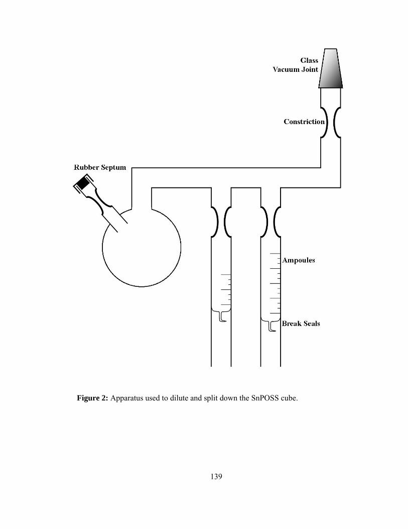
139
Figure 2: Apparatus used to dilute and split down the SnPOSS cube.

140
Figure 3: Linking apparatus used to make the star polymers containing POSS at the core.

141
Si O Si
O
Si O Si
O
O
Si O Si
O
Si
O
O
Si
O
O
O
O
O
O
O
O
O
O
(H3C)3Sn
(H3C)3Sn
Sn(CH3)3
Sn(CH3)3
(H3C)3Sn
(H3C)3Sn
(H3C)3Sn
Sn(CH3)3 Si
CH3
CH3
ClCl
Sn
CH3
CH3
CH3Cl
Si O Si
O
Si O Si
O
O
Si O Si
O
Si
O
O
Si
O
O
O
O
O
O
O
O
O
O
(H3C)2Si
(H3C)2Si
Si(CH3)2
Si(CH3)2
(H3C)2Si
Si(CH3)2
(H3C)2Si
Si(CH3)2
ClCl
Cl
Cl
ClCl
Cl
Cl
+
100x excess
8x
+Si
CH3
CH3
ClCl
excess
+
Figure 4: Reaction scheme for the modification of the SnPOSS cube before the linking process is performed.
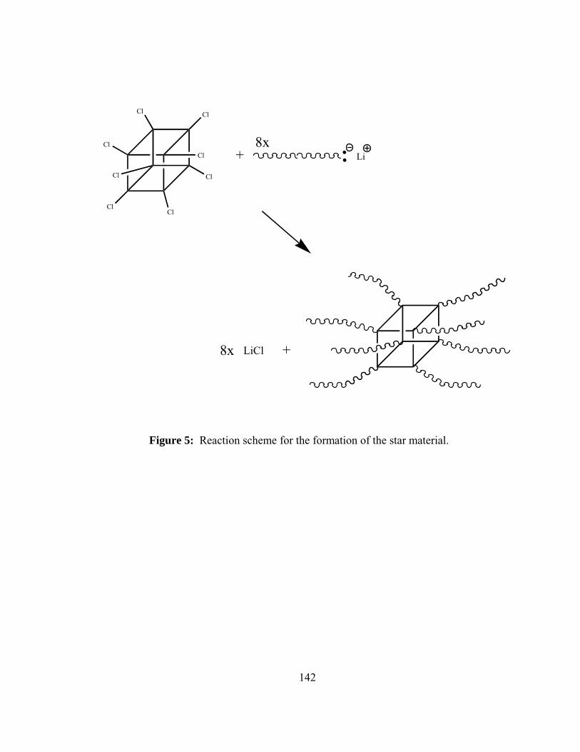
142
ClCl
Cl
ClCl
Cl
Cl
Cl
Li
LiCl
8x+
8x +
Figure 5: Reaction scheme for the formation of the star material.

143
Table 1: Arm molecular weights and star molecular weights of polybutadiene samples.
Polymer Arm MW
PDI Star MW PDI
PS encapped PBD
20K 1.04 Multiple armed material
Disperse
PBD20 21K 1.05 184K 1.04 PBD110 113K 1.03 921K 1.07
PBD small < 1000 Disperse Disperse Disperse

144
PS endcapped PBD linking with POSS 45 days
20.00 21.00 22.00 23.00 24.00 25.00 26.00 27.00 28.00 29.00 30.00
Retention Volume (mL)
Excess Arm
Two Arms Three
Arms Six
Arms
Eight Arms Never
Reached
Figure 6: GPC of grafting reaction after 45 days.

145
PBD110 Linking after 3 days
10 10.5 11 11.5 12 12.5 13 13.5 14 14.5 15
Retention Volume (mL)
Excess Arm
Eight Arm Star
Figure 7: GPC of Polybutadiene 8 arm star after 3 days of reacting

146
8 Arm Star
14 Arm Star 20 Arm Star
Sample PBD20 Arm Linking after Fractionation
Figure 8: GPC of PBD20 and the resulting polymer after fractionation.

147
PBD110 8 arm Star TGA in Air Atmosphere
PBD110 8 arm Star TGA in N2 Atmosphere
Amount of POSS cube incorporated in this sample is less than .1% by weight.
Figure 9: TGA of polybutadiene samples in the presence of air and nitrogen atmosphere.

148
Part 5
Conclusions

149
Anionic polymerization will continue to be a valuable and viable method to
obtain well defined complex polymer architectures. At the time of this dissertation there
is no synthetic method available as versatile as anionic synthesis coupled with classical
high-vacuum glass blowing techniques. There are polymerization methods available that
provide some control such as living free radical and nitroxide mediated polymerizations,
but none offers the control over architectures and polydispersities achievable through the
anionic methodologies.
Chlorosilanes are essential to accessing architectures in anionic polymerization,
but they prove to be capricious chemicals to utilize. Chlorosilanes are useful chemicals;
the purification of the chlorosilanes is the most important step in the synthesis of complex
architectures. It is better to sacrifice portions of the chlorosilane during the purification
rather than try to distill the entire solution of chlorosilane being used. A poorly purified
chlorosilane can ruin months of polymer synthesis, so it is of great significance that
immense care is taken in their purification.
The use of chlorosilanes as linking agents provides some of the most versatile
architectures available when coupled with anionic technique. The chlorosilanes provide
access to star, comb, centipede, and barbwire structures when used in a clean and
impurity free environment. The incorporation of polyhedral oligomeric silsesquioxane
(POSS) provides a new class of chlorosilanes to be explored. At the time of publication
of this dissertation there have been no accounts of POSS coupled with anionic
polymerizations to produce star polymers. In a previous chapter, a novel synthetic route
was described to produce a POSS moiety that contained an 8-arm chlorosilane cube
150
utilizing dichlorodimethylsilane. As is the case in the synthesis of comb and centipede
polymers the POSS cube selectively attacked by living anion depends on the bulkiness of
the living chain end as is demonstrated when end-capping polybutadiene with
polystyrene. The incomplete incorporation of eight arms through this method proves that
sterics play an important role in the linking process.
Also in the dissertation, the synthesis of well defined poly(ethylene-co-
propylene) polymers was successfully carried out for stars with divinylbenzene as the
linking agent. Careful thought should be taken when trying to hydrogenate star polymers
containing chlorosilanes as the core linking agent. The carbon silicon bond was shown to
undergo degradation when exposed to high temperatures and long reaction conditions.
The effect of the hydrogenation conditions on the chlorosilane was proven further by the
fact that no degradation was seen in the PI star containing divinylbenzene as the linking
agent. A milder reaction using Pd/CaCO3 and lower temperatures may provide the route
to better hydrogenation of chlorosilane linked stars and graft polymers.
The characterization of polymers is not an easy task, especially for polymers
with broad molecular weight distributions and unknown amounts of branching. Through
the use of anionic polymerizations and new characterization techniques new models can
be developed to help provide insight into polymers with more exotic structures that are
not easily defined. The characterization of comb and centipede branched polystyrenes
provide the insight into creating better systems for characterizing regularly branched
polymers. The information accumulated about g and g’ and their relationship between
each other by the factor ε leads to better correlation of theory and experimental results. I

151
believe that the work described in this dissertation will allow models of branched
molecules to be improved upon in the future.
Future Work
Through the use of other chlorosilanes such as trichloromethylsilane and
tetrachlorosilane, 16- and 24-arm stars should be able to be synthesized. The
incorporation of POSS into molecules with well defined structures could lead to new and
interesting polymer morphologies. Not only has POSS research opened up new linking
structures, but it also may provide new means to accessing mikto arm star materials due
to the fact that steric hindrance plays in a role in the way a polymer chain reacts with the
each corner of the POSS cube.
Other interesting architectures can be explored using these new chemistries that
are available with the POSS chlorosilane derivatives. Difunctional initiators such as the
ones used to generate the comb and centipede type polymers could be used with the
POSS chlorosilanes to provide routes to new centipedes and combs that incorporate
POSS into the backbone of the material. A possible synthetic route would utilize a
chlorosilane used to form 8-arm star material. The POSS chlorosilane material would
either be reacted with polystyrene (PS) or a polystyrene capped material which would in
turn generate a POSS cube with 6 arms attached to the structure. This would leave two
chlorosilane corners available for reaction. At this point a difunctional initiated polymer
chain of lower steric hindrance could be introduced, such as polybutadiene (PBD), to
generate a barbwire type of architecture. This particular architecture would be of interest
due to the fact that the backbone of the polymer would be PBD with PS grafts and POSS
at the graft points. The morphologies of structures like this could be very interesting, due

152
as similar structures have been studied but without the POSS derivative incorporated into
the polymer architecture.
The use of chlorosilanes has proven to be an effective method for making
mikto arm stars and graft type centipedes and combs. Any of the structures described in
this dissertation or proposed in this conclusion could benefit from the creation of
deuterated polymers. Recent advancements in the availability of neutron scattering
experiments in conjunction with the opening of the Spallation Neutron Source at Oak
Ridge National Laboratory in the near future, provides the opportunity for a plethora of
experiments to be conducted. The replacement of one or more of the polymer arms or
grafts with a deuterated arm or graft could provide insight into how these polymers
behave in solution and in the melt state.
POSS cubes have been incorporated into polymers using a variety of other
methods but the use of anionic polymerization should provide a route of incorporation
that allows for particular insertion of the cube into a polymer. Since the POSS cube has
been proven stable under anionic conditions, use of the POSS cube by means other than
chlorosilanes should be explored. The integration of a polymerizable unit at the corner of
each cube would provide the ability to generate 16-arm stars with 8 arms of one
monomer such as PI and 8 arms of another such as PS. This should be accessible through
the types of chemistry described in modifying the POSS cube. Instead of using a
dichlorosilane, a bromine compound, such as 4-bromo-1-butene could be coupled with
the Sn modified POSS cube to generate the type of POSS derivative needed to synthesize
the type of star polymer described.

153
The types of architectures that were examined by size exclusion
chromatography coupled with online measurements as two angle laser light scattering
(TALLS) and online viscometry were only homopolymers of polystyrene. Investigation
of other polymers of similar structure such as polybutadiene or polyisoprene, could
provide more insight into the dilute solution properties of comb and centipede structures
and the g and g’ values. These polymers if synthesized could later be hydrogenated
through a method described earlier in this thesis and provide details about polyethylene
and poly(ethylene-co-propylene) architectures.
Although the research described in this dissertation has provided some insight
into the synthesis and behavior of some interesting polymer architectures; many different
structures still exist to be explored and many questions still need to be answered.

154
Vita
Brandon Scott Rano Farmer was born in Norfolk, VA on August 22, 1977. He
was raised in Virginia Beach, VA and went to grade school at St. Gregory the Great
School. He graduated from Kempsville High School in June of 1995. In August of the
same year, he went to the University of Montevallo, in Montevallo, AL and received a
B.S. in Chemistry and minor in Mathematics in May of 1999. In 1999, he began the
pursuit of his doctorate at the University of Alabama, Birmingham (UAB) in
Birmingham, AL. In 2002 he performed research at the Ian Wark Research Institute part
of the University of South Australia in Adelaide, Australia. Brandon transferred from
UAB in 2002, to follow his advisor Dr. Jimmy W. Mays and attended the University of
Tennessee, Knoxville, TN. Upon completing the requirements of his PhD in August of
2006, he will join SRS Technologies located in Huntsville, AL as a Polymer Scientist in
the Systems Solutions Division. His official graduate date from the University of
Tennessee, Knoxville is December 2006.