synthesis of environmental factors - crowdthermal
TRANSCRIPT

CROWDTHERMALDELIVERABLED1.2
SYNTHESISOFENVIRONMENTALFACTORS
Summary:This report presents a state-of-the-art literature review of environmental factorsinfluencing public support of geothermal energy projects. Environmental factorsthroughoutthedifferentlifecyclephasesofdeepandshallowgeothermalenergyprojectsareinvestigated.RelevantprojectphasesasadoptedbytheCROWDTHERMALconsortiumare divided into: project definition, exploration, drilling, construction, operation anddecommissioning & post-closure. Environmental impacts are classified in terms ofenvironmental matrices: air impacts, water impacts, land impacts, and others (noise &visualpollutionandradioactivity).
Authors:Dr.AnastasiaIoannou,ResearchAssociate,UniversityofGlasgow,Prof.GioiaFalcone,RankineChairinEnergyEngineering,UniversityofGlasgow
Thisprojecthasreceivedfunding fromtheEuropeanUnion’sHorizon2020researchandinnovationprogrammeundergrantagreementnº857830.

CROWDTHERMALDELIVERABLE1.2
CROWDTHERMAL_D.1.2 Page2/36
Title: SynthesisofenvironmentalfactorsLeadbeneficiary: UniversityofGlasgowOtherbeneficiaries: Duedate: 08.09.2020Nature: ConfidentialDiffusion: allPartnersStatus: WorkingDocumentDocumentcode: D1.2 Revisionhistory
Author Deliverydate
Summaryofchangesandcomments
Version01 AnastasiaIoannouGioiaFalcone
04.08.2020
Finalversion AnastasiaIoannouGioiaFalcone
08.09.2020
Approvalstatus Name Function Date SignatureDeliverableresponsible
ProfessorGioiaFalcone TaskLeader 08.09.2020
WPleader JanHildebrand Reviewer 28.08.2020 Reviewer MichaelKraml Reviewer 26.08.2020 Reviewer IsabelFernandez Reviewer 26.08.2020
ProjectCoordinator
IsabelFernandez ProjectCoordinator
30.08.2020
Thisdocumentreflectsonlytheauthor’sviewandtheEuropeanCommissionisnotresponsibleforanyusethatmaybemadeoftheinformationitcontains.

CROWDTHERMALDELIVERABLE1.2
CROWDTHERMAL_D.1.2 Page3/36
TABLEOFCONTENTS.....................................................................................................................................................................................................1 Tableofcontents.................................................................................................................................................................3 Figures.....................................................................................................................................................................................3 Tables.......................................................................................................................................................................................4 1 EXECUTIVESUMMARY..........................................................................................................................................5 2 INTRODUCTION........................................................................................................................................................6 3 METHODOLOGICALFRAMEWORKOFREVIEW.........................................................................................6 3.1 Classificationofgeothermalenergy.......................................................................................................6 3.2 Classificationsofprojectphases...........................................................................................................11 3.3 Classificationofenvironmentalfactors.............................................................................................12
4 ATMOSPHEREIMPACTS.....................................................................................................................................14 4.1 Airpollution..................................................................................................................................................14 4.1.1 Environmentalimpacts.......................................................................................................................14 4.1.2 Relevantprojectphasesandgeothermaltechnologytypes................................................16
5 WATERIMPACTS...................................................................................................................................................17 5.1 Waterusage...................................................................................................................................................17 5.1.1 Environmentalimpacts.......................................................................................................................17 5.1.2 Relevantprojectphasesandgeothermaltechnologytypes................................................17
5.2 Waterpollution............................................................................................................................................18 5.2.1 Environmentalimpacts.......................................................................................................................18 5.2.2 Relevantprojectphasesandgeothermaltechnologytypes................................................19
6 LANDIMPACTS.......................................................................................................................................................20 6.1 Landusage.....................................................................................................................................................20 6.1.1 Environmentalimpacts.......................................................................................................................20 6.1.2 Relevantprojectphasesandgeothermaltechnologytypes................................................21
6.2 Inducedseismicity......................................................................................................................................21 6.2.1 Environmentalimpacts.......................................................................................................................21 6.2.2 Relevantprojectphasesandgeothermaltechnologytypes................................................22
6.3 Landsubsidence&deformation...........................................................................................................22 6.3.1 Environmentalimpacts.......................................................................................................................22 6.3.2 Relevantprojectphasesandgeothermaltechnologytypes................................................22
6.4 Solidwaste.....................................................................................................................................................23 6.4.1 Environmentalimpacts.......................................................................................................................23 6.4.2 Relevantprojectphasesandgeothermaltechnologytypes................................................24
7 NOISE,VISUALPOLLUTIONANDRADIOACTIVITY................................................................................25 7.1 Noisepollution.............................................................................................................................................25 7.1.1 Environmentalimpacts.......................................................................................................................25 7.1.2 Relevantprojectphasesandgeothermaltechnologytypes................................................25
7.2 Visualpollution............................................................................................................................................25 7.2.1 Environmentalimpacts.......................................................................................................................25 7.2.2 Relevantprojectphasesandgeothermaltechnologytypes................................................25
7.3 Radioactivity.................................................................................................................................................26 7.3.1 Environmentalimpacts.......................................................................................................................26 7.3.2 Relevantprojectphasesandgeothermaltechnologytypes................................................27
8 DISCUSSIONANDCONCLUSIONS...................................................................................................................27 REFERENCES......................................................................................................................................................................33
FIGURESFigure1:Classificationofgeothermalenergyprojects......................................................................................7

CROWDTHERMALDELIVERABLE1.2
CROWDTHERMAL_D.1.2 Page4/36
Figure2:Directsteampowerplant(Source:(USDepartmentofEnergy2004))...................................8 Figure3:Flash-steampowerplant(Source:(USDepartmentofEnergy2004))....................................8 Figure4:Binarypowerplant(Source:(USDepartmentofEnergy2004))...............................................9 Figure5:GeothermalHeatPumps:(a)Closed-loop(horizontal),(b)Closed-loop(vertical)and(c)Open-loopsystem(groundwaterwell)(Source:(Sanneretal.2011))....................................................10 Figure6:Earth-airexchangersystem(Source:(Bisoniya2015))..............................................................11 Figure7:Representationofthelifecycleofageothermalenergyproject...............................................12 Figure8:Representationofenvironmentalimpacts(partlyadoptedfrom(Bayeretal.2013)).13 Figure9:Classificationofenvironmentalimpacts............................................................................................13 Figure10:Unsealed(left)versusunsealed(right)BHEs(Source:(SassandBurbaum2010))...23
TABLESTable 1: Typical composition of Geothermal NCGs, weight% dry gas (Source: (Thráinn et al.2016))...................................................................................................................................................................................14 Table2:Landusefordifferenttypesofgeothermalenergyplants(Source:(Goldsteinetal.2012))..................................................................................................................................................................................................21 Table 3: Overview of environmental issues throughout the project life of deep and shallowgeothermalplants............................................................................................................................................................29

CROWDTHERMALDELIVERABLE1.2
CROWDTHERMAL_D.1.2 Page5/36
1 EXECUTIVESUMMARYThis report focuses on reviewing environmental factors affecting the public acceptance ofgeothermalenergyprojects.
Theenvironmentalfactorsareclassifiedintermsofenvironmentalmatrices,namely:
• Airimpacts,includingemissionstotheatmosphere
• Waterimpacts,includingwaterpollutionandwaterconsumption
• Landimpacts,includinginducedseismicity,landsubsidence,landuseandsolidwaste
• Noise&visualpollutionandradioactivity
TheenvironmentalfactorsareanalysedinrelationtothegeothermalprojectphasesadoptedbytheCROWDTHERMALconsortium:
• ProjectDefinition
• Exploration
• Drilling
• Construction
• Operation
• Decommissioning&Post-Closure
Theclassificationschemeofgeothermalprojects,adoptedbytheCROWDTHERMALconsortium,isalsopresented.
The report reviews theenvironmental impactsofbothdeepandshallowgeothermal systems,throughoutthelifecycleoftheproject,whilethecriticalityofeachfactorintermsofitsimpactonpublicacceptanceisalsodiscussed.
Theliteraturereviewwasbasedonexistingstudiesontheenvironmentalfactorsofgeothermalenergysystems,throughanumberofsources:projectreports,scientificliterature,onlinesources,booksandotherongoingH2020projects.

CROWDTHERMALDELIVERABLE1.2
CROWDTHERMAL_D.1.2 Page6/36
2 INTRODUCTIONThisdeliverable ispartofTask1.2of theCROWDTHERMALproject.Theaimof the task is toperformareviewofenvironmentalissuesasfactualandassociatedperceptionsthatoperateassocio-environmental and psychological processes, influencing public support to geothermalenergy.Thisdeliverabledocumentstheoutcomeofthisreviewprocess.This review has identified relevant sources from academic literature, ongoing and previousprojects and industry and innovation reports aiming to synthesise an up-to-date criticalevaluationofworksperformedtodatewith theviewto informonhowenvironmental factorsinfluencepublicsupporttotheimplementationofgeothermalproject.ThisworkbuildsonWP5andD5.1adopting theproposedclassificationofgeothermalenergysources and project phases. The report is organised as follows. After this Introduction, themethodological framework of this review is presented, summarising the classification oftechnologiesandthehigh-levelcategoriesoftheenvironmentalimpacts.Sections4-7discussinmore detail the associated sub-risks, also discussing the relevance to the technology and thecorresponding project phasesmostly impacted. Section 8 comments on findings of thisworkthroughcumulativetablesandcriticaldiscussions,summarisingfindingsanddependenciesofthisworkwithotheractivitiesoftheproject.
3 METHODOLOGICALFRAMEWORKOFREVIEW3.1 CLASSIFICATIONOFGEOTHERMALENERGYEnvironmentalimpactsofgeothermalenergyvarydependingontheemployedtechnology.Thereareseveraltypesofgeothermalenergytechnologiesanddifferentclassificationschemes.Figure1summarisestheclassificationsadoptedbytheCROWDTHERMALconsortiumandintroducedinANNEXIoftheD5.1CaseStudyAssessmentProtocol.Whenclassifyingintermsofgeothermalenergyuse,threemaincategorieshavebeendistinguished:thermo-electricalproduction,directuse(incl.combinationsofelectricitygenerationanddirectuse)andground-sourcedgeothermalheatpumps.

CROWDTHERMALDELIVERABLE1.2
CROWDTHERMAL_D.1.2 Page7/36
Figure1:Classificationofgeothermalenergyprojects
Thermo-electrical production from geothermal energy is based on the deployment of aconventional steam turbine and electricity generator equipment. By drilling wells into thereservoir,hotliquidandsteamfromtheproductionwellentersthepowerplantandthesteamisexpandedpoweringtheturbinetoconvertitsenergyintoelectricitythroughthegenerator.Therearethreetypesofexploitationtechnologies,dependingonthereservoir’stemperature,pressureand steam-to-liquid ratio: direct steam, flash steam and binary cycle power plants. These aretypicallydeepgeothermalsystems(500m-5000m)andcaneitherincludeapetro-thermalsystemor a hydro-thermal system. A petro-thermal system involves the performance of hydraulicstimulation,wherewaterisinjectedintothesubsurfaceunderpressuretoreactivatethenaturallyoccurring fractures in rocks, like granite, with the view to increase the permeability of thereservoir and create an artificial subsurface heat exchanger (often referred to as EnhancedGeothermal System (EGS), although the term EGS can include non-petro-thermal systems)(Mannvit hf 2013; US Department of Energy 2004; Breede et al. 2013; Breede et al. 2015).Hydrothermalsystems,ontheotherhand,relyonexistingaquiferstopumphotgeothermalfluidfor electricity generation in the case of low-enthalpy resources, vs. self-flowingwells in high-enthalpy hydrothermal resources. Key elements across different exploitation technologies aresummarisedasfollows:
- Directdrysteam:Theconversionplantofthistechnologyisasteamturbineenginethatdirectlyusessteamextractedfromundergroundreservoirs.Thesteam,whichhastobeatleast99.995%drytoavoidscalinganderosionofthepipesandtheturbine(DiPippo2016), isdirectlypipedtothepowerplant,turningtheturbineandthegenerator.Thesteamis,accordingly,condensedandreinjectedtothereservoirviaanotherwell.Todate,direct dry steam plants are quite rare and favourable cases with typical examplesLarderelloinItalyandtheGeysersinnorthernCalifornia.Typicalsizesofdirectdrysteamplantsrange from8-140MW.AschematicrepresentationofadirectdrysteampowerplantisillustratedinFigure2.Thisisaveryrareandfavourablesituation,asreportedby(DiPippo2016).
Geothermal energy
technologies
Resource Classifications
High enthalpy resources (>190
°C)
Low enthalpy resources (<190
°C)
Uses
Electricity Generation
Direct (or thermal) use
Geothermal Heat Pump (GHP)
Exploitation technologies
Deep geothermal systems
Direct dry steam power plant
Flash steam power plant
Binary cycle power plant
Shallow geothermal
systems (<500m)
Closed-loop heat exchanger
Open circuit system
Earth-air system

CROWDTHERMALDELIVERABLE1.2
CROWDTHERMAL_D.1.2 Page8/36
Figure2:Directsteampowerplant(Source:(USDepartmentofEnergy2004))
- Flash-steampowerplantsarethemostcommontypeofgeothermalplantsinoperationtoday and they involve the extraction of steam from the geothermal fluid following aseparationprocess(flashing).Thesteamissubsequentlydirectedtothesteamturbine,which isconnectedtoanelectricitygenerator.Thecondensate is forwardedeither forfurtherflashingtolowerpressuresandtemperatures,orreinjectedintotheundergroundreservoir. The reinjection has two advantages: (i) the reinjected liquidmaintains thepressureinthereservoirand(ii)avoidslandsubsidenceespeciallyinthecaseofashallowreservoir.Flash-steampowerplantsworkbestwithhigh-enthalpyresources.Thefluidfraction that exits the condenser is either reinjected, ifnot evaporated, throughawetcoolingtower.Typicalsizesofflashsteamplantsrangefrom0.2-150MWplantsaccordingtothenumberofflashingprocesses.Aschematicrepresentationofaflash-steampowerplantisillustratedinFigure3.
Figure3:Flash-steampowerplant(Source:(USDepartmentofEnergy2004))
- Binary cycle power plants are usually appropriate for low and medium enthalpygeothermalfields,wheretheheatcontentofthegeothermalfluidcanbeexploitedtoheat

CROWDTHERMALDELIVERABLE1.2
CROWDTHERMAL_D.1.2 Page9/36
aworkingfluidviaheatexchangersinaclosedloop.Theworking(orelse“binary”)fluidistypicallyanorganiccompound(oftenisopentane)withalowboilingpoint(Mannvithf2013). Heat from the geothermal fluid (most existing binary plants recover heat ofgeothermal fluid in the rangeof100–200oC (TomarovandShipkov2017)) causes theworking fluid to vapour and accordingly turns the turbines and in extension thegenerators. Binary power plants are closed-loop systems, mitigating drastically theemissions to the atmosphere. A schematic representation of a binary power plant isillustratedinFigure4.
Figure4:Binarypowerplant(Source:(USDepartmentofEnergy2004))Direct use of the geothermal resource comprises pumping hot water from the geothermalresource to provide heat for buildings, industrial applications, greenhouses, crop drying, icemelting,etc.Thistypeofgeothermalresourceiscalleddirectuse,asthewaterstreambroughtupthroughthedrilledgeothermalreservoirandamechanicalsystemcomprisingpiping,pumps,heatexchangersandcontrol,delivertheheatdirectlytotheenduser.
Finally,thegeothermalheatpumps(GHPs)utilisetheconstanttemperaturenearthesurfaceoftheEarthtotransferheatfromthegroundduringthewinteranddisposeheatforcoolingduringthesummer.Thistypeofgeothermaltechnologytypicallyusesshallowground,whichmaintainsastable temperature(typicallybetween10o-16oC)asanenergystoragedevice(AndersonandRezaie2019).In2005,theinstalledthermalpowerfordirectutilisationwas70GWglobally,with55.2%usingGHPs(LundandBoyd2016).
Apartfromthepowergenerationplants,therearealsocasesoflow-temperaturedeepgeothermalsystems used for heating purposes (McCay, Feliks, and Roberts 2019). Those are the mostabundantgeothermalplantsinEurope.
Characteristictypesofshallowgeothermalsystemsinclude:
- Closed-loopheatexchangerscanprovideheating/coolingand/orhotwaterinbuildings(residences, schools, offices, etc.) and other applications (such as swimming pools,greenhouses, icemelting, etc.). These systems are also knownasGround SourceHeatPumps(GSHPs).Therearetwomaingeometricalconfigurationsforclosed-loopGSHPs:horizontalandverticalsystems(ChaldezosandKarytsas2017)(seeFigure5(a)-(b)).

CROWDTHERMALDELIVERABLE1.2
CROWDTHERMAL_D.1.2 Page10/36
- Open-loop systems use well or surface body water as the heat exchange fluid thatcirculates directly through the GSHP system. Once it has circulated through the heatexchangercoilsystem,thewaterreturnstothegroundthroughthereinjectionwell.Thisconfigurationispracticalonlyifanadequatesupplyofrelativelycleanwaterisavailable.Open-loopsarenotascommonasclosedloopsnowadays,notonlyasaresultofthemajorimprovementsinclosedsystemsuptodatebutalsobecauseofenvironmentalconcernsin some areas. Open-loop systems can also be applied if local codes and regulationsregarding groundwater discharge aremet, as open systems are often subject to localzoninglawsandlicensingrequirements(GovernmentofCanada2017)(seeFigure5(c)).
(a)
(b)
(c)
Figure5:GeothermalHeatPumps:(a)Closed-loop(horizontal),(b)Closed-loop(vertical)and(c)Open-loopsystem(groundwaterwell)(Source:(Sanneretal.2011))
- Earth-AirHeatExchanger(EAHE)systemscaneffectivelybeusedtopreheattheair inwinterandprecoolitinsummer.Thetemperatureofearthatadepthof1.5-2mremainsfairly constant throughout the year (maintaining the earth’s undisturbed temperature(EUT)),whichishigherthanambientairtemperatureduringthewinterandlowerduringthesummer.Thesystemcomprisesaseriesofpipesburiedundergroundataparticulardepth,throughwhichthefreshambientairflowsandgetscooledinsummer(soilactingas heat sink) and heated in the winter (soil acting as heat source). The EAHE caneffectivelymeettheheating/coolingrequirementsifthetemperatureofairattheoutletofthesystemisadequatelyloworhigh;otherwise,itcanonlyreducetheheating/coolingloadofthebuildingthroughpreconditioningthetemperature(Bisoniya2015;Bisoniya,Kumar,andBaredar2014).

CROWDTHERMALDELIVERABLE1.2
CROWDTHERMAL_D.1.2 Page11/36
Figure6:Earth-airexchangersystem(Source:(Bisoniya2015))
3.2 CLASSIFICATIONSOFPROJECTPHASESThe lifecycle of a geothermal energy project can be divided into the following stages (asintroducedinANNEXIoftheCROWTHERMALD5.1CaseStudyAssessmentProtocol):
- Projectdefinitionphase involves the literaturesurveyofexistingdataand informationfrompreviousstudiesandananalysisoftheconditionsgenerallyconsideredfavourableforthepresenceofgeothermalresourcescapabletodevelopintoacommerciallyviableproject.Furthermore,duringthisstage,theavailablegeologicalmapsandairbornedataareexamined,alongwiththeidentificationofgeophysicalandgeochemicalsamplesites.Thisstageisalsousuallyassociatedwithsecuringtheexplorationlicense.
- Exploration phase involves the acquisition of new geoscientific data (e.g. 3D seismicsurvey),integrationofexistingdatasetswithnewones,wellpathplanning,transmissiondevelopmentandtheprocessofsecuringdrillingandtestingpermits(e.g.productionwelldrillingpermit)(GEA2010;Serdjuketal.2013).
- Drillingphaseincludestheconstructionofthe1st full-sizeproduction/injectionwell,aswellassubsequentresourcedevelopment(i.e.thedrillingofthesecondwellincaseofadoublet).The1stwellincludestheconstructionofthedrillpad,drillingandconstructionofthefirstwell,production/injectiontestandfluidsample,aswellaswellstimulationincaseofEGS.Resourcedevelopmentactivitiesincludedrillingofasecondwell,doubletwelltesting/circulationtest,drillingofanysubsequentwells,aswellastheacquisitionoftheplantconstructionpermits.
- Construction phase involves building the actual geothermal plant, facilities (pipelines,electric power transformation and transmission lines) and wells, as well as testing itconsideringallhealthandsafetyaspects.Incaseofadistrictnetwork,thisstageinvolvesthe construction or extension of the project, if applicable. Additionally, duringconstruction,theconnectiontothegrid/heatingnetworkisrealised,alongwithsecuringtheoperationpermits.
- Operationphasecomprisesthecommissioningandoperationofthegeothermalenergyplantandtheelectricitygeneration/heating/cooling,itsmaintenanceandmonitoring.
- Decommissioning&post-closureactivitiesarerelatedtothefieldrehabilitationintoitsoriginal status, site closure, well plugging andmonitoring for potential releases fromabandonedwells.

CROWDTHERMALDELIVERABLE1.2
CROWDTHERMAL_D.1.2 Page12/36
Figure7:Representationofthelifecycleofageothermalenergyproject
3.3 CLASSIFICATIONOFENVIRONMENTALFACTORSThedevelopmentofgeothermalprojectsislargelydependentontheissueofsocialacceptabilityby local communities of the potential environmental impacts of the implemented technology.Environmentaleffectsvarydependingonthegeothermalenergysystemdeployed.
In Europe, the status of geothermal utilisation and potential ranges from direct use ofhydrothermalresourcesinsedimentarybasins,tohigh-temperaturegeothermalpotentialfoundin volcanic areas. Sedimentary basins are present in multiple European countries, such asGermany,France(ParisBasinandAquitaineBasin),Hungary(thePannonianbasin),PolandandRomania,whilethereisalowernumberofEuropeancountries,characterizedbyyoungvolcanicactivity (mainly Iceland and Italy). Shallow and low-temperature deep geothermal is almosteveryoneavailable inEuropeand is commonlyharnessed throughGSHP installations (Enex&GeysirGreenEnergy2008).Shareof installedcapacityofshallowgeothermalsystems(mostlyGSHP)amountsto66.5%,directuse26.2%andelectricity7.3%(Sanner2019).
Themajorityofpublishedworkfocusesonenvironmentalconcernsassociatedwithdeephigh-temperaturegeothermalsystemsforpowergenerationuse(McCayetal.2019).Thetechnologyrequiredforthesesystemsismoreintrusiveandimpliesextractionofgeothermalfluids,whichrequireahigher levelofsafetyandenvironmentalprotectionprocedures(duetothechemicalcomposition, temperature and pressure of the geo-fluids) (Manzella et al. 2018). However, itshouldbehighlightedthattheenvironmentaleffectsofdeepgeothermalenergysystemsshouldbedistinguishedbetweenhigh-andlow-temperatureprospects.
Anumberofenvironmentalfactorsthathavebeenreportedforshallowgeothermalsystemsinliterature.Relevantfactorsincludegroundwatercontaminationduetoleakagesofcontaminantsin vertical closed loop systems, connection of different aquifers or connecting aquifers to thesurface,floodingduetoartesiangroundwaterconditions,groundupliftduetoanhydrite-bearingformations,andthermalchangesofsoilandgroundwatercausingvariationsintheconcentrationofmicrobes(Zhuetal.2017).
Various classification methods of environmental factors of geothermal energy plants exist inliterature.This reportwill cover the various environmental effects focusingon the associatedprojectphasesandspecific technologies.Figure8 illustratesaschematicrepresentationof thevarious implicationsofageothermalpowerplantontheenvironmentandFigure9showstheclassificationofenvironmentalimpactsfollowedinthisreport.
Project Definition Exploration Drilling Construction Operation Decommissioning & Post-Closure

CROWDTHERMALDELIVERABLE1.2
CROWDTHERMAL_D.1.2 Page13/36
Figure8:Representationofenvironmentalimpacts(partlyadoptedfrom(Bayeretal.2013))
Figure9:Classificationofenvironmentalimpacts
Clas
sifica
tion
of e
nviro
nmen
tal
impa
cts
Atmosphere Air pollution
Water resourcesWater usage
Water pollution
Land
Land usage
Land subsidence
Solid waste
Others
Noise pollution
Visual pollution
Radioactivity

CROWDTHERMALDELIVERABLE1.2
CROWDTHERMAL_D.1.2 Page14/36
4 ATMOSPHEREIMPACTS4.1 AIRPOLLUTION4.1.1 Environmentalimpacts
Emissionratesfromgeothermalenergyplantsaremuchlowerthanconventionalfossilfuel-basedenergyplants,emittingabout5%ofCO2(carbondioxide),1%ofH2S(hydrogensulphide)andlessthan1%ofSOx(sulphuroxides)thanacoal-firedpowerplantofthesamesize,whilecertaintypesof geothermal energy plants produce close to zero emissions (Holm et al. 2012). Direct usegeothermalheatproducesonly7%oftheemissionsofgas-firedboilers(McCayetal.2019).
High-temperature geothermal fluids in volcanic and magmatic areas and lower temperaturegeothermalfluidsfromsedimentarybasinsmaycontainnon-condensablegases(NCGs),i.e.gasesthatdonotcondenseatthesametemperatureandpressureaswater,includingmostly(95-99%)CO2 with small amounts of NH3 (ammonia), N2 (nitrogen), CH4 (methane), H2S, etc. NCGs, incontrasttosteam,arenotabletocondenseattheturbineoutletofflashanddry-steamplants.Thecompositionandgascontentofgeothermalfluidsvaryaccordingtothegeologicalformationofthe reservoir, fluid temperature and depth (Manzella et al. 2019). For example, in low-temperaturegeothermal fluidsofsedimentarybasins,CH4orN2mightbethedominatingNCG(like inmajorpartsofthePannonianbasin).TypicalcompositionsofgeothermalNCGsofhigh-temperaturefluidsaresummarisedinTable1.
Table1:TypicalcompositionofGeothermalNCGs,weight%drygas(Source:(Thráinnetal.2016))
CO2 H2S H2 CH4 NH3 N2 ArMedian 95.4 3.0 0.012 0.15 0.29 0.84 0.02Maximum 99.8 21.2 2.2 1.7 1.8 3.0 0.04Minimum 75.7 0.1 0.001 0.0045 0.005 0.17 0.004
Releaseofgasesintheatmosphereisaphenomenoncalleddegassingandcanoccurduringthegeothermaldevelopmentifthegeothermalfluidsextractedfromthereservoiruptothesurfacehaveagascontent.Forexample,waterwhichisthemainconstituentofgeothermalfluids,inhighenthalpygeothermalsystems,canreachatemperaturewellabove100°C;hence,whenreleasedintheatmosphereisingaseouscondition(watervapourinsuperheatedconditions)(ManzellaandAl.2019).
- Carbondioxide(CO2)emissions
Carbondioxide(CO2)isthemainNCGemittedthroughoutthelifespanofthegeothermalpowerplant while its emission factors vary considerably. The reported direct carbon dioxide fromgeothermal power plants originally stems from degassing magma, and less frequently fromdecompositionoforganicsediments(Ármannsson,Fridriksson,andKristjánsson2005).BertaniandThaincollectedCO2emissionsdatafromthe85%ofgeothermalpowerplantsoperatingin11countries, in2001(BertaniandThain2002;Manzellaetal.2018).Results indicatedadiverserangeofvaluesbetween4-740g/kWh,withaweightedaverageof122kg/MWh.
Insomelocations,suchastheMt.AmiataareainItaly,naturallyhighconcentrationofCO2(foundincarbonatesandphyllites)inthereservoirrocksandtheshallowmagmaticprocessescauseshighemissionsofthiscompoundfromthesoil,thermalandvolcanicmanifestations(Manzellaet

CROWDTHERMALDELIVERABLE1.2
CROWDTHERMAL_D.1.2 Page15/36
al.2018;Tassietal.2009).AsemissionsofCO2cannaturallyoccuringeothermalregions,specialinterest lies on the change of CO2 emissions to the atmosphere after the geothermal energyutilisationandstimulation.BertaniandThainobservedadecrease innaturalCO2emissions inLarderelloduringtheoperationofthepowerplant.Ontheotherhand,geothermalpowerplantsin Iceland were found to contribute 8–16% to the national CO2 emissions in the year 2002(Ármannssonetal.2005).
- Hydrogensulphide(H2S)emissions
Hydrogensulphide(H2S)isthemostabundantNCGreleasedfromageothermalwellafterCO2incase of high-temperature resources. This compound is often subject to local environmentalconcerns,becauseofitssmellandtoxicity;however,odournuisancesappearearlybeforetoxicconcentrations.Valuesreportedinliteraturerangebetween0.5-6.4g/kWh(Hunt2000);asanexample, the 213MWHellisheidi power plantwas reported to emit 6.96g/kWh of H2S to theatmosphere.Deploymentofabatementtechnologies,however,havesignificantlydecreasedtotalemissionsbyaboutanorderofmagnitude(Bertani2012).H2Sisthepollutantwhichisgenerallyconsideredtobeofgreatestconcerntothegeothermalcommunityduetoitseffectonthegeneralpublic.Thiscanbemitigatedthroughpublicawarenessandmaintaininggoodrelationswiththelocalcommunity(Mannvithf2013).
- Ammonia,Boron,ArsenicandMercuryemissions
Ammonia,boron,arsenic,andmercuryemissionsintheatmospherecanbeleachedbyrainandbecomeahazardtosoilandsurfacewaterlocatedclosetothepowerplant.Anaveragevalueof0.06 g/kWh has been reported for NH3 by (Bloomfield et al. 2003) from high-temperaturegeothermalpowerplants.Whenoxidized,ammoniacontributestosoilacidification(Manzellaetal.2018).
Boroncanbefoundasboricacidinthedriftemittedfromthecoolingtowersofhigh-temperaturegeothermalplants,whichwhencombinedwithammonia,itformsammoniumborate,whichtendsto deposit on the plant’s walls. Boric acid can also be found in evaporitic deposits fromhydrothermalwaterassalt(Manzellaetal.2018).ItisacriticalcompoundinvariouslocationslikeLarderello(Italy)andKizildere(Turkey)(Arnórsson2004).
Arsenic is a substance of high toxicity, which is usually emitted during volcanic eruptions. Ifpresentingeothermalfluids,arsenicremainsinaqueousphaseandcanbeeasilyreinjectedtothereservoir. Emissions of arsenicmay occur, usually in low concentrations, through the drift incoolingtowers.
Incertaincases,mercuryconcentrationsinvegetation,fish,surfacewaters,andtheatmosphereinproximitytohigh-temperaturegeothermalplants,havebeentraced(Arnórsson2004;Baccietal.2000);asforexampleinLarderello(upto1.8mg/ginmosseswithinadistanceof0.6km).
- Methane(CH4)emissionsandothercompounds
Additional gases emitted from high-temperature geothermal facilities include methane andnitrogenoxide(NOx)butinsubstantiallyloweramounts(Mannvithf2013).
Methane is found at low concentrations in geothermal steam, but due to its significant globalwarming potential (GWP), its containment is important. Reportedmethane annual emissionsfactorsarederivedfromtheNewZealandgeothermalelectricityproduction(0.85g/kW)andtheweightedaverageforallgeothermalpowerplantsintheUSA0.75g/kW(Bloomfieldetal.2003).

CROWDTHERMALDELIVERABLE1.2
CROWDTHERMAL_D.1.2 Page16/36
Nitrogen oxide (NOx) and particulate matter emissions are generally present in minorconcentrations.
Ingeneral,EUandnationalregulationsexistthatestablishairqualitystandardsfordangeroussubstances, such as mercury and arsenic. In the absence of regulatory standards for othercontaminants, referencevaluesestablishedby internationalorganisations (e.g.WHO)orotherauthoritiesinthisfield(e.g.AmericanConferenceofGovernmentalIndustrialHygienistsACGIH)aretypicallytakenasgoodpracticebyregionalauthorities.
4.1.2 Relevantprojectphasesandgeothermaltechnologytypes
Theamountofdirectemissionsofageothermalsystemdependsnotonlyonthegeologicalprofileofthereservoir,butalsothegeothermaltechnologyemployed,theprojectphase,lifecycleandtheapplicationofadditionalabatementsystems,coolingandreinjectiontechnologies(Bayeretal.2013).
Direct emissions can occur during multiple project phases including drilling, construction,operation and decommissioning. Degassing, which is most common during the drilling andproductionphases,canalsooccurduringtestingandafterwellabandonment,incasethewellhasnot been correctly sealed (Manzella andAl. 2019). Furthermore, fugitive emissions can occurduringtheplantcommissioningandoperation.Thecompositionofreleasedmixturealsovariessubstantiallyacrossthedifferenthigh-temperaturelocations,geologicalcharacteristicsandevenduringthelifetimeofapowerplant.Assuch,duringproduction,emissionsofH2Sincreasemorethan CO2 emissions, while during operation, a steam cap may evolve below the surface andtemporally release high gaseous concentrations. Emission factors presented in literature aremixed, including measured and indirectly calculated amounts with various underlyingassumptions.Duringtheoperationoftheplants,agradualdeclineinNCGconcentrationinthereservoirfluidcanbeobserved,leadingtograduallydecreasinggasemissions,whichislargelyaresultofreinjectionofgeothermalbrinewithlowNCGconcentrationintothereservoir(Thráinnetal.2016).
Asafore-mentionedpollutantsaremainlyfoundingeothermalfluidsinundergroundreservoirsdeeperthan500m,shallowgeothermalsystemsandclosedloopsystems,asforexamplepumpedbinarytechnology,arenotexpectedtoinduceamajorenvironmentalimpactontheatmosphere.However,binary systemsdousea low-boilingworking fluid, e.g. isopentanewithaGWP=11,which,similartotheworkingfluidoflow-enthalpyGHPs,mayescapeinlowquantitiesovertime(Bayeretal.2013).Inflashanddrysteamplants,theNCGsareusuallyreleasedtogetherwiththewatervapouratthedownstreamofthecondenserandattheoutletofthecoolingtowers,whichcanbewetcoolingsystems(Manzella2019;Mannvithf2013).Abatementequipmentisusedtocaptureandreinjectdangerouscompounds,duringtheoperationofgeothermalplantsespeciallyin case of flash and dry-steam technologies (Manzella and Al. 2019), such as mercury andhydrogensulphidewithacapturingrateof94.7%and98.9%,respectively.Drifteliminatorsmayalsobedeployed in thecooling towers to capture thecondensed fluids from theemitteddrift(whichincludesboricacidandarsenic)(Mannvithf2013).
Theemissionintensityofdirectheatdeepgeothermalprojectswillinevitablyvaryaccordingtotheboreholedepth,heatcapacity,andpipelinelengthandgeologyofthereservoir.Arecentstudyhasestimatedacarbonintensityintherangeof9.7–14.0 kgCO2,eq/MWh,whichisoveranorderofmagnitudelessthannaturalgas-firedboilers(McCayetal.2019).

CROWDTHERMALDELIVERABLE1.2
CROWDTHERMAL_D.1.2 Page17/36
5 WATERIMPACTS5.1 WATERUSAGE5.1.1 Environmentalimpacts
Geothermalpowerplants can requirea considerableamountofwater throughout thevariousphases of the asset life, depending on the size of the plant, the technology type, theworkingtemperaturesandthecoolingmechanism(Bayeretal.2013).
Spentgeothermalfluidisnotusuallyfreshwaterusedasdrinkingwaterorforagriculture(Bayeretal.2013).Inhigh-enthalpyprojects,blowdownlossesandlossesfromtheevaporationofgeo-fluidandsteamduring,forexampleflashingandcooling,areoftenreplacedbymake-upwateraddedtothereinjectedsteamcondensate.ThisisthecaseinwellssuchasTheGeysers,DarajatandLarderello.Make-upwaterdoesnotneedtobefreshwater,however,thelowerthequalityoftheinjectedwater,themorefrequentthecyclingrequiredandthusthelargerthequantity.
Waterconsumptionduringoperationoftheplantisdeterminedbythecoolingtechnology,whichmajorlydependsonthegeofluid/steaminletandoutlettemperature.Waterisalsoconsumedtominimizescalingandmanagedissolvedsolids.Geothermalfluidsextractionratesofflashsteampowerplantshasbeenestimated15-27m3/MWh(Clarketal.2010).
5.1.2 Relevantprojectphasesandgeothermaltechnologytypes
Largequantitiesofwater are requiredmainlyduring thedrillingphase (up to1000m3/d) toproducemudand cement andduring theoperationphase to supply the cooling tower and tominimizescaling.Totalwaterconsumptionfor1mwellconstructionhasbeenestimatedaround5–30m3,dependingongeology, technology,numberof linersanddepth.Assuch,a2kmwellwouldrequirearound8,000–55,000m3ofwater.Theuseofenginesrequiringtheuseofwaterarenot specific to geothermal operations and canbe encountered inmanydiverse industries(Bayeretal.2013;Manzellaetal.2018;Tomasini-Montenegroetal.2017).
Theamountofwaterconsumptionisalsodependentonthetypeofthesystemandthecoolingtechnology.Thereareconflictingfindingsfromliteraturecomparingwaterconsumptionsduringtheoperationphaseofdifferentgeothermalpowerplants(Macknicketal.2011).Typically,binarypowerplantsuseasmallamountofwater for theair-coolingmethod,while thewater-coolingmethodwhichislessoftenapplied,hasahigherwaterintensity,andconstitutesakeyissuewhenfreshwater from rivers or aquifers is extracted. However, the water-cooling method for thegeothermal power technologies is, in general, less water-demanding than alternative powerplants,suchasnuclearorfossilfuelbasedpowerplants.Anotherreferencesuggeststhathigh-temperaturegeothermalpowerplantsneedmore“water”thanconventionalsteamplants,takingintoconsiderationthelowerconversionefficiency(8–15%)(FthenakisandKim2010).
Flash-steampowerplantscooltheoutletsteamtoliquidstatebeforereinjectingittothereservoir.Apartofthegeothermalfluid(about15–20%)islikelytobereleasedaswatervapourintotheatmosphere after flashing to steam and evaporate from cooling towers or holding ponds.However,thisdoesnotinduceamajorimpactifnoadditionalfreshwaterisneededasbalance.
Theusageofshallowgeothermalsystemscanpotentiallyentailtheriskoffloodingofadjacentbuildingsandinfrastructureduetoartesiangroundwaterconditionsreleasedoncetheshallowwellshave reached thegroundwater level. In2009,drillingactivities for a geothermal energyapplicationinthecityofWiesbadenresultedintheeruptionofa7-m-highgroundwaterspringwhenthedepthoftheboreholereached130mafterhittinganartesianaquifer,causingestimated

CROWDTHERMALDELIVERABLE1.2
CROWDTHERMAL_D.1.2 Page18/36
damages of 500,000 EUR (Fleuchaus and Blum 2017). Flow from artesian aquifers can becontrolledinsidethewellthroughapplyingappropriatehydraulicisolationtoavoidfloodinganddepletionoftheaquifer.
5.2 WATERPOLLUTION5.2.1 Environmentalimpacts
Contaminantsrelevanttowaterpollutionaresimilartothoseofatmosphericpollution(hydrogensulphide, boron, ammonia, mercury, arsenic, lead, cadmium, iron, zinc), with a diversecompositionofhigh-temperaturegeothermal fluids,dependingonthegeologicalsettingof thesystem. The production mode, time and technology also impact on water pollution risk. Fortechnicalandeconomicreasons,itmaynotalwaysbepossibletoreinjectallofthegeothermalfluid extracted fromhigh-enthalpy resources. Local environmental concerns have been raisedregarding the insufficient control of discharged geothermal fluids that contain some harmfulcompounds,suchasHgandAs.Forlow-temperaturefluids,oneofthemajorcontaminantsissalt(NaCl).However,environmentalstandardsandlimitsaresettocontrolthedeheatedfluid.
Thereisalsoriskofcontaminationofwateraquifersbythereinjectionofgeothermalfluids,aswellasthedrillingoffluidsandinfiltrationincaseofwellcasingfailure.Furthermore,gullyingcan occur by waste fluids during drilling and testing, causing contamination of freshwaterdependingonthecompositionofthefluid(Bayeretal.2013).Thewellislikelytointersectoneormultiple aquifers of differentquality to reach the resource, dividedby impermeable levels. Inordertoavoidtheaccidentalconnectionofaquifersviathewellbore,orthefluidintrusiontonon-targeted aquifers, propermitigationmeasures, during drilling, and operation of a geothermalplantshouldbeintroduced.Theinterconnectionofaquiferscanoccurasaresultofthedifferenceinhydraulicpressuresbetweenaquifers.Therearevariousreasonsfortheabovephenomenontohappen,includingfailuresduetopoorcementation,mechanicaldamagefromwellconstruction,thermal stresses and failure or degradation of materials, corrosion and scaling, blowoutsthroughoutthelifecycleofoperationsandimproperreinjectionapplications.Thermalchangesmaybecausedbytheproductionfromgeothermalreservoirsandthereinjectionoffluidstensofdegreescoolerthanthereservoir’s(ManzellaandAl.2019).
Groundwatercontaminationcanalsohappeningeothermalheatingapplications,asaresultoftemperaturechangeswhichcanaffectthepropertiesofthesubsurfaceandthegrowthratesofmicrobes, especially to shallow geothermal plants. The use of GSHP systems induces localtemperaturechangesinthegroundandconsequentlythewaterevaporation,dissolvedoxygenand chemical reactions, affecting the microbes present in soil and the ecological balance.Increasing the soil temperature leads to a drop in the solubility of oxygen, which affects theabsorbingcapacityandconsequently thegrowthofplants.On theotherhand, thedecrease inundergroundtemperature(whenGSHPismainlyusedforheating)canimpedethegrowthorevencause death of certain kinds of plants andmicrobes. In frigid zones, the rise of undergroundtemperaturemightalsoresultinsubsidenceandreleaseofN2OandCH4(Zhuetal.2017).
Surfacewaterprotectionmanagementincludesinfrastructuretopreventleakageofgeothermalfluidtoenvironment,whichisalsocontrolledbyinspectionofgeothermalpipesandthecorrosionmonitoring system.Corrosionmonitoring can takeplace through testingonmetal couponsorcorrosionprobeswithelectrodes.Apartfromthecorrosionmonitoring,thereisacalendar-basedinspection of geothermal pipes to check the wall thickness of the pipes at hotspots and

CROWDTHERMALDELIVERABLE1.2
CROWDTHERMAL_D.1.2 Page19/36
representativepointsofthesystem.Awatermanagementsystemcanalsoassistintheseparationofrainwater,geothermalfluidandwastewaterofthehigh-temperaturegeothermalplant.Duringthecommissioningandthecleaningphase,aquantityofgeothermalfluidcanbedischargedoutoftheclosedgeothermalloop.Themixofwaterandgeothermalfluidiscollectedbyawaterproofsystemandreinjectedinthereservoir,whiletherainwateriscollectedinatankbygravity(Ravieretal.2016).
5.2.2 Relevantprojectphasesandgeothermaltechnologytypes
Blowoutsarerareincidentswhichincludetheuncontrolledflowsofformationfluidfromdrilledwells due to,most frequently, natural causes, for example, drilling over a high pressure zone(Manzella and Al. 2019). Blow-out-preventers (BOPs) are used to prevent the occurrence ofblowouts.
StimulationofEGShasbeenassociatedwithpublicconcernsthatcomponentsoffracturingfluidscanpresenta threat todrinkingwater resources.However,operatorsargue thatEGSprojectsmostly inject freshwater and rarely use additives and chemicals in the fracturing fluids (e.g.tracers,proppantsanddiverters)tore-openfaultsthroughdilatantshearingofnaturalfracturesto increase thepermeabilityof thereservoir.Additionally,whenadditivesarenecessary,non-toxicsubstancesareselected(Breedeetal.2013).Forbinarygeothermalplants,leaksfromthecircuit ofworking fluidsmaybe toxic or explosive. The risk of groundwater contamination isminimisedifthereservoirrecedesbeyondthereachofthegroundwateraquifers.Furthermore,wellscasingisnecessarytocomplywithenvironmentalrequirementsandensuretheintegrityofgeothermalwells(Mannvithf2013).
Keyenvironmentalgroundwatereffectsofshallowgeothermalsystemsincluderisksassociatedwith the leakage of anti-freeze or refrigerant present in the heat carrier fluid (allowingcontaminants to enter the groundwater), the connection of different aquifers or connectingaquiferstosurface,thedrillingintoartesianaquifers,thedropofgroundwaterlevelinkarstareasincludingthedryingoutofnaturalspringsandthermaleffects(Sanneretal.2011). Inclosed-loopGSHPs,theheatcarrierfluidmustbeselectedsothatthegroundwatercontaminationincaseofleakageisminimised,henceitshouldbenon-toxicandbiodegradable.Purewaterisanidealheatcarrierfromathermodynamicandenvironmentalpointofview;however,asinmostcentralandnorthernEuropeancountries,winterdesigntemperaturesarebelow0oC,anantifreezeshouldbeaddedtoachievelowerfreezingpoints(Emmietal.2017;Sanneretal.2011).Potentialleakageof thewater-antifreeze compounds toaquifers could cause serious contamination.Toaddressthis,biodegradableandlowtoxicityanti-freezeadditivessuchaspropyleneglycolarepreferred,whilesomelocalregulationshaveforbiddenanti-freezeadditivesforBoreholeHeatExchangers(BHE) (Casasso and Sethi 2019). Other dangerous additives include corrosion inhibitors orbiocides(Klotzbücheretal.2007).Furthermore,drillingofshallowgeothermalplantsshouldnotresult to the connection of aquifers to the surface, nor between aquifers of different depths,causingchangesinthehydraulic,geophysicalandgeochemicalparametersofseparateaquifers.ThesephenomenaareusuallypreventedbygroutingtheBHEsorcementingtheannulus.Incaseofopen-loopsystems,thereisriskofpossiblemobilisationofcontaminantsfromnearbywastedeposits(orcontaminatedsites,suchasindustrialareasand/orlandfills)duetothefluctuatinggroundwaterlevel.
Karst areas are characterised by the existence of carbonate rocks. Due to heterogeneity ofcarbonate rockaquifers, there is significant exploration riskas geothermaldrillingsmaymisshigh-permeability zones. In case of connectinghydraulic permeable cavities, there is a risk ofdroppingthegroundwater level, leadingto thedryingoutofnaturalspringsorcontamination

CROWDTHERMALDELIVERABLE1.2
CROWDTHERMAL_D.1.2 Page20/36
resulting from groundwater mixing. To address this effect, backfilling of cavities with largeramountsofgroutingareusuallyneeded(CRETA2018).
Finally,changesofgroundwatertemperaturecanpotentiallyinfluencethephysicalandchemicalproperties of the subsurface and the concentration and growth rates ofmicrobes (Haehnlein,Bayer,andBlum2010). Ingeneral,aquifershavea longmemory,and therefore the long termeffectsofGSHPsystemshavetobecarefullyconsideredbothduringthesummerandwintertoestimatehow the change in groundwater temperature affects thedegradationof chemicals ingroundwaterandthegrowthrateofmicrobes(Zhuetal.2017).
6 LANDIMPACTS6.1 LANDUSAGE6.1.1 Environmentalimpacts
Landusedbygeothermalplantsincludestheareaoccupiedbythedrillingpads(oftentemporary),thewell-heads,thegeothermalplantfacilities,thegeothermalfluidtransportpipelinesandtheelectricity transmission lines (in caseof apowerplant). In low-temperatureprojects, the twowellsofthedoubletaretypicallydrilledfromonedrillingpad.
Landsurfaceisusedduringthedifferentprojectphasesofageothermalpowerplant;thismaybetemporal (during construction and reclamation) or permanent (operation) and includeuse ofland, changes to landscape and to natural features. Permanent land used is smaller than thetemporallanduse.TheBureauofLandManagement(BLM)estimatesanaveragevalueof“landdisturbance”of0.85km2duringtheconstructionofahigh-temperaturegeothermalpowerplantof50MW(BLM2008).Larderello,with22dry-steampowerplantsandtotalinstalledcapacityof595MW,hasanexploitedlandareathatcovers250km2.Withouttakingintoconsiderationwellsandtransmissionlines,reportedlandusevaluesamountto1.2–2.7m2/MW,whilewithwellstheamountoflandisestimated2.3–9.7m2/MWfordifferentsites,technologiesandplantcapacities(Bayeretal.2013).
Specialcareshouldbe taken forsurfacemanifestationsofgeothermalprocessesordischarges(hot/steaming ground, hot springs, mud pools, geysers, etc.), which are often fragile andvulnerable to large-scale and enduring extraction of geofluids (DiPippo 2016). For example,extensive geothermal developments in New Zealand, in combinationwith other factors, haveresulted in the disappearance ofmore than 100 geysers (used as tourist attractionswith hotsprings,mudpools,andsteamingground)whilerecoverydoesnotappeartobepossible(Glover,Hunt, and Severne 2000). Geyser basins are usually located on the banks of rivers wheregroundwater emerges to the surface as springs. There was a declining trend of chlorideconcentrationandreductioninflowofGeyserValleyspringsatWairakeiNewZealand,whichwascorrelatedwiththevolumeof fluidextractedfromthegeothermalpowerplantreservoir.Asaresponsetothis,reinjectionwellsweredrilled,whiletheGovernmentofNewZealandorderedtheclosureofthegeothermalwellswithin1.5kmofPohutuGeyser(Barrick2007).Nowadays,specialattentionisgiventosuchsensitiveareasfortheprotectionofthesegeologicfeaturesandlessonshave been learnt onwell placement optimisation vis-à-vis groundwater level. However, thisdemonstratesthatthetotalimpactonlandisnotlimitedtothesurfaceoccupiedbythepowerplantandfacilities.

CROWDTHERMALDELIVERABLE1.2
CROWDTHERMAL_D.1.2 Page21/36
6.1.2 Relevantprojectphasesandgeothermaltechnologytypes
Highcapacityflash-steamplantshaveusuallylowerlandfootprintsperMWthansmall-sizebinarypowerplantswithcooling towersathigh-temperaturesites.Landusedataofvarious typesofhigh-temperaturegeothermalplantsaresummarisedinTable2.
Landdisturbancesoccurthroughoutthewholeservicelifeoftheasset.Duringplantconstructionandequipmentinstallation,thelandrequiredforahighenthalpypowerplant(liketheHellisheidipower plant in Iceland) and the required equipment/facilities, is approximately 5 hectares.Followingdecommissioningoftheplant,theamountoflandislikelynottoberecoverableinitsoriginalform(Mannvithf2013).Duringwelldrilling,drillingpadsfordeepgeothermalprojectstypicallyrequireatotalareaof4,000–5,000m2,toallowthemanoeuvringofthedrillingrigandstoringdrillpipe,casing,andotherequipment(Agemaretal.2014).(Mannvithf2013)reportsthat theoccupationof land for thewellpadsand thepossiblyaffectedarearanges from1-1.5hectare/well. When multiple doublet wells are installed through different pads, surfacedisturbancefrominstallationofreinjectionpipelinespriorthelong-termwelltestingcannotbeavoided,itcannonethelessbereducedviacautiouslandscapinguponcompletionoftheworkandbyavoidingecologicallydelicatezones.Drillingnumerous(forexample,2-4)deviatedwellsfromthe same pad obviouslyminimizes land disturbances of the geothermal plant. In general, theamountofrequiredlandfortheconstructionofageothermalplantiscomparativelysmallerthanotherrenewableenergyplants.Asestimatedby(Arentetal.2014)underspecificassumptions,inastudyonenvironmentalimplicationsofhighrenewableelectricitypenetrationintheU.S.,meanlanduse factorofgeothermalenergyamounts to500MW/km2,windonshore5MW/km2andsolarPV50MW/km2.
Table2:Landusefordifferenttypesofgeothermalenergyplants(Source:(Goldsteinetal.2012))
GeothermalenergyplantLand use (·1000 m2)perinstalledMW
110-MWflashplant,excludingwells 1.3
20MWbinary,excludingwells 1.4
49 MW flash-rankine, e.g. Salton Sea Calif.,
excludingwells2.3
Single-flashplant,excludingwells 1.2
56MWflash,includingwells,pipes 7.5
6.2 INDUCEDSEISMICITY6.2.1 Environmentalimpacts
Geothermal activities are concentrated into natural seismic active zones. Geothermal energyproductionisrelatedtoextensiveextractionorcirculationofgeofluids,andmanipulationoftheshallowanddeepground,whichcan lead toenvironmentaleffects, suchas inducedseismicity(Bayeretal.2013;Evansetal.2012).Geothermalactivitytendstochangethecharacteristicsofareservoir by extracting and injecting hot and cold fluid, respectively. Water circulation canperturbate the initial hydraulic and thermal equilibrium in the subsurface, leading to someseismicactivity.Theratesofinjection,pressuredifference,temperaturedifference,fluidvolumesandinjectiondurationareallrelevantfactorsaffectingtheriskofaseismicevent.Althoughmicroseismicity (i.e. seismometer-detectable seismic events with a magnitude below 2-3) is oftenassociated to geothermal development, few geothermal projects have induced seismic eventsperceivablebythepopulation(Bayeretal.2013).Ifthegeothermalareaisremote,thereislittle

CROWDTHERMALDELIVERABLE1.2
CROWDTHERMAL_D.1.2 Page22/36
public anxiety associated with the induced seismicity. In some sites, however, which are inproximitytourbanareas,sensedseismicitymaynotbeperceivedasanisolatedannoyance,butrather, it could raise concerns about the cumulative effects of repeated small events and thepossibilityoffuturelargerearthquakes(Majer2006).AnindicativeexampleisthePohangEGSproject,whichwassuspendedaftertheMw5.5earthquakein2017andwasformallyceasedinApril2019(DESTRESS2018).Similarly,inDecember2006,duringthehydraulicstimulationofageothermalprojectinthecityofBasel,morethan10500seismiceventsweredetectedbyasix-sensorboreholearray,installedatdepthsbetween300and2700metersaroundthewell.Slightnonstructuraldamagewasclaimedbythe localhomeownerswithadamagesumUS$7million(Kraftetal.2009).
6.2.2 Relevantprojectphasesandgeothermaltechnologytypes
As with all environmental impacts, induced seismicity is associated with specific types oftechnology. Induced seismicity more typically happens during well drilling, stimulation andtestingofdeepgeothermalresources(typicallymorethan3-5kmdeep).Majorinducedseismicityoccursduringthehydraulicstimulationofpetro-thermalEGS,aswellasatthebeginningofthewatercirculation.Duringhydraulicstimulation,freshwaterisinjectedunderhighpressureintothewell causing sheardisplacementof the faults/fracturesof the reservoir andenhancing itspermeability. At the beginning of the utilisation, the pressure usually drops abruptly andsubsequentlythechangeinpressuredeclinesuntilitreachesabalancewhentheinjectionoffluidsisequivalenttotherechargeofthereservoir.Duringnormaloperation,theenhancedpermeabilityshouldbesufficientforcomparablylowinjectionpressuresofthede-heatedfluid(ManzellaandAl.2019).
Tomanage this risk, the Owner of a geothermal energy plant project should implement riskprevention strategies, e.g. the Protocol for Induced Seismicity Associated with GeothermalSystems, which includes the evaluation of applicable laws and governing regulations, theinstallationofamicroseismicmonitoringnetworkandtheuseofatrafficlightsystem(Mannvithf2013).
6.3 LANDSUBSIDENCE&DEFORMATION6.3.1 Environmentalimpacts
Landsubsidencecanoccurwhenfluidandsteamfromgeothermalreservoirsisremoved,causingthesinkingof thegeothermalreservoirandpotentialdamagestothebuiltenvironment inthesurroundingarea (Cooket al. 2017).Geothermalplants are commonlybuilt in steep, volcanicterrains,whereslumpsandlandslidesarelikelytooccur,leadingtooccasionallysevereincidentsanddamages tobuildings, aswell ashuman fatalities.A characteristic example comprises thelandslideoccurringattheZunilIgeothermalfieldinGuatemalain1991,killing23people(Flynnetal.1991).
Subsidence is more common in liquid dominated fields. The subsidence rate at Wairakeigeothermal field(NewZealand)hasreachedamaximumof48cm/yearduringthemid-1970s(Allis2000),atLarderello(Italy)25cm/year,andatSvartsengi(Iceland)1cm/year.Changeintheregionalwaterandheatflowscanalsoinducelandslides.
6.3.2 Relevantprojectphasesandgeothermaltechnologytypes
Subsidenceislikelytooccurduringwelldrillingandtesting,constructionandearlyoperationofdeepgeothermalprojects,whiletheextractionofgeofluidexceedstheinflow(naturalorthrough

CROWDTHERMALDELIVERABLE1.2
CROWDTHERMAL_D.1.2 Page23/36
reinjection)intothereservoir.Duringtheearlyreservoirdepletionstageandearlyoperationofthewell,reservoirpressureandtemperaturemaydropwiththeremovalofgeothermalfluidfromtheground,causinggrounddeformations,andchangeincontourandinregionalhydrologicalflowregime.Conversely, reinjectionofgeothermal fluidscangeneratesurface tensile fracturesandfissurestothesurface(Bayeretal.2013;Rissmannetal.2012)anddevelopnewpathsforthecirculationof gasandwater (Bayeret al.2013).Thepressure increasewithin thegeothermalreservoircanresultinagrounduplift,whichcanbepartiallyaddressedbythecontractionofrocksandsedimentresultingfromthetemperaturedrop(ManzellaandAl.2019).Vertical GSHP systemsmay also be responsible for land deformations. The land uplift of thecommunity Staufen, Germany occurred by the swelling of water-free anhydrite during thetransformationtowater-bearinggypsumoncetheshallowboreholesprovidedpathwaysforthesurficial groundwater to reach the anhydrite-bearing sediment in the subsurface (anhydriterecrystallizes as gypsum when interacting with water). Significant structural damages tobuildings (higher than 50 million EUR) were caused as a result of the swellable anhydriteformation aswell as due to artesian groundwater and two interacting karst formations.Mainreasonwasdeemedtobefaultsduringthewelldrillingstage,astheboreholewerenotproperlycementedandbackfilledforthelastmetersofthewellduetocave-ins,creatingflowpathsforthe groundwater to ascend through the fracture system into the anhydrite zones. Suchoccurrencesarerareandcanbepreventedbyapplyingpropersealingoftheboreholes(Figure10),throughacementbasedbackfill,whichcanbethermallyenhancedtoreducethenegativeimpactontheBHEperformance(CRETA2018;SassandBurbaum2010).
Figure10:Unsealed(left)versusunsealed(right)BHEs(Source:(SassandBurbaum2010))
6.4 SOLIDWASTE6.4.1 Environmentalimpacts
Solidwaste from geothermal energy systems depend on the reservoir temperature and fluidcomposition, the typesof brine treatment facilities and the fieldoperating conditions.Typicalwasteof low temperaturegeothermal systems include cuttings and residuesproducedduringdrilling,steel,copper,scrapmetals,excavatedsoil,aswellasplasticsfrompackaging,constructionmaterial for buildings and road construction (Manzella and Al. 2019). In high temperature

CROWDTHERMALDELIVERABLE1.2
CROWDTHERMAL_D.1.2 Page24/36
geothermal systems, scale from cooling water, scale from maintenance, toxic metals andhazardouswastefromgeothermalfluidsinpipes,vesselsfiltersandothertoolscanalsobefound(Vetter1983).
6.4.2 Relevantprojectphasesandgeothermaltechnologytypes
Solidwastefromgeothermalenergyproductioncanbecreatedduringthedrillingandoperationphases. Commondrillingwaste includes cuttings, cementdeposits andmud.Additionalwastematerialsfromgeothermalactivitycomprisedeposits,activatedcarbonfromabatementsystems,aswellasresiduesresultingfromchemicaldepositioninpipesandvessels(containingAsandheavymetals)anddepositsincoolingtowers(withpotentialaccumulationofHg).Towardstheendofthewellrepairanddrillingactivities,itisastandardprocesstoblow(orairlift)thewellforaperiodoftimetocleanitfromcuttings,acidorotherresiduesproducedduringchemicalwellstimulation(Mannvithf2013).Chemicalstimulationinvolvestheinjectionofchemicaladditivesinto thegeothermal target formation,dissolvingcertainmineralsand increasing thehydraulicpathwaysintherocktoenhanceitspermeability.
Duringthegeothermalenergyproduction(powerordirectuse),extractionofmetalsandmineralsfromgeofluids,asby-productscanbeaprofitableactivity;however,thisishighlydependentonthe primary mineral concentrations in the geothermal fluids. The mineral resources to beextractedwithgreatesteconomicpotentialare lithium,zincandpreciousmetals suchasgold,platinum and silver. Removal of silica is of indirect value, as it leads to a lower achievablereinjectiontemperatureandassociatedhigherelectricitygenerationincaseofhigh-temperature(steam)powerplants.
Asummaryofknowngeothermalby-productrecoveryprojectshasbeenconductedby(Clarketal.2010),indicatingthatinthepast,severalsubstances(suchasboricacid,sulfur,potassiumandammonium salts) were recovered from geothermal energy plants until they lost economiccompetitivenesstootherminingprocesses.Oneofthemostmetal-richgeothermallocationcanbefoundneartheSaltonSeaintheImperialValleyofsouthernCalifornia,USA,wheregeothermalfluidshaveahighzinccontent,whichhasbeenminedforashortperiodoftime,untiltheprocessappearedtobeunprofitable(Bayeretal.2013)
Duringconstructionof thegeothermalsystem,majorsourceofsolidwaste includes thewasteproduced by the contractor, who is obligated to dispose it to an approved waste dump asprescribed in the health, safety and environment (HSE)management program of the project(Mannvithf2013).
Duringpowerplantcommissioningandoperation,theusualmethodforscalingmitigationinhigh-temperature systems (pipes, vessels and mechanical equipment) is the addition of chemicalinhibitors into the geofluid. The introduction of the inhibitor could potentially cause someenvironmental risks to the geological environment although currently new biodegradableinhibitorshavebeendeveloped;alternatively, a thermodynamicscalingcontrol systemcanbeemployed, as a more environmentally friendly solution against scaling. In case of a low-temperaturedeepgeothermalsystem,thefluidisusuallyreinjectedintothe3-5kmdepth.

CROWDTHERMALDELIVERABLE1.2
CROWDTHERMAL_D.1.2 Page25/36
7 NOISE,VISUALPOLLUTIONANDRADIOACTIVITY7.1 NOISEPOLLUTION7.1.1 Environmentalimpacts
Throughoutthelifeofageothermalenergysystem,noisecanbecreatedduringthewelltesting,drillingandbuildingactivities,operationanddecommissioning.
Impactsofraisednoiselevelsmayincludetemporarynuisancetovisitorsandtouristsvisitingthearea,principallyduringthedrillingandtestingphaseoftheproject(2-6monthsforhighenthalpyandaround2monthsformediumenthalpysystems)(Mannvithf2013).
7.1.2 Relevantprojectphasesandgeothermaltechnologytypes
Noise leveloriginatingfromdrilling isof theorderof80to120dBcoveringaradiusof100m(mutedaround85dB).Althoughthisnoiselevelisnotdangeroustohealth,hearingprotectiveequipmentshouldbeusedbyprofessionalsworkinginthesite,whileincasearesidentialareaisinproximity,noisebarriersneedtobeinstalledalongwithadditionalsoundbarriers,liketreesplantedatstrategiclocations.Duringwelltesting,noiselevelsresultingfromthereleaseofhighpressuresteamthroughasilencerisbetween70–110dB.Thecumulativenoiseimpactdependsonthetotalnumberofwellsbeingtested.Thenoiselevelofplantconstructionandequipmentinstallationisastandard,temporary,constructionnoise(fromdrillrigs,concretemixers,cranesandvariousliftingequipment)anddoesnotexceed80dB(Mannvithf2013).
The noise level during the plant commissioning and operation of binary plants are generallysomewhathigherthaninflashsteampowerplants(around85-90dB).Theriskofseriousnoiseimpacts from geothermal power facilities is rather small. Sound insulation on the machinesemittinghighlevelofnoiseandtheplantcontrolroom(whereoperatorsarelocated)isacommonreasonablyeffectiveandfinanciallyviablecountermeasure(Mannvithf2013).
Duringtheoperationoftheplant,mainsourcesofnoiseincludetheoperationofcoolingtowers,transformer and power station. Typically, water-cooled towers are larger than air-cooledcondensersandemithighernoiselevels(Bayeretal.2013).
Demolitionnoiseismostlycausedbyconstructionvehiclesnamelybulldozers,cranestrucks,andgradersduringtheplantdismantling(KristmannsdóttirandÁrmannsson2003).
7.2 VISUALPOLLUTION7.2.1 Environmentalimpacts
Surface disturbances of geothermal plants are associated with landscape effects (such asdeforestation),landoccupation(asdiscussedabove),aswellasdisturbancesassociatedwithroadtrafficanddustemissions(ManzellaandAl.2019).
Visualchangestothelandscapeasaconsequenceofgeothermalactivitiesareregardedasakeyfactorinareasoftouristicandculturalinterestorinresidentialsites,asitcandestroylocationsofimportantscenicvalue(KristmannsdóttirandÁrmannsson2003).
7.2.2 Relevantprojectphasesandgeothermaltechnologytypes
Visualimpactsoccurduringthewholelifecycleofthegeothermalenergyplant.Duringthedrillingphase,thepotentialvisualimpactisassociatedwiththeinstallationoftalldrillrigs,wellheadsand

CROWDTHERMALDELIVERABLE1.2
CROWDTHERMAL_D.1.2 Page26/36
pipelines (Mannvit hf 2013).To address this issue,wellhead canbe enclosed in awell house,whichalsoprovidessecurityfortheequipment.
Followingthedrillingphase,onlyasmallpumphouseandtheinjectionpipelineremainvisible,which(ifnotsituatedinarockylandscape)canbehiddenunderthegroundtominimisevisualimpact.Theinjectionpipelineiscommonlyslightlyelevated,afewcmabovethegroundandincase pipes cross the constructed roads, they are positioned inside an appropriate channel(Mannvithf2013).
During the plant construction and equipment installation of a geothermal power plant, theenvisaged(electricalandcontrol)equipmentishousedwithinthepowerplants,However,incaseofsuitableclimate,heatexchangerscanbesituatedoutsideofthehousing.Furthermore,thereisusually an air- or water- cooled tower for cooling the working fluid and the substation thatconnectstheplantwiththegrid,whichissituatedclosetotherestoftheequipment.Visualimpactofbuildingsandrestoftheequipmentcanbemanagedthroughcarefullayoutandorientationofthebuildingsandlandscaping.
Duringoperation,theinstalledinfrastructure,i.e.theplantfacilityandpipelines,canbepaintedto blend with the background (DiPippo 2016). Furthermore, the plant structures should belocated as close to the wells as possible to minimize the visual impact of the whole facility.However,thesizeoftheplantsbuilttodayismuchsmallerandcompactthanthemassivemodelsbuiltintheearlydays(Bayeretal.2013).Ontheotherhand,visualimpactofshallowandlow-temperaturedeepgeothermalplants(suchasdistrictheatingsystemsandGSHPs)isminorandthesefacilitiesareeasilyintegratedintocommunities.
7.3 RADIOACTIVITY7.3.1 Environmentalimpacts
Asthegeothermalfluidflowsthroughafracturedgranite,naturallyenrichedinradionuclidessuchas uranium and thorium, a small fraction is leached by the fluid and can reach the surface.Althoughthenaturalradioactivityofgeothermalfluidislowanddoesnotsurpasssignificantlytheambientradioactivity,welldrillingcuttingsandthedevelopmentofscalewithinthecasingandsurfaceequipmentcansignificantlyincreasethefractionofradionuclidesandsubsequentlytheoccurrenceofradioactivitycontamination(ManzellaandAl.2019;Ravieretal.2016).
Radioactivetracershavebeenusedtoperformdoubletwelltesting.Reinjectionofthegeofluidassistsinmaintainingthereservoirpressure,butitcanleadtoprematurethermalbreakthroughthatcandegradethequalityofreservoiroperation(Li,Shiozawa,andMcClure2016).Doubletwelltestingaimstoensurethatthishazardisminimalduringtheoperatinglifeofthedoublet.Themostrelevantprocesstoassessthelikelyoccurrenceofthermalbreakthroughistheuseoftracertesting techniques through the introduction of tracer chemicals into the reinjected fluid tomeasure the time that it takes for the tracer to get to theproductionwell. The test can yieldimportant data on well permeability, as well as the degree of thermal breakthrough risk. Inpreviousyears,radioactivetracershavebeenusedtoconductthetesting,howeverdespitetheireffectiveness,theyarenotrecommendednowadaysduetotheirtoxicity.Fluorescentsubstanceshavebeenusedastracers,suchasfluoresceininIceland.Otherfluorescenttracersthathavebeenusedincluderhodaminewatertracer,naphthaleinsulphonatesandpotassiumiodide;compoundswhicharenotlistedastoxicordamaging(Roseaetal.2001).

CROWDTHERMALDELIVERABLE1.2
CROWDTHERMAL_D.1.2 Page27/36
Tomitigatethishazard,geothermaloperationsinvolvingradioactivematerialsmustcomplywiththeEuropean andnational regulations, imposing thresholds on radioactive limits (Mannvit hf2013;ManzellaandAl.2019).
7.3.2 Relevantprojectphasesandgeothermaltechnologytypes
Radioactivity of deep geothermal energy (such as EGS) originates from the undergroundradionuclides leached by the geofluid, which is extracted from the ground (e.g. granite).Radioactivity contamination depends on the technology employed (closed-loop systems areexpected to have a minimal radioactivity impact) and can typically be observed during welldrilling, testing and operation. Unlike nuclear plants, geothermal wells do not produce anydangerous radioactive by-products; however, regular monitoring is necessary to ensureradioactivitylevelsdonotsurpassthesafelimits.IntheUpperRhineGraben,Germany,thereisacomparablyhighpotentialforradioactivescales,whichwouldprecipitatewithintheheatexchangerandwouldhavetoberegularlyremovedanddisposedasradioactivewaste.However,aninhibitorisaddedtokeeptheradioactivenuclidesinsolution,whichcanbereinjectedintothesamereservoirdepth(almost4km)wherethefluidhasbeenproduced.
8 DISCUSSIONANDCONCLUSIONSGeothermalenergyisanenvironmentallyfriendly,renewableandsustainableformofenergy.Oneof the main barriers to geothermal development is social acceptability and perceivedenvironmentalfactorshavebeencitedasoneofthecriticalreasonsaffectingpublicacceptanceofthe technology (Reith et al. 2013). This report provides a state-of-the-art review on theenvironmental issues associated with geothermal energy, influencing public support on thedevelopmentanddeploymentofthetechnology.
InEurope,theshareofinstalledcapacityofshallowgeothermalsystems(mostlyGSHP)amountsto 66.5%, direct use 26.2% and electricity 7.3% (Sanner 2019). Hydrothermal resources insedimentary basins are present in multiple European countries, such as Germany, France,Hungary,PolandandRomania.Shallowandlow-temperaturedeepgeothermalpotentialisalmosteveryoneavailableinEurope,asopposedtohigh-enthalpydeepgeothermalpotential,whichcanbe found in only a few European countries, characterized by young volcanic activity (mainlyIcelandandItaly).
An overview of environmental issues throughout the project lifecycle of deep and shallowgeothermalplants ispresentedinTable3,alongwithrelevantmitigationmeasures.TheTablefocusesondrilling,construction,operation,anddecommissioning&post-closurephasesofthegeothermal energy project, where the most critical environmental impacts were detected,accordingtotheresultsofthereview.
Although the majority of literature focuses on environmental factors induced by high-temperaturedeepgeothermalpowerplants,shallow(e.g.GSHPsystems)andlow-temperaturedeepgeothermalenergyisalsosubjecttoenvironmentalconcerns.
A number of environmental effects has been identified for shallow geothermal systems inliterature. These are mainly associated with the risk of groundwater contamination, landsubsidenceanddeformation,andvisual/noisepollution.Asfarasgroundwatercontaminationisconcerned,thiscanbepotentiallyaresultofleakageofadditives(i.e.anti-freezecompoundsforBHEs)andothercompoundstoaquifers,thehydraulicconnectionoforiginallyseparatedaquifersor connection of aquifers to the surface, as well as the concentration of bacteria due to thetemperature change of the soil. In case of open-loop systems, there is risk of possible cross-

CROWDTHERMALDELIVERABLE1.2
CROWDTHERMAL_D.1.2 Page28/36
contaminationfromnearbywastedepositsduetothefluctuatinggroundwaterlevel.Publicmayperceive groundwater contamination as a major environmental impact, especially whengroundwater sources are used to provide drinking water. In the past, significant structuraldamagestobuildingshaveoccurredasaresultoflanddeformationssuchasthelandupliftduetotheswellableanhydrite formation (e.g. in thecityStaufen),aswellas the floodingofadjacentbuildingsandinfrastructureduetoartesianaquiferreleasedonceproductionwellsreachedthegroundwater level. Furthermore, shallow geothermal projects can be responsible for landsubsidencedue toerrorsduringdrillingandgrouting.Visualandnoisepollutionareofminorsignificance, while the performance of environment impact assessment is not generallymandatorydependingontheshallowgeothermalenergysystem(GilandMoreno2020).Relevantmitigationmeasuresareinplacetomanageaboveenvironmentalrisks,anumberofwhicharesummarisedinTable3.
GHGemissionsofgeothermalpowerplantsvaryaccordingtothepowerplanttypeandthenaturalcomposition of the reservoir. Drilling of production and injection wells, along with theconstruction activities of geothermal power systems demonstrate a high contribution to theenvironmental impacts (Martín-Gamboaetal.2015).Thedegassingandblow-outphenomena,which may occur during the drilling and construction phases of deep geothermal high-temperature systems can lead to the release ofNCGs (CO2, H2S,NH3, etc.) to the atmosphere.AlthoughgeothermalpowerplantsemitsubstantiallylessGHGsthanfossilpowerplants,thefactthat a renewablepowerplantmaynot beGHG-neutral during its development andoperationcould trigger social resistance. Results from a survey on public acceptability of geothermalsystemssuggestedthatpeoplewouldprefergeothermalprojectstobeinstalledatleast100kmaway from their community. As such, community engagement would be important fortechnologiesthatneedtobeinproximitytotheend-useapplication,suchasindirect-useprojects(Reithetal.2013).
Induced seismicity, land subsidence and resulting damages have been detected as among themajor negative acceptance factors for deep geothermal systems, following a series of seismicevents and landslides causing severe damages (Majer et al. 2007; Reith et al. 2013). Publicconcernsoninducedseismicityvarydependingontheprojectandpublicengagement(TrutnevyteandWiemer2017).Resultsfromastudyonpublicacceptabilityindicatedthathuman-inducedearthquakesmaybeperceivedmorenegativelythannaturallyoccurringones,evenifthedamageisequivalent;atthesametime,thepublicacceptabilityofinducedearthquakesincreases,whenpeople affected by the earthquake, participated in the decision making process prior toimplementing the technology (McComas et al. 2016). It was highlighted that apart from thegeologicalcharacteristicsofthesite,thetypeoftechnologyplaysanimportantroleonthetotalenvironmentalimpactofthegeothermalsystems.Flashpowerplantshavecomparativelyhigherenvironmental impactduetotheflashprocessesofgeothermalfluids(LiuandRamirez2017),whileinclosed-looptechnologies,suchasbinarysystems,theimpactwasdeemedtobelower.During thedrilling and constructionphases, intense visual impact due to the existence of thedrillingplatform,surroundingequipment,etc.,aswellasincreasednoiselevels,isaconsiderablesocialacceptanceissueforaffectedcitizens.
Formoredetailedanalysisonthefactorsaffectingpublicacceptanceofgeothermaldevelopment,thereadershouldrefertoDeliverableD1.1oftheCROWDTHERMALProject“Internationalreviewofpublicperceptionstudies”.

Table3:Overviewofenvironmentalissuesthroughouttheprojectlifeofdeepandshallowgeothermalplants
Type Impact Drilling Construction Operation Decommissioning&Post-Closure Mitigationmeasures
Deepgeotherm
alsystem
s*
Atmosphere
- DegassingofwatervapourandNCGsduringdrillingandproductiontests- Blow-outsfromdrillingthroughanover-pressurezone- Releaseofgeofluidspraythatcoulddamagevegetationofsurroundings
- DegassingofwatervapourandNCGsduringplantconstruction- Fugitiveemissionsofgeofluids
- Fugitiveemissionsfromopensystems(mainlydryandflashsteamplants)- Leakageofinflammableandpoisonous(wheninhighconcentration)organicworkingfluidinbinaryplants
- Degassingincasethewellhasnotbeencorrectlysealed- Chemicalpollutionwhenbinarypowerplantisemptiedofitsworkingfluid(andrisktoegressintotheground).
- GeothermalplantshouldbedesignedtoavoidanysteamreleasestotheatmosphereandNCGsshouldbetreatedatthecoolingtower(Mannvithf2013).
Water
- Wateruseduringwelldrilling- Injectionoflargeamountsofwaterunderpressureforhydraulicstimulation(EGS)
- Wateruseforconcreteproduction
- Wateruseforthewater/air-coolingtower- Release/evaporationofwatervapourfromcoolingtowersorholdingponds(flash-steam)- Groundwatercontaminationfromgeofluids- Make-upwaterrequirements
- Riskassociatedwithgroundwatercontaminationduetocorrosionofthewells(resultinginleakageofhotfluidtothesurfaceandtothegroundwater).
- Installationofwellscasingtopreventthegroundwatercontamination.
Land
- Inducedseismicityfromwellstimulation- Landsubsidencefromextractionofgeofluids- Landuseforwellpadsandplantfacilities
- Landuseforinstallationofthegeothermalplant
- Impactsonlandfromgeothermalenergyutilisation(e.g.disappearanceofgeysers)- Inducedseismicityfromtheinjectionofgeothermalfluids- Landsubsidence- Landoccupationfromcompleteinstallation
-
- ProjectOwnertoimplementtheProtocolforInducedSeismicityAssociatedwithGeothermalSystems
CROWDTHERMALDELIVERABLE1.2
CROWDTHERMAL_D.1.2 Page30/36
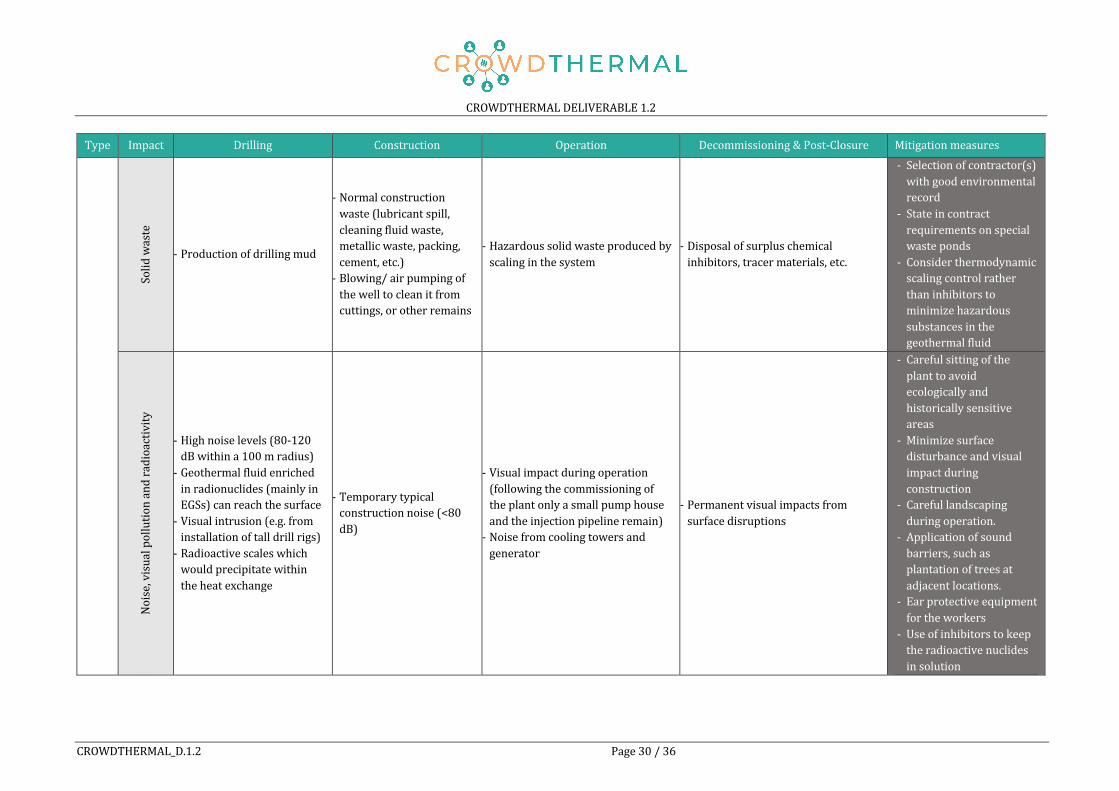
Type Impact Drilling Construction Operation Decommissioning&Post-Closure MitigationmeasuresSolidwaste
- Productionofdrillingmud
- Normalconstructionwaste(lubricantspill,cleaningfluidwaste,metallicwaste,packing,cement,etc.)- Blowing/airpumpingofthewelltocleanitfromcuttings,orotherremains
- Hazardoussolidwasteproducedbyscalinginthesystem
- Disposalofsurpluschemicalinhibitors,tracermaterials,etc.
- Selectionofcontractor(s)withgoodenvironmentalrecord
- Stateincontractrequirementsonspecialwasteponds
- Considerthermodynamicscalingcontrolratherthaninhibitorstominimizehazardoussubstancesinthegeothermalfluid
Noise,visualpollutionandradioactivity
- Highnoiselevels(80-120dBwithina100mradius)- Geothermalfluidenrichedinradionuclides(mainlyinEGSs)canreachthesurface- Visualintrusion(e.g.frominstallationoftalldrillrigs)- Radioactivescaleswhichwouldprecipitatewithintheheatexchange
- Temporarytypicalconstructionnoise(<80dB)
- Visualimpactduringoperation(followingthecommissioningoftheplantonlyasmallpumphouseandtheinjectionpipelineremain)- Noisefromcoolingtowersandgenerator
- Permanentvisualimpactsfromsurfacedisruptions
- Carefulsittingoftheplanttoavoidecologicallyandhistoricallysensitiveareas
- Minimizesurfacedisturbanceandvisualimpactduringconstruction
- Carefullandscapingduringoperation.
- Applicationofsoundbarriers,suchasplantationoftreesatadjacentlocations.
- Earprotectiveequipmentfortheworkers
- Useofinhibitorstokeeptheradioactivenuclidesinsolution

CROWDTHERMALDELIVERABLE1.2
CROWDTHERMAL_D.1.2 Page31/36
Type Impact Drilling Construction Operation Decommissioning&Post-Closure Mitigationmeasures
Shallowgeothermalsystem
s
Atmosphere
- Fugitiveemissions - Fugitiveemissions - Fugitiveemissions -
Water
- Connectionofdifferentaquiferlayersorconnectingaquiferstosurface- Drillingintoartesianwaterleadingtofloodingofbuildingsandinfrastructure- Swellableanhydriteformation
- Wateruseforconcreteproduction
- Riskfrompotentialleakageofantifreezeandothercompoundscouldcausegroundwatercontamination- Changesofsoiltemperatureleadingtoconcentrationofmicrobestogroundwaterresources
- Corrosionmaydamagethewellsandallowleakageofpollutantsintothegroundwater
- GroutingtheBoreholeHeatExchangers(BHE)orsealingtheannulus
- Legalconstraintsontheinstallationofgeothermalsystems(especiallyopenloop)inwaterprotectionareasfordrinkingwaters
Land
- LandsubsidencefromdrillingandgroutingofBHE.- Landuseduringthedrillingprocess- Upliftofthegroundsurfaceduetoswellingprocesses
- Landclearanceanduse- GHPsystemleadstolocaltemperaturechangesinthegroundaffectingtheecologicalbalance
-- Propersealingoftheboreholes,throughacementbasedbackfill
Solidwaste
- Welldrillingmudandcuttings
- Normalcontractor’sconstructionwaste
- Solidwaste,resultingfromoperationandmaintenanceoftheplant,aswellasurbanwastefromthepersonnel
- Wastematerialscanbesurpluschemicalinhibitors,tracermaterials,chemicalreagents
- Importanttoselectonlycontractor(s)thathavegoodenvironmentalrecord.Stateincontractrequirementsonspecialwasteponds

CROWDTHERMALDELIVERABLE1.2
CROWDTHERMAL_D.1.2 Page32/36
Type Impact Drilling Construction Operation Decommissioning&Post-Closure MitigationmeasuresNoise,visualpollutionandradioactivity
- Noisefromwelldrillingandvisualpollution
- Temporarystandardconstructionnoise - Minorvisualpollution -
- Applicationofhearingprotectionfortheworkers
- Noisebarrierstoavoiddisturbancesofresidentialareas
- Minimizesurfacedisturbanceandvisualimpactduringconstruction
- Carefullandscapingduringoperation
- Avoidingecologicallysensitiveareaswherepossible
*Environmentaleffectsprincipallyrefertohigh-enthalpydeepgeothermalsystems.

REFERENCESAgemar,Thorsten,JosefWeber,andRüdigerSchulz.2014.“DeepGeothermalEnergyProduction
inGermany.”Energies7(7):4397–4416.Allis,Rick.2000.“ReviewofSubsidenceatWairakeiField,NewZealand.”Geothermics29:455–78.Anderson,AustinandBehnazRezaie.2019.“GeothermalTechnology:TrendsandPotentialRole
inaSustainableFuture.”AppliedEnergy248:18–34.Arent,Doug,JacquelynPless,TrieuMai,RyanWiser,MaureenHand,SamBaldwin,GarvinHeath,
JordanMacknick,MorganBazilian,AdamSchlosser,andPaulDenholm.2014.“Implicationsof High Renewable Electricity Penetration in the U.S. for Water Use, Greenhouse GasEmissions,Land-Use,andMaterialsSupply.”AppliedEnergy123:368–77.
Ármannsson,Halldór,ThráinnFridriksson,andBjarniReyrKristjánsson.2005.“CO2EmissionsfromGeothermal Power Plants andNatural Geothermal Activity in Iceland.”Geothermics34(3):286–96.
Arnórsson, Stefán. 2004. “Environmental Impact of Geothermal EnergyUtilization.”GeologicalSociety,London,SpecialPublications236(1):297–336.
Bacci,E.,C.Gaggi,E.Lanzillotti,S.Ferrozzi,andL.Valli.2000.“GeothermalPowerPlantsatMt.Amiata (Tuscany–Italy): Mercury and Hydrogen Sulphide Deposition Revealed byVegetation.”Chemosphere40(8):907–11.
Barrick,KennethA.2007.“GeyserDeclineandExtinctioninNewZealand—EnergyDevelopmentImpacts and Implications for Environmental Management.” Environmental Management39(6):783–805.
Bayer,Peter, LadislausRybach,PhilippBlum, andRalfBrauchler.2013. “ReviewonLifeCycleEnvironmentalEffectsofGeothermalPowerGeneration.”RenewableandSustainableEnergyReviews26:446–63.
Bertani,R.andI.Thain.2002.“GeothermalPowerGeneratingPlantCO2EmissionSurvey.”IGANews49:1–3.
Bertani,Ruggero.2012.“GeothermalPowerGenerationintheWorld2005–2010UpdateReport.”Geothermics41:1–29.
Bisoniya,TrilokSingh.2015.“DesignofEarth–AirHeatExchangerSystem.”GeothermalEnergy3(1):18.
Bisoniya,TrilokSingh,AnilKumar,andPrashantBaredar.2014.“StudyonCalculationModelsofEarth-AirHeatExchangerSystems.”JournalofEnergy2014:1–15.
BLM.2008.BureauofLandManagement-FinalProgrammaticEnvironmentalImpactStatementforGeothermalLeasingintheWesternUnitedStates.WashingtonD.C.
Bloomfield,K.K., J.N.Moore, andR.M.Neilson.2003.GeothermalEnergyReducesGreenhouseGases.Vol.32.
Breede,Katrin,KhatiaDzebisashvili,XiaoleiLiu,andGioiaFalcone.2013.“ASystematicReviewofEnhanced (or Engineered) Geothermal Systems: Past, Present and Future.” GeothermalEnergy1(1):4.
Breede,K.,K.Dzebisashvili,andG.Falcone.2015.“OvercomingChallengesintheClassificationofDeep Geothermal Potential.” Geothermal Energy Science 3 (1): 19–39.https://doi.org/10.5194/gtes-3-19-2015.
Casasso and Sethi. 2019. “Groundwater-Related Issues of Ground Source Heat Pump (GSHP)Systems:Assessment,GoodPracticesandProposalsfromtheEuropeanExperience.”Water11(8):1573.
Chaldezos,I.P.andC.S.Karytsas.2017.“InnovativeHighEfficiencyClosedLoopGroundCoupledHeatExchanger(GCHE).”ProcediaEnvironmentalSciences38:102–6.
Clark, Corrie, Christopher Harto, John Sullivan, and Michael Wang. 2010. “Water Use in theDevelopmentandOperationofGeothermalPowerPlants.”ArgonneNatlLab.
Cook,David,BrynhildurDavíðsdóttir,andDaðiMárKristófersson.2017.“AnEcosystemServicesPerspective for Classifying andValuing theEnvironmental Impacts ofGeothermal PowerProjects.”EnergyforSustainableDevelopment40:126–38.
CRETA. 2018. Deliverable D.4.1.1 – Assessment and Mapping of Potential Interferences to the

CROWDTHERMALDELIVERABLE1.2
CROWDTHERMAL_D.1.2 Page34/36
InstallationofNSGESystemsintheAlpineRegions.DESTRESS. 2018. “Pohang, South Korea.” Retrieved June 10, 2020 (http://www.destress-
h2020.eu/en/demonstration-sites/pohang/).DiPippo,Ronald.2016.GeothermalPowerPlants.4th:Elsevier.Emmi,G.,A.Zarrella,M.DeCarli,M.Donà,andA.Galgaro.2017.“EnergyPerformanceandCost
AnalysisofSomeBoreholeHeatExchangerConfigurationswithDifferentHeat-CarrierFluidsinMildClimates.”Geothermics65:158–69.
Enex&GeysirGreenEnergy.2008.GeothermalUtilizationinEurope.Evans,KeithF.,AlbaZappone,ToniKraft,NicolasDeichmann,andFabioMoia.2012.“ASurveyof
the Induced Seismic Responses to Fluid Injection in Geothermal and CO2 Reservoirs inEurope.”Geothermics41:30–54.
Fleuchaus,PaulandPhilippBlum.2017.“DamageEventAnalysisofVerticalGroundSourceHeatPumpSystemsinGermany.”GeothermalEnergy5(1):10.
Flynn, Thomas, Fraser Goff, Ed Eeckhout, Sue Goff, Joe Ballinger, and Junji Suyama. 1991.“CatastrophicLandslideatZunilIGeothermalField,Guatemala.”Pp.425–33inTransactions-GeothermalResourcesCouncil.Vol.15.
Fthenakis, Vasilis and Hyung Chul Kim. 2010. “Life-Cycle Uses of Water in U.S. ElectricityGeneration.”RenewableandSustainableEnergyReviews14(7):2039–48.
GEA.2010.NewGeothermalTermsandDefinitions.AGuide toReportingResourceDevelopmentProgressandResultstotheGeothermalEnergyAssociation.WashingtonD.C.
Gil, AlejandroGarcía andMiguelMejíasMoreno. 2020. “Current Legal Frameworkon ShallowGeothermalEnergyUseinSpain.”JournalofSustainabilityResearch2(1):e200005.
Glover,RichardB.,TrevorM.Hunt,andCharlotteM.Severne.2000.“ImpactsofDevelopmentonaNaturalThermalFeatureandTheirMitigation—OhaakiPool,NewZealand.”Geothermics29(4–5):509–23.
Goldstein,B.,G.Hiriart,R.Bertani,C.Bromley,L.Gutierrez-negrin,ErnstHuenges,M.A.Muraoka,A.Ragnarsson, J.Tester,andV.Zui.2012.“GeothermalEnergy.”Pp.401–36inRenewableEnergySourcesandClimateChangeMitigation :SpecialReportoftheIntergovernmentalPanelon Climate Change, edited by O. Edenhofer, R. Pichs-Madruga, Y. Sokona, K. Seyboth, S.Kadner,T.Zwickel,P.Eickemeier,G.Hansen,S.Schlömer,C.vonStechow,andP.Matschoss.Cambridge.
GovernmentofCanada.2017.“Ground-SourceHeatPumps(Earth-EnergySystems).”RetrievedJuly 10, 2020 (https://www.nrcan.gc.ca/energy/publications/efficiency/heating-heat-pump/6833).
Haehnlein,Stefanie,PeterBayer,andPhilippBlum.2010.“InternationalLegalStatusoftheUseofShallowGeothermalEnergy.”RenewableandSustainableEnergyReviews14(9):2611–25.
Holm,Alison,DanJennejohn,andLeslieBlodgett.2012.GeothermalEnergyandGreenhouseGasEmissions.
Hunt,T.2000.“FiveLecturesonEnvironmentalEffectsofGeothermalEnergyUtilization.”P.109inReport1.Reykjavik/Iceland2001.
Klotzbücher, T., A. Kappler, K. L. Straub, and S. B. Haderlein. 2007. “Biodegradability andGroundwater Pollutant Potential of Organic Anti-Freeze Liquids Used in Borehole HeatExchangers.”Geothermics36(4):348–61.
Kraft,Toni,PaulMartinMai,StefanWiemer,NicholasDeichmann, JohannesRipperger,PhilippKästli, Corinne Bachmann, Donat Fäh, Jochen Wössner, and Domenico Giardini. 2009.“EnhancedGeothermalSystems:MitigatingRiskinUrbanAreas.”EOSTransactionAmericanGeophysicalUnion90(32):273–74.
Kristmannsdóttir,HrefnaandHalldórÁrmannsson.2003.“EnvironmentalAspectsofGeothermalEnergyUtilization.”Geothermics32:451–61.
Li,Tianyu,SogoShiozawa,andMarkW.McClure.2016.“ThermalBreakthroughCalculationstoOptimizeDesignofaMultiple-StageEnhancedGeothermalSystem.”Geothermics64:455–65.
Liu,WenandAndreaRamirez.2017.“StateoftheArtReviewoftheEnvironmentalAssessmentandRisksofUndergroundGeo-EnergyResourcesExploitation.”RenewableandSustainable

CROWDTHERMALDELIVERABLE1.2
CROWDTHERMAL_D.1.2 Page35/36
EnergyReviews76:628–44.Lund,JohnW.andTonyaL.Boyd.2016.“DirectUtilizationofGeothermalEnergy2015Worldwide
Review.”Geothermics60:66–93.Macknick,Jordan,RobinNewmark,GarvinHeath,andK.C.Hallett.2011.AReviewofOperational
WaterConsumptionandWithdrawalFactorsforElectricityGeneratingTechnologies.Majer,ErnestL.2006.InducedSeismicityAssociatedwithEnhancedGeothermalSystem.Majer,ErnestL.,RoyBaria,MitchStark,StephenOates, JulianBommer,BillSmith,andHiroshi
Asanuma. 2007. “Induced Seismicity Associated with Enhanced Geothermal Systems.”Geothermics36(3):185–222.
Majer, Ernie, JamesNelson,AnnTait, and IvanWong. 2012. “Protocol forAddressing InducedSeismicityAssociatedwithEnhancedGeothermalSystems.”
Mannvithf.2013.EnvironmentalStudyonGeothermalPowerGEOELECProject-WP4D4.2.Manzella,AdeleandEtAl.2019.GEOENVIProject,D.2.2:ReportonMitigationMeasures:Adopted
SolutionsandRecommendationstoOvercomeEnvironmentalConcerns.Manzella,Adele,RobertoBonciani,AgnesAllansdottir, SerenaBotteghi,AssuntaDonato, Silvia
Giamberini, Alessandro Lenzi, Marco Paci, Anna Pellizzone, and Davide Scrocca. 2018.“EnvironmentalandSocialAspectsofGeothermalEnergyinItaly.”Geothermics72:232–48.
Martín-Gamboa, Mario, Diego Iribarren, and Javier Dufour. 2015. “On the EnvironmentalSuitabilityofHigh-andLow-EnthalpyGeothermalSystems.”Geothermics53:27–37.
Masum,Mohammed. 2015. “Low-TemperatureGeothermal Systems in SedimentaryBasin andTheirProspectinBangladesh.”inWorldGeothermalCongress.Melbourne.
McCay,AlistairT.,MichaelE.J.Feliks,andJenniferJ.Roberts.2019.“LifeCycleAssessmentoftheCarbonIntensityofDeepGeothermalHeatSystems:ACaseStudyfromScotland.”ScienceofTheTotalEnvironment685:208–19.
McComas,KatherineA.,HangLu,KatieM.Keranen,MariaA.Furtney,andHwansuckSong.2016.“Public Perceptions and Acceptance of Induced Earthquakes Related to EnergyDevelopment.”EnergyPolicy99:27–32.
Ravier,Guillaume,ClémentBaujard,EléonoreDalmais,VincentMaurer,andNicolasCuenot.2016.“TowardsaComprehensiveEnvironmentalMonitoringofaGeothermalPowerPlantintheRhineGraben.”inEuropeanGeothermalCongress2016.Strasbourg.
Reith,Sören,ThomasKölbel,PascalSchlagermann,AnnaPellizzone,andAgnesAllansdottir.2013.“PublicAcceptanceofGeothermalElectricityProduction.”
Rissmann,Clinton,BruceChristenson,CynthiaWerner,MatthewLeybourne,JimCole,andDarrenGravley.2012.“SurfaceHeatFlowandCO2EmissionswithintheOhaakiHydrothermalField,TaupoVolcanicZone,NewZealand.”AppliedGeochemistry27(1):223–39.
Rosea, Peter E., Walter R. Benoitb, and Phaedra M. Kilbourn. 2001. “The Application of thePolyaromaticSulfonatesasTracersinGeothermalReservoirs.”Geothermics30:617–640.
Sanner,Burkhard.2019.“SummaryofEGC2019CountryUpdateReportsonGeothermalEnergyinEurope.”inEuropeanGeothermalCongress2019.DenHaag.
Sanner,Burkhard,OlofAndersson,WalterJ.Eugster,GöranHellström,IñigoArrizabalaga,DavidBanks, Radu Hanganu-Cucu, Javier F. Urchueguía, Paul Sikora, David Norbury, and RaduPolizu.2011.GEOTRAINETTrainingManualforDesignersofShallowGeothermalSystems-Geo-Education for a Sustainable Geothermal Heating and Cooling Market. Project:IEE/07/581/S12.499061.Brussels.
Sass,IngoandUlrichBurbaum.2010.“DamagetotheHistoricTownofStaufen(Germany)CausedbyGeothermalDrillingsthroughAnhydrite-BearingFormations.”ActaCarsologica39(2).
Serdjuk, Martina, P Dumas, L Angelino, and L Tryggvadóttir. 2013. “Geothermal InvestmentGuide.”http://www.geoelec.eu/wp-content/uploads/2011/09/D3.4.pdf.
Tassi, F., O. Vaselli, F. Cuccoli, A. Buccianti, B. Nisi, E. Lognoli, and G. Montegrossi. 2009. “AGeochemical Multi-Methodological Approach in Hazard Assessment of CO2-Rich GasEmissionsatMt.AmiataVolcano(Tuscany,CentralItaly).”Water,Air,&SoilPollution:Focus9(1):117–27.
Thráinn,Fridriksson,AlmudenaMateos,PierreAudinet,andYaseminOrucu.2016.Greenhouse

CROWDTHERMALDELIVERABLE1.2
CROWDTHERMAL_D.1.2 Page36/36
GasesfromGeothermalPowerProduction.WashingtonD.C.Tomarov,G.V.,andA.A.Shipkov.2017.“ModernGeothermalPower:BinaryCycleGeothermal
Power Plants.” Thermal Engineering 64 (4): 243–50.https://doi.org/10.1134/S0040601517040097.
Tomasini-Montenegro,C.,E.Santoyo-Castelazo,H.Gujba,R.J.Romero,andE.Santoyo.2017.“LifeCycle Assessment of Geothermal Power Generation Technologies: An Updated Review.”AppliedThermalEngineering114:1119–36.
Trutnevyte, Evelina and Stefan Wiemer. 2017. “Tailor-Made Risk Governance for InducedSeismicity of Geothermal Energy Projects: An Application to Switzerland.” Geothermics65:295–312.
USDepartmentofEnergy.2004.GeothermalTechnologiesProgram.TheEnvironmental,Economic,andEmploymentBenefitsofGeothermalEnergy.Washington.
Vetter,O.J.1983.“SolidWasteProblemsinGeothermalOperations.”inSPECaliforniaRegionalMeeting.SocietyofPetroleumEngineers.
Zhu, Ke, Liang Fang, Nairen Diao, and Zhaohong Fang. 2017. “Potential UndergroundEnvironmentalRiskCausedbyGSHPSystems.”ProcediaEngineering205:1477–83.