syntheyesum
TRANSCRIPT

SynthEyes™ 2007.5.1010 User Manual ©2003-2007 Andersson Technologies LLC
Welcome to the SynthEyes™ camera-tracking system (also known as
match-moving). With SynthEyes, you can process your film or video shot to determine the motion and field of view of the camera taking the shot, or track an object moving within it. You can combine feature locations to produce an object mesh. After reviewing the match-moved shot, inserting some sample 3-D objects and viewing the RAM playback, you can output the camera and/or object motions to any of a large number of popular 3-D animation programs. Once in your 3-D animation program, you can add 3-D effects to the live-action shot, ranging from invisible alterations, such as virtual set extensions, to virtual product placements, to over-the-top creature insertions. With the right setup, you can capture the motion of an actor’s body or face.
SynthEyes can also help you stabilize your shots, taking full advantage of its two and three-dimensional tracking capabilities to help you generate rock-solid moving-camera shots. The comprehensive stabilization feature set gives you full directorial control over stabilization.
If you work with film images, especially for TV, the stabilization system can also help you avoid some common mistakes in film workflows that compromise 3-D tracking, rendering, and effects work.
Unless you are using the demo version, you will need to follow the registration and authorization procedure described towards the end of this document.
To help provide the best user experience, SynthEyes has a Customer Care center with automatic updates, messages from the factory, feature suggestions, forum, and more. Be sure to take advantage of these capabilities.
If you are reading this document in HTML format, you can access it in PDF form from within SynthEyes using the Help/Help PDF item. The PDF version has pre-built bookmarks (contents) that make it easy to read. If you are using the demo version, the PDF version is a separate download.
Contents Quick Start: Automatic TrackingQuick Start: Supervised TrackingQuick Start: StabilizationShooting Requirements for 3-D EffectsBasic OperationOpening the ShotAutomatic TrackingSupervised TrackingChecking The TrackersSetting Up a Coordinate SystemLenses and DistortionRunning the 3-D Solver3-D ReviewZero-Weighted Trackers Perspective WindowExporting to Your Animation PackageTroubleshootingCombining Automatic and Supervised TrackingStabilizationRotoscoping and Alpha-Channel MattesObject TrackingJoint Camera and Object TrackingMulti-Shot TrackingFinding Light PositionsBuilding Meshes from Tracker PositionsCurve Tracking and Analysis in 3-DMotion Capture and Face TrackingMerging Files and TracksBatch File Processing
Reference Material: System Requirements
Installation and RegistrationCustomer Care Features and Automatic UpdateViewport Layout ManagerWindow Feature Reference Perspective Window ReferenceControl Panel ReferenceMenu ReferencePreferences and Scene Settings ReferenceKeyboard ReferenceSupport

Quick Start: Automatic Tracking To get started quickly with SynthEyes, match-move the demo shot
FlyoverJPEG, downloaded from http://www.ssontech.com/download.htm. Unpack the ZIP file into a folder containing the image sequence.
An overview of the tracking process looks like this:
• Open the shot and configure SynthEyes to match the source • Create 2-D trackers that follow individual features in the image, either
automatically or under user supervision. • Analyze (solve) the 2-D tracks to create 3-D camera and tracker data. • Set up constraints to align the solved scene in a way useful for adding
effects. This step can be done before solving as well. • Export to your animation package.
Start SynthEyes from the shortcut on your desktop, and select File/New or File/Import/Shot. Select the first frame, FLYOVER0000.JPG, in the shot.
The shot settings panel will appear. Screenshots in this manual are from a PC with the light-colored user interface option so that they print better; the OS X and/or dark-colored interfaces are slightly different in appearance but not function.
You can reset the frame rate from the 24 fps default for sequences to the
NTSC rate by hitting the NTSC button, though this is not critical. The aspect ratio, 1.333 is correct for this shot. If your machine has enough RAM, the queue length

should already be 150 frames, enough to buffer the entire shot in RAM for maximum speed.
On the toolbar, verify that the summary panel button is selected.
On the summary panel, click Full Automatic. A series of message boxes will pop up showing the job being processed.
Wait for it to finish. This is where your computer’s speed pays off. On a 3.0 GHz Pentium 4, the shot takes about 20 seconds to process.
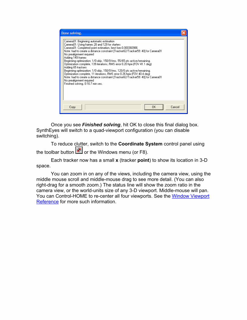
Once you see Finished solving, hit OK to close this final dialog box. SynthEyes will switch to a quad-viewport configuration (you can disable switching).
To reduce clutter, switch to the Coordinate System control panel using
the toolbar button or the Windows menu (or F8). Each tracker now has a small x (tracker point) to show its location in 3-D
space. You can zoom in on any of the views, including the camera view, using the
middle mouse scroll and middle-mouse drag to see more detail. (You can also right-drag for a smooth zoom.) The status line will show the zoom ratio in the camera view, or the world-units size of any 3-D viewport. Middle-mouse will pan. You can Control-HOME to re-center all four viewports. See the Window Viewport Reference for more such information.
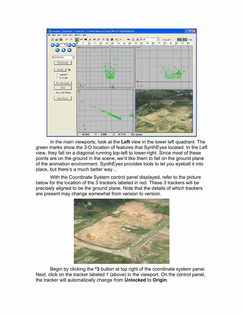
In the main viewports, look at the Left view in the lower left quadrant. The
green marks show the 3-D location of features that SynthEyes located. In the Left view, they fall on a diagonal running top-left to lower-right. Since most of these points are on the ground in the scene, we’d like them to fall on the ground plane of the animation environment. SynthEyes provides tools to let you eyeball it into place, but there’s a much better way…
With the Coordinate System control panel displayed, refer to the picture below for the location of the 3 trackers labeled in red. These 3 trackers will be precisely aligned to be the ground plane. Note that the details of which trackers are present may change somewhat from version to version.
Begin by clicking the *3 button at top right of the coordinate system panel.
Next, click on the tracker labeled 1 (above) in the viewport. On the control panel, the tracker will automatically change from Unlocked to Origin.

In this example, we will use trackers (1 and 2) aligned front to back. The coordinate system mini-wizard (*3 button) handles points aligned left to right or front to back. By default, it is at LR, so click the *3 button, which currently reads LR, to change it to FB.
Click the tracker labeled 2, changing it to Lock Point. The Y field above it will change to 20. The full-screen capture (above) showed SynthEyes right after completing this step.
Select the tracker labeled 3, slightly right of center. It will change from Unlocked to On XY Plane (ie the ground plane).
Why are we doing all this? The choice of trackers to use, the overall size (determined by the 20 value above), and the choice of axes is arbitrary, up to you to make your subsequent effects easier. See Setting Up the Coordinate System for more details on why and how to set up a coordinate system. Note that SynthEyes’ scene settings and preferences allow you to change how the axes are oriented to match other programs such as Maya or Lightwave: ie a Z-up or Y-up mode. This manual’s examples are in Z-Up mode unless otherwise noted; the corresponding choices for one of the Y-Up modes should be fairly evident.
After you click the third tracker you will be prompted (“Apply coordinate system?”) to determine whether the scene should be re-solved to apply your new settings. Select Yes. Hit Go! and SynthEyes will recalculate the tracker and camera positions in a flash. To do this SynthEyes changed the solving mode (on
the Solver control panel ) from Automatic to Refine, so that it will update the match-move, rather than recalculating from scratch.
Afterwards, the 3 trackers will be flat on the ground plane (XY plane) and the camera path adjusted to match, as shown:

You could have selected any three points to define the coordinate system this way, as long as they aren’t in a straight line or all bunched together. The points you select should be based on how you want the scene to line up in your animation package.
Switch to the 3-D control panel . Select the magic wand tool on the panel. Change from creating a Box to Pyramid. Zoom in the Top viewport window so the tracker points are spread out.
In the Top viewport, drag out the base of a rectangular pyramid. Then click again and drag to set its height. Use the move, rotate, and scale tools to make the box into a small pyramid located in the vacant field. Click on the color swatch under the wand, and select a sandy pyramid color. Click somewhere empty in the viewport to unselect the pyramid (bright red causes lag in LCDs).
Hit Play. On the View menu, turn off Show Trackers and Show 3-D Points, and switch to the camera viewport.
Note that there will appear to be some jitter because drawing is not anti-
aliased: it is done by Windows. It won’t be present when you render in your 3-D application. SynthEyes is not intended to be a rendering or modeling system; it operates in conjunction with a separate 3-D animation application. (You can create anti-aliased preview movies from the Perspective window.)
Hit Stop. If you see a delayed reaction to the stop button, Edit/Preferences and turn on the Enhance Tablet Responsiveness checkbox. Rewind to the beginning of the shot (say with shift -A).
By far, the most common cause of “sliding” of an inserted object is that the object has not been placed at the right altitude over the imagery. You should

compare the location of your insert to that of other nearby trackers, adding a tracker at key locations if necessary. You will also think you have sliding if you place a flat object onto a surface that is not truly flat.
To make a preview movie, switch to the Perspective window. Right-click and select Lock to Current Cam. Right-click again and select Preview Movie.
Click on … at upper right and select a file for the output movie in
QuickTime format, typically in a temporary scratch location. (If you don’t have QuickTime installed, use one of the sequenced file types and SynthEyes or a separate video playback program.) Click on Compression Settings, and select Sorensen Video 3 at High Quality, 29.97 frames per second, leave the Key Frames checkbox on, and turn off the Limit data rate checkbox. Click OK to close the compression settings. Back on the Preview Movie Settings, turn off Show Grid, and hit Start. The preview movie will be produced and played back in the Quicktime Player.
You can export to your animation package at this time, from the File/Export menu item. SynthEyes will prompt for the location and file name; by default a file with the same name as the currently-open file (flyover in this case), but with an appropriate file extension, such as .ma for a Maya ASCII scene file.
This completes this initial example, which is the quickest, though not necessarily always the best, way to go. You’ll notice that SynthEyes presents many additional views, controls, and displays for detecting and removing tracking glitches, navigating in 3-D, handling temporarily obscured trackers, moving objects and multiple shots, etc.
In particular, after auto-tracking and before exporting, you should always check up on the trackers, especially using the tracker graph view, to correct any glitches in tracking (which can result in little glitches in the camera path), and to

eliminate any trackers that are not stable. For example, in the example flyover, the truck that is moving behind the trees might be tracked, and it should be deleted and the solution refined (quickly recomputed).
The final scene is available from the web site as flyover_auto.sni.
Quick Start: Supervised Tracking Sometimes you will need to “hand track” shots, add additional supervised
trackers to an automatic track, or add supervised trackers to help the automated system with very jumpy shots. Although supervised tracking takes a bit more knowledge, it can often be done relatively quickly, and produce results on shots the automated method can not handle.
To demonstrate, manually match-move the demo shot flyover. Start SynthEyes and select File/New or File/Import/Shot. Open the flyover shot.
The shot settings panel will appear. If your computer’s memory permits, use a queue length equal to the entire shot length, as you will scrub back and forth through the entire shot repeatedly.
The first major step is to create trackers, which will follow selected features in the shot. We will track in the forward direction, from the beginning of the shot to the end, so rewind to the beginning of the shot. On shots where features approach from the distance, it is often more convenient to track backwards.
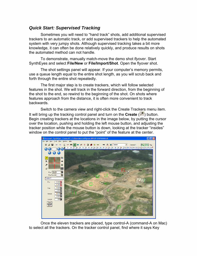
Switch to the camera view and right-click the Create Trackers menu item. It will bring up the tracking control panel and turn on the Create ( ) button. Begin creating trackers at the locations in the image below, by putting the cursor over the location, pushing and holding the left mouse button, and adjusting the tracker position while the mouse button is down, looking at the tracker “insides” window on the control panel to put the “point” of the feature at the center.
Once the eleven trackers are placed, type control-A (command-A on Mac)
to select all the trackers. On the tracker control panel, find where it says Key
[Now], followed by a spinner containing 0. The [Now] is a button. Raise the spinner from zero to 20. This says you wish to automatically re-key the tracker every 20 frames to accommodate changes in the pattern.
Hit the Play button, and SynthEyes will track through the entire shot. The timebar will change from a dark-pink background to white as it does, indicating that the frames are in RAM cache.
On this example, the trackers should stay on their features throughout the entire shot without further intervention. You will notice that one has gone off-screen and been shut down automatically. (Advanced feature hint: when the image has black edges, you can adjust the Region-of-interest on the image preprocessing panel to save storage and ensure that the trackers turn off when they reach the out-of-bounds portion.) If necessary, you can reposition a tracker on any frame, setting a key and teaching the tracker to follow the image from that location subsequently.
After tracking, with all the trackers still selected (or hit Control/command-A), click the Lock ( ) button to lock them, so they will not retrack as you play around (or get messed up…).
Now you will align the coordinate system. This is the same as for automatic tracking, except performed before any solving. See Setting Up the Coordinate System for more details on why and how to set up a coordinate
system. Switch to the Coordinate System control panel using the toolbar.
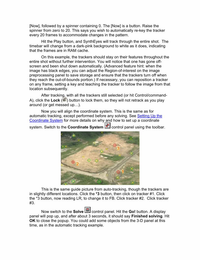
This is the same guide picture from auto-tracking, though the trackers are
in slightly different locations. Click the *3 button, then click on tracker #1. Click the *3 button, now reading LR, to change it to FB. Click tracker #2. Click tracker #3.
Now switch to the Solve control panel. Hit the Go! button. A display panel will pop up, and after about 3 seconds, it should say Finished solving. Hit OK to close the popup. You could add some objects from the 3-D panel at this time, as in the automatic tracking example.

You can add some additional trackers now to increase accuracy. Use (or shift-F) to go to the end of the shot, and change to backward tracking by clicking the on the tracker control panel, not main toolbar. On the Tracker control panel, turn on the Create ( ) button.
Create additional trackers spread through the scene, for example only on white spots. Switch their tracker type from a match tracker to a white-spot tracker , using the type selection button on the tracker control panel. (Note that the Key-every spinner does not affect spot-type trackers.)
Hit Play to track them out. The tracker on the rock pile gets off-track in the
middle—you can either correct it by dragging and re-tracking, or by keeping it as a match-type tracker.
Switch to the Solver control panel, change the mode box from Automatic to Refine, and hit Go! again.
Go to the 3-D Panel, and insert an Earthling or two to menace this busy setting. The tracker on the pad was used to adjust the height of the statue to prevent sliding. You can use pan-to-follow (5 key) to zoom in on the tracker (and nearby feet) to monitor their positioning as you scrub. The final scene is available from the web site as flyover_sup.sni.

Quick Start: Stabilization Adding 3-D effects generally requires a moving camera, but making a
camera move smoothly can be hard, and a jiggly shot often cries out “Amateur!” SynthEyes can help you stabilize your shots for a more professional look, though like any tool it is not a magic wand: a more stable original shot is always better. Stabilization will sacrifice some image quality. We’ll discuss more costs and benefits of SynthEyes stabilization in the later full section.
We’ll begin by stabilizing the shot grnfield, available from the web site. We will do this shot one particular way for illustration, though many other options are possible. Note that this shot orbits a feature, which will be kept in place. SynthEyes also can stabilize traveling shots, such as a forward-looking view from a moving car, where there is no single point that stays in view.
Open the shot using the standard 4:3 defaults. You can play through it and see the bounciness: it was shot out a helicopter door with no mechanical stabilizing equipment.
Click the Full Automatic button on the summary panel to track and solve the shot. If we wanted, we could track without solving, and stick with 2-D tracks, but we’ll use the more stable and useful 3-D results here.
Select the Shot/Image Preparation menu item (or hit the P key). In the image prep viewport, drag a lasso around the half-dozen trackers in
the field near the parking lot at left. We could stabilize using all the trackers, but for illustration we’ll stabilize this particular group, which would be typical if we were adding a building into the field.
On the stabilization tab, change the Translation stabilization-axis drop-down to Peg, and the Rotation drop-down to Filter. Reduce the Cut Frequency spinner to 0.5 Hz. This will attenuate rotation instability, without eliminating it. You should have something like this:
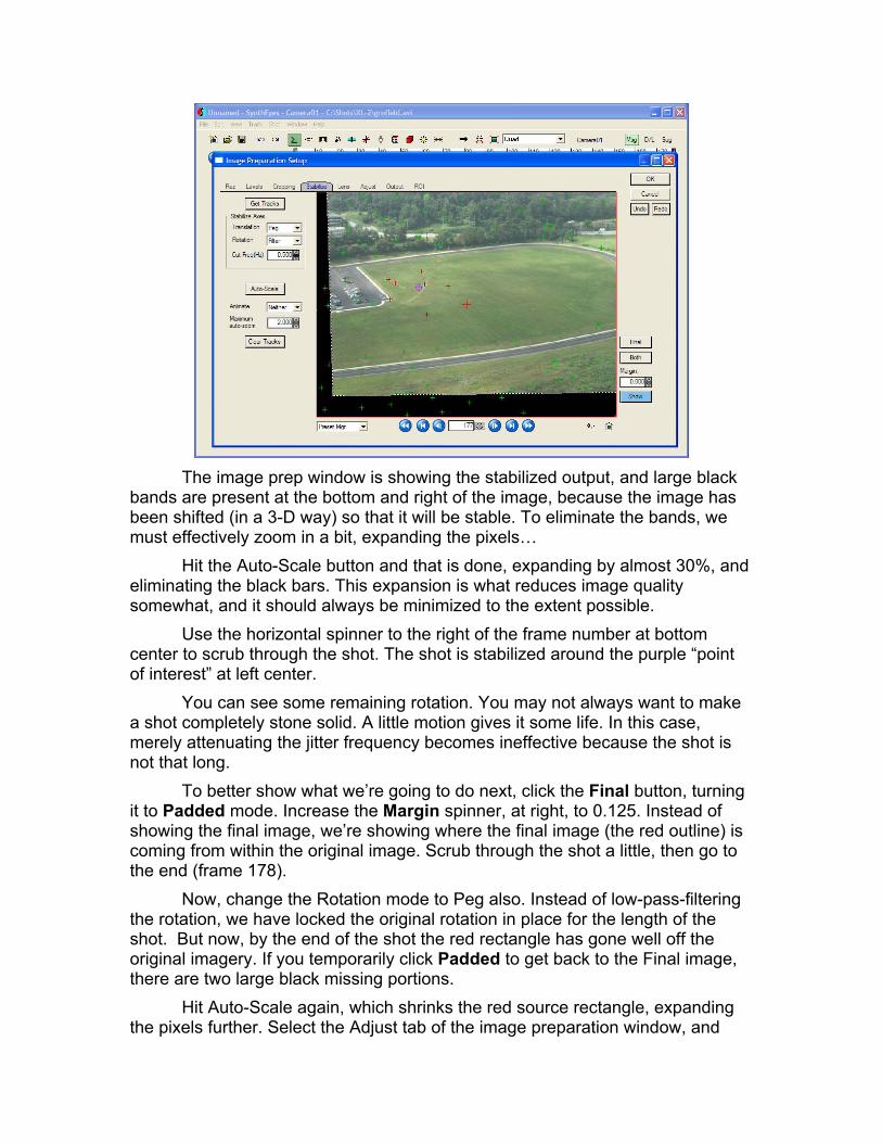
The image prep window is showing the stabilized output, and large black
bands are present at the bottom and right of the image, because the image has been shifted (in a 3-D way) so that it will be stable. To eliminate the bands, we must effectively zoom in a bit, expanding the pixels…
Hit the Auto-Scale button and that is done, expanding by almost 30%, and eliminating the black bars. This expansion is what reduces image quality somewhat, and it should always be minimized to the extent possible.
Use the horizontal spinner to the right of the frame number at bottom center to scrub through the shot. The shot is stabilized around the purple “point of interest” at left center.
You can see some remaining rotation. You may not always want to make a shot completely stone solid. A little motion gives it some life. In this case, merely attenuating the jitter frequency becomes ineffective because the shot is not that long.
To better show what we’re going to do next, click the Final button, turning it to Padded mode. Increase the Margin spinner, at right, to 0.125. Instead of showing the final image, we’re showing where the final image (the red outline) is coming from within the original image. Scrub through the shot a little, then go to the end (frame 178).
Now, change the Rotation mode to Peg also. Instead of low-pass-filtering the rotation, we have locked the original rotation in place for the length of the shot. But now, by the end of the shot the red rectangle has gone well off the original imagery. If you temporarily click Padded to get back to the Final image, there are two large black missing portions.
Hit Auto-Scale again, which shrinks the red source rectangle, expanding the pixels further. Select the Adjust tab of the image preparation window, and
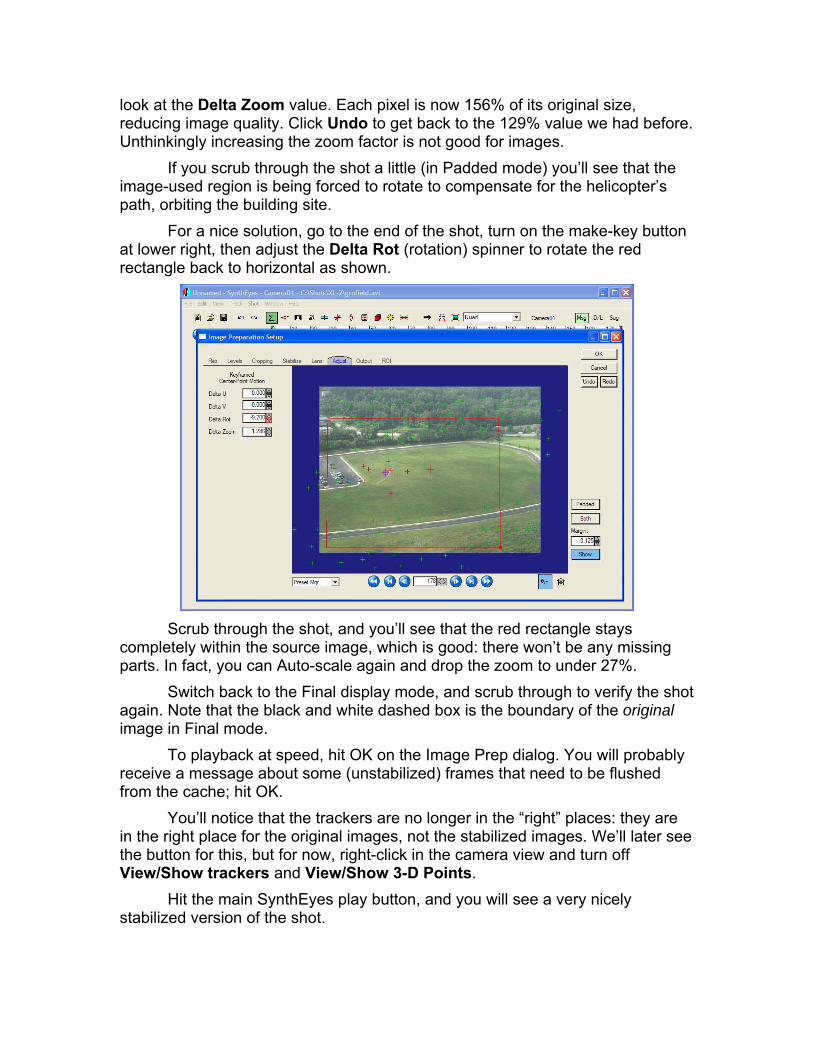
look at the Delta Zoom value. Each pixel is now 156% of its original size, reducing image quality. Click Undo to get back to the 129% value we had before. Unthinkingly increasing the zoom factor is not good for images.
If you scrub through the shot a little (in Padded mode) you’ll see that the image-used region is being forced to rotate to compensate for the helicopter’s path, orbiting the building site.
For a nice solution, go to the end of the shot, turn on the make-key button at lower right, then adjust the Delta Rot (rotation) spinner to rotate the red rectangle back to horizontal as shown.
Scrub through the shot, and you’ll see that the red rectangle stays
completely within the source image, which is good: there won’t be any missing parts. In fact, you can Auto-scale again and drop the zoom to under 27%.
Switch back to the Final display mode, and scrub through to verify the shot again. Note that the black and white dashed box is the boundary of the original image in Final mode.
To playback at speed, hit OK on the Image Prep dialog. You will probably receive a message about some (unstabilized) frames that need to be flushed from the cache; hit OK.
You’ll notice that the trackers are no longer in the “right” places: they are in the right place for the original images, not the stabilized images. We’ll later see the button for this, but for now, right-click in the camera view and turn off View/Show trackers and View/Show 3-D Points.
Hit the main SynthEyes play button, and you will see a very nicely stabilized version of the shot.
By adding the hand-animated “directorial” component of the stabilization, we were able to achieve a very nice result, without requiring an excessive amount of zoom. [By intentionally moving the point of interest, the required zoom can be reduced under 15%.]
If you look carefully at the shot, you will notice some occasional strangeness where things seem to go out of focus temporarily. This is the motion blur due to the camera’s motion during shooting.
Important: To minimize motion blur when shooting footage that will be stabilized, keep the camera’s shutter time as small as possible (a small “shutter angle” for film cameras).
Doubtless you would now like to save the sequence out for later compositing with final effects (or maybe a stabilized shot is all you needed). Hit P to bring the image prep dialog back up, and select the Output tab. Click the Save Sequence button.
Click the … button to select the output file type and name. Note that for image sequences, you should include the number of zeroes and starting frame number that you want in the first image sequence file name: seq001 or seq0000 for example. After setting any compression options, hit Start, and the sequence will be saved.
There are a number of things which have happened behinds the scene during this quick start, where SynthEyes has taken advantage of the 3-D solve to produce better results than traditional stabilizing software.
And SynthEyes has plenty of additional controls affording you directorial control, and the ability to combine some workflow operations that normally would be separate, improving final image quality in the process. These are described later in the Stabilization section of the manual.
Shooting Requirements for 3-D Effects You’ve seen how to track a simple demo shot. How about your own
shots? Not every shot is suitable for match-moving. If you can not look at the shot and have a rough idea of where the camera went and where the objects are, SynthEyes won’t be able to either. It’s helpful to understand what is needed to get a good match-move, to know what can be done and what can’t, and sometimes to help a project’s director or camera-person plan the shots for effects insertion.
This list suggests what is necessary:
• The camera must physically change location: a simple pan, tilt, or zoom is not enough for 3-D scene reconstruction.
• Depth of scene: everything can not be the same distance, or very far, from the camera.
• Distinct trackable features in the shot (reflected highlights from lights do not count and must be avoided).
• The trackable features should not all be in the same plane, for example, they should not all be on a flat floor or green-screen on the back wall. If the camera did not move, then either
• You must need only the motion of a single object that occupies much of the screen while moving nontrivially in 3-D (maybe a few objects at film resolution),
• Or, you must make do with a “2½ -D” match-move, which will track the camera’s panning, tilting, and zooming, but can not report the distance to any point,
• Or, you must shoot some separate still or video imagery where the camera does move, which can be used to determine the 3-D location of features tracked in the primary shot. For this second group of cases, if the camera spins around on a tripod, it
is IMPOSSIBLE, even in theory, to determine how far away anything is. This is not a bug. SynthEyes’ tripod tracking mode will help you insert 3-D objects in such shots anyway. The axis alignment system will help you place 3-D objects in the scene correctly. It can also solve pure lock-off shots.
If the camera was on a tripod, but shoots a single moving object, such as bus driving by, you may be able to recover the camera pan/tilt plus the 3-D motion of the bus relative the camera. This would let you insert a beast clawing into the top of the bus, for example.
For visual examples, see the Tutorials section of our web site.

Basic Operation Before describing the match-moving process in more detail, here is an
overview of the elements of the user interface, beginning with an annotated image. Details on each element can be found in the reference sections.
Color Scheme SynthEyes offers two default color schemes, a light version (shown) and a
dark version. The light version generally matches the operating system defaults (and so is somewhat different on a PC and Mac), intended for a brighter office-style environment. The darker user-interface scheme matches programs such as Combustion, Fusion, Shake, etc, which are designed to be used in a darker studio environment.
To switch schemes, select the Edit/Reset Preferences menu item and you will be given a choice.
You can change virtually all of the colors in the user interface individually, if you like. For example, you can change the default tracker color from green to blue, if you are handling green-screen shots. See Keeping Track of the Trackers for more information.
Tool Bar The tool bar runs across the top of the application, including normal
Windows icons, buttons to switch among the control panels, and several viewport
controls. SynthEyes includes full undo and redo support. Three buttons at right control Customer Care Center functions such as messages and upgrades.
Control Panels At any time, one of the control panels is displayed in the control panel
area, as selected by the toolbar buttons or some menu items. The control panel can be floated by the Window/Floating Panel menu item. You can use a control panel with any viewport.
Floating Camera View The camera view can be floated with Window/Floating Camera. For
example, you can move it to a second monitor. The camera view will be empty in all viewport layouts that would normally contain the camera view—using Quad Perspective instead can be very handy.
Mac OS X Tip: If you float both the camera view and control panel, with the control panel on top of the camera view, then click on the title bar of the camera view, the control panel will be moved by OS X behind the camera view, which will cause it to disappear from view. Un-float and re-float the command view. This should rarely be necessary.
Play Bar The play bar appears at the top of most control panel selections, and
features the usual play/stop, frame forward, etc controls as well as the frame number display. Frames are numbered from 0 unless you adjust the preferences.
Viewports The main display area can show a single viewport, such as a Top or
Camera View, or several independent viewports simultaneously as part of a layout, such as Quad.
Coordinate Systems SynthEyes can operate in any of several different coordinate system
alignments, such as Z up, Y up, or Y up left-handed (Lightwave). The coordinate axis setting is controlled from Edit/Scene Settings; the default setting is controlled from the Edit Preferences.
The viewports should the directions of each coordinate axis, X in red, Y in green, Z in blue. One axis is out of the plane of the screen, and is labeled as t(towards) or a(away). For example, in the Top view in Z-up mode, the Z axis is labeled Zt.
SynthEyes automatically adjusts the scene and user interface when you change the coordinate system setting. If a point is at X/Y/Z = 0,0,10 in Z-up mode, then if you change to Y up mode, the point will be at 0,10,0. Effectively, SynthEyes preserves the view from each direction: Top, Front, Left, etc, so that

the view from each direction never changes as you change the coordinate system setting. The axis will shift, and the coordinates of the points and cameras.
Consequently, you can change the scene coordinate axis setting whenever you like, and some exporters do it temporarily to match the target application.
Layouts A layout consists of one or more viewports, shown simultaneously. Select
the layout with the drop-down list on the toolbar. Modify layouts with the layout manager from the Window menu. Many viewport types can appear only once in a particular layout: you can’t have two tracker graph viewports in one layout.
Active Camera/Object versus Selection At any point in time, one camera or moving object is considered active.
The list of cameras and objects may be found on the Shot menu; the active one is checked and listed in the button to the the right of the viewport selection on the toolbar.
The active object (meaning a moving object or camera) will have its shot shown in the Camera view, and its trackers visible and editable. The active object, or all objects on its shot, will be exported, depending on the exporter.
Trackers, objects, mesh objects, cameras, and lights can all be selected, for example by clicking on them or by name through the drop-down on the 3-D panel. While any number of trackers on a single object can be selected at a time, only a single other object can be selected at a given time.
In the perspective window, a single mesh object can be selected as the “Edit Mesh,” where its facets and vertices are exposed and subject to editing.
Note that a moving object can be active, but not selected, and vice versa. Similarly, a mesh object can be selected but not the edit mesh, and vice versa.
Spinners
Spinners are the up/down arrow things next to the numeric edit fields. You can drag upwards and downwards from within the spinner to rapidly adjust the value, or click the up or down arrow to change a little at a time. Some spinners show keyed frames with a red outline. You can remove a key or reset a spinner to a default or initial value by right-clicking it.
Tooltips Tooltips are helpful little boxes of text that pop up when you put the mouse
over an item for a little while. There are tooltips for the controls, to help explain their function, and tooltips in the viewports to identify tracker and object names.
The tooltip of a tracker has a background color that shows whether it is an automatically-generated tracker (lead gray), or supervised tracker (gold).

Status Line Some mouse operations display current position information on the status
line at the bottom of the overall SynthEyes window, depending on what window the mouse is in, and whether it is dragging. For example, zooming in the camera view shows a relative zoom percentage, while zooming in a 3-D viewport shows the viewports width and height in 3-D units.
Keyboard Accelerators SynthEyes offers keyboard accelerators, as listed in the reference section.
You can change the keyboard accelerators from the keyboard manager, initiated with Edit/Edit Keyboard Map. Note that the tracker-related commands will work only from within the camera view, so that you do not inadvertently corrupt a tracker.
On a PC, you can also use Windows’s ALT-whatever acceleration to access the menu bar, such as ALT-F-X to exit.
Click-on/Click-off Mode Tracking can involve substantial sustained effort by your hands and wrists,
so proper ergonomics are important to your workstation setup, and you should take regular breaks.
As another potential aid, SynthEyes offers click-on/click-off mode, which replaces the usual dragging of items around with a click-on/move/click-off approach. In this mode, you do not have to hold the mouse buttons down so much, especially as you move, so there should be less strain (though we can not offer a medical opinion on this, use at your own risk and discretion).
You can set the click-on/click-off mode as a preference, and can switch it on and off whenever convenient from the Window menu.
Click-on/click-off mode affects only the camera view, mini-tracker view, 3-D viewports, perspective window, and spinners, and affects only the left and middle mouse buttons, never the right. This captures the common needs, without requiring an excess of clicking in other scenarios.

Opening the Shot To begin tracking a shot, select File/New or File/Import/Shot if you just
started SynthEyes. Select the desired AVI, QT Movie, or MPEG file, or the first frame of a series of JPEG, TIFF, BMP, SGI RGB, Cineon, SMPTE DPX or Targa files. On a Mac, file type will be determined automatically even without a file extension, if it has been written properly (though OSX does require extensions, in theory). On a PC or Mac, if you have image files with no extension or file type, select Just Open It in the Open File dialog box so your files are visible, then select the first one and SynthEyes will determine its type automatically.
WARNING: SynthEyes is intended for use on known imagery in a secure professional environment. It is not intended or updated to combat viral threats posed by images accessed on the Internet or other unknown sources. Such images may cause SynthEyes or your computer to crash, or even to be taken over by rogue software, perhaps surreptitiously.
Basic Open-Shot Settings Adjust the following settings to match your shot. You can change these
settings later with Shot/Edit Shot. Don’t be dismayed if you don’t understand all the settings to start; many are provided for advanced situations only. The Image Aspect is the most important setting to get right. Maya users may want to use a preset corresponding to one of the Maya presets.
Note that the Image Preprocessing button brings up another panel with additional possibilities; we’ll discuss those after the basic open-shot dialog.

Start Frame, End Frame: the range of frames to be examined. You can adjust this from this panel, or by shift-dragging the end of the frame range in the time bar.
Frame rate: Usually 24, 24.98, or 29.97 frames per second. NTSC is used in the US & Japan, PAL in Europe. Film is generally 24 fps, but you can use the spinner for over- or under-cranked shots or multimedia projects at other rates. Some software may have generated or require the round 25 or 30 fps, SynthEyes does not care whether you use the exact or approximate values.
Interlacing: None for film or progressive-scan DV. Yes to stay with 25/30 fps, skipping every other field. Minimizes the amount of tracking required, with some loss of ability to track rapid jitter. Use Yes, But for the same thing, but to keep only the other (odd) field. Use Starting Odd or Starting Even for interlaced video, depending on the correct first field. Guessing is fine. Once you have finished opening the shot in a second, step through a few frames. If they go 2 steps forward, one back, select the Shot/Edit Shot menu item, and correct the setting. Use Yes or None for source video compressed with a non-field-savvy codec such as sequenced JPEG.
Apply Preset: Click to drop down a list of different film formats; selecting one of them will set the image aspect, back plate width, squeeze factor, and indirectly, most of the other aspect and image size parameters. You can make, change, and delete your own local set of presets using the Save As and Delete entries at the end of the preset list.
Image aspect ratio: overall image width divided by height. Equals 1.333 for video, 1.777 for HDTV, 2.35 or other values for film. Note: this is the aspect ratio input to the image preprocessor, normally. The “final aspect” shown at lower right is the aspect ratio coming out of the image preprocessor. If the image preprocessor is set to apply mode, applying distortion, this spinner is the output aspect ratio, which was your original shot’s aspect ratio. Instead of reading “final aspect” at lower right, the aspect ratio of the incoming imagery will appear, labelled “source aspect.”
Pixel aspect ratio: width to height ratio of each pixel in the overall image. (The pixel aspect is for the final image, not the skinnier width of the pixel on an anamorphic negative.)
Back Plate Width: Sets the width of the “film” of the virtual camera, which determines the interpretation of the focal length. Note that the real values of focal length and back plate width are always slightly different than the “book values” for a given camera. Note: Maya is very picky about this value, use what it uses for your shot.
Back Plate Height: the height of the film, calculated from the width, image aspect, and squeeze.
Back Plate Units. Shows in for inches, mm for millimeters, click to change the desired display units.

Anamorphic Squeeze: when an anamorphic lens is used on a film camera, it squeezes a wide-screen image down to a narrower negative. The squeeze factor reflects how much squeezing is involved: a value of 2 means that the final image is twice as wide as the negative. The squeeze is provided for convenience; it is not needed in the overall SynthEyes scene.
Negative’s Aspect: aspect ratio of the negative, which is the same as the final image, unless an anamorphic squeeze is present. Calculated from the image aspect and squeeze factor.
Prepend Extra Frames: enabled only during the Change Shot Imagery menu item, this spinner lets you indicate that additional frames have been added at the beginning of the shot, and that all the trackers, object paths, splines, etc, should be shifted this much later into the shot.
Exposure Adjustment: increases or decreases the shot exposure by this many f-stops as it is read in. The main window updates as you change this. Supported only for certain image formats, such as Cineon and DPX. Especially important for the floating-point format OpenEXR.
HiRez: the amount of additional sub-pixel accuracy desired for your (supervised) trackers, at a cost of somewhat slower tracking. The only permitted values are 1 or 4; 4 is preferred except for higher-resolution film work.
Queue Length: how many frames to store in RAM, preferably the whole shot. The associated display shows how much memory is remaining on your computer. Other RAM-hungry applications such as Photoshop or your 3-D application may reduce the amount of memory cited. You can request a RAM queue length that requires much of your machine’s physical memory anyway, if you don’t mind having those other applications slowed down temporarily while you run SynthEyes. Note that this memory aids playback: only a comparatively small amount of memory is required for automated tracking except for shots with a thousand or more frames.
16 Bit/Channel: if the incoming files have 16 bits per channel, then this checkbox controls whether they are stored as 16 bit images, or reduced to 8 bit images. The 8 bit images are smaller and faster, though slightly less accurate. Conversely 16 bit images are larger and slower to display, though more accurate. You can run automatic tracking at 16 bits, then drop to 8 bits to scrub the shot quickest if you wish.
Keep Alpha: when checked, SynthEyes will keep the alpha channel when opening files, even if there does not appear to be a use for it at present (ie for rotoscoping). Turn on when you want to feed images through the image preprocessor for lens distortion or stabilization and then write them, and want the alpha channel to be processed and written also.
Image Preprocessing: brings up the image preprocessing (preparation) dialog, allowing various image-level adjustments to make tracking easier (usually more so for the human than the machine). Includes color, gamma, etc, but also

memory-saving options such as single-channel and region-of-interest processing. This dialog also accesses SynthEyes’ image stabilization features.
Memory Status: shows the image resolution, image size in RAM in megabytes, shot length in frames, and an estimated total amount of memory required for the sequence compared to the total still available on the machine. Not that the last number is only a rough current estimate that will change depending on what else you are doing on the machine. The memory required per frame is for the first frame, so this can be very inaccurate if you have an animated region-of-interest that changes size in the Image Preprocessing system.
The final aspect ratio coming out of the image preprocessor is also shown here; it reflects resampling, padding, and cropping performed by the preprocessor.
After Loading After you hit OK to load the shot, the image prefetch system begins to
bring it into your processor’s RAM for quick access. You can use the playbar and timebar to play and scrub through the shot.
Note: image prefetch puts a severe load on your processor by design—it rushes to load everything as fast as possible, taking advantage of high-throughput devices such as RAID disks. However, if the footage is located on a low-bandwidth remote drive, prefetch may cause your machine to be temporarily unresponsive as the operating system tries to acquire the data. If you need to avoid this, turn off prefetch on the Shot menu, or turn off the prefetch preference to turn prefetch off automatically each startup.
You can use the Image Preprocessing stage to help fit the imagery into RAM, as will be described shortly.
Even if the shot does not fit in RAM, you can get RAM playback of portions of the shot using the little green and red playback markers in the timebar: you can drag them to the portion you want to loop.
Sometimes you will want to load an entire shot, but track and solve only a portion of it. You can shift-drag the start or end of the shot in the timebar (you may want to middle-drag the whole timebar left or right first to see the boundary.
Select the proper coordinate system type (for MAX, Maya, Lightwave, etc) at this time. Adjust the scene setting, and the preference setting if desired.
Changing the Imagery You may need to replace the imagery of a shot, for example, with lower-
or higher-resolution versions. Use the Shot/Change Shot Images menu item to do this. The shot settings dialog will re-appear, so you can adjust or correct settings such as the aspect ratio.
When activated as part of Change Shot Images, the shot settings dialog also features a Prepend Extra Frames setting. If you have tracked a shot, but suddenly the director wants to extend a shot with additional frames at the beginning, use the Change Shot Images selection, re-select the shot with the additional images, and set the Prepend Extra Frames setting to the number of additional frames. This will shift all the trackers, splines, object paths, etc later in the shot by that amount. You can extend the trackers or add additional ones, and re-solve the shot.
Note that if frames from the beginning of the shot are no longer needed, you should leave them in place, but change the shot start value by shift-dragging it in the time bar.
Image Preprocessing Basics The image preparation dialog provides a range of capabilities aimed at the
following primary issues:
• Stabilizing the images, reducing wobbles and jiggles in the source imagery,
• Making features more visible, especially to you for supervised tracking,
• Reducing the amount of memory required to store the shot in RAM, to facilitate real-time playback,
• Correcting image geometry: distortion and the optic axis position. You can activate the image preprocessing panel either from the Open-
Shot dialog, or from the Shot menu directly. The individual controls of the image preprocessor are spread among
several tabbed subpanels, much like the main SynthEyes window. These include Rez, Levels, Cropping, Stabilize, Lens, Adjust, Output, and ROI.
As you modify the image preprocessing controls, you can use the frame spinner and assorted buttons to move through the shot to verify that the settings are appropriate throughout it. Fetching and preprocessing the images can take a while, especially with film-resolution images. You can control whether or not the image updates as you change the frame# spinner, using the control button on the right hand side of the image preprocessor.
The image preprocessing engine affects the shots as they are read from disk, before they are stored in RAM for tracking and playback. The preprocessing engine can change the image resolution, aspect ratio, and overall geometry.
Accordingly, you must take care if you change the image format---if you change the image geometry, you may need to use the Apply to Trackers button, or you will have to delete the trackers and do them over, since their positions will no longer match the image currently being supplied by the preprocessing engine.
The image preprocessor allows you to create presets within a scene, so that you can use on preset for the entire scene, and a separate preset for a small region around a moving object, for example.
Image Adjustments As mentioned, the image adjustments allow you to fix up the image a bit to
make it easier for you and SynthEyes to see the features to be tracked. The preprocessor’s image adjustments encompass the basic saturation and hue, level adjustments, and channel selection.
The level adjustments map the specified Low level to blackest black out (luma=0), and specified High level to whitest white (luma=1), so that you can select a portion of the dynamic range to examine. The Mid level is mapped to 50% gray (luma=0.5) by performing a gamma-type adjustment; the gamma value is displayed and can be modified. You should be a bit careful that in the interests of making the image look good on your monitor, you don’t compress the dynamic range into the upper end of brightness, which reduces that actual contrast available for tracking.
The level adjustments can be animated to adjust over the course of the shot, see the section on animated shot setup below.
It may be worthwhile to use only one of the R, G, or B channels for tracking, or perhaps the basic luminance, as obtained using the Channel setting. (The Alpha channel can also be selected, mainly for a quick check of the alpha channel.)
If you think selecting a single channel might be a good idea, be sure to check them all. If you are tracking small colored trackers, especially on video, you will find they often aren’t very colorful. Rather than trying to increase the saturation, use a different channel. For example, with small green markers for face tracking, the red channel is probably the best choice. The blue channel is usually substantially noisier than red or green.
The hue adjustment can be used to tweak the color before the channel selection; by making yellows red, you can have a virtual yellow channel, for example.
Note that you can change the image adjustments in this section without having to re-track, since the overall image geometry does not change.
Minimizing Grain The grain in film images can perturb tracking somewhat. Use the Blur
setting on the image preparation panel to slightly filter the image, minimizing the grain. This tactic can be effective for compression artifacts as well.
Memory Reduction It is much faster to track, and check tracking, when the shot is entirely in
the PC’s RAM memory, as fetching each image from disk, and possibly

decompressing it, takes an appreciable amount of time. This is especially true for film-resolution images, which take up more of the RAM, and take longer to load from disk.
SynthEyes offers several ways to control RAM consumption, ranging from blunt to scalpel-sharp.
Starting from the basic Open-Shot dialog, if your source images have 16 bit data, you can elect to reduce them to 8 bit for storage, by unchecking the 16-bit checkbox and reducing memory by a factor of two. Of course, this doesn’t help if the image is already 8 bit.
If you have a 2K or 4K resolution film image, you might be able to track at a lower resolution. The DeRez control allows you to select ½ or ¼ image resolution selections. If you reduce resolution by ½, the storage required drops to ¼ the previous level, and a reduction by ¼ reduces the storage to 1/16th the prior amount, since the resolution reduction affects both horizontal and vertical directions. Note that by reducing the incoming image resolution, your tracks will have a higher noise level which may be unacceptable; this is your decision.
If you can track using only a single channel, such as R, G, or luma, you obtain an easy factor of 3 reduction in storage required.
The most precise storage reduction tool is the Region Of Interest (ROI), which preserves only a moving portion of the image that you specify, and makes the rest black. The black portion does not require any RAM storage, so if the ROI is only 1/8th the width and height of the image, a reduction by 1/64th of storage is obtained.
The region of interest is very useful with object-type shots, such as tracking a face or head, a chestplate, a car driving by, etc, where the interesting part is comparatively small. The ROI is also very useful in supervised tracking, where the ROI can be set up for a region of trackers; once that region is tracked, a different ROI can be configured for the next group. A time savings can be achieved even though the next group will require an image sequence reload. (See the section on presets, below, to be able to save such configurations.)
The ROI is controlled by dragging it with the left mouse button in the Image Preprocessing dialog’s viewport. Dragging the size-control box at its lower right of the ROI will change the ROI size.
The next section describes animating the preprocessing level and ROI. It can also be helpful to adjust the ROI controls when doing supervised
tracking of shots that contain a non-image border as an artifact of tracking. This extra border can defeat the mechanism that turns off supervised trackers when they reach the edge of the frame, because they run out of image to track before reaching the actual edge. Once the ROI has been decreased to exclude the image border, the trackers will shut off when they go outside the usable image.
As with the image adjustments, changing the memory controls does not require any re-tracking, since the image geometry does not change.
Animated Shot Setup The Level, Saturation/Hue, lens Field of View, Distortion/Scale, stabilizer
adjustment, and Region of Interest controls may be animated, changing values over the course of the shot.
Normally, when you alter the Level or ROI controls, a key at the first frame of the shot is changed, setting a fixed value over the entire shot.
To animate the controls, turn on the Make Keys checkbox ( ). Changes to the animated controls will now create keys at the current frame, causing the spinners to light up with a red outline on keyframes. You can delete a keyframe by right-clicking a spinner.
If you turn off Make Keys after creating multiple keys, subsequent changes will affect only the keyframe at the start of the shot (frame zero), and not subsequent keys, which will rarely be useful.
You can navigate within the shot using the next frame and previous frame buttons, the next/previous key buttons, or the rewind and to-end buttons.
Temporarily Disabling Preprocessing Especially when animating a ROI, it can be convenient to temporarily turn
off most of the image preprocessor, to help you find what you are looking for. The enable button (a stoplight) at the lower right will do this.
The color modifications, level adjustment, blur, down-sampling, channel selection, and ROI are all disabled by the enable button. The padding and lens distortion are not affected, since they change the image geometry—you do not want that to change or you can not then place the ROI in the correct location.
Disabling Prefetch SynthEyes reads your images into RAM using a sophisticated
multithreaded prefetch engine, which runs autonomously much of the time when nothing else is going on. If you have a smaller machine or are maybe trying to run some renders in the background, you can turn off the Shot/Enable prefetch setting on the main menu.
Get Going! You don’t have to wait for prefetch to finish after you open a shot. It doesn’t need courtesy. You can plough ahead with what you want to do; the prefetcher is designed to work quietly in the background.
Correcting Lens Distortion Most animation software assumes that the camera is perfect, with no lens
distortion, and the camera’s optic axis falls exactly in the center of the image. Of course, the real world is not always so accommodating.
SynthEyes offers two methods to determine the lens distortion, either via a manual process that examines the image curvature of lines that are straight in

the real world, or as a result of the solving process, if enough reliable trackers are available.
SynthEyes accommodates the distortion, but your animation package probably will not. As a consequence, a particular workflow is required that we will introduce shortly and in the section on Lens Distortion.
The image preprocessing system lets distortion be removed, though after doing so, any tracking must be repeated, making the manual distortion determination more useful for this purpose.
The image preprocessing dialog offers a spinner to set the distortion to match that determined. A Scale spinner allows the image to be scaled up or down a bit as needed to compensate for the effect of the distortion removal.
You can animate the distortion and scale to correct for varying distortion during zoom sequences.
Image Centering The camera’s optic axis is the point about which the image expands or
contracts as objects move closer or further away. Lens distortion is also centered about this point. By convention of SynthEyes and most animation and compositing software, this point must fall at the exact center of the image.
Usually, the exact optic center location in the image does not greatly affect the 3-D solving results, and for this reason, the optic center location is notoriously difficult to determine from tracking data without a laboratory-grade camera and lens calibration. Assuming that the optic axis falls in the center is good enough.
There are two primary exceptions: when an image has been cropped off-center, or when the shot contains a lot of camera roll. If the camera rolls a lot, it would be wise to make sure the optic axis is centered.
Images can be cropped off-center during the first stages of the editorial process (when a 4:3 image is cropped to a usable 16:9 window), or if a film camera is used that places the optic axis allowing for a sound channel, and there is none, or vice versa (none is allowed for, but there is one).
Image stabilization or pan/scan-type operations can also destroy image centering, which is why SynthEyes provides the tools to perform them itself, so they can be done correctly.
Of course, shots will arrive that have been seriously cropped already. For this reason, the image preprocessing stage allows images to be padded up to their original size, putting the optic axis back at the correct location. Note that padding up is necessary, not even further cropping! It will be important to identify the degree of earlier cropping, to enable it to be corrected.
The Fix Cropping (Pad) controls have two sets of three spinners, three each for horizontal and for vertical. Both directions operate the same way.

Suppose you have a film scan such that the original image, with the optic axis centered, was 33 mm wide, but the left 3 mm were a sound track that has been cropped. You would enter 3 mm into the Left Crop spinner, 30 mm into the Width Used spinner, and 0 mm into the Right Crop spinner. The image will be padded back up to compensate for the imagery lost during cropping.
The Width Used spinner is actually only a calculation convenience; if you later reentered the image preprocessing dialog you would see that the Left Crop was 0.1 and the Width Used 1.0, ie that 10% of the final width was cropped from the left.
The Fix Cropping (Pad) controls change the image aspect ratio and image resolution values on the Open Shot dialog, since the image now includes the padded regions. The padding region will not use extra RAM, however.
Image Preparation Preset Manager It can be helpful to have several different sets of image preprocessor
settings, tailored to different regions of the image, or to different moving objects, or different sections of the overall shot. A preset manager permits this; it appears as a drop-down list at the center-bottom of the image preparation dialog.
You can create a preset by selecting the New Preset item from the list; you will be prompted for the name (which you can later change via Rename). The new preset is created with the current settings, your new preset name appears and is selected in the preset manager listbox, and any changes you make to the panel continue to update your new preset. (This means that when you are creating several presets in a row, create each preset before modifying the controls for that preset.)
Once you have created several presets, you can switch among them using the preset manager list. All changes in the image preprocessor controls update the preset active at that time.
If you want to play for a bit without affecting any of your existing presets, switch to the Preset Mgr. setting, which acts as a catchall (it disconnects you from all presets). If you then decide you want to keep the settings, create a new preset.
To reset the image preprocessor controls (and any active preset) back to the initial default conditions, which do nothing to the incoming image, select the Reset item from the preset manager. When you are creating several presets, this can be handy, allowing you to start a new preset from scratch if that is quicker.
Finally, you can delete the current preset by selecting the Delete item.
Rendering Sequences for Later Compositing The tracking results provided by SynthEyes will not produce a match
within your animation or compositing package unless that package also uses the same padded, stabilized, resampled, and undistorted footage that SynthEyes tracked. This is also true of SynthEyes’s perspective window.

Use the Save Sequence button on the Image Preparation dialog’s Output tab to save the processed sequence. If the source material is 16 bit, you can save the results as 16 bit or 8 bit. You can also elect whether or not to save an alpha channel, if present. If the source has an alpha channel, but you are not given the option to save it, open the Edit Shot dialog and turn on the Keep Alpha checkbox.
If you have stabilized the footage, you will want to use this stabilized footage subsequently.
However, if you have only removed distortion, you have an additional option that maximized image quality and minimizes the amount of changes made to the original footage: you can take your rendered effects and run them back through the image preprocessor (or maybe your compositing package) to re-introduce the distortion and cropping specified in the image preprocessing panel, using the Apply It checkbox.
This redistorted footage can then be composited with the original footage, preserving the match.
The complexity of this workflow is an excellent argument for using high-quality lenses and avoiding excessively wide fields of view (short focal lengths).

Automatic Tracking
Overall process The automatic tracking process can be launched from the Summary panel
(Full Automatic or Run Auto-tracker), by the batch file processor, or controlled manually. By breaking the overall process down into sub-steps, you can partially re-run it with different settings, saving time. Though normally you can launch the entire process with one click, the following writeup breaks it down for your education, and sometimes you will want to run or re-run the steps yourself.
The automatic tracking process has four primary stages, as controlled by the Feature panel: 1. Finding potential trackable points, called blips 2. Linking blips together to form paths 3. Selecting some blip paths to convert to trackers 4. Running the solving process to find the 3-D coordinates of the trackers, as
well as the camera path and field of view. Typically, blips are computed for the entire shot length with the Blips all
frames button. They can be (re)computed for a particular range by adjusting the playback range, and computing blips over just that range. Or, the blips may be computed for a single frame, to see what blips result before tracking all the frames, or when changing blip parameters.
As the blips are calculated, they are linked to form paths from frame to frame to frame.
Finally, complete automatic tracking by clicking Peel All, which will select the best blip paths and create trackers for them. Only the blip paths of these trackers will be used for the final camera/object solution.
You can tweak the automatic tracking process using the controls on the Advanced Features panel, a floating dialog launched from the Feature control panel.
You can delete bad automatically-generated trackers the same as you would a supervised tracker; convert specific blip paths to trackers; or add additional supervised trackers. See Combining Automatic and Supervised Tracking for more information on this subject.
If you wish to completely redo the automated tracking process, first click the Delete Leaden button to remove all automatic trackers (ie with lead-gray tooltip backgrounds), and the Clear all blips button.
Note that the calculated blips can require megabytes of disk space to store. After blips have been calculated and converted to trackers, you may wish to clear them to minimize storage space. (There is also a preferences option to
compress SynthEyes scene files, though this takes some additional time when opening or saving files.)
Motion Profiles SynthEyes offers a motion profile setting that allows a trade-off between
processing speed and the range of image motions (per frame) that can be accommodated. If the image is changing little per frame, there is no point searching all over the image for each feature. Additionally, a larger search area increases the potential for a false match to a similar portion of the image.
The motion profile may be set from the summary or feature panels. Presently, two primary settings are available:
• Normal Motion. A wider search, taking longer.
• Crash Pan. Use for rapidly panning shots, such as tripod shots. Not only a broader search, but allows for shorter-lived trackers that spin rapidly across the image.
There are several other modes, from earlier SynthEyes versions, which may be useful on occasion, especially in very sparse shots such as green-screen shots.
Controlling the Trackable Region When you run the automatic tracker, it will assign all the trackers it finds to
the camera track. Sometimes there will be unusable areas, such as where an actor is moving around, or where trackers apply to a moving object that is also being tracked.
SynthEyes lets you control this with animated rotoscoping splines, or an alpha channel. For more information, see the section Rotoscoping with animated splines and the alpha channel.
Green-Screen Shots Although SynthEyes is perfectly capable of tracking shots with no artificial
tracking marks, often you will need to track blue- or green-screen shots, where the monochromatic background must be replaced with a virtual set. The plain background is often so clean that it has no trackable features at all. To prevent that, green-screen shots requiring 3-D tracking should be shot with tracking marks added onto the screen. Often, such marks take the form of an X or + made of electrical or gaffing tape. However, a dot or small square is actually more useful over a wide range of angles. With a little searching, you can often locate tape that is a somewhat different hue or brightness as the background — just enough different to be trackable, but sufficiently similar that it does not interfere with keying the background.
You can tell SynthEyes to look for trackers only within the green- or blue-screen region (or any other color, for that matter). By doing this, you will avoid having to tell SynthEyes specifically how to avoid tracking the actors.

You can launch the green-screen control dialog from the summary control panel, using the Green Screen button.
When this dialog is active, the main camera view will show all keyed (trackable) green-screen areas, with the selected areas set to the inverse of the key color, making them easy to see. [You can also see this view from the Feature panel’s Advanced Feature Control dialog by selecting B/G Screen as the Camera View Type.]
Upon opening this dialog, SynthEyes will analyze the current image to detect the most-common hue. You may want to scrub through the shot for a frame with a lot of color before opening the dialog. Or, use the Scrub Frame control at lower right, and hit the Auto button (next to the Average Key Color swatch) as needed.
After the Hue is set, you may need to adjust the Brightness and Chrominance so that the entire keyed region is covered. Scrub through the shot a little to verify the settings will be satisfactory for the entire shot.
The radius and coverage values should usually be satisfactory. The radius reflects the minimum distance from a feature to the edge of the green-screen (or actor), in pixels. The coverage is the amount of the area within the radius that must match the keyed color. If you are trying to match solid non-key disks that go as close as possible to an actor, you might want to reduce the radius and coverage, for example.
The green-screen settings will be applied when the auto-track runs. Note that it is undesirable to have all of the trackers on a distant flat back wall. You need to have some trackers out in front to develop perspective. You might achieve this with tracking marks on the floor or (stationary) props, or by hanging
trackable items from the ceiling or light stands. In these cases, you will want to use supervised tracking for these additional non-keyed trackers.
Since the trackers default to a green color, if you are handling actual green-screen shots (rather than blue), you will probably want to change the tracker default color, or change the color of the trackers manually. See Keeping Track of the Trackers for more information.
After green-screen tracking, you will often have several individual trackers for a given tracking mark, due to frequent occlusions by the actors. As well as being inconvenient, it does not give SynthEyes as much information as it would if they were combined. You can use the Coalesce Nearby Trackers dialog to join them together; be sure to see the Overall Strategy subsection.
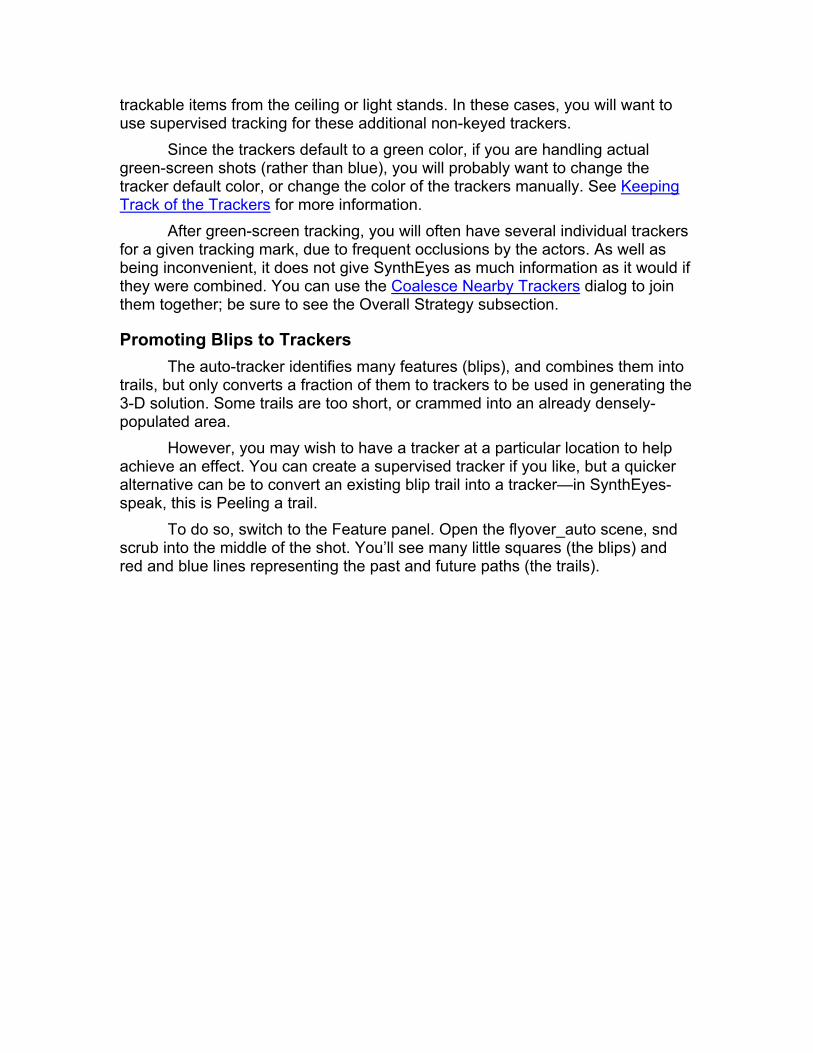
Promoting Blips to Trackers The auto-tracker identifies many features (blips), and combines them into
trails, but only converts a fraction of them to trackers to be used in generating the 3-D solution. Some trails are too short, or crammed into an already densely-populated area.
However, you may wish to have a tracker at a particular location to help achieve an effect. You can create a supervised tracker if you like, but a quicker alternative can be to convert an existing blip trail into a tracker—in SynthEyes-speak, this is Peeling a trail.
To do so, switch to the Feature panel. Open the flyover_auto scene, snd scrub into the middle of the shot. You’ll see many little squares (the blips) and red and blue lines representing the past and future paths (the trails).
You can turn on the Peel button, then click on a blip, converting it to a full
tracker. Repeat as necessary. Alternatively, you can use the Add Many Trackers dialog to do just that in
an intelligent fashion—after an initial shot solution has been obtained.
Keeping Track of the Trackers After an auto-track, you will have hundreds or even thousands of trackers.
To help you see and keep track of them, SynthEyes allows you to assign a color to them, typically so you can group together all the related trackers.
SynthEyes also provides default colors for trackers of different types. Normally, the default color is a green. Separate default colors for supervised, automatic, and zero-weighted trackers can be set from the Preferences panel. You can change the defaults at any time, and every tracker will be updated automatically—except those for which you have specifically set a color.
You can assign the color by clicking the swatch on the Tracker panel, or by double-clicking the miniature swatch at the left of the Lifetimes tracker listing. If you have already created the trackers, lasso-select the group, and shift-click to add to it. Then click the color swatch on the Tracker panel to set the color. On the Lifetimes panel, if you have several selected, shift-double-click the swatch to cause the color of all the trackers in the group to be set. Right-clicking the swatches will set the color back to the default.
If you are creating a sequence of supervised trackers, once you set a color, the same color will be used for each succeeding new tracker, until you

select an existing tracker with a different color, or right-click the swatch to get back to the default.
You will almost certainly want to change the defaults, or set the colors manually, if you are handling green-screen shots.
You will see the tracker colors in the camera view, perspective view, and 3-D viewports, as well as the miniature swatch in the Lifetimes display.
If you have set up a group of trackers with a shared color, you can select the entire group easily: select any tracker in the group, then click the Track/Select all trackers of the same color menu item.
To aid visibility, you can select the Thicker trackers option on the preferences panel. This is particularly relevant for high-resolution displays, where the pixel pitch may be quite small. The Thicker trackers option will turn on by default for monitors over 1300 pixels horizontal resolution.
Note that there are some additional rules that may occasionally override the color and width settings, with the aim of improving clarity and reducing clutter.
Skip-Frame Track The Features panel contains a skip-frame checkbox that causes a
particular frame to be ignored for automatic tracking and solving. Check it if the frame is subject to a short-duration extreme motion blur (camera bump), an explosion or strobe light, or if an actor suddenly blocks the camera.
The skip-frames checkbox must be applied to each individual frame to be skipped. You should not skip more than 2-3 frames in a row, or too many frames overall, or you can make it more difficult to determine a camera solution, or at least create a temporary slide.
You should set up the skip-frames track before autotracking. There is some support for changing the skipped frames after blipping and before linking, but this is not recommended; you may have to rerun the auto-tracking step.
Strengths and Limitations The automatic tracker works best on relatively well-controlled shots with
plenty of consistent spot-type feature points, such as aerial and outdoor shots. Very clean indoor sets with many line features can result in few trackable features. A green-screen with no tracking marks is untrackable, even if it has an actor, since the (moving) actor does not contribute usable trackers.
Rapid feature motion can cause tracking problems, either causing loss of continuity in blip tracks, or causing blips to have such a short lifetime that they are ignored. Use the Crash Pan motion profile to address such shots.
Similarly, situations where the camera spins about its optic axis can exceed SynthEyes expectations.

You can add supervised guide trackers to help SynthEyes determine the frame-to-frame correspondence in difficult shots. A typical example would be a camera bump or explosion with several unusable frames, disabled with the Skip Frames track. If the camera motion from before to after the bump is so large that no trackers span the bump, adding guide trackers will usually give SynthEyes enough information to reconnect the blip trails and generate trackers that span the bump.

Supervised Tracking Solving for the 3-D positions of your camera and elements of the scene
requires a collection of trackers tracked through some or all of the shot. Depending on what happens in your shot, 7 or 8 may be sufficient (at least 6), but a complex shot, with trackers becoming blocked or going off the edge of the frame, can require substantially more. If the automated tracker is unable to produce satisfactory trackers, you will need to add trackers directly. Or, you can use the techniques here to improve automatically-generated ones. Specific supervised trackers can be especially valuable to serve as references for inserting objects, or for aligning the coordinate system as desired.
WARNING: Tracking, especially supervised tracking, can be stressful to body parts such as your fingers, hands, wrists, eyes, and back, like any other detail-oriented computer activity. Be sure to use an ergonometrically sound workstation setup and schedule frequent rest breaks. See Click-on/Click-off mode.
To begin supervised tracking, select the Tracker control panel. Turn on the Create button. Rewind to the beginning of the shot.
Locate a feature to track: a corner or small spot in the image that you could reach in and put your finger on. Do not select a reflective highlight that moves depending on camera location. Left-click on the center of your feature, and while the button is down, position the tracker accurately using the view window on the command panel. The gain and brightness spinners can make shadowed or blown-out features more visible. Adjust the tracker size and aspect ratio to enclose the feature, and a little of the region around it, using either the spinner or inner handle.
Adjust the Search size spinner or outer handle based on how uncertainly the tracker moves each frame. This is a matter of experience. A smooth shot permits a small search size even if the tracker accelerates to a higher rate.
Create any number of trackers before tracking them through the shot. It is easier to do either one or 3-6 at a time.
To track them through the shot, hit the Play or frame forward (>) button (scrubbing does not track). Watch the trackers as you move through the shot. If any get off track, back up a frame or two, and drag them in the image back to the right location. The Play button will stop automatically if a tracker misbehaves, already selected for easy correction.
Prediction Modes and Hand-Held Shots SynthEyes predicts where the feature will appear in each new frame. It
has different ways to do this, depending on your shot. By default, with the two hand-held modes off, it assumes that the shot is smooth, from a steadi-cam, dolly, or crane, and uses the previous history over a number of frames to predict its next position.
If you have a hand-held shot, select Hand-Held: Predict on the Track menu. In this mode, SynthEyes uses other, already-tracked, trackers to predict the location of new ones. Start by tracking a few easy-to-track features that are distributed around the image. You will usually need a large search area, and to re-key fairly frequently if the shot is very choppy. But as you add trackers, you can greatly reduce the search size and will need to set new keys only occasionally as the pattern changes.
Using the predict mode, you’ll sometimes find that a tracker is suddenly way out of position, that it isn’t looking in the right place. If you check your other trackers, you’ll find that one of your previously-tracked trackers is off course on either this or the previous frame. You should unlock that tracker, repair it, relock it, and you’ll see that the tracker you were originally working on is now in the correct place (you may need to back up a frame and then track onto this frame again).
If your shot and the individual trackers are very rough, especially as you are tracking the first few trackers, you may find that the trackers aren’t too predictable, and you can set the mode to Hand-Held: Sticky, in which case SynthEyes simply looks for the feature at its previous location (requiring a comparatively large search region).
Adjusting While Tracking If a tracker goes off course, you can fix it several ways: by dragging it in
the camera view, by holding down the Z key and clicking and dragging in the camera view, by dragging in the small tracker interior view, or by using the arrow keys on the number pad. (Memo to lefties: use the apostrophe/double-quote key ‘/” instead of Z.)
You can keep an eye on a tracker or a few trackers by turning on the Pan to Follow item on the Track menu, and zooming in a bit on the tracker, so you can see the surrounding context. When Pan To Follow is turned on, dragging the tracker drags the image instead, so that the tracker remains centered.
Or, the number-pad-5 key centers the selected tracker whenever you click it.
Staying on Track and Smooth Keying Help keep the trackers on course with the Key N spinner, which places a
tracker key each time the specified number of frames elapses, adapting to changes in the pattern being tracked. If the feature is changing significantly, you may want to tweak the key location each time the key is added automatically. Turn on the Stop on auto-key item on the Track menu to make this easier.
When you reposition a tracker, you create a slight “glitch” in its path that can wind up causing a corresponding glitch in the camera path. To smooth the glitches away, set the Key Smooth spinner to 3, say, to smooth it over the preceding 3 frames. When you set a key, the preceding (3 etc) frames need to be re-tracked. If you turn on Pre-Roll by Key Smooth on the Track menu,

SynthEyes will automatically back up and retrack the appropriate frames when you resume tracking (hit Play) after setting a key.
The combination of Stop on auto-key and Pre-roll by Key Smooth makes for an efficient workflow. You can leave the mouse camped in the tracker view window for rapid position tweaks, and use the space bar to restart tracking to the next automatic key frame. See the web-site for a Flash movie example.
Warning: if SynthEyes is dropping a key every 12 frames, and you want to delete one of those keys because it is bad, it may appear very difficult. Each time you delete (by right-clicking in the tracker view, Now button, or position spinners), a new key will immediately be created. You could just fix it. Or, you should back up a few frames, create a key where the tracker went off-course, then go forward to delete or fix the bad key.
Suspending or Finishing a Track If an actor or other object permanently obscures a tracker, turn off its
enable button, disabling it for the rest of the shot, or until you re-enable it. Trackers will turn off automatically at the edge of the image; turn them back on if the image feature re-appears. (If the shot has a non-image border, use the region-of-interest on the Image Preprocessing panel so that trackers will turn off at the right location.)
You can also track backwards: go to the end of the shot, reverse the playback direction (←), and play or single-step backwards.
You can change the tracking direction of a tracker at any time. For example, you might create a tracker at frame 40 and track it to 100. Later, you determine that you need additional frames before 40. Change the direction arrow on the tracker panel (not the main playback direction, which will change to match). Note that you introduce some stored inconsistency when you do this. After you have switched the example tracker to backwards, the stored track from frames 40-100 uses lower-numbered reference frames, but backwards trackers use higher-numbered reference frames. If you retrack the entire tracker, the tracking data in frames 40-100 will change, and the tracker could even become lost in spots. If you retrack in the new direction, you should continue to monitor the track as it is updated. If you have regularly-spaced keyframes, little trouble should be encountered.
When you are finished with one or more trackers, select them, then click the Lock button. This locks them in place so that they won’t be re-tracked while you track additional trackers.
Combining Trackers You might discover that you have two or more trackers tracking the same
feature in different parts of the shot, or that are extremely close together, that you would like to consolidate into a single tracker.

Select both trackers, using a lasso-select or by shift-selecting them in the camera view or Lifetimes view. Then select the Track/Combine trackers menu item, or the Shift-7 (ampersand &). All selected trackers will be combined, preserving associated constraint information.
If several of the trackers being combined are valid on the same frame, their 2-D positions are averaged. Any data flagged as suspect is ignored, unless it is the only data available. Similarly, the solved 3-D positions are averaged. There is a small amount of intelligence to maintain the name and configuration of the most-developed tracker.
Note: the camera view’s lasso-select will select only trackers enabled on the current frame, not the 3-D point of a tracker that is disabled on the present frame. This is by design for the usual case when editing trackers. Control-lasso to lasso both the 2-D trackers and the 3-D points, or shift-click to select 3-D points.
Filtering and Filling Gaps in a Track To produce even smoother final tracks, instead of Locking the trackers,
click the Finalize button (a hammer). This brings up the Finalize dialog, which filters the tracker path, fills small missing gaps, and Locks the tracker(s). Though filtering can create smoother tracks, it is best used when the camera path is smooth, for example, from a dolly or crane. If the camera was hand-held, smoothing the tracker paths causes sliding, because the trackers will be smoother than the camera!
If you have already begun solving and have a solved 3-D position for a tracker, you can also fill small gaps or correct obvious tracking glitches by using the Exact button on the tracker panel, which sets a key at the location of the tracker’s 3-D position (keyboard: X key, not shifted). You should do this with some caution, since, if the tracking was bad, then the 3-D tracker position and camera position are also somewhat wrong.
Pan To Follow While tracking, it can be convenient to engage the automatic Pan To
Follow mode on the Track menu, which centers the selected tracker(s) in the camera view, so you can zoom in to see some local context, without having to constantly adjust the viewport positioning.
When pan to follow is turned on, when you start to drag a tracker, the image will be moved instead, so that the tracker can remain centered. This may be surprising to begin with.
Once you complete a tracker, you can scrub through the shot and see the tracker crisply centered as the surroundings move around a bit. This is the best way to review the stability of a track.

Skip-Frame Track If a few frames are untrackable due to a rapid camera motion, explosion,
strobe, or actor blocking the camera, you can engage the Skip Frame checkbox on the feature panel to cause the frame to be skipped. You should only skip a few frames in a row, and not that many over all.
The Skip Frames track will not affect supervised tracking, but it affects solving, causing all trackers to be ignored. After solving, the camera will have a spline-interpolated motion on the resulting unsolved frames.
If you have a mixture of supervised and automatic tracking, see the section on the Skip-Frame track in Automated Tracking as changing the track after automated tracking can have adverse effects.

Checking the Trackers SynthEyes provides two displays to help you evaluate how you’re doing at
building up enough trackers for a 3-D solution: the Lifetimes chart and the tracker graph displays. You should also check the tracker trails, as described below.
When you are doing automatic tracking, you should check on the tracker graphs after the initial tracking and solve have completed. The lifetimes chart becomes useful on longer traveling shots, to assess coverage.
When you are doing supervised tracking, you should check on the graphs and lifetimes both before and after solving.
Tip: automatic tracker tooltips have gray backgrounds; supervised trackers have gold backgrounds.
Checking the Tracker Trails The following procedure has proven to be a good way to quickly identify
problematic trackers and situations, such as frames with too few useful trackers. 1. Go to the camera view 2. Turn off View/Show Image on the main or right-click menu. 3. Turn on View/Show tracker trails on the main or right-click menu. 4. Scrub through the shot. Look for trackers moving unexpectedly, or
that have funny hooks at the beginning or end, especially at the edges of the image. Also, look for zig-zag discontinuities in the trails.
Your mind is good at analyzing motion paths without the images — perhaps even better because it is not distracted by the images themselves. This process is helpful in determining the nature of problematic shots, such as shots with low perspective, shots that unexpectedly have been shot on a tripod, tripod shots with some dolly or sway, and shots that have a little zoom somewhere in the middle. Despite the best efforts and record-keeping of on-set supervisors, such surprises are commonplace.
Tracker Graphs The tracker graph viewport helps you find bad trackers and identify the
bad portions of their track. We won’t get to the process of how to find the worst ones until the end of the section, when you understand the viewport. To begin, here we’ve selected a single tracker (Tracker123) as an example.

There are a variety of different curves to remember, but you can always
put the cursor over any curve, and a tool-tip will pop up to identify the tracker and curve type. If you have several trackers selected, clicking a curve will select only that tracker, unselecting the others.
Horizontal Position Red Dotted
Vertical Position Green Dotted
Horizontal Velocity Red Solid
Vertical Velocity Green Solid
2-D Error Blue Solid
3-D Error Blue Dotted
The position values match those from the tracking panel, ranging from -1 to +1. The velocity values are the change in the tracker’s position from the previous frame to this one. The 2-D Error (supervised trackers only) reflects how well the pattern matches the reference.
3-D Error Curve It is important to understand the 3-D error: it is the distance, in pixels,
between the tracker’s 2-D position, and the position in the image of the solved 3-D tracker position. Let’s work this through. The solver looks at the whole 2-D history of a tracker to arrive at a location such as X=3.2, Y=4.5, Z=0.1 for that

tracker. On each frame, knowing the camera’s position and field of view, we can predict where the tracker should be, if it really is at the calculated XYZ. That’s the position at which the yellow X is displayed after solving. The 3-D error is the distance between where the tracker actually is, and the yellow X where it should be. If the tracking is good, the distance is small, but if the tracking has a problem, the tracker is away from where it should be, and the 3-D error is larger. Obviously, given this definition, there’s no 3-D error display until after the scene has been solved.
If you look back at the example, notice that between frames 67 and 73, the blue dotted 3-D error curve jumps way off the top of the chart. Looking at the bottom right, the 4.012 indicates the error corresponding to the top of the chart. If you put the mouse inside the gray E box, you can drag to adjust this. By adjusting the scale until the curve just reaches the top, we can determine that this error tops out around 11 hpixels.
You now know that Tracker123 goes off-course between frames 67 and 73, and needs to be repaired.
Velocity Spikes Further confirmation comes from the solid red and green velocity curves,
particularly the red horizontal velocity. At frame 68, the horizontal curve has a large positive spike, as the tracker jumps right to a very similar feature, and at frame 73, it jumps left, back to the correct feature. The velocity spike is about 0.33, since full scale is 0.100 as marked at the upper right. (The velocity scaling can be adjusted using the gray V at upper right.) That’s about a 12 pixel jump― the search region was made large enough to include this other similar feature to contrive this example.
Learn to recognize these velocity spikes directly. When you do supervised tracking, the 3-D error curve is not available until after solving, but you want to eliminate as many tracking errors as possible before solving… escape this dilemma by looking for velocity spikes and correcting the trackers before solving. There are double spikes when a tracker jumps off course and returns, single spikes when it jumps off course to a similar feature and stays there, large sawtooth areas where it is chattering between near-identical features, or big takeoff ramps where it gets lost and heads off into featureless territory.
Repair by Keying To correct the tracker, click in the timeline to the frame with the spike, then
switch to the camera view. Jiggle back and forth a few frames with the S and D keys to see what’s happening, then unlock the tracker and drop down a new key or two. Step around to re-track the surrounding frames with the new keys (or rewind and play through the entire sequence, which is most reliable). Switch back to re-check the curves. After checking trackers, do a refine solving cycle. It can be quicker to delete extra automatic trackers, rather than repairing them.
In this example, the feature being tracked is relatively stable over time. If you look at the solid blue 2-D error curve, you will see it drop down to zero each

time there is a key (see the timeline at top), and the 2-D error is relatively flat over time, increasing only slightly. You can use this curve to help decide how often to place a key automatically. The 20 frames here is plenty. You’ll also be able to see the effect of the key smoothing setting, as the steady error increase until the next frame will change to a rounded hump.
Blind Repair Using a Tracker Graph Gimmick It is fairly common to want to repair a temporary 1-frame tracker glitch by
averaging from the previous and next frame, or to eliminate a glitchy first or last few frames just be truncating the range of the tracker.
The tracker graph window provides a miniature tool to do this: you can double-click in the tracker graph window on the problematic frame, and if the situation is satisfactory, the frame will be repaired or the track truncated on that frame. Note that you must double-click in the tracker graph window, not in the timing bar. Generally you should zoom in to see the frames clearly in the timing bar before attempting a repair.
Often, you will want to repair a tracker that is locked, which is generally a no-no. However, the little repair tool checks the SHIFT key when you double-click—if the shift key is pushed, it will unlock the tracker, repair it, and relock it! Although it may seem a pain to constantly push the shift key, this solves the problem where you mistakenly and unknowingly double-click and clobber one of your trackers.
If the repair tool does not detect a situation that it addresses (including a locked tracker, but the shift key is not depressed), it will beep to notify you of the difficulty.
The tool does have some side effects. For example, if you use it to truncate the first frame of a (forward-tracking) supervised tracker because it is bad, it will set a key at the second frame in the range, if there is none, to provide a keyframe for the following (supervised-tracked) frames. Of course, if the first frame was bad, the second is likely to be not-so-good either.
Sorting by Error Back to the original objective: how can we find the worst trackers quickly?
One easy way is to go to the tracker graph display and hit control/command-A to select ALL of the trackers. Then, look for 3-D error curves that spike off the top of the viewport, or the biggest velocity spikes if the scene hasn’t been solved yet. Click on each suspicious-looking curve to isolate that tracker and investigate further. You can turn off View/Show Tracker Positions to reduce clutter.
If you have already solved the scene, you can also click View/Sort by Error, control/command-D to deselect everything, and then the down arrow to advance to the most erroneous tracker. Continue using the down arrow to sweep through the noisiest trackers.
Either way, the tracker graph will help you pinpoint problematic areas. The Tracker & Camera viewport configuration may also you do this rapidly.

Lifetimes Panel You can overview how many trackers are available on each frame
throughout the shot with the Lifetimes control panel and viewport (technically a Gantt chart). It lists the trackers and shows their keys and where they are valid. Select Sort Alphabetic or Sort by Error on the View menu, or they will be sorted by time. Sorting by time helps particularly on long shots.
Use the mouse scroll wheel to move forwards/backwards a frame at a
time in the bar graph. SynthEyes displays the frame and number of active trackers (7 frames and 44 trackers above). If there are too few valid trackers, the background will turn yellow or red for those frames. (Zero-weighted trackers don’t count.)
You can also configure a “safe” level on the preferences. Above this limit (default 12), the background will be white (gray for the dark UI setting), but below the safe limit, the background will be the safe color (configurable as a standard preference), which is typically a light shade of green: the number of trackers is OK, but not high enough to hit your desired safe limit.
If there are unavoidably too few trackers on some frames, you can use the Skip Frames track on the Feature Panel to proceed.
You can select trackers by clicking their bar in the Lifetimes viewport or control panel. You can control-click to toggle selections, or shift-drag to select a range. Here, Tracker2 is selected.
The small swatch along the left edge shows the display color; here Tracker2 is blue. Double-clicking brings up the color selection dialog so you can change the display color. If you have several trackers to change at once, shift-double-click to avoid deselecting them. Right-clicking will set the color back to the default color.
Double-clicking the red/green circles in the control panel locks or unlocks the tracker(s): only Tracker4 is unlocked in this example.
Jumping ahead, the Lifetime control panel also shows any coordinate-system lock settings for each tracker:
x, y, and z for the respective axis constraints; l (lower-case L) when there is a linked tracker on the same object; i for a linked tracker on a different object (an indirect link);

d for a distance constraint; 0 for a zero-weighted tracker; p for a pegged tracker; f for far trackers.
In the main lifetimes display, as well as the selection modes described above, you can delete keys from many trackers at once over a range of times by ALT-dragging: all keys in the enclosed rectangle will be deleted. Important: the trackers must be unlocked, or the delete won’t have any effect.
You can select a viewport configuration that shows the tracker graph or Lifetimes viewports at the same time as you are tracking in the camera window.

Setting Up a Coordinate System You will usually want to tell SynthEyes how to orient, position, and size the
trackers and camera path in 3-D. Historically, people learning tracking have had a hard time with this because they do not understand what the problem is, or even that there is a problem at all. If you do not understand what the problem is, what you are trying to do, it is pretty unlikely you will understand the tools that let you solve it. What follows is an attempt to give you a tangible explanation. It’s silly, but please read carefully!
SynthEyes and the Coordinate Measuring Machine Pretend SynthEyes is a 2D-to-3D-converting black box on your desk that
manufactures a little foam-filled architectural model of the scene filmed by your shot. This little model even has a little camera on a track showing exactly where the original camera went, and for each tracker, a little golf pole and flag with the name of the tracker on it.
Obviously SynthEyes is a pretty nifty black box. One problem, though: the foam-filled model is not in your computer yet. It fell out of the output hopper, and is currently sitting upside down on your desk.
Fortunately, you have a nifty automatic coordinate measuring machine, with a little robot arm that can zip around measuring coordinates and putting them into your computer.
You open the front door of the coordinate measuring machine and see the inside looks like the inside of a math teacher’s microwave oven, with nice graph-paper coordinate grids on the inside of the door, bottom, top, and sides, and you can see through the glass sides if you look carefully. Those are the coordinates measured by the machine, and where things will show up at inside your animation package. The origin is smack in the middle of the machine.
So you think “Great”, casually throw your model, still upside-down, into the measuring machine, and push the big red button labeled “Good enough!” The machine whirs to life and seconds later, your animation package is showing a great rendition of your scene—sitting cock-eyed upside down in the bottom of your workspace. That is not what you wanted at all, but hey! That’s what you got just throwing your model into the measuring machine all upside down.
You open up the door, pull out your model, flip it over, put it back in, and close the door. Looking at the machine a little more carefully, you see a green button labeled “Listen up” and push it. Inside, a hundred little feet march out a small door, crawl under the model, and lift it up from the bottom of the machine.
Since it is still pretty low, you shout “A little higher, please.” The feet cringe a little—maybe the shouting wasn’t necessary—but the little feet lift your model a bit higher. That’s a good start, but now “More to the right. Even some more.” You’re making progress, it looks like the model might wind up in a better place now. You try “Spin around X” and sure enough the feet are pretty clever. After

about ten minutes of this, though the model is starting to have its ground plane parallel to the bottom of the coordinate measuring machine, you’ve decided that the machine is really a much better listener than you are a talker, and you have learned why the red button is labeled “Good enough!” Giving up, you push it, and you quickly have the model in your computer, just like you had positioned it in the machine.
Hurrah! You’ve accomplished something, albeit tediously. This was an example of Manual Alignment: it is usually too slow and not too accurate, though it is perfectly feasible.
Perhaps you haven’t given the little feet enough credit. Vowing to do better, you try something trickier: “Feet, move Tracker37 to
the origin.” Sure enough, they are smarter than you thought. As you savor this success, you notice the feet starting to twiddle their toes.
Apparently they are getting bored. This definitely seems to be the case, as they slowly start to push and spin your model around in all kinds of different directions.
All is not lost, though. It seems they have not forgotten what you told them, because Tracker37 is still at the origin the entire time, even as the rest of the model is moving and spinning enough to make a fish sea-sick. Because they are all pushing and pulling in different directions, the model is even pulsing bigger and smaller a bit like a jellyfish.
Hoping to put a stop to this madness, you bark “Put Tracker19 on the X axis.” This catches the feet off guard, but once they calm down, they sort it out and push and pull Tracker19 onto the X axis.
The feet have done a good job, because they have managed to get Tracker19 into place without messing up Tracker37, which is still camped at the origin.
The feet still are not all on the same page yet, because the model is still getting pushed and pulled. Tracker37 is still on the origin, and Tracker19 is on the X axis, but the whole thing is pulsing bigger and smaller, with Tracker19 sliding along the axis.
This seems easy enough to fix: “Keep Tracker37 at X=20 on the X axis.” Sure enough, the pulsing stops, though the feet look a bit unhappy about it. [You could say “Make Tracker23 and Tracker24 15 units apart with the same effect, but different overall size.]
Before you can blink twice, the feet have found some other trouble to get into: now your model is spinning around the X axis like a shish-kebab on a barbecue rotisserie. You’ve got to tell these guys everything!
As Tracker5 spins around near horizontal, you nail it shut: “Keep Tracker5 on the XY ground plane.” The feet let it spin around one more time, and grudgingly bring your model into place. They have done everything you told them.
You push “Good enough” and this time it is really even better than good enough. The coordinate-measuring arm zips around, and now the SynthEyes-generated scene is sitting very accurately in your animation package, and it will be easy to work with.
Because the feet seemed to be a bit itchy, why not have some fun with them? Tracker7 is also near the ground plane, near Tracker5, so why not “Put Tracker7 on the XY ground plane.” Now you’ve already told them to put Tracker5 on the ground plane, so what will they do? The little feet shuffle the model back and forth a few times, but when they are done, the ground plane falls in between Tracker5 and Tracker7, which seems to make sense.
That was too easy, so now you add “Put Tracker9 at the origin.” Tracker37 is already supposed to be at the origin, and now Tracker9 is supposed to be there too? The two trackers are on opposite sides of the model! Now the feet seem to be getting very agitated. The feet run rapidly back and forth, bumping into each other. Eventually they get tired, and slow down somewhere in the middle, though they still shuffle around a bit.
As you watch, you see small tendrils of smoke starting to come out of the back of your coordinate measuring machine, and quickly you hit the Power button.
Back to Reality Though our story is far-fetched, it is quite a bit more accurate than you
might think. Though we’ll skip the hundred marching feet, you will be telling SynthEyes exactly how to position the model within the coordinate system.
And importantly, if you don’t give SynthEyes enough information about how to position the model, SynthEyes will take advantage of the lack of information: it will do whatever it finds convenient for it, which rarely will be convenient for you. If you give SynthEyes conflicting information, you will get an averaged answer—but if the information is sufficiently conflicting, it might take a long time to provide a result, or even throw up its hands and generate a result that does not satisfy any of the constraints very well.
There are four main methods for setting up the coordinates, which we will discuss in following sections:
• Manually
• Using the 3-point method
• Configuring trackers individually
• Alignment Lines The alignment line approach is used for tripod-mode and even single-
frame lock-off shots.

One last point: you might wonder how any of the tracker numbers get decided on: Tracker37, Tracker19, etc. You will pick the trackers to create the coordinate system that you want to see in the animation/compositing package.
You must decide what you want! If the shot has a floor and you have trackers on the floor, you probably want those trackers to be on the floor in your chosen coordinate system. Your choice will depend on what you are planning to do later in your animation or compositing package. It is very important to realize: the coordinate system is what YOU want to make your job easier. There is no correct answer, there is no coordinate system that SynthEyes should be picking if only it was somehow smarter…They are all the same. The coordinate measuring machine is happy to measure your scene for you, no matter where you put it! You don’t need to set a coordinate system up, if you don’t want to, and SynthEyes will plough ahead happily. But picking one will usually make inserting effects later on easier. You can do it either after tracking and before solving, or after solving.
Three-Point Method Here’s the simplest and most widely applicable way to set up a coordinate
system. It is strongly recommended unless there is a compelling reason for an alternative. SynthEyes has a special button to help make it easy. We’ll described how to use it, and what it is doing, so that you might understand it, and be able to modify its settings as needed.
Switch to the Coordinate System control panel. Click the *3 button; it will now read Or. Pick one tracker to be the coordinate system origin (ie at X=0, Y=0, Z=0). Select it in the camera view, 3-D viewport, or perspective window. On the coordinate system panel, it will automatically be changed from Unlocked to Origin. Again, any tracker can be made the origin, but some will make more sense and be more convenient than others.
The *3 button will now read LR (for left/right). Pick a second tracker to fall along the X axis, and select it. It will automatically be changed from Unlocked to Lock Point; after the solution it will have the X/Y/Z coordinates listed in the three spinners. Decide how far you want it to be from the origin tracker, depending on how big you want the final scene to be. Again, this size is arbitrary as far as SynthEyes is concerned. If you have a measurement from the set, and want a physically-accurate scene, this might be a place to use the measurement. One way or another, decide on the X axis position. You can guess if you want, or you can use the default value, 20% of the world size from the Solver panel. Enter the chosen X-axis coordinate into the X coordinate field on the control panel.
The *3 button now reads Pl. Pick a third point that should be on the ground plane. Again, it could be any other tracker―except one on the line between the origin and the X-axis tracker. Select the tracker, and it will be changed from Unlocked to On XY Plane (if you are using a Z-Up coordinate system, or On XZ Plane for Y-up coordinates). This completes the coordinate system setup, so the *3 button will turn off.
The sequence above places the second point along the X axis, running from left to right in the scene. If you wish to use two trackers aligned stage front to stage back, you can click the button from LR (left/right) to FB (front/back) before clicking the second tracker. In this case, you will adjust the Y or Z coordinate value, depending on the coordinate system setting.
To provide the most accurate alignment, you should select trackers spread out across the scene, not lumped in a particular corner, say.
Depending on your desired coordinate system, you might select other axis and plane settings. You can align to a back wall, for example. For the more complex setups, you will adjust the settings manually, instead of using *3.
You can lock multiple trackers to the floor or a wall, say if there are tracking marks on a green-screen wall. This is especially helpful in long traveling shots. If you are tracking objects on the floor, track the point where the object meets the floor; otherwise you’ll be tracking objects at different heights from the floor (more on this in a little).
Size Constraints As well as the position and orientation of your scene, you need to control
the size of the reconstructed scene. There are two general ways to do this: 1) Have two points that are locked to (different) xyz coordinates,
such as an origin (0,0,0) and a point at (20,0,0), as in the recommended method described above, or,
2) With a distance (size) constraint between two points. If you want to use one collection of trackers to position and align the
coordinate system, but use an on-set measurement between two other trackers, you can use a distance constraint.
You can set up the distance constraint as follows. Suppose you have two trackers, A and B, and want them 20 units apart, for example. Open the coordinate system control panel. Select tracker A, ALT-click (Mac: Command-click) on tracker B to set it as the target of A. Set the distance (Dist.) spinner to 20.
Note: if you set up a distance constraint and have used the *3 tool, you should select the second point, which is locked to 20,0,0, and change its mode to On X Axis (On Y Axis for front/back setups). Otherwise, you will have set up two size constraints simultaneously, and unless both are right, you will be causing a conflict.
Configuring Constraints Directly Each tracker has individual constraints that can be used to control the
coordinate system, accessed through the Coordinate System Control panel. The *3 button automatically configures these controls for easy use, but you can manually configure them to achieve a much wider variety of effects—if you keep in mind the mental picture of the busy little feet in the coordinate measuring

machine. Those feet do whatever you tell them, but are happy to wreak havoc in any axis you do not give them instructions for.
As examples of other effects you can achieve, you can use the Target Point capability to constrain two points to be parallel to a coordinate axis, in the same plane (parallel to XY, YZ, or XZ), or to be the same. For example, you can set up two points to be parallel to the X axis, two other points to be parallel to the floor, and a fifth point to be the origin.
Suppose you have three trackers that you want to define the back wall (Z up coordinate system).
1) Go to the coordinate system control panel 2) If the three trackers are A, B, and C, select B, then hold down
ALT (Mac: Command) and click A. 3) Change the constraint type from Unlocked to Same XZ plane. 4) Select C, and ALT-click (Command) on A, and set it to Same XZ
Plane also. This has nailed down the translation, but rotation only partially—the feet
will be busy. You also need to specify another rotation, since B and C can spin freely around A so far (or around the Y axis about any point in the plane).
You might have two other trackers, D and E, that should stack up vertically. Select E and Alt/Command-Click D and set to Parallel to Z Axis (or X axis if they should be horizontal).
Fine point: when you set up the coordinate system, you should adjust the camera in 3-D so it is roughly positioned and oriented correctly for the first frame. Otherwise you can wind up with the camera upside down underneath the set ― which is an equally valid camera placement, but not usually the one you want!
Details of Lock Modes There are quite a few different constraint (lock) modes that can be
selected from the drop-down list. Despite the fair number of different cases, they all can be broken down to answering two simple questions: (1) which coordinates (X, Y, and/or Z) of the tracker should be locked, and (2) to what values.
The first question can have one of eight different answers: all the combinations of whether or not each of the three coordinate axes is locked, ranging from none (Unlocked) to all (Lock Point). Rather than listing each of the combinations of which axes are locked, the list really talks about which axis is NOT locked. For example, an X Axis lock really locks Y and Z, leaving X unlocked. Locking to the XZ plane actually locks only Y. The naming addresses WHAT you want to do, not HOW you will achieve it.
The second question has three possible answers: (a) to zero, (b) to the corresponding “Seed and Lock” spinner, or (c) the corresponding coordinate from the tracker assigned as the Target Point. Answer (c) is automatically selected if a target point is present, while (a) is selected for “On” lock types, and (b) for “Any”

lock types. Use the Any modes when you have some particular coordinates you want to lock a tracker to, for example, if a tracker is to be placed 2 units above the ground plane.
Here’s the total list:
Lock Mode Axes Locked To What
Unlocked None Nothing
Lock Point X,Y,Z Spinners
Origin X, Y, Z Zero
On X Axis Y, Z Zero
On Y Axis X, Z Zero
On Z Axis X, Y Zero
On XY Plane Z Zero
On XZ Plane Y Zero
On YZ Plane X Zero
Any X Axis Y, Z Spinners
Any Y Axis X, Z Spinners
Any Z Axis X, Y Spinners
Any XY Plane Z Spinners
Any XZ Plane Y Spinners
Any YZ Plane X Spinners
Identical Place X, Y, Z Target
|| X Axis Y, Z Target
|| Y Axis X, Z Target
|| Z Axis X, Y Target
Same XY Plane Z Target
Same XZ Plane Y Target

Lock Mode Axes Locked To What
Same YZ Plane X Target
Configuring Constraints for Tripod-Mode Shots When the camera is configured in tripod mode, a simpler coordinate-
system setup can be used. In tripod mode, no overall sizing is required, and no origin is required or allowed. The calculated scene must only be aligned, though even that is not always necessary.
The simplest tripod alignment scheme relies on finding two trackers on the horizon, or at least that you’d like to make the horizon. Of the two, you assign one to be the X axis, say, by setting it up as a Lock to the coordinates X=100, Y=0, Z=0, for the normal World Size of 100. If the world size was 250, the lock point would be 250, 0, 0 : a Far tracker should always be locked to coordinates where X squared plus Y squared plus Z squared equals the world size squared. It is not necessary for the constraint to work correctly, but for it to be displayed correctly.
With one axis nailed down, the other tracker only needs to be labeled “On XY plane,” say (or XZ in Y-Up coordinates).
Tip: if you have a tripod shot that pans a large angle, 120 degrees or more, small systematic errors in the camera, lens, and tracking can accumulate to cause a banana-shaped path. To avoid this, set up a succession of trackers along the horizon or another straight line, and peg them in place.
Constrained Points View After you have set up your constraints, you should check your work using
the Constrained Points viewport layout, as shown here:
This is the view with the recommended constraint setup, as applied to a
typical shot, after solving. Only trackers with constraints are listed, along with what they are locked to (coordinates or another tracker). The solved position is shown, along with the 3-D error of the constraint. For example, if a tracker is located at (1,0,0) but is locked to (0,0,0), the 3-D error will be 1. It will have a completely different 2-D error in hpix on the coordinate system panel.
The constrained points view lets you check your constraints after solving, giving you the resulting 3-D errors, or check your setup before solving, without any error available yet. You can select the trackers directly from this view and tweak them with the coordinate system panel displayed.
Subtleties and Pitfalls The locks between two trackers are inherently bidirectional. If you lock A
to B, do not lock B to A. Similarly, avoid loops, such as locking A to B, B to C, and C to A.
If you want to lock A, B, C, and D all to be on the same ground plane with the same height, say, it is enough to lock B, C, and D all to A.
When you choose coordinates, you should keep the scene near the origin. If your scene is 2000 units across, but it is located 100000 units from the origin, it will be inconvenient to work with, and runs the risk of some numeric issues. This can happen after importing scene coordinates based on GPS readings. You can use the Track/Shift Constraints tool to offset the scene back towards the origin.
Alignment Versus Constraints With a small, well-chosen, set of constraints, there will be no conflict
among them: they can all be satisfied, no matter the details of the point coordinates. This is the case for the 3-tracker recommended method.
However, this is not necessarily the case: you could assign two different points to both be the origin. Depending on their relative positions, this may be fine, or a mistake.
SynthEyes has two main ways to approach such conflicts: treating the coordinate system constraints as suggestions, or as requirements, as controlled by the Constrain checkbox on the Solver control panel.
For a more useful example, consider a collection of trackers for features on the set floor. You can apply constraints telling SynthEyes that the trackers should be on the floor, but some may be paint spots, and some may be pieces of trash a small distance above the floor.
With the Constrain box off, SynthEyes solves the scene, ignoring the constraints, then applies them at the end, only by spinning, rotating, and scaling the scene. In the example of trackers on a floor, the trackers are brought onto an average floor plane, without affecting their relative positions. The model is fundamentally not changed by the constraints.
On the other hand, with the Constrain checkbox on, the constraints are applied to each individual tracker during the solving process. Applied to trackers on a floor, the vertical coordinate will be driven towards zero for each and every such tracker, possibly causing internal conflict within the solving process.
If you have tracked 3 shadows on the floor, and the center of one tennis ball sitting on the floor, you have a problem. The shadows really are on the floor, but the ball is above it. If all four height values are crunched towards zero, they will be in conflict with the image-based tracking data, which will be attempting to place the tennis ball above the shadows.
You can add poorly chosen locks, or so many locks, that solving becomes slower, due to additional iterations required, and may even make solving

impossible, especially with lens distortion or poor tracking. By definition, there will always be larger apparent errors as you add more locks, because you are telling SynthEyes that a tracker is in the wrong place. There is less difference between the error value of the correct solution and the error of incorrect solutions. Not only are the tracker positions affected, but the camera path and field of view are affected, trying to satisfy the constraints. So don’t add locks unless they are really necessary.
Generally, it will be safer to leave the Constrain checkbox off, so that solving is not adversely affected by incorrectly configured constraints. You will want to turn the checkbox on when using multiple-shot setups with the Indirectly solving method, or if you are working from extensive on-set measurements. It must be on to match a single frame.
Pegged Constraints With the constraints checkbox on, SynthEyes attempts to force the
coordinate values to the desired values. It can sometimes be helpful to force the coordinates to be exactly the specified value, by turning on the Peg button on the tracker’s Coordinate system panel.
Pegs are useful if you have a pre-existing scene model that must be matched exactly, for example, from an architectural blueprint, a laser-rangefinder scan, or from global positioning system (GPS) coordinates. Pegging GPS coordinates is especially useful in long highway construction shots, where overall survey accuracy must be maintained over the duration of the shot.
Pegs are active only when the Constrain checkbox is on, and you can only peg to numeric coordinates or to a tracker on a different camera/object, if the tracker’s camera/object is Indirectly solved. You can not peg to a tracker on the same camera/object, this will be silently ignored.
The 3-D error will be zero when you look at a pegged tracker in the Constrained Points view. However, the error on the coordinate system or tracking panel, as measured in horizontal pixels, will be larger! That is because the peg has forced the point to be at a location different than what the image data would suggest.
Constrain Mode Limitations and Workflow The constrain mode has an important limitation, while initially solving a
shot in Automatic solving mode: enough constrained points must be visible on the solving panel’s Begin and End frames to fully constrain the shot in position and orientation. It can not start solving the scene and align it with something it can not see yet, that’s impossible!
SynthEyes tries to pick Begin and End frames where the constrained points are simultaneously visible, but often that’s just not possible when a long shot moves through an environment, such as driving down a road. The error message “Can’t locate satisfactory initial frames” will be produced, and solving will stop.

In such cases, the Constrain mode (checkbox) must be turned off on the solving panel, and a solution will easily be produced, since the alignment will be performed on the completed 3-D tracker positions.
You can now switch to the Refine solving mode, turn on the Constrain checkbox, and have your constraints and pegs enforced rigorously. As long as the constraints aren’t seriously erroneous, this refine stage should be quick and reliable.
Here’s a workflow for complex shots with measured coordinates to be matched:
1. Do the 2-D tracking (supervised or automatic) 2. Set up your constraints (if you have a lot of coordinates, you can
read them from a file). 3. Do an initial solve, with Constrain off. 4. Examine the tracker graphs, assess and refine the tracking 5. Examine the constrained points view to look for gross errors
between the calculated and measured 3-D locations, which are usually typos, or associating the 3-D data with the wrong 2-D tracker. Correct as necessary.
6. Change the solver to Refine mode 7. Turn on the Constrain checkbox 8. Solve again, verify successful. 9. Turn on the Peg mode for tracker constraints that must be achieved
exactly. 10. Solve again 11. Final checks that pegs are pegged, etc.
With this approach, you can use Constrain mode even when constrained trackers are few and far between, and you get a chance to examine the tracking errors (in step 4) before your constraints have had a chance to affect the solution (ie possibly messing it up, making it harder to separate bad tracking from bad constraints.)
Note: if you have survey data that you are matching to a single frame, you must use Seed Points mode and you must turn on Constrain.
Tripod and Lock-off Shot Alignment Tripod-mode shots provide special issues for alignment, since by their
nature, a full 3-D solution is not available. Tripod shot tracking provides the pan, tilt, and roll of the camera versus time, and the direction to the trackers, but not the distance to the trackers. So if you need to place objects in the shot in 3-D, it can be difficult to know where to place them. The good news is that wherever

you put them, they will “stick,” so the primary concern is to locate items so that they match the perspective of the shot.
SynthEyes contains a perspective-matching tool to help, with the requirement that your shot contain several straight lines. Depending on the situation, two or more must be parallel. Here’s an example:
There are parallel lines under the eaves and window, configured to be
parallel to the X axis. Vertical (Z) lines delineate edges of the house and door frame. The selected line by the door has been given a length to set the overall scale.
The alignment tool gives you camera placements and FOV for completely locked-off shots, even a single still photograph such as this.
What Lines Do I Need? The alignment solver can be used after a shot has been solved and a lens
field of view (FOV) determined; it might be used without a solve, with a known FOV; or it might be used to determine the lens FOV. In each case it will determine the camera placement as well.
If the FOV is known, either from a solve or an on-set measurement, you will need to set up at least two lines, which must be parallel to two different coordinate axes in 3-D (X, Y, or Z). This means they must not be parallel to each other (because then they would be parallel to the same axis). You may have any number of additional lines.
When the FOV is not known, you must define at least three lines. Two of them must be parallel to each other and to a coordinate-system axis. The third

line must be parallel to a different coordinate system axis. You may have additional lines parallel to any of the three coordinate system axes.
Note: SynthEyes permits unoriented lines to be used to help find the lens distortion. Unoriented lines do not have to be aligned with any of the desired coordinate system axes—but do not count at all towards the count of lines required for alignment.
Whether the FOV is known to start or not, two of the lines on different axes must be labeled as on-axis, meaning that the scene will be moved around until those lines fall along the respective axis. For example, you might label one line as On X Axis and another as On Y Axis. If you do not have enough on-axis lines, SynthEyes will assign some automatically, though you should review those choices.
The intersection of the on-axis lines will be the origin of the coordinate system. In the example above, the origin will be at the bottom-right corner of the left-most of the two horizontal windows above the door. As with tracker-based coordinate system setup, there is no “correct” assignment—the choice is up to you to suit the task at hand.
To maximize accuracy, parallel lines should be spread out from one another: two parallel lines that are right next to each other do not add much independent information. If you bunch all the lines on a small object in a corner of the image, you are unlikely to get any usable results. We can not save you from a bad plan!
It is better if the lines are spread out, with parallel lines on opposing sides of the image, and even better if they are not parallel to one another in the image. For example, the classis image of railroad tracks converging at the horizon provides plenty of information.
Also, be alert for situations where lines appear to be parallel or perpendicular, but really are not. For example, wooden sets may not really be geometrically accurate, as that is not normally a concern (they might even have forced perspective by design!). Skyscrapers may have slight tapers in them for structural reasons. The ground is usually not perfectly flat. Resist the temptation to “eyeball” some lines into a shot whenever possible. Though plenty of things are pretty parallel or perpendicular, keep in mind that SynthEyes is using exact geometry to determine camera placement, so if the lines are not truly right, the camera will come out in a different location because of it.
Operating the Panel To use the alignment system, switch to the Lens Control panel. Alignment
lines are displayed only when this panel is open. Go to a frame in your sequence that nicely shows the lines you plan to use
for alignment. All the lines must be present on this single frame, and this frame number will be recorded in the “At nnnf” button at the lower-left of the lens panel. You can later return to this frame just by clicking the button. If you later play with

some lines on a different frame, and need to change the recorded frame number, right-click the button to set the frame number to the current frame.
Click on the Add Line button, then click, drag, and release in the camera view to create a line in the image. When you release, a menu will appear, allowing you to select the desired type of line: plain, parallel to one of the coordinate axes, on one of the coordinate axes, or on an axis, with the length specified. Specify the type desired, then continue adding lines as needed. Be sure you check your current coordinate-axis setting in SynthEyes (Z-Up, Y-Up, or Y-Up-Left), so that you can assign the line types correctly. You should make the lines as long as possible to improve accuracy, as long as the image allows you to place it accurately.
Lines that are on an axis must be drawn in the correct direction: from the negative coordinate values to the positive coordinate values. For example, with SynthEyes in Z-Up coordinate mode, a line specified as “On Z Axis” should be drawn in the direction from below ground to above ground. There will be an arrow at the above ground end, and it should be point upwards. But don’t worry if you get it wrong, you can click the swap-end button <-> to fix it instantly.
It does not matter in what direction you draw lines that are merely parallel to an axis, not on it. The arrowhead is not drawn for lines parallel to the axis.
To control the overall sizing of the scene, you can designate a single on-axis line to have a length. Again, this line must be on an axis, not merely parallel to it. After creating the line, select one of the “on-axis with length” types. This will activate the Length spinner, and you can dial in the desired length.
Before continuing to the solution, be sure to quickly zoom in on each of the alignment lines endpoints, to make sure they are placed as accurately as possible. (Zooming into the middle will tell you if you need to engage the lens distortion controls, which will complicate your workflow.) You can move either endpoint or even the whole line, and adjust the line type at any time.
After you have completed setting up the alignment lines, click the Align! button. SynthEyes will calculate the camera position relative to the origin you have specified, and if the scene is not already solved and parallel lines are available, SynthEyes will also calculate the field of view.
A total alignment error will be listed on the status line at the bottom of the SynthEyes window. The alignment error is measured in root-mean-square horizontal pixels like the regular solver. A value of a pixel or two is typical. If you do not have a good configuration of lines, an error of hundreds of pixels could result, and you must re-think.
SynthEyes will take the calculated alignment and apply it to an existing solution, such that the camera and origin are at their computed locations on the frame of reference (indicated in the At nnnf button). Suppose you are working on, and have solved, a 100-frame tripod-mode shot. You have built the alignment lines on frame 30. When you click Align!, SynthEyes will alter the entire path,

frames 0-99, so that the camera is in exactly the right location on frame 30, without messing up the camera match before or after the frame.
Most meshes will not be affected by the alignment, so that they can be used as references. To make them move, turn on Whole affects meshes on the 3-D viewport and perspective-view’s right-click menus.
You should switch to the Quad view and create an object or two to verify that the solution is correct.
If the quality of the alignment lines you have specified is marginal, you may find SynthEyes does not immediately find the right solution. To try alternatives, control-click the Align! button. SynthEyes will give you the best solution, then allow you to click through to try all the other (successively worse) solutions. If your lines are only slightly off-kilter, you may find that the correct solution is the second or maybe third one, with only a slightly higher RMS error.
Advanced Uses and Limitations Since the line alignment system is pretty simple to understand and use,
you might be tempted to use it all the time, to use it to align regular full 3-D camera tracking shots as well. And in fact, as its use on tripod-mode shots suggests, we have made it usable on regular moving camera and even moving-object shots, which are an even more tempting use.
But even though it works fine, it probably is not going to turn out the way you expect, or be a usable routine alternative to tracker constraints for 3-D shots.
First, there’s the accuracy issue. A regular 3-D moving-camera shot is based on hundreds of trackers over hundreds of frames, yielding many hundreds of thousands of data points. By contrast, a line alignment is based on maybe ten lines, hand-placed into one frame. There is no way whatsoever for the line-based alignment to be as accurate as the tracker solutions. This is not a bug, or an issue to be corrected next week. Garbage in, garbage out.
Consequently, after your line-based alignment, the camera will be at one location relative to the origin, but the trackers will be in a different (more correct) position relative to the camera, so…. The trackers will not be located at the origin as you might expect. Since the trackers are the things that are locked properly to the image, if you place objects as you expect into the alignment-determined coordinate system, they will not stick in the image—unless you tweak the inserted object’s position to make them match better to the trackers, not the aligned coordinate system.
Second, there is the size issue. When you set up the size of the alignment coordinate, it will position the camera properly. But it will have nothing to say about the size of the cloud of trackers. You can have the scene aligned nicely for a 6-foot tall actor, but the cloud of trackers is unaffected, and still corresponds to 30 foot giants. To have any hope of success using alignment with 3-D solves, you must still be sure to have at least a distance constraint on the trackers. This is even more the case with moving-object shots, where the independent sizing of the camera and object must be considered, as well as that of the alignment lines.

The whole reason that the alignment system works easily for tripod and lock-off shots is that there is no size and no depth information, so the issue is moot for those shots.
To summarize, the alignment subsystem is capable of operating on moving-camera and moving-object shots, but this is useful only for experts, and probably is not even a good idea for them. If you send us a your scene file at tech support looking for help on that, we are going to tell you not to do it, to use tracker constraints instead, end of story.
But, you should find the alignment subsystem very useful indeed for your tripod-mode and lock-off shots!
Manual Alignment You can manually align the camera and solved tracker locations if you
like. This technique is most useful for tripod-mode shots; it is generally better to set up an accurate coordinate system using the methods above for normal shots.
To align manually, switch to the 3-D control panel and the Quad or Quad Perspective view. Select the camera in one of the viewports, so that it is listed in the dropdown on the 3-D control panel (usually Camera01). It will be easiest, though not strictly necessary, to turn on the selection-lock button right underneath the dropdown.
Turn on the Whole button on the 3-D control panel, then use the move, rotate, and scale tools to reposition the camera using the viewports. As you do this, not only the camera will move, but its entire trajectory and the tracker locations.
By default, meshes will not be carried along, so that you can import a 3-D model (such as a new building), then reposition the camera and trackers relative to the building’s (fixed) position. However, you can turn on Whole affects meshes, on the 3-D viewport and perspective-view right-click menus, and meshes will be moved.
You can use the same technique for moving-object shots, discussed later. In that case, you will usually click the World button to change to Object coordinates; you can then re-align the object’s coordinate system relative to the object’s trackers (much like you move the pivot point in a 3-D model). As you do this, the object path will change correspondingly to maintain the overall match.
Using 3-D Survey Data Sometimes you may be supplied with exact 3-D coordinates for a number
of features in the shot, as a result of hand measurements, laser scans, or GPS data for large outdoor scenes. You may also be supplied with a few ruler measurements, which you can apply as size constraints; we won’t discuss that further here, but will focus on some aspects of handling 3-D coordinates. The full details continue in following sections.
First, given a lot of 3-D coordinates, it can be convenient to read them in automatically from a text file, see the manual’s section on importing points.
SynthEyes gives you several options for how seriously the coordinate data is going to be believed. Any 3-D data taken by hand with a measuring tape for an entire room should be taken as a suggestion at best. At the other end of the spectrum, coordinates from a 3-D model used to mill the object being tracked, or laser-surveyed highway coordinates, ought be interpreted literally.
Trackers with 3-D coordinates, entered manually or electronically, will be set up as Lock Points, so that X, Y, and Z will be matched. Trackers with very exact data will also be configured as Pegs, as described later.
If the 3-D coordinates are measured from a 2-D map (for a highway or architectural project), elevation data may not be available. You should configure such trackers as Any Z (Z-up coordinates) or Any Y (Y-up coordinates), so that the XY or XZ coordinates will be matched, and the elevation allowed to float.
If most of your trackers have 3-D coordinates available to start (six or more per frame), you can use Seed Points solving mode. Turn on the coordinate system panel’s Seed button for the trackers with 3-D coordinates. This will give a quick and reliable start to solving. You must use Seed Points and Constrain modes if you are matching a single frame from survey data.
For more information on how to configure SynthEyes for your survey data, keep reading.
Avoid Overkill To recap and quickly give a word of warning, keep your coordinate system
constraints as simple as possible. It is a common novice error to assign as many constraints as possible to things that are remotely near the floor, a wall, the ceiling, etc, in the mistaken belief that the constraints will rescue some bad tracking, or cure a distorted lens.
Consequently, the first thing we do with problematic scene files in SynthEyes technical support is to remove all the customer’s constraints, re-solve, and look at the tracker graphs to locate bad tracks, which we usually delete. Presto, very often the scene is now fine.
Stick with the recommended 3-point method until you have a decent understanding of tracking, and a clear idea of why doing something else is necessary to achieve the size, positioning, and orientation you need.
If you have a shot with no physical camera translation—a nodal tripod shot—do not waste time trying to do a 3-D solve and coordinate system alignment. Many of the shots we see with “I can’t get a coordinate system alignment” are tripod shots erroneously being solved as full 3-D shots. Set the solver to tripod mode, get a tripod solution, and use the line alignment tool to set up coordinates.

Lenses and Distortion During a single shot, the camera lens either zooms, or does not. Often,
even though the camera has a zoom lens, it did not zoom! You can get much better tracking results if the camera did not zoom.
Select the Lens control panel. Click
• Fixed, Unknown if the camera did not zoom during the shot (even if it is a zoom lens)
• Zooming, Unknown if the camera did zoom • Known if the camera field of view, fixed or zooming, has been previously
determined (more on this later). If you are unsure if the camera zoomed or not, try the fixed-lens setting
first, and switch to zoom only if warranted. Generally, if you solve a zoom shot with the fixed-lens setting, you will be able to see the zoom’s effect on the camera path: the camera will suddenly push back or in when it seems unlikely that the real camera made that motion. Sometimes, this may be your only clue that the lens zoomed a little bit.
SynthEyes uses the field of view value (FOV) internally, and provides a focal length only for illustrative purposes. Set the film width using the Scene Settings and Preferences menu items. Do not obsess over the exact values for focal length, because finding the exact back plate width is like trying to find the 25” on an old 25” television set.
It may be worthwhile to use an estimated lens setting as a known lens setting when the shot has very little perspective to begin with, as it will be difficult to determine the exact lens setting. This is especially true of object-mode tracking when the objects are small. The Known lens mode lets you animate the field of view to accommodate a known, zooming lens, though this will be rare. For the more common case where the lens value is fixed, be sure to rewind to the beginning of the shot, so that your lens FOV key applies to the entire shot.
When a zoom occurs only for a portion of a shot, you may wish to use the Filter Lens F.O.V. script to flatten out the field of view during the non-zooming portions. This eliminates zoom/translation coupling that causes noisier camera paths for zoom shots. See the online tutorial for more details.
SynthEyes and Lens Distortion SynthEyes has two main ways to deal with distortion: early, before
tracking, in the image preparation subsystem; and later, during solving. Each approach has its own pros and cons.
The early approach, in image prep, is controlled from the Lens panel of the image preparation dialog. It lets you set a distortion coefficient, and remove the distortion from the source imagery. But you have to already know the coefficient.

The late approach, during solving, allows the solving engine to determine the most likely distortion value. The imagery you see will be the distorted (original source) images, with the tracker locations made to match up in the camera view, but not perspective view. Usually you are going to want to produce some undistorted footage once you determine the distortion, at least for temporary use.
Determining Distortion If your shot has visible distortion, SynthEyes can analyze and correct for it. If your scene has long, straight, lines, check to see if they are truly straight
in the image: click Add Line at the bottom of the Lens panel and draw an alignment line along the line in the image. If the lines match all along their length, the image is not distorted.
If the image is distorted, you can adjust the Lens Distortion spinner until the lines do match; add several lines simultaneously for this. You will also see a lens distortion grid for reference (controlled by a preference on the View menu).
If your shot lacks straight lines to use as a reference, turn on the Calculate Distortion checkbox and it will be computed during 3-D solving. When calculating distortion, significantly more trackers will be necessary to distinguish between distortion, zoom, and camera/object motion.
Working with Lens Distortion Merely knowing the amount of lens distortion and having a successful 3-D
track is generally not sufficient, because most animation and compositing packages are not distortion-aware. Similarly, if you have configured some correction for earlier image cropping (ie padding) using the Image Preprocessing system, your post-tracking workflow must also reflect this.
When distortion and cropping are present, in order to maintain exactly matching 3-D tracks, you will need to have the following things be the same for SynthEyes and the compositing or animation package:
Undistorted shot footage, padded so the optic axis falls at the center, An overall image aspect ratio reflecting padding and pixel aspect ratio, A field of view that matches this undistorted, padded footage, or, A focal length and back plate width that matches this footage, 3-D camera path and orientation trajectories, and 3-D tracker locations. If a shot lines up in SynthEyes, but not in your compositing or animation
software, checking these items is your first step. Since SynthEyes preprocesses the images, or mathematically distorts the
tracker locations, generally the post-tracking software will not receive matching imagery unless care is taken as described below.
Lens Distortion Workflow There are two fundamentally different approaches to dealing with distorted
imagery: 1: deliver undistorted imagery as the final shot 2: delivery distorted imagery as the final shot
Delivering undistorted imagery as a final result is almost certainly the way to go if you are also stabilizing the shot, are working with higher-resolution film scans being down-converted for HD or SD television, or where the distortion is a small inadvertent result of a suboptimal lens.
Delivering distorted imagery is the way to go if the distortion is the director’s original desired look, or if the pixel resolution is already marginal, and the images must be re-sampled again as little as possible.
Delivering Undistorted Imagery If you determine distortion using the alignment lines on the Lens panel,
you can immediately transfer that value to the image preprocessing panel using the Import Distortion button on the Image Prep dialog’s Lens tab. Do this before beginning tracking, and do all the tracking on the undistorted plates.
If your distortion is calculated during 3-D solving, you will see the successful matching 2-D and 3-D positions in the camera view, but not in the perspective view, which uses the incoming (distorted) footage, without undistorting it (which is fairly complex). So if the distortion is calculated, you must go back to the image preprocessing window and create an undistorted version of the shot, using a separate copy of the scene file. This version will permit the match to be seen in the perspective window and your compositing/animation package, but it will no longer match the 2-D tracking in the original scene file.
Either way, you will have the image preprocessing system set up to produce an undistorted version of the shot, and you may use the Image Preparation dialog Output tab’s Save Sequence button to store the undistorted imagery for use by other software.
Delivering Distorted Imagery In this workflow option, you first generate undistorted imagery as above.
You then generate effects using your animation or compositing application, and save them to disk, typically rendered on black with a (premultiplied) alpha channel.
Here comes the fun part. These CG images must be composited with the original footage, but the original footage is distorted, while the CG footage is undistorted, and possibly noticeably larger if padding was added to correct the optic center.
The CG footage must have matching lens distortion and cropping applied to it. Create a copy of your SynthEyes scene file, change the source imagery to be the CG footage (using Shot/Change Shot Images), and turn on the Apply
Distortion checkbox on the image preprocessing window (lens tab). The distortion and cropping will now be applied to the shot, rather than removed. Region of interest will be ignored, but you will probably want to reset the other controls to appropriate values. The preprocessor’s resulting image should now be your original resolution and aspect ratio (which you should always verify).
Write this distorted CG imagery to disk using the Image Preparation dialog Output tab’s Save Sequence button, and then you can composite it with the distorted orginals.
Working with Zooms and Distortion Most zoom lenses have distortion, if any, at their widest setting. As you
zoom in, the distortion disappears and the lens becomes more linear. This poses some interesting issues. It is not possible to reliably compute the distortion if it is changing on every frame. Because of that, the lens distortion value computed from the main SynthEyes lens panel is a single fixed value. If you apply the distortion of the worst frames to the best frames, the best frames will be messed up instead.
The image prep subsystem does allow you to create and remove animated distortions. You will need to hand-animate a distortion profile by using a value determined with the alignment line facility from the main Lens panel, and taking into account the overall zoom profile of the shot. If the shot starts at around a 60 deg field of view, then zooms in to a 20 degree field of view, you could start with your initial distortion value, and animate it down to zero by the time the lens reaches around 40 deg. If there are some straight lines available for the alignment line approach throughout, you can doing something fairly exactly. Otherwise, you are going to need to cook something up, but you will have some margin for error.
You can save the corrected sequence away and use it for subsequent tracking and effects generation.
This capability will let you and your client look good, even if they never realize the amount of trouble their shot plan and marginal lens caused.

Running the 3-D Solver With trackers tracked, and coordinates and lens setting configured, you
are ready to obtain the 3-D solution.
Solving Modes Switch to the Solve control panel. Select the solver mode as follows:
• Auto: normal automatic 3-D mode for a moving camera, or a moving object.
• Refine: after a successful Auto solution, use this to rapidly update the solution after making minor changes to the trackers or coordinate system settings.
• Tripod: camera was on a camera, track pan/tilt(/zoom) only. • Refine Tripod: same as Refine, but for Tripod-mode tracking. • From Seed Points: use six or more known 3-D tracker positions per
frame to begin solving (typically, when most trackers have existing coordinates from a 3-D scan or architectural plan). You can use Place mode in the perspective view to put seed points on the surface of an imported mesh. Turn on the Seed button on the coordinate system panel for such trackers.
• From Path: when the camera path has previously been tracked, estimated, or imported from a motion-controlled camera.
• Indirect: to estimate based on trackers linked to another shot, for example, a narrow-angle DV shot linked to wide-angle digital camera stills. See Multi-shot tracking.
• Individual: when the trackers are all individual objects buzzing around, used for motion and facial capture, described later.
• Disabled: when the camera is stationary, and an object viewed through it will be tracked.
World Size Adjust the World Size to a value comparable to the overall size of the 3-D
set being tracked, including the position of the camera. The exact value isn’t important. If you are shooting in a room 20’ across, with trackers widely dispersed in it, use 20’. But if you are only shooting items on a desktop from a few feet away, you might drop down to 10’.
The world size is used to stabilize some internal mathematics during solving; essentially all the coordinates are divided by it internally, so that the coordinates stay near 1 even if raised to a large power. Then after the calculation, the world size is multiplied back in. This process improves your computer’s accuracy.
Choose your coordinate system to keep the entire scene near the origin, as measured in multiples of the world size. If all your trackers will be 1000 world-sizes from the origin (for example, near [1000000,0,0] with a world size of 1000),

accuracy might be affected. The Shift Constraints tool can help move them all if needed.
As you see, the world size does not affect the calculation directly at all. A poorly chosen world size can sabotage a solution. If you have a marginal solve, sometimes changing the world size a little can produce a different solution, maybe even the right one.
The world size also is used to control the size of some things in the 3-D views and during export: we might set the size of an object representing a tracker to be 2% of the world size, for example.
Go! You’re ready, set, so hit Go! SynthEyes will pop up a monitor window and
begin calculating. Note that if you have multiple cameras and objects tracked, they will all be solved simultaneously, taking inter-object links into accounts. If you want to solve only one at a time, disable the others.
The calculation time will depend on the number of trackers and frames, the amount of errors in the trackers, the amount of perspective in the shot, the number of confoundingly wrong trackers, the phase of the moon, etc. For a 100-frame shot with 120 trackers, a 2-second time might be typical. With hundreds or thousands of trackers and frames, some minutes may be required, depending on processor speed.
It is not possible to predict a specific number of iterations or time required for solving a scene ahead of time, so the progress bar on the solving monitor window reflects the fraction of the frames and trackers that are currently included in the tentative solution it is working on. SynthEyes can be very busy even though the progress bar is not changing, and the progress bar can be at 100% and the job still is not done yet — though it will be once the current round of iterations completes.
During Solving If you are solving a lengthier shot where trackers come and go, and where
there may be some tracking issues, you can monitor the quality of the solving from the messages displayed.
As it solves, SynthEyes is continually adjusting its tentative solution to become better and better (“iterating”). As it iterates, SynthEyes displays the field of view and total error on the main (longest) shot. You can monitor this information to determine if success is likely, or if you should stop the iterations and look for problems.
SynthEyes will also display the range of frames it is adding to the solution as it goes along. This is invaluable when you are working on longer shots: if you see the error suddenly increase when a range of frames is added, you can stop the solve and check the tracking in that range of frames, then resume.
You can monitor the field of view to see if it is comparable to what you think it should be — either an eyeballed guess, or if you have some data from an on-set supervisor. If it does not seem good to start, you can turn on Slow but sure and try again.
Also, you can watch for a common situation where the field of view starts to decrease more and more until it gets down to one or two degrees. This can happen if there are some very distant trackers which should be labeled Far or if there are trackers on moving features, such as a highlight, actor, or automobile.
If the error suddenly increases, this usually indicates that the solver has just begun solving a new range of frames that is problematic.
Your processor utilization is another source of information. When the tracking data is ambiguous, usually only on long shots, you will see the message “Warning: not a crisp solution, using safer algorithm” appear in the solving window. When this happens, the processor utilization on multi-core machines will drop, because the secondary algorithm is necessarily single-threaded. If you haven’t already, you should check for trackers that should be “far” or for moving trackers.
After Solving Though having a solution might seem to be the end of the process, in fact,
it’s only the beginning, or at least the middle. Here’s a quick preview of things to do after solving, which will be discussed in more detail in further sections.
• Check the overall errors
• Look for spikes in tracker errors and the camera or object path
• Examine the 3-D tracker positioning to ensure it corresponds to the cinematic reality.
• Add, modify, and delete trackers to improve the solution.
• Add or modify the coordinate system alignment
• Add and track additional moving objects in the shot
• Insert 3-D primitives into the scene for checking or later use
• Determine position or direction of lights
• Convert computed tracker positions into meshes
• Export to your animation or compositing package. Once you have an initial camera solution, you can approximately solve
additional trackers as you track them, using Zero-Weighted Trackers (ZWTs).
RMS Errors The main control panel displays the root-mean-square (RMS) error for the
selected camera or object, which is how many pixels, on average, each tracker is

from where it should be in the image. [In more detail, the RMS average is computed by taking a bunch of error numbers, squaring them, dividing by the number of numbers to get the average square, then taking the square root of that average. It’s the usual way for measuring how big errors are, when the error can be both positive and negative. A regular average might come out to zero even if there was a lot of error!]
The RMS error should be under 1 pixel, preferably under 0.5 for well-tracked features. Note that during solving, the popup will show an RMS error that can be larger, because it is contains contributions from any constraints that have errors. Also, the error during solving is for ALL of the cameras and objects combined; it is converted from internal format to human-readable pixel error using the width of the longest shot being solved for. The field of view of that shot is also displayed during solving.
There is an RMS error number for each tracker displayed on the coordinate system and tracker panels. The tracker panel also displays the per-frame error, which is the number being averaged.
Checking the Lens You should immediately check the lens panel’s field of view, to make sure
that there is a plausible value. A very small value generally indicates that there are bad trackers, severe distortion, or that the shot has very little perspective (an object-mode track of a distant object, say).
Solving Issues If you encounter the message "Can't find suitable initial frames", it means
that there is limited perspective in the shot, or that the Constrain button is on, but the constrained trackers are not simultaneously valid. Turn on the checkboxes next to Begin and End frames on the Solver panel, and select two frames with many trackers in common, where the camera or object rotates around 30 degrees between the two frames. You will see the number of trackers in common between the two frames, you want this to be as high as possible. Make sure the two frames have a large perspective change as well: a large number of trackers will do no good if they do not also exhibit a perspective change. Also, it will be a good idea to turn on the "Slow but sure" checkbox.
You may encounter "size constraint hasn't been set up" under various circumstances. If the solving process stops immediately, probably you have no trackers set up for the camera or object cited. Note that if you are doing a moving object shot, you need to set the camera’s solving mode to Disabled if you are not tracking it also, or you will get this message.
When you are tracking both a moving camera and a moving object, you need to have a size constraint for the camera (one way or another), and a size constraint for the object (one way or another). So you need TWO size constraints. It isn't immediately obvious to many people why TWO size constraints are needed. This is the related to a well-known optical illusion, relied

on in shooting movies such as "Honey, I Shrunk the Kids". Basically, you can't tell the difference between a little thing moving around a little, up close, and a big thing moving around a lot, farther away. You need the two size constraints to set the relative proportions of the foreground (object) and background (camera).
The related message “Had to add a size constraint, none provided” is informational, and does not indicate a problem.
If you have SynthEyes scenes with multiple cameras linked to one another, you should keep the solver panel’s Constrain button turned on to maintain proper common alignment.
3-D Review After SynthEyes has solved your scene, you’ll want to check out the paths
in 3-D, and see what an inserted object looks like. SynthEyes offers several ways to do this: traditional fixed 3-D views, including Quad view, camera-view overlays, user-specified 3-D perspective window, preview movies, and velocity vs time curves.
Quad View If you are not already in Quad view, switch to it now. You will see the
camera/object path and 3-D tracker locations in each view. You can zoom and pan around using the middle mouse button and scroll wheel. You can scrub or play the shot back in real-time (in sections, if insufficient RAM). See the View menu for playback rate settings.
Camera View Overlay To see how an inserted object will look, switch to the 3-D control panel.
Turn on the Create tool (magic wand). Select one of the built-in mesh types. Click and drag in a viewport to drag out an object. Often, two drags will be required, to set first the position and breadth, then a second drag to set the height or overall scale. A good coordinate-system setup will make it easy to place objects. To adjust object size after creating it, switch to the scaling tool. Dragging in the viewport, or using the bottommost spinner, will adjust overall object size. Or, adjust one of the three spinners for each coordinate axis size.
When you are tracking an object and wish to attach a test object onto it (horns onto a head, say), switch the coordinate system button on the 3-D Panel from World to Object.
Note: the camera-view overlay is quick and dirty, not anti-aliased like the final render in your animation package will be (it has “jaggies”), so the overlay appears to have more jitter than it will then. You can sometimes get a better idea by zooming in on the shot and overlay as it plays back (use Pan-To-Follow).
Shortly, we’ll show how to use the Perspective window to navigate around in 3-D, and even render an antialiased preview movie.
Checking Tracker Coordinates If SynthEyes finds any trackers that are further than 1000 times the world
size from the origin, it will not save them as “solved.” You can use the Tracker menu’s Select By Type script to locate and select Unsolved trackers. You can change them to Zero-weighted to see where they might fall in 3-D, and prevent them from affecting future solves.
Frequently these trackers should either distant horizon points that should be changed to Far, corrected, or deleted if they are on a moving object or the result of some image artifact. Such points can also arise when a tracker is visible for only a short time when the camera is not moving.

Note: the too-far-away test can cause trouble if you have a small world size setting but are using measured GPS coordinates. You should offset the scene towards the origin.
You should also look for trackers that are behind the camera, which can occur on points that should be labeled Far, or when the tracking data is incorrect or insufficient for a meaningful answer.
After repairing, deleting, or changing too-far-away or behind-camera trackers, you should Refine the scene again, or solve it from scratch. Eliminating such trackers will frequently provide major improvements in scene geometry.
Checking Tracker Error Curves After solving, the tracker 2-D error curves will be available in the Tracker
Graph viewport. After solving, you should check those curves, as described earlier in Checking the Trackers.
You can look at the overall error for a tracker from the Coordinate System panel. This is easiest after turning on View/Sort by error and sequencing through the trackers starting with the worst. In addition to the curves, you can see the numeric error at the bottom of the tracker panel: both the total error, and the error on the current frame. You can watch the current error update as you move the tracker, or set it to zero with the Exact button.
Do not blindly correct apparent tracking errors. A spike suggesting a tracking error might actually be due to a larger error on a different tracker that has grossly thrown off the camera position.
Check for a Smooth Camera Path You should also check that the camera or object path is satisfactorily
smooth, using the object graph viewport, accessed through the viewport selection dropdown.
If you see a frame that exhibits a sharp spike or jump, locate the tracker that exhibits the same spike or jump. Use the viewport selector to bring up the Tracker & Object graph viewport setting, which displays both simultaneously. Type control-A to select all the trackers and look for the spike, or use the left/right arrow keys in the tracker graph viewport to sequence throught them rapidly.
If you find the tracker that causes a spike, switch back to the tracker control panel and camera viewport, unlock the tracker if necessary, and correct the tracker. Re-lock the tracker. If that was the last glitch to be adjusted, switch to the Solve control panel, and re-solve the scene using Refine mode.
You can also use the Finalize dialog to smooth one or more trackers, though significant smoothing can cause sliding.
Alternatively, you can fix glitches in the object path using the object-moving tools on the 3-D control panel, simply by repositioning the object on the

offending frame. But, if you later re-solve the scene for some other reason, corrections made this way will be lost, so you should fix the trackers directly.
If you have worked on the trackers to reduce jitter, but still need a smoother path (after checking in your animation package), you can turn up the Filter Size control on the Solver panel. A filter size of 2 or 3 should make substantial reductions in jitter. After adjusting the control, switch to Refine mode and hit Go! again.
Zero-Weighted Trackers Suppose you had a visual feature you were so unsure of, you didn’t want it
to affect the camera (or object) path and field of view at all. But you wanted to track it anyway, and see what you got. You might have a whole bunch of leaves on a tree, say, and hope to get a rough cloud for it.
You could take your tracker, and try bringing its Weight in the solution down to zero. But that would fail, because the weight has a lower limit of 0.05. As the weight drops and the tracker has less and less effect, there are some undesirable side effects, so SynthEyes prevents it.
Instead, you can click the zero-weighted-tracker (ZWT) button on the tracker panel, which will (internally) set the weight to zero. The undesirable side effects will be side-stepped, and new capability emerge.
ZWTs do not affect the solution (camera or object path and field of view, and normal tracker locations), and can not be solved until after an initial solution has been obtained. ZWTs are solved to produce their 3-D position, at the completion of normal solving.
Hot Tip: There is a separate preference color for ZWTs. Though it is normally the same color as other trackers, you can change it if you want ZWTs to stand out automatically.
Importantly, ZWTs are automatically re-solved whenever you change their 2-D tracking, the camera (or object) path, or the field of view. This is possible because the ZWT solution will not affect the overall solution.
It makes possible a new post-solving workflow.
Solve As You Track After solving, if you want to add a tracker, create it and change it to a ZWT
(use the W keyboard accelerator if you like). Keep the Quad view open. Begin tracking. Watch as the 3-D point leaps into existence, wanders around as you track, and hopefully converges to a stable location. As you track, you can watch the per-frame and overall error numbers at the bottom of the tracker panel
Hop over to the Tracker Graph view, and take a quick look at the error curve for any spikes—since the position is already calculated, the error is valid.
Once you’ve completed tracking, change the tracker back to normal mode. Repeat for additional new trackers as needed. You can use the same approach modifying existing trackers, temporarily shifting them to ZWTs and back.
When you do your next Refine cycle, the trackers will be solved normally, and influence the solution in the usual way. But, you were able to use the ZWT capability to help do the tracking better and quicker.

Juicy Details ZWTs don’t have to be only on a camera, they can be attached to a
moving object as well. You can also configure Far ZWTs. The ZWT calculation respects the coordinate system constraints: you can
constrain Z=0 (with On XY Plane) to force a ZWT onto the floor in Z-up mode. A ZWT can be partially linked to another tracker on the same camera or object. It doesn’t make sense to link to a tracker on a different object, since such links are always in all 3 axes, overriding the ZWT calculation. Distance constraints are ignored by ZWT processing.
If you have a long shot and a lot of ZWTs and must recalculate them often (say by interactively editing the camera path), it is conceivable that the ZWT recalculation might bog down the interactive update rate. You can temporarily disable ZWT recalculation by turning off the Track/ZWT auto-calculation menu item. They will all be recalculated when you turn it back on.
Adding Many More Trackers After you have auto-tracked and solved a shot, you may want to add
additional trackers, either to improve accuracy in a particular area of the shot, or to flesh out additional detail, perhaps before building a mesh from tracker locations.
SynthEyes provides a way to do this efficiently in a controlled manner, with the Add Many Trackers dialog. This dialog takes advantage of the already-computed blips and the existing camera path to identify suitable trackers: it is the same situation as Zero-Weighted-Trackers (ZWTs), and by default, the newly-created trackers will be ZWTs—they do not have to be solved any further to produce a 3-D position, since the 3-D position is already known.
Important: you must not have already hit Clear All Blips on the Feature panel, since it is the blips that are analyzed to produce additional trackeres.
The Add many trackers dialog, below, provides a wide range of controls to allow the best and most useful trackers to be created. You can run the dialog repeatedly to address different issues.
You can also use the Coalesce Nearby Trackers dialog to join multiple disjointed tracks together: the sum is greater than the parts!

When the dialog is launched from the Track menu, it may spend several
seconds busily calculating all the trackers that could be executed, and it saves that list in a temporary store. The number of prospective trackers is listed as the Available number, 2754 above. By adjusting the controls on the dialog, you control which of these prospective trackers are added to the scene when you push the Add button. At most, the Desired number of trackers will be added.
Basic Tracker Requirements The prospective trackers must meet several basic requirements, as
described in the requirements section of the panel. These include a minimum length (measured in frames), and an amplitude, plus average and peak errors.
The amplitude is a value between zero and one, describing the change in brightness between the tracker center and background. Larger values will require more pronounced trackers.
The errors numbers measure the distance between the 2-D tracker position and the computed 3-D position of the tracker, mapped back into the image. The average error limits the noisiness and jitter in the trackers, while the peak error limits the largest “glitch” error. Notice that these controls do not change any trackers, but instead select which of the prospective trackers are actually selected for addition.
To a Range of Frames To add trackers in a specific range of frames in the shot, set up that region
in the Frame-Range Controls: from a starting frame to an ending frame. Then, set a minimum overlap: how many frames each prospective tracker must be
valid, within this range of frames. For example, if you have only a limited number of trackers between frames 130 and 155, you would set up those two as the limits, and set the minimum overlap to 25 at most, perhaps 20.
To an Area in 3-D Space To add trackers in a particular 3-D area of the scene, open the camera
view, and go to a frame that makes the region needing frames clearly visible. Lasso the region of interest—it does not matter if there are any trackers there already or not. The lassoed region will be saved. (Fine point: the frame number is also saved, so it does not matter if you change frames afterwards.)
Open the Add many trackers dialog, and turn on the Only within last Lasso checkbox. The only trackers selected will be those where the 3-D point falls within the lassoed area, on the frame at which the lasso occurred.
Zero-Weighted vs Regular Trackers Once all the criteria have been evaluated, and a suitable set of trackers
determined, hitting Add will add them into the scene. There are several options to control this (which should be configured before hitting Add).
The most important decision to make is whether you want a ZWT or a regular tracker. Intrinsically, the Add many trackers dialog produces ZWTs, since it has already computed the XYZ coordinates as part of its sanity-checking process. By using ZWTs, you can add many more trackers without appreciably affecting the re-solve time if you later need to change the shot. So using ZWTs is computationally very efficient, and is an easy way to go if you need more trackers to build a mesh from.
On the other hand, if you need additional trackers to improve the quality of the track, by adding more trackers in an under-populated region of 3-space or range of frames, then adding ZWTs will not help, since they do not affect the overall camera solution. Instead, check the Regular checkbox, and ordinary trackers will be created, still pre-solved with their XYZ coordinates. You can solve again using Refine mode, and the camera path will be updated taking into account the new trackers.
If you had hundreds or thousands of regular trackers, the solve time will increase substantially. Designed for the best camera tracking, SynthEyes is most efficient for long shots, not for thousands of trackers. To see why this choice was made, note that even if all the added trackers are of equal quality, the solution accuracy increases much slower than the rate trackers are added.
Other New Tracker Properties Normally, you will want the trackers to be selected after they are added,
as that makes it easy to change them, see which were added, etc. If you do not want this, you can turn off the Selected checkbox.
Finally, you can specify a display color for the trackers being added by selecting it with the color swatch, and turning on the Set color checkbox. That
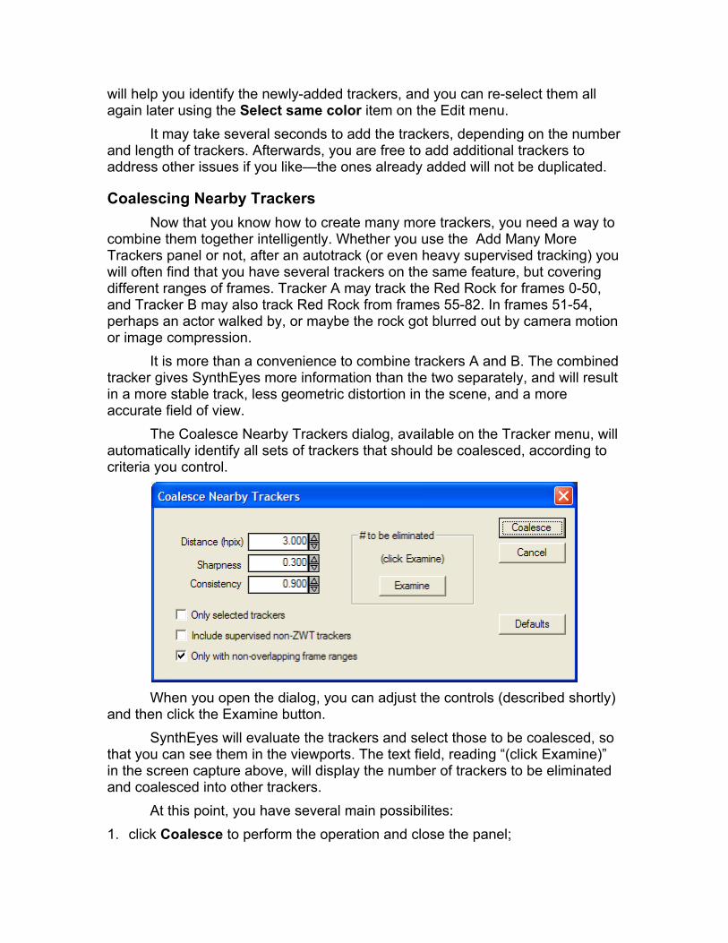
will help you identify the newly-added trackers, and you can re-select them all again later using the Select same color item on the Edit menu.
It may take several seconds to add the trackers, depending on the number and length of trackers. Afterwards, you are free to add additional trackers to address other issues if you like—the ones already added will not be duplicated.
Coalescing Nearby Trackers Now that you know how to create many more trackers, you need a way to
combine them together intelligently. Whether you use the Add Many More Trackers panel or not, after an autotrack (or even heavy supervised tracking) you will often find that you have several trackers on the same feature, but covering different ranges of frames. Tracker A may track the Red Rock for frames 0-50, and Tracker B may also track Red Rock from frames 55-82. In frames 51-54, perhaps an actor walked by, or maybe the rock got blurred out by camera motion or image compression.
It is more than a convenience to combine trackers A and B. The combined tracker gives SynthEyes more information than the two separately, and will result in a more stable track, less geometric distortion in the scene, and a more accurate field of view.
The Coalesce Nearby Trackers dialog, available on the Tracker menu, will automatically identify all sets of trackers that should be coalesced, according to criteria you control.
When you open the dialog, you can adjust the controls (described shortly)
and then click the Examine button. SynthEyes will evaluate the trackers and select those to be coalesced, so
that you can see them in the viewports. The text field, reading “(click Examine)” in the screen capture above, will display the number of trackers to be eliminated and coalesced into other trackers.
At this point, you have several main possibilites: 1. click Coalesce to perform the operation and close the panel;

2. adjust the controls further, and Examine again; 3. close the dialog box with the close box (X) at top right (circle at top left on
Mac), then examine the to-be-coalesced trackers in more detail in the viewports; or
4. Cancel the dialog, restoring the previous tracker selection set. If you are unsure of the best control settings to use, option 3 will let you
examine the trackers to be coalesced carefully, zooming into the viewports. You can then open the Coalesce Nearby Trackers dialog again, and either adjust the parameters further, or simply click Coalesce if the settings are satisfactory.
What Does Nearby Mean? The Distance, Sharpness, and Consistency controls all factor into the
decision whether two trackers are close enough to coalesce. It is a fairly complex decision, taking into account both 2-D and 3-D locations, and is not particularly amenable to human second-guessing. The controls are pretty straightforward, though.
As an aside, it might seem that all that is needed is to measure the 3-D distance between the computed tracker points, and coalesce them if the points are within a certain distance measured in 3-D (not in pixels). However, this simplistic approach would perform remarkable poorly, because the depth uncertainty of a tracker is often much larger than the uncertainty in its horizontal image-plane position. If the distance was large enough to coalesce the desired trackers, it would be large enough to incorrectly coalesce other trackers.
Instead, SynthEyes uses a more sophisticated and compute-intensive approach which is evaluated over all the active frames of the trackers.
The first and most important parameter is the Distance, measured in horizontal pixels. It is the maximum distance between two trackers that can be considered for coalescing. If they are further apart than this in all frames, they will definitely not be coalesced. If they are closer, some of the time, they may be coalesced, increasingly likely the closer they are.
The second most important parameter, the Consistency, controls how much of the time the trackers must be sufficiently close, compared to their overall lifetime. So very roughly, at 0.7 the trackers must be within the given distance on 70% of the frames. If a track is already geometrically accurate, the consistency can be made higher, but if the solution is marginal, the consistency can be reduced to permit matches even if the two trackers slide past one another.
The third parameter, Sharpness, controls the extent to which the exact distance between trackers affects the result, versus the fact that they are within the required Distance at all. If Sharpness is zero, the exact distance will not matter at all, while at a sharpness of one (the maximum), if the trackers are at almost the maximum distance, they might as well be past it.
Sharpness can be used to trade off some computer time versus quality of result: a small distance and low sharpness will give a faster but less precise

result. Settings with a larger distance and larger sharpness will take longer to run but product a more carefully-thought-out result—though the two sets of results may be very similar most of the time, because the larger sharpness will make the larger distance nearly equivalent to the smaller distance and low sharpness.
If you are handling a shot with a lot of jitter in the trackers, due to large film or severe compression artifacts, you should decrease the sharpness, because those small differences in distance are in fact meaningless.
What Trackers should be Coalesced? Three checkboxes on the coalesce panel control what types of trackers
are eligible to be coalesced. First, you can request that Only selected trackers be coalesced. This
allows you to lasso-select a region where coalescing is required. (Note: if you only need 2 particular trackers coalesced, for sure, use Combine Trackers instead.)
Second, frequently you will only want to coalesce auto-trackers, or trackers created by the Add Many Trackers dialog. By default, supervised non-zero-weighted trackers are not eligible to be coalesced. This prevents your carefully-constructed supervised trackers from inadvertently being changed. However, you can turn on the Include supervised non-ZWT trackers checkbox to make them eligible.
SynthEyes will also generally coalesce only trackers that are not simultaneously active: for example, it might coalesce two trackers that are valid on frames 0-10 and 15-25, respectively, but not two trackers that are valid on frames 0-10 and 5-15. If both are autotrackers, if they are simultaneously active, they are generally tracking something else. The exception to this is if they are a large autotracker and a small one, or an autotracker and a supervised tracker. To combine overlapping trackers, turn off the Only with non-overlapping frame ranges checkbox.
A satisfactory approach might be to coalesce once with the checkbox on, as is the default, then open the dialog again, turn the checkbox off, and Examine the results to see if something worth coalescing turns up.
An Overall Strategy Although we have talked as if SynthEyes only combines two trackers, in
fact SynthEyes considers all the trackers simultaneously, and can merge three or more trackers together into a single result in one pass.
It is possible that coalescing immediately a second time may produce additional results, but this is probably sufficiently rare to make it unnecessary in routine use.
However, after you coalesce trackers, it will often be helpful to do a Refine solving cycle, then coalesce again. After the first coalesce, the refine cycle will have an improved geometric accuracy due to the longer tracker lifetimes. With the improved geometry, additional trackers may now be stable enough to be

determined to be tracking the same feature, permitting a coalesce operation to combine them together, and the cycle to repeat.
Viewing this pattern in reverse, observe that a broader distance specification will be required initially, when trackers on the same feature may be calculated at different 3-D positions.
This is particularly relevant to green-screen shots, where the comparatively small number of trackable features and their frequently short lifetime, due to occlusion by the actors, can result in higher-than-usual initial geometric inaccuracy.
Because the green-screen tracking marks are generally widely separated, there is little harm in increasing the allowable coalesce Distance. The features can then be coalesced properly, and the Refine cycle will then rectify the geometry. The process can be repeated as necessary.
If you are using Add Many Trackers and then Coalescing and refining, you should turn on the Regular, not ZWT checkbox on the Add Many dialog, so that the added trackers will affect the Refine solution.

Perspective Window The perspective window allows you to go into the scene to view it from
any direction. Or, you can lock the perspective view to the tracked camera view. You can build a collection of test or stand-in objects to evaluate the tracking. Later, we’ll see that it enables you to assemble tracker locations into object models as well.
The perspective window is controlled by a right-click menu, where different mouse modes can be selected. The middle mouse button can always be used for general navigation using the shift and control variations. The left mouse button may be used instead, with the same variations, when the Navigation mode is selected.
Image Overlay The perspective window can be used to overlay inserted objects over the
live imagery, much like the camera view. Select Lock to Current Camera to lock or release, or use the ‘L’ key. Note that when the view is locked to the camera, you can not move or rotate the camera, or adjust the field of view.
Navigation In navigation mode, with the left mouse button, or any time using the
middle mouse button, dragging will pan the display. Control-dragging will cause the camera to look around in different directions, without translating. Control-ALT-dragging will truck the camera forwards or backwards.
ALT-dragging will cause the camera to orbit. The center of the orbit will be the center of any selected vertices in the current edit mesh (more on that later), around a selected object, or around a point in space directly ahead of the camera.
The mouse’s scroll wheel will change the view’s field of view if it is not locked to the camera, or if it is, it will change the current time. If locked, shift-scrolling will zoom the time bar.
If you hold down the Z or ‘/” (apostrophe/double-quote) key when left-clicking, the mouse mode will temporarily change to be navigation mode; the mode will switch back when the mouse button is released. You can also switch to navigate mode using the ‘N’ key. So it is always pretty easy to navigate.
Creating Objects Create objects on the perspective window grid with the Create mesh
object mode. Use the 3-D panel or right-click menu to control what kind of object is created. Selecting an object type from the right-click menu launches the creation mode immediately. If the SynthEyes user interface is set so that a moving object is active on the Shot menu, the created object will be attached to that object.

Moving and Rotating Objects When an object is selected, handles appear. You can either drag the
handle to translate the object along the corresponding axis, or control-drag to rotate around that axis.
The handles appear along the main coordinate system axes by default, so for example, you can always drag an object vertically no matter what its orientation.
However, if you select Local-coordinate handles on the right-click menu, the handles will align with the object’s coordinate system, so that you can translate along a cylinder’s axis, despite its orientation.
Placing Seed Points and Objects In the Place mode, you can slide the selected object around on the
surface of any existing mesh objects. For example, place a pyramid onto the top of a cube to build a small house.
You can also use the place mode to put a tracker’s seed/lock point onto the surface of an imported reference head model, for example, to help set up tracking for marginal shots.
For this latter workflow, set up trackers on the image, import the reference model. Set up a view configuration showing both the Camera view and the Perspective view. Set the perspective view to Place mode. Select each tracker in the camera view, then place its seed point on the reference mesh in the perspective view. You can reposition the reference mesh however you like in the perspective view to make this easy—it does not have to be locked to the source imagery to do this. This work should go quite quickly.
If you need to place trackers (or meshes) at the vertices of the mesh, not on the surface, hold the control key down as you use the place mode, and the position will snap onto the vertices.
Grid Operations The perspective window’s grid is used for object creation and mesh
editing. It can be aligned with any of the walls of the set: floor, back, ceiling, etc. A move-grid mode translates the grid, while maintaining the same orientation, to give you a grid 1 meter above the floor, say.
A shared custom grid position can be matched to the location of several vertices or trackers using the right-click|Grid|To Facets/Verts/Trackers menu item. If 3 trackers(or vertices) are selected, the grid is moved into the plane defined by the three. If two are selected, the grid is rotated to align the side-to-side axis along the two. If one is selected, the grid slides to put that tracker at the origin. So by repeatedly selecting some trackers(vertices) and using this menu command, the grid can be aligned as desired.

You can easily create an object on the plane defined by any 3 trackers by selecting them, aligning the grid to the trackers, then creating the object, which will be on the grid.
You can toggle the display of the grid using the Grid/Show Grid menu item, or the ‘G’ key.
Shadows The perspective window generates shadows to help show tracking quality
and preview how rendered shots will ultimately appear. The 3-D panel includes control boxes for Cast Shadows and Catch
Shadows. Most objects (except for the Plane) will cast shadows by default when they are created.
If there are no shadow-catching objects, shadows will be cast onto the ground plane. This may be more or less useful, depending on your ground plane; if the ground is very irregular or non-existent, this will be confusing.
If there are shadow-catching objects defined, shadows will be cast from shadow-casting objects onto the shadow-catching objects. This can preview complex effects such as a shadow cast onto a rough terrain.
Shadows may be disabled from the main View menu, and the shadow level may be set from the Preferences color settings. The shadow enable status is “sticky” from one run to the next, so that if you do not usually use it, you will not have to turn it off each time you start SynthEyes.
Note that as with most OpenGL fast-shadow algorithms, there can be shadow artifacts in some cases. Final shadowing should be generated in your 3-D rendering application.
Note that the camera viewport does not display shadows by design.
Edit Mesh The perspective window allows meshes to be constructed and edited,
which is discussed in Building Meshes from Tracker Positions. One mesh can be selected as an edit mesh at any time―select a mesh, then right-click Set Edit Mesh or hit the ‘M’ key.
Preview Movie After you solve and add a few test objects, you can render a test
Quicktime movie (or a BMP, OpenEXR, PNG (PC only), SGI, or Targa sequence). While the RAM-based playback is limited by the amount of RAM, and has a simplified drawing scheme to save time, the preview movie supports antialiasing. It can run at the full rate regardless of length.
Right-click in the perspective window to bring up the menu and select the Preview Movie item to bring up a dialog allowing the output file name, compression settings, and various display control settings to be set. Usually you

will want to select square pixel output for playback on computer monitors in Quicktime; it will convert 720x480 source to 640x480, for example, so the preview will not be stretched horizontally.
Technical Controls The Scene Settings dialog contains many numeric settings for the
perspective view, such as near and far camera planes, tracker and camera icon sizes, etc. You can access the dialog either from the main Edit menu, or from the perspective window’s right-click menu.
By default, this items are sized proportionate to the current “world size” on the solver control panel. Before you go nuts changing the perspective window settings, consider whether it really means that you need to adjust your world size instead!
Exporting to Your Animation Package Once you are happy with the object paths and tracker positions, use the
Export menu items to save your scene. The following options are currently available (note that this list is
constantly being expanded; check the web site):
• 3ds max 4 or later (Maxscript). Should be usable for 3D Studio MAX 3 as well. Separate versions for 3dsmax 5 and earlier, and 3dsmax 6 and later.
• After Effects (via a special maya file) • Bentley Microstation • Blender • Carrara • Cinema 4D (via Lightwave scene) • Combustion • ElectricImage (less integrated due to EI import limitations) • FLAIR motion control cameras (Mark Roberts Motion Control) • Flame (3-D) • Fusion 5 • Hash Animation:Master. Hash 2001 or later. • Houdini • Inferno 3-D Scene. • Lightwave LWS. Use for Lightwave, Cinema 4D • Maya scene file • Mistika • Motion – 2-D • Nuke (D2 Software, subsidiary of Digital Domain) • Particle Illusion • Poser • Realsoft 3D • Shake (several 2-D/2.5-D plus Maya for 3-D scenes) • SoftImage XSI, via a dotXSI file • Toxik • trueSpace • Vue 5 and 6 Infinite • VIZ (via 3ds Max scene)
SynthEyes offers a scripting language, SIZZLE™, that makes it easy to modify the exported files, or even add your own export type. See the separate SIZZLE User Manual for more information. New export types are being added all the time, check the export list in SynthEyes and the support site for the latest packages or beta versions of forthcoming exporters.

General Procedures You should already have saved the scene as a SynthEyes file before
exporting. Select the appropriate export from the list in the File/Exports area. SynthEyes keeps a list of the last 3 exporters used on the top level of the File menu as well.
There is also an export-again option, that repeats the last export performed by this particular scene file, with the most-recently-used export options, without bring up the export-options dialog again to save time for repeated exports.
When you export, SynthEyes uses the file name, with the appropriate file extension, as the initial file name. By default, the exported file will be placed in a default export folder (as set using the preferences dialog).
In most cases, you can either open the exported file directly, or if it is a script, run the script from your animation package. For your convenience, SynthEyes puts the exported file name onto the clipboard, where you can paste it (via control-V or command-V) into the open-file dialog of your application, if you want. (You can disable this from the preferences panel if you want.)
Note that the detailed capabilities of each exporter can vary somewhat. Some scripts offer popup export-control dialogs when they start, or small internal settings at the beginning of each Sizzle script. For example, 3ds max does not offer a way to set the units from a script before version 6 and the render settings are different, so there slightly different versions for 3dsmax 5 and 6+. Settings in the Maya script control the re-mapping of the file name to make it more suitable for Maya on Linux machines. If you edit the scripts, using a text editor such as Windows’ Notepad, you may want to write down any changes as they must be re-applied to subsequent upgraded versions.
The Coordinate System control panel offers an Exportable checkbox that can be set for each tracker. By default, all trackers will be exported, but in some cases, especially for compositors, it may be more convenient to export only a few of the trackers. In this case, select the trackers you wish to export, hit control-I to invert the selection, then turn off the checkbox. Note that particular export scripts can choose to ignore this checkbox.
Setting the Units of an Export SynthEyes uses generic units: a value of 10 might mean 10 feet, 10
meters, 10 miles, 10 parsecs—whatever you want. It does not matter to SynthEyes. This works because match-moving never depends on the overall scale of the scene.
SynthEyes generally tries to export the same way as well—sending its numbers directly as-is to the selected animation or compositing package.
However, some software packages use an absolute measurement system where, for instance, Lightwave requires that coordinates in a scene file always be

in meters. If you want something else inside Lightwave, it will automatically convert the values.
For such software, SynthEyes needs to know what units you consider yourself to be using within SynthEyes. It doesn’t care, but it needs to tell the downstream package the right thing, or pre-scale the values to match your intention.
To set the SynthEyes units selection, use the Units setting on the SynthEyes preferences panel. Changing this setting will not change any numbers within SynthEyes; it will only affect certain exports.
The exports affected by the units setting are currently these:
• After Effects (3-D)
• Hash Animation Master
• Lightwave
• 3ds max
• Maya
• Poser Before exporting to one of these packages, you should verify your units
setting. Alternatively, if you observe that your imported scene has different values than in SynthEyes, you should check the units setting in SynthEyes.
Generic 2-D Tracker Exporters There are a number of similar exporters that all output 2-D tracker paths to
various compositing packages. Why 2-D, you protest? For starters, SynthEyes tracking capabilities can be faster and more accurate. But even more interestingly, you can use the 2-D export scripts to achieve some effects you could not with the compositing package alone.
For image stabilizing applications, the 2-D export scripts will average together all the selected trackers within SynthEyes, to produce a synthetic very stable tracker.
For corner-pinning applications, you can have SynthEyes output not the 2-D tracker location, but the re-projected location of the solved 3-D point. This location can not only be smoother, but continues to be valid even if the tracker goes off-screen. So suppose you need to insert a painting into an ornate picture-frame using corner pinning, but one corner goes off-screen during part of the shot. By outputting the re-projected 3-D point (Use solved 3-D points checkbox), the corner pin can be applied over the entire shot without having to guess any of the path.
Taking this idea one step further, you can create an “extra” point in 3-D in SynthEyes. Its re-projected 2-D position will be averaged with any selected

trackers; if there are none, its position will be output directly. So you can do a four-corner pin even if one of the corners is completely blocked or off-screen.
By repeating this process several times, you can create any number of synthetic trackers, doing a four-corner insert anywhere in the image, even where there are no trackable features. Of course, you could do this with using a 3-D compositing environment, but that might not be simplest.
At present, there are compatible 2-D exporters for AfterEffects, Digital Fusion, Discreet (Combustion/Inferno/Flame), Particle Illusion, and Shake. Note that you will need to import the tracker data file (produced by the correct SynthEyes exporter) into a particular existing tracker in your compositing package.
There is also a 2-D exporter that exports all tracker paths into a single file, with a variety of options to change frame numbers and u/v coordinates. A similar importer can read the same file format back in. Consequently, you can use the pair to achieve a variety of effects within SynthEyes, including transferring trackers from SynthEyes file to SynthEyes file, as described in the section on Merging Files and Tracks. This format can also be imported by Fusion.
Generic 3-D Exporters There are several 3-D exports that produce plain text files. You can use
them for any software SynthEyes don’t already support, for example, non-visual-effects software. You can also use them as a way to manipulate data with little shell, AWK, or Perl scripts, for example.
Importantly, you can also use them as a way to transfer data between SynthEyes scene files, for example, to compute some tracker locations to be used by a number of shots. There are several ways to do this, see the section on Merging Files and Tracks.
The generic exports are Camera/Object Path for a path, Plain Trackers for the 3-D coordinates of trackers and helper points, and corresponding importers. You can import 3-D locations to create either helper points, or trackers. This latter option is useful to bring in surveyed coordinates for tracking.
After Effects 3-D Procedure 1. Export to After Effects in SynthEyes to produce a (special) .ma file. 2. In After Effects, do a File/Import File 3. Change "Files of Type" to All File Formats 4. Select the .ma file 5. Double-click the Square-whatever composition 6. Re-import the original footage 7. Click File/Interpret Footage/Main and be sure to check the frame rate and
pixel aspect. 8. Rewind to the beginning of the shot 9. Drag the reimported footage from the project window into the timeline as
the first layer

10. Tracker nulls have a corner at the active point, instead of being centered on the active point as in SynthEyes.
After Effects 2-D Procedure 1. Select one or more trackers to be exported. 2. Export using the After Effects 2-D Clipboard. You can select either the 2-D
tracking data, or the 3-D position of tracker re-projected to 2-D. 3. Open the text file produced by the export 4. In the text editor, select all the text, using control-A or command-A. 5. Copy the text to the clipboard with control-C or command-C. 6. In After Effects, select a null to receive the path. 7. Paste the path into it with control-V or command-V.
Bentley MicroStation You can exporter to Bentley’s Microstation V8 XM Edition by following
these directions. Exporting from SynthEyes
1. MicroStation requires that animated backgrounds consist of a consecutive sequence of numbered images, such as JPEG or Targa images. If necessary, the Preview Movie capability in SynthEyes’s Perspective window can be used to convert AVIs or MOVs to image sequences.
2. Perform tracking, solving, and coordinate system alignment in SynthEyes. (Exporting coordinates from MicroStation into SynthEyes may be helpful)
3. File/Export/Bentley MicroStation to produce a MicroStation Animation (.MSA) file. Save the file where it can be conveniently accessed from MicroStation. The export parameters are listed below. SynthEyes/MicroStation Export Parameters: Target view number. The view number inside MicroStation to be
animated by this MSA file (usually 2) Scaling. This is from MicroStation’s Settings/DGN File Settings/Working
Units, in the Advanced subsection: the resolution. By default, it is listed as 10000 per distance meter, but if you have changed it for your DGN file, you must have the same value here.
Relative near-clip. Controls the MicroStation near clipping-plane distance. It is a “relative” value, because it is multiplied by the SynthEyes world size setting. Objects closer than this to the camera will not be displayed in MicroStation.
Relative view-size. Another option to adjust as needed if everything is disappearing from view in MicroStation.
Relative far-clip. Controls the MicroStation far clipping-plane distance. It is a “relative” value, because it is multiplied by the SynthEyes world size setting. Objects farther than this from the camera will not be displayed in MicroStation.

Importing into MicroStation 1. Open your existing 3-D DGN file. Or, create a new one, typically based on
seed3d.dgn 2. Open the MicroStation Animation Producer from
Utilities/Render/Animation 3. File/Import .MSA the .msa file written by the SynthEyes exporter. 4. Set the View Size correctly—this is required to get a correct camera
match. a. Settings/Rendering/View Size b. Select the correct view # (typically 2) c. Turn off Proportional Resize d. Set X and Y sizes as follows. Multiply the height(Y) of your image,
in pixels, by the aspect ratio (usually 4:3 for standard video or 16:9 for HD) to get the width(X) value. For example, if your source images are 720x480 with a 4:3 aspect ratio, the width is 480*4/3 = 640, so set the image size to X=640 and Y=480, either directly on the panel or using the “Standard” drop-down menu. This process prevents horizontal (aspect-ratio) distortion in your image.
e. Hit Apply f. Turn Proportional Resize back on g. Close the view size tool
5. On the View Attributes panel, turn on the Background checkbox. 6. Bring up the Animation toolbar (Tools/Visualization/Animation) and select
the Animation Preview tool. You can dock it at the bottom of MicroStation if you like.
7. If you scrub the current time on the Animation Preview, you’ll move through your shot imagery, with synchronized camera motion. Unless you have some 3-D objects in the scene, you won’t really be able to see the camera motion, however.
8. If desired, use the Tools/3-D Main/3-D Primitives toolbar to create some test objects (as you probably did in SynthEyes).
9. To see the camera cone of the camera imported from SynthEyes, bring up Tools/Visualization/Rendering, and select the Define Camera tool. Select the view with the SynthEyes camera track as the active view in the Define Camera tool, and turn on the Display View Cone checkbox. Transferring 3-D Coordinates If you would like to use within MicroStation the 3-D positions of the
trackers, as computed by SynthEyes, you can bring them into MicroStation as follows.
1. You have the option of exporting only a subset of points from SynthEyes to MicroStation. All trackers are exported by default; turn off the Exportable checkbox on the coordinate system panel for those you don’t wish to export. You may find it convenient to select the ones you want, then Edit/Invert Selection, then turn off the box.
2. In SynthEyes, File/Export/Plain Trackers with Set Names=none, Scale=1, Coordinate System=Z Up. This export produces a .txt file listing all the XYZ tracker coordinates.
3. In MicroStation, bring up the Tools/Annotation/XYZ Text toolbar. 4. Click the Import Coordinates tool. Select the .txt file exported from
SynthEyes in Step 1. Set Import=Point Element, Order=X Y Z, View=2 (or whichever you are using). Transferring Meshes SynthEyes uses two types of meshes to help align and check camera
matches: mesh primitives, such as spheres, cubes, etc; and tracker meshes, built from the computed 3-D tracker locations. The tracker meshes can be used to model irregular areas, such as a contoured job site into which a model will be inserted. Both types of models can be transferred as follows:
1. In SynthEyes, select the mesh to be exported, by clicking on it or selecting it from the list on the 3-D panel.
2. Select the File/Export/STL Stereolithography export, and save the mesh to a file.
3. In MicroStation, select File/Import STL and select the file written in step 2. You can use the default settings.
4. Meshes will be placed in MicroStation at the same location as in SynthEyes.
5. You can bring up its Element/Information and assign it a material. To Record the Animation
1. Select the Record tool on the Animation toolbar (Tools/Visualization/Animation)
2. Important: Be sure the correct (square pixels) output image size is selected, the same one as the viewport size. For example, if your input is 4:3 720x480 DV footage, you MUST select 640x480 output to achieve 4:3 with square pixels (ie 640/480 = 4/3). MicroStation always outputs square pixels. You can output images with any overall aspect you wish, as long as the pixels are square (pixel aspect ratio is 1.0). Note that HD images already have square pixels.
3. Don’t clobber your input images! Be sure to select a different location for your output footage than your input.
Blender Directions: 1. In SynthEyes, export to Blender(Python) 2. Remember or write down the AspX value displayed (89 for this example) 3. Start Blender 4. Delete the default cube and light 5. Open the blender Text Editor 6. Open the Script 7. If the shot has a zoom lens:
a. Select the camera

b. Switch to the IPO panel c. Select the Camera Ipo d. Select the Lens channel e. Left click to create a key (and thus an IPO curve) f. Curve/Snap to Frame g. Switch back to the text editor
8. Hit ALT-P to run the script 9. Select the camera (usually Camera01) in the 3-D Viewport 10. In the 3-D view, hit View/Camera to look through the camera 11. Hit View/Background image 12. Click Use Background Image 13. Click Texture 14. Click the up/down arrow, select Camera01Tex or equivalent 15. Go to the Buttons panel 16. Select the Scene Settings (F10) 17. Set AspX to the pixel aspect ratio displayed earlier
Cinema 4D Procedure 1. Export from SynthEyes in Lightwave Scene format (.lws) — see below. 2. Start C4D, open the .lws file 3. From the Objects menu, add a Background 4. Create a new Texture with File/New down below. 5. At right, click on “…” next to the file name for texture. 6. Select your source file. 7. Click on the right-facing triangle button next to the file name, select Edit. 8. Select the Animation panel 9. Click the Calculate button at the bottom. 10. Drag the new texture from the texture editor onto the “Background” on the
object list. Background now appears in the viewport.
DotXSI Procedure 1. In SynthEyes, after completing tracking, do File/Export/dotXSI to create a
.xsi file somewhere. 2. Start Softimage, or do a File/New. 3. File/Import/dotXSI... of the new .xsi file from SynthEyes. The options may
vary with the XSI version, but you want to import everything. 4. Set the camera to Scene1.Camera01 (or whatever you called it in
SynthEyes). 5. Open the camera properties. 6. In the camera rotoscopy section, select New from Source and then the
source shot. 7. Make sure “Set Pixel Ratio to 1.0” is on. 8. Set “Use…” pixel ratio to “Camera Pixel Ratio” (should be the default) 9. In the Camera section, make sure that Field of View is set to Horizontal. 10. Make sure that the Pixel Aspect Ratio is correct. In SynthEyes, select
Shot/Edit Shot to see the pixel aspect ratio. Make sure that XSI has the

exact same value: 0.9 is not a substitute for 0.889, so fix it! Back story: XSI does not have a setting for 720x480 DV, and 720x486 D1 causes errors!
11. Close the camera properties page. 12. On the display mode control (Wireframe, etc), turn on Rotoscope.
ElectricImage The ElectricImage importer relies on a somewhat higher level of user
activity than normal, in the absence of a scripting language for EI. You can export either a camera or object path, and its associated trackers.
1. After you have completed tracking in SynthEyes, select the camera/object you wish to export from the Shots menu, then select File/Export/Electric Image. SynthEyes will produce two files, an .obm file containing the trajectory, and an .obj file containing geometry marking the trackers.
2. In ElectricImage, make sure you have a camera/object that matches the name used in SynthEyes. Create new cameras/objects as required. If you have Camera01 in SynthEyes, your camera should be "Camera 1" in EI. The zero is removed automatically by the SynthEyes exporter.
3. Go to the Animation pull-down menu and select the "Import Motion" option.
4. In the open dialog box, select "All Files" from the Enable pop-up menu, so that the .obm file will be visible.
5. Navigate to, and select, the .obm file produced by SynthEyes. This will bring up the ElectricImage motion import dialog box which allows you to override values for position, rotation, etc. Normally, you will ignore all these options as it is simpler to parent the camera/object to an effector later. The only value you might want to change is the "start time" to offset when the camera move begins. Click OK and you will get a warning dialog about the frame range. This is a benign warning that sets the "range of frames" rendering option to match the length of the incoming camera data. Hitting cancel will abort the operation, so hit OK and the motion data will be applied to the camera.
6. Select "Import Object" from the Object pull-down menu. 7. Enable "All Files" in the pop-up menu. 8. Select the .obj file produced by SynthEyes. 9. Create a hierarchy by selecting one tracker as the parent, or bringing in all
trackers as separate objects. 10. If you are exporting an object path, parent the tracker object to the object
holding the path.
Fusion 5 There are several Fusion-compatible exporters. The main exporter is the
Fusion 5 composition export, which can be opened directly in Fusion.

The Tracker 2-D Paths export can write all the exportable trackers to a text file, which can then be read in Fusion with the Import SynthEyes Trackers script and assigned to any Point-type input on a node. Select a node and start the Import script from its right-click menu. At present, it appears that you should animate the desired control before importing, then tell the script to proceed anyway when it notices that the control is already animated.
There is also a generic 2-D path exporter for Fusion.
Houdini Instructions: 1. File/New unless you are addding to your existing scene. 2. Open the script Textport 3. Type source "c:/shots/scenes/flyover.cmd" or equivalent. 4. Change back from COPs to OBJs.
Lightwave The Lightwave exporter produces a lightwave scene file (.lws) with several
options, one of them crucial to maintaining proper synchronization. As mentioned earlier, Lightwave requires a units setting when exporting
from SynthEyes. The SynthEyes numbers are unitless: by changing the units setting in the lightwave exporter as you export, you can make that 24 in SynthEyes mean 24 inches, 24 feet, 24 meters, etc. This is different than in Lightwave, where changing the units from 24 inches would yield 2 feet, 0.61 meters, etc. This is the main setting that you may want to change from scene to scene.
Lightwave has an obscure preferences-like setting on its Compositing panel (on the Windows menu) named “Synchronize Image to Frame.” The available options are zero or one. Selecting one shifts the imagery one frame later in time, and this is the Lightwave default. However, for SynthEyes, a setting of zero will generally be more useful (unless the SynthEyes preference First Frame is 1 is turned on). The Lightwave exporter from SynthEyes allows you to select either 0 or 1. We recommend selecting zero, and adjusting Lightwave to match. You will only have to do this once, Lightwave remembers it subsequently. In all cases, you must have a matching value on the exporter UI and in Lightwave, or you will cause a subtle velocity-dependent error in your camera matches in Lightwave that will drive you nuts until you fix the setting.
The exporter also has a checkbox for using DirectShow. This checkbox applies only for AVIs, and should be on for most AVIs that contain advanced codecs such as DV or HD. If an AVI uses an older codec and is not opened automatically within Lightwave, export again with this checkbox turned off.
Nuke The nuke exporter produces a nuke file you can open directly. The pop-up
parameter panel lets you indicate if you have a slate frame at the start of the shot, or select renderable or non-rendering tracker marks. The renderable marks

are better for tracking, the non-rendering marks better for adding objects within Nuke’s 3-D view.
Poser Poser struggles a little to be able to handle a match-moved camera, so the
process is a bit involved. Hopefully Curious Labs will improve the situation in further releases.
The shot must have square pixels to be used properly by Poser; it doesn't understand pixel aspect ratios. So if you have a 720x480 DV source, say, you need to resample it in SynthEyes, AfterEffects or something to 640x480. Also, the shot has to have a frame rate of exactly 30 fps. This is a drag since normal video is 29.97 fps, and Poser thinks it is 29.00 fps, and trouble ensues. One way to get the frame rate conversion without actually mucking up any of the frames is to store the shot out as a frame sequence, then read it back in to your favorite tool as a 30 fps sequence. Then you can save the 640x480 or other square-pixel size.
Note that you can start with a nice 720x480 29.97 DV shot, track it in SynthEyes, convert it as above for Poser, do your poser animation, render a sequence out of Poser, then composite it back into the original 720x480.
One other thing you need to establish at this time---exactly how many frames there are in your shot. If the shot ranges are 0 to 100, there are 101; from 10 to 223, there are 214.
1. After completing tracking in SynthEyes, export using the Poser Python exporter.
2. Start Poser. 3. Set the number of frames of animation, at bottom center of the Poser
interface, to the correct number of frames. It is essential that you do this now, before reading the python script
4. File/Run Python Script on the python script output from SynthEyes. 5. The Poser Dolly camera will be selected and have the SynthEyes camera
animation on it. There are little objects for each tracker, and also SynthEyes boxes, cones, etc are brought over into Poser. Open Question: How to render out of Poser with the animated movie
background. The best approach appears to be to render against black with an alpha channel, then composite over the original shot externally.
Shake SynthEyes offers three specific exporters for Shake, plus one generic one:
1. MatchMove Node. 2. Tracker Node 3. Tracking File format 4. 3-D Export via the “AfterFX via .ma” or Maya ASCII exports.
The first two formats (Sizzle export scripts) produce shake scripts (.shk files); the third format is a text file. The fourth option produces Maya scene files that Shake reads and builds into a scene using its 3-D camera.
We’ll start with the simplest, the tracking file format. Select one tracker and export with the Shake Tracking File Format, and you will have a track that can be loaded into a Shake tracker using the load option. You can use this to bring a track from SynthEyes into existing Shake tracking setups.
Building on this basis, #2, Tracker Node, exports one or more selected trackers from SynthEyes to create a single Tracker Node within Shake. There are some fine points to this. First, you will be asked whether you want to export the solved 3-D positions, or the tracked 2-D positions. These values are similar, but not the same. If you have a 3-D solution in SynthEyes, you can select the solved 3-D positions, and the export will be the “ideal” tracked (predicted) coordinates, with less jitter than the plain 2-D coordinates.
Also, since you might be exporting from a PC to a Mac or Linux machine, the image source file(s) may be named differently: perhaps X:\shots1\shot1_#.tga on the PC, and //macmachine/Users/tom/shots/shot1_#.tga on the PC. The Shake export script’s dialog box has two fields, PC Drive and Mac Drive, that you can set to automatically translate the PC file name into the Mac file name, so that the Shake script will work immediately. In this example, you would set PC Drive to “X:\\” and Mac Drive to “//macmachine/Users/tom/”.
Finally, the MatchMove node exporter looks not for trackers to export, but for SynthEyes planes! Each plane (created from the 3-D panel) is exported to Shake by creating four artificial trackers (in Shake) at the corners of the plane. The matchmove export lets you insert a layer at any arbitrary position within the 3-D environment calculated by SynthEyes. For example, you can insert a matte painting into a scene at a location where there is nothing to track. You can use a collection of planes, positioned in SynthEyes, to obtain much of the effect of a 3-D camera. The matchmove node export also provides PC to Mac/Linux file name translation.
trueSpace Directions: Warning: trueSpace has sometimes had problems executing the exported
script correctly. Hopefully Caligari will fix this soon.
1. In SynthEyes, export to trueSpace Python. 2. Open trueSpace. 3. Right-click the Play button in the trueSpace animation controls. 4. Set the correct BaseRate/PlayRate in the animation parameters to match
your source shot. 5. Open the Script Editor. 6. From inside the Script Editor, Open/Assign the python script you created
within SynthEyes.
7. Click Play (Time On) in the Script Manager. 8. When the Play button turns off, close the ScriptManager. 9. Open the Object Info panel. 10. Verify that the SynthEyes camera is selected (usually Camera01). 11. Change the Perspective view to be View from Object. 12. Select the Camera01Screen. 13. Open the Material Editor (paint pallete). 14. Right click on Color shaders button. 15. Click on (Caligari) texture map, sending it to the Material Editor color
shader. 16. Open the subchannels of the Material Editor (Color, Bump, Reflectance). 17. On the Color channel of the Material Editor, right click on the "Get Texture
Map" button and select your source shot. 18. Check the Anim box. 19. Click the Paint Object button on the Material Editor. 20. Click on File/Display Options and change the texture resolution to
512x512. 21. You may want to set up a render background to overlay animated objects
on the background, or you can use an external compositing program. Make the Camera01Screen object invisible before rendering.
22. In trueSpace, you need to pay special attention to get the video playback synchronized with rest of the animation, and to get the render aspect ratio to match the original. For example, you must add the texture map while you are at frame zero, and you should set the pixel aspect ratio to match the original (SynthEyes's shot panel will tell you what it is).
Vue 5 Infinite The export to Vue Infinite requires a fair number of manual steps pending
further Vue enhancements. But with a little practice, they should only take a minute or two.
1. Export from SynthEyes using the Vue 5 Infinite setting. The options can be left at their default settings unless desired. You can save the python script produced into any convenient location.
2. Start Vue Infinite or do a File/New in it. 3. Select the Main Camera 4. On its properties, turn OFF "Always keep level" 5. Go to the animation menu, turn ON the auto-keyframe option. 6. Select the Python/Run python script menu item, select the script
exported from SynthEyes, and run it. 7. In the main camera view, select the "Camera01 Screen" object (or
the equivalent if the SynthEyes camera was renamed) 8. In the material preview, right-click, select Edit Material.

9. The material editor appears, select Advanced Material Editor if not already.
10. Change the material name to flyover or whatever the image shot name is.
11. Select the Colors tab. 12. Select "Mapped picture" 13. Click the left-arrow "Load" icon under the black bitmap preview
area 14. In the "Please select a picture to load" dialog, click the Browse File
icon at the bottom --- a left arrow superimposed on a folder 15. Select your image file in the Open Files dialog. If it is an image
sequence, select the first image, then shift-select the last. 16. On the material editor, under the bitmap preview area, click the
clap-board animation icon to bring up the Animated Texture Options dialog
17. Set the frame rate to the correct value. 18. Turn on "Mirror Y" 19. Hit OK on the Animated Texture dialog 20. On the drop-down at top right of the Advanced Material Editor,
select a Mapping of Object- Parametric 21. Turn off "Cast shadows" and "Receive shadows" 22. Back down below, click the Highlights tab 23. Turn Highlight global intensity down to zero. 24. Click on the Effects tab 25. Turn Diffuse down to zero 26. Click the Ambient data-entry field and enter 400 27. Hit OK to close the Advanced Material Editor 28. Select the Animation/Display Timeline menu item (or hit F11) 29. If this is the first time you have imported from SynthEyes to Vue
Infinite, you must perform the following steps: a. Select File/Options menu item. b. Click the Display Options tab c. Turn off "Clip objects under first horizontal plane in main
view only", otherwise you will not be able to see the background image.
d. Turn off "Clip objects under first horizontal plane (ground / water)
e. Turn off "Stop camera going below clipping plane (ground / water)" if needed by your camera motion.
f. Hit OK 30. Delete the "Ground" object 31. If you are importing lights from SynthEyes, you can delete the Sun
Light as well, otherwise, spin the Sun Light around to point at the camera screen, so that the image can be seen in the preview window.
32. You may have to move the time bar before the image appears. Vue Infinite only shows the first image of the sequence, so you can verify alignment at frame zero.
33. You will later want to disable the rendering of the trackers, or delete them outright.
34. Depending on what you are doing, you may ultimately wish to delete or disable the camera screen as well, for example, if you will composite an actor in front of your Vue Infinite landscape.
35. The import is complete; you can start working in Vue Infinite. You should make probably save a copy of the main camera settings so that you can have a scratch camera available as you prepare the scene in Vue Infinite.
Vue 6 Infinite 1. Export from SynthEyes using the Vue 6 Infinite option, producing a
maxscript file. 2. Import the maxscript file in Vue 6 Infinite 3. Adjust the aspect ratio of the backdrop to the correct overall aspect ratio
for your shot. This is important since Vue assumes square pixels, and if they aren’t (for all DV, say), the camera match will be off badly.
Troubleshooting Sliding. This is what you see when an object appears to be moving,
instead of stationary on a floor, for example, due to placement errors. Almost always, this is because the inserted object has not been located in exactly the right spot, rather than indicating a tracking problem. Often, an object is inserted an inch or two above a floor. Be sure you have tracked the right spot: to determine floor level, track marks on the floor, not tennis balls sitting on it, which are effectively an inch or two higher. If you have to work from the tennis balls, set up the floor coordinate system taking the ball radius into account, or place the object the corresponding amount below the apparent floor.
Also, place trackers near the location of the inserted object whenever possible.
Another common cause of sliding: a tracker that jumps from one spot to another at some frame during the track.
“It lines up in SynthEyes, but not XXX.” The export scripts do what they can to try to ensure that everything lines up just as nicely in your post-tracking application as in SynthEyes, but life is never simple. There are preferences that may be different, maybe you’re integrating into an existing setup, maybe you didn’t think hitting xxx would matter, etc. The main causes of this problem have been when the field of view is mangled (especially when people worry about focal length instead, and have the wrong back plate width), and when the post-tracking application turns out to be using a slightly different version of the images, perhaps one frame earlier or later, or with or without some cropping.
“Can’t locate satisfactory initial frame” when solving. When the Constrain checkbox is on (Solver panel), the constrained trackers need to be active on the begin and end frames. Consequently, keeping Constrain off is preferable. Alternatively, the shot may lack very much parallax. Try setting the Solver Panel’s Begin and/or End frames manually. For example, set the range to the entire shot, or a long run of frames with many trackers in common. However, keep the range short enough that the camera motion from beginning to end stays around 30 degrees maximum rotation about any axis.
“I tried Tripod mode, and now nothing works” and you get Can’t locate satisfactory initial frame or another error message. Tripod mode turns all the trackers to Far, since they will have no distance data in tripod mode. Select all the trackers, and turn Far back off (from the coordinate system control panel).
Bad Solution, very small field of view. Sometimes the final solution will be very small, with a small field of view. Often this means that there is a problem with one or more trackers, such as a tracker that switches from one feature to a different one, which then follows a different trajectory. It might also mean an impossible set of constraints, or sometimes an incomplete set of rotation constraints. You might also consider flipping on the Slow but sure box, or give a hint for a specific camera motion, such as Left or Up. Eliminate inconsistent constraints as a possibility by turning off the Constrain checkbox.

Object Mode Track Looks Good, but Path is Huge. If you’ve got an object mode track that looks good---the tracker points are right on the tracker boxes---but the object path is very large and flying all over the place, usually you haven’t set up the object’s coordinate system, so by default it is the camera position, far from the object itself. Select one tracker to be the object origin, and use two or more additional ones to set up a coordinate system, as if it was a normal camera track.
Master Reset Does Not Work. By design, the master reset does not affect objects or cameras in Refine or Refine Tripod mode: they will have to be set back to their primary mode anyway, and this prevents inadvertent resets.
Can’t open an image file or movie. Image file formats leave room for interpretation, and from time to time a particular program may output an image in a way that SynthEyes is not prepared to read. If you find such a file, please forward it to SynthEyes support. Such problems are generally quick to rectify, once the problematic file can be examined in detail. In the meantime, try a different file format, or different save options, in the originating program, if possible, or use a file format converter if available. Also, make sure you can read the image in a different program, preferably not the one that created it: some images that SynthEyes “couldn’t read” have turned out to be corrupted previously.
Can’t delete a key on a tracker (ie by right-clicking in the tracker view window, or right-clicking the Now button). If the tracker is set to automatically key every 12 frames, and this is one of those keys, deleting it will work, but SynthEyes will immediately add a new key! Usually you want to back up a few frames and add a correct key; then you can delete or correct the original one. Or, increase the auto-key setting. Also, you can not delete a key if the tracker is locked.
Crashes In the event that SynthEyes detects an internal error, it will pop up an
Imminent Crash dialog box asking you if you wish to save a crash file. You should take a screen capture with Print Screen on your keyboard, then respond Yes. SynthEyes will save the current file to a special crash location, then pops up another dialog box that tells you that location (within your Documents and Settings folder).
You should then open a paint program such as Photoshop, Microsoft Paint, Paint Shop Pro, etc, and paste in the screen capture. Save the image to a file, then e-mail the screen capture, the crash save file, and a short description of what you were doing right before the crash, to SynthEyes technical support for diagnosis, so that the problem can be fixed in future releases. If you have Microsoft’s Dr. Watson turned on, forwarding that file would also be helpful.
The crash save file is your SynthEyes scene, right before it began the operation that resulted in the crash. You should often be able to continue using this file, especially if the crash occurred during solving. It is conceivable that the

file might be corrupted, so if you recently had saved the file, you may wish to go back to that file for safety.
Combining Automated and Supervised Tracking It can be helpful to combine automated tracking with some supervised
trackers, especially when you would like to use particular features in the image to define the coordinate system, to help the automated tracker with problematic camera motions, to aid scene modeling, or to stabilize effects insertion at a particular location.
Guide Trackers Guide Trackers are supervised trackers, added before automated
tracking. Pre-existing trackers are automatically used by the automated tracking system to re-register frames as they move. With this guidance, the automated tracking system can accommodate more, or crazier, motions than it would normally expect.
Unless the overall feature motion is very slow, you should always add multiple guide trackers distributed throughout the image, so that at any location in the image, the closest guide tracker has a similar motion. [The main exception: if you have a jittery hand-held shot where, if it was stabilized, the image features actually move rather slowly, you can use only a single guide tracker.]
Note that guide trackers should be much less necessary than in previous versions of SynthEyes, and are processed differently than before.
Supervised Trackers, After Automated Tracking You can easily add supervised trackers after running the automated
tracker. Create the trackers from the Tracker panel, adjust the coordinate system settings as needed, then, on the Solver Panel, switch to Refine mode and hit Go!
Converting Automatic Trackers to Supervised Trackers Suppose you want to take an automatically-generated tracker and modify
it by hand. You may wish to improve it: perhaps to extend it earlier or later in the shot, or to patch up a few frames where it gets off track.
From the Tracking Control Panel, select the automatically-generated tracker(s) you want to work on, and unlock them. This converts them to supervised trackers and sets up a default search region for them.
You can also use the To Golden button on the Feature Control Panel to turn selected trackers from automatic to supervised without unlocking them (and without setting up a search region).
Sometimes, you may wish to convert a number of automatic trackers to supervised, possibly add some additional trackers, and then get rid of all the other automatically-generated trackers, leaving you with a well-controlled group of supervised trackers. The Delete Leaden button will delete all trackers that have not been converted to golden.

You can also use the Combine trackers command to combine a supervised tracker with an automatically-generated one, if they are tracking the same feature.

Stabilization In this section, we’ll go into SynthEyes’ stabilization system in depth, and
describe some of the nifty things that can be done with it. If we wanted, we could have a single button “Stabilize this!” that would quickly and reliably do a bad job almost all the time. If that’s what you’re looking for, there are some other software packages that will be happy to oblige. In SynthEyes, we have provided a rich toolset to get outstanding results in a wide variety of situations.
You might wonder why we’ve buried such a wonderful and significant capability quite so far into the manual. The answer is simple: in the hopes that you’ve actually read some of the manual, because effectively using the stabilizer will require that you know a number of SynthEyes concepts, and how to use the SynthEyes tracking capabilities.
If this is the first section of the manual that you’re reading, great, thanks for reading this, but you’ll probably need to check out some of the other sections too. At the least, you have to read the Stabilization quick-start.
Also, be sure to check the web site for the latest tutorials on stabilization. We apologize in advance for some of the rant content of the following
sections, but it’s really in your best interest!
Why SynthEyes Has a Stabilizer The simple and ordinary need for stabilization arises when you are
presented with a shot that is bouncing all over the place, and you need to clean it up into a solid professional-looking shot. That may be all that is needed, or you might need to track it and add 3-D effects also. Moving-camera shots can be challenging to shoot, so having software stabilization can make life easier.
Or, you may have some film scans which are to be converted to HD or SD TV resolution, and effects added.
People of all skill levels have been using a variety of ad-hoc approaches to address these tasks, sometimes using software designed for this, and sometimes using or abusing compositing software. Sometimes, presumably, this all goes well. But many times it does not: a variety of problem shots have been sent to SynthEyes tech support which are just plain bad. You can look at them and see they have been stabilized, and not in a good way.
We have developed the SynthEyes stabilizer not only to stabilize shots, but to try to ensure that it is done the right way.
How NOT to Stabilize Though it is relatively easy to rig up a node-based compositor to shift
footage back and forth to cancel out a tracked motion, this creates a fundamental problem:

Most imaging software, including you, expects the optic center of an image to fall at the center of that image. Otherwise, it looks weird—the fundamental camera geometry is broken. The optic center might also be called the vanishing point, center of perspective, back focal point, center of lens distortion.
For example, think of shooting some footage out of the front of your car as you drive down a highway. Now cut off the right quarter of all the images and look at the sequence. It will be 4:3 footage, but it’s going to look strange—the optic center is going to be off to the side.
If you combine off-center footage with additional rendered elements, they will have the optic axis at their center, and combined with the different center of the original footage, they will look even worse.
So when you stabilize by translating an image in 2-D (and usually zooming a little), you’ve now got an optic center moving all over the place. Right at the point you’ve stabilized, the image looks fine, but the corners will be flying all over the place. It’s a very strange effect, it looks funny, and you can’t track it right. If you don’t know what it is, you’ll look at it, and think it looks funny but not know what has hit you.
Recommendation: if you are going to be adding effects to a shot, you should ask to be the one to stabilize or pan/scan it also. We’ve given you the tool to do it well, and avoid mishap. That’s always better than having someone else mangle it, and having to explain later why the shot has problems, or why you really need the original un-stabilized source by yesterday.
In-Camera Stabilization Many cameras now feature built-in stabilization, using a variety of
operating principles. These stabilizers, while fine for shooting baby’s first steps, may not be fine at all for visual effects work.
Electronic stabilization uses additional rows and columns of pixels, then shifts the image in 2-D, just like the simple but flawed 2-D compositing approach. These are clearly problematic.
One type of optical stabilizer apparently works by putting the camera imaging CCD chip on a little platform with motors, zipping the camera chip around rapidly so it catches the right photons. As amazing as this is, it is clearly just the 2-D compositing approach.
Another optical stabilizer type adds a small moving lens in the middle of the collection of simple lens comprising the overall zoom lens. Most likely, the result is equivalent to a 2-D shift in the image plane.
A third type uses prismatic elements at the front of the lens. This is more likely to be equivalent to re-aiming the camera, and thus less hazardous to the image geometry.

Doubtless additional types are in use and will appear, and it is difficult to know their exact properties. Some stabilizers seem to have a tendency to intermittently jump when confronted with smooth motions. One mitigating factor for in-camera stabilizers, especially electronic, is that the total amount of offset they can accommodate is small—the less they can correct, the less they can mess up.
Recommendation: It is probably safest to keep camera stabilization off when possible, and keep the shutter time (angle) short to avoid blur, except when the amount of light is limited. Electronic stabilizers have trouble with limited light so that type might have to be off anyway.
3-D Stabilization To stabilize correctly, you need 3-D stabilization that performs “keystone
correction” (like a projector does), re-imaging the source at an angle. In effect, your source image is projected onto a screen, then re-shot by a new camera looking in a somewhat different direction with a smaller field of view. Using a new camera keeps the optic center at the center of the image.
In order to do this correctly, you always have to know the field of view of the original camera. Fortunately, SynthEyes can tell us that.
Stabilization Concepts Point of Interest (POI). The point of interest is the fixed point that is being
stabilized. If you are pegging a shot, the point of interest is the one point on the image that never moves.
POI Deltas (Adjust tab). These values allow you to intentionally move the POI around, either to help reduce the amount of zoom required, or to achieve a particular framing effect. If you create a rotation, the image rotates around the POI.
Stabilization Track. This is roughly the path the POI took—it is a direction in 3-D space, described by pan/tilt/roll angles—basically where the camera (POI) was looking (except that the POI isn’t necessarily at the center of the image).
Reference Track. This is the path in 3-D we want the POI to take. If the shot is pegged, then this track is just a single set of values, repeated for the duration of the shot.
Separate Field of View Track. The image preparation system has its own field of view track. The image prep’s FOV will be larger than main FOV, because the image prep system sees the entire input image, while the main tracking and solving works only on the smaller stabilized sub-window output by image prep. Note that an image prep FOV is needed only for stabilization, not for pixel-level adjustments, downsampling, etc. The Get Solver FOV button transfers the main FOV track to the stabilizer.

Separate Distortion Track. Similarly there is a separate lens distortion track. The image prep’s distortion can be animated, while the main distortion can not. The image prep distortion or the main distortion should always be zero, they should never both be nonzero simultaneously. The Get Solver Distort button transfers the main distortion value (from solving or the Lens-panel alignment lines) to the stabilizer, and begs you to let it clear the main distortion value afterwards.
Stabilization Zoom. The output window can only be a portion of the size of the input image. The more jiggle, the smaller the output portion must be, to be sure that it does not run off the edge of the input (see the Padded mode of the image prep window to see this in action). The zoom factor reflects the ratio of the input and output sizes, and also what is happening to the size of a pixel. At a zoom ratio of 1, the input and output windows and pixels are the same size. At a zoom ratio of 2, the output is half the size of the input, and each incoming pixel has to be stretched to become two pixels in the output, which will look fairly blurry. Accordingly, you want to keep the zoom value down in the 1.1-1.3 region. After an Auto-scale, you can see the required zoom on the Adjust panel.
Re-sampling. There’s nothing that says we have to produce the same size image going out as coming in. The Output tab lets you create a different output format, though you will have to consider what effect it has on image quality. Re-sampling 3K down to HD sounds good; but re-sampling DV up to HD will come out blurry because the original picture detail is not there.
Tracker Paths. One or more trackers are combined to form the stabilization track. The tracker’s 2-D paths follow the original footage. After stabilization, they will not match the new stabilized footage. There is a button, Apply to Trkers, that adjusts the tracker paths to match the new footage, but again, they then match that particular footage and they must be restored to match the original footage (with Remove f/Trkers) before making any later changes to the stabilization. If you mess up, you either have to return to an earlier saved file, or re-track.
Overall Process We’re ready to walk through the stabilization process.
• Track the features required for stabilization: either a full auto-track, supervised tracking of particular features to be stabilized, or a combination.
• If possible, solve the shot either for full 3-D or as a tripod shot, even if it is not truly nodal. The resulting 3-D point locations will make the stabilization more accurate, and it is the best way to get an accurate field of view.
• If you have not solved the shot, manually set the Lens FOV on the Image Preprocessor’s Lens tab (not the main Lens panel) to the best available value. If you do set up the main lens FOV, you can import it to the Lens tab.
• On the Stabilization tab, select a stabilization mode for translation and/or rotation. This will build the stabilization track automatically if there isn’t one
already (as if the Get Tracks button was hit), and import the lens FOV if the shot is solved.
• Adjust the frequency spinner as desired.
• Hit the Auto-Scale button to find the required stabilization zoom
• Check the zoom on the Adjust tab; using the Padded view, make any additional adjustment to the stabilization activity to minimize the required zoom, or achieve desired shot framing.
• Output the shot. If only stabilized footage is required, you are done.
• Update the scene to use the new imagery, and either re-track or update the trackers to account for the stabilization
• Get a final 3-D or tripod solve and export to your animation or compositing package for further effects work.
There are two main kinds of shots and stabilization for them: shots focusing on a subject, which is to remain in the frame, and traveling shots, where the content of the image changes as new features are revealed.
Stabilizing on a Subject Often a shot focuses on a single subject, which we want to stabilize in the
frame, despite the shaky motion of the camera. Example shots of this type include:
• The camera person walking towards a mark on the ground, to be turned into a cliff edge for a reveal.
• A job site to receive a new building, shot from a helicopter orbiting overhead
• A camera car driving by a house, focusing on the house. To stabilize these shots, you will identify or create several trackers in the
vicinity of the subject, and with them selected, select the Peg mode on the Translation list on the Stabilize tab.
This will cause the point of interest to remain stationary in the image for the duration of the shot.
You may also stabilize and peg the image rotation. Almost always, you will want to stabilize rotation. It may or may not be pegged.
You may find it helpful to animate the stabilized position of the point of interest, in order to minimize the zoom required, see below, and also to enliven a shot somewhat.
Some car commercials are shot from a rig that shows both the car and the surrounding countryside as the car drives: they look a bit surreal because the car is completely stationary—having been pegged exactly in place. No real camera rig is that perfect!

Stabilizing a Traveling Shot Other shots do not have a single subject, but continue to show new
imagery. For example,
• A camera car, with the camera facing straight ahead
• A forward-facing camera in a helicopter flying over terrain
• A camera moving around the corner of a house to reveal the backyard behind it
In such shots, there is no single feature to stabilize. Select the Filter mode for the stabilization of translation and maybe rotation. The result is similar to the stabilization done in-camera, though in SynthEyes you can control it and have keystone correction.
When the stabilizer is filtering, the Cut Frequency spinner is active. Any vibratory motion below that frequency (in cycles per second) is preserved, and vibratory motion above that frequency is greatly reduced or eliminated.
You should adjust the spinner based on the type of motion present, and the degree of stabilization required. A camera mounted on a car with a rigid mount, such as a StickyPod, will have only higher-frequency residual vibration, and a larger value can be used. A hand-held shot will often need a frequency around 0.5 Hz to be smooth.
Note: When using filter-mode stabilization, the length of the shot matters. If the shot is too short, it is not possible to accurately control the frequency and distinguish between vibration and the desired motion, especially at the beginning and end of the shot. Using a longer version of the take will allow more control, even if much of the stabilized shot is cut after stabilization.
Minimizing Zoom The more zoom required to stabilize a shot, the less image quality will
result, which is clearly bad. Can we minimize the zoom, and maximize image quality? Of course, and SynthEyes provides the controllability to do so.
Stabilizing a shot has considerable flexibility: the shot can be stable in lots of different ways, with different amounts of zoom required. We want a shot that everyone agrees is stable, but minimizes the effect on quality. Fortunately, we have the benefit of foresight, so we can correct a problem in the middle of a shot, anticipating it long before it occurs, and provide an apparently stable result.
Animating POI The basic technique is to animate the position of the point-of-interest
within the frame. If the shot bumps left suddenly, there are fewer pixels available on the left side of the point of interest to be able to maintain its relative position in the output image, and a higher zoom will be required. If we have already moved the point of interest to the left, fewer pixels are required, and less zoom is required.

Earlier, in the Stabilization Quick Start, we remarked that the 28% zoom factor obtained by animating the rotation could be reduced further. We’ll continue that example here to show how. Re-do the quick start to completion, go to frame 178, with the Adjust tab open, in Padded display mode, with the make key button turned on.
From the display, you can see that the red output-area rectangle is almost near the edge of the image. Grab the purple point-of-interest crosshair, and drag the red rectangle up into the middle of the image. Now everything is a lot safer. If you switch to the stabilize tab and hit Autoscale, the red rectangle enlarges—there is less zoom, as the Adjust tab shows. Only 15% zoom is now required.
By dragging the POI/red rectangle, we reduced zoom. You can see that what we did amounted to moving the POI. Hit Undo twice, and switch to the Final view.
Drag the POI down to the left, until the Delta U/V values are approximately 0.045 and -0.035. Switch back to the Padded view, and you’ll see you’ve done the same thing as before. The advantage of the padded view is that you can more easily see what you are doing, though you can get a similar effect in the Final view by increasing the margin to about 0.25, where you can see the dashed outline of the source image.
If you close the Image Prep dialog and play the shot, you will see the effect of moving the POI: a very stable shot, though the apparent subject changes over time. It can make for a more interesting shot and more creative decisions.
Too Much of a Good Thing? To be most useful, you can scrub through your shot and look for the worst
frame, where the output rectangle has the most missing, and adjust the POI position on that frame.
After you do that, there will be some other frame which is now the worst frame. You can go and adjust that too, if you want. As you do this, the zoom required will get less and less.
There is a downside: as you do this, you are creating more of the shakiness you are trying to get rid of. If you keep going, you could get back to no zoom required, but all the original shakiness, which is of course senseless.
Usually, you will only want to create two or three keys at most, unless the shot is very long. But exactly where you stop is a creative decision based on the allowable shakiness and quality impact.
Auto-Scale Capabilities The auto-scale button can automate the adjustment process for you, as
controlled by the Animate listbox and Maximum auto-zoom settings. With Animate set to Neither, Auto-scale will pick the smallest zoom
required to avoid missing pieces on the output image sequence, up to the

specified maximum value. If that maximum is reached, there will be missing sections.
If you change the Animate setting to Translate, though, Auto-scale will automatically add delta U/V keys, animating the POI position, any time the zoom would have to exceed the maximum.
Rewind to the beginning of the shot, and control-right-click the Delta-U spinner, clearing all the position keys.
Change the Animate setting to Translate, reduce the Maximum auto-zoom to 1.1, then click Auto-Scale. SynthEyes adds several keys to achieve the maximum 10% zoom. If you play back the sequence, you will see the shot shifting around a bit—10% is probably too low given the amount of jitter in the shot to begin with.
The auto-scale button can also animate the zoom track, if enabled with the Animate setting. The result is equivalent to a zooming camera lens, and you must be sure to note that in the main lens panel setting if you will 3-D solve the shot later. This is probably only useful when there is a lot of resolution available to begin with, and the point of interest approaches the boundary of the image at the end of the shot.
Keep in mind that the Auto-scale functionality is relatively simple. By considering the purpose of the shot as well as the nature of any problems in it, you should often be able to do better.
Tweaking the Point of Interest This is different than moving it! When the selected trackers are combined to form the single overall
stabilization track, SynthEyes examines the weight of each tracker, as controlled from the main Tracker panel.
This allows you to shift the position of the point-of-interest (POI) within a group of trackers, which can be handy.
Suppose you want to stabilize at the location of a single tracker, but you want to stabilize the rotation as well. With a single tracker, rotation can not be stabilized. If you select two trackers, you can stabilize the rotation, but without further action, the point of interest will be sitting between the two trackers, not at the location of the one you care about.
To fix this, select the desired POI tracker in the main viewport, and increase its weight value to the maximum (currently 10). Then, select the other tracker(s), and reduce the weight to the minimum (0.050). This will put the POI very close to your main tracker.
If you play with the weights a bit, you can make the POI go anywhere within a polygon formed by the trackers. But do not be surprised if the resulting POI seems to be sliding on the image: the POI is really a 3-D location, and usually the combination of the trackers will not be on the surface (unless they are

all in the same plane). If this is a problem for what you want to do, you should create a supervised tracker at the desired POI location and use that instead.
If you have adjusted the weights, and later want to re-solve the scene, you should set the weights back to 1.0 before solving. (Select them all then set the weight to 1).
Resampling and Film to HDTV Pan/Scan Workflow If you are working with filmed footage, often you will need to pull the actual
usable area from the footage: the scan is probably roughly 4:3, but the desired final output is 16:9 or 1.85 or even 2.35, so only part of the filmed image will be used. A director may select the desired portion to achieve a desired framing for the shot. Part of the image may be vignetted and unusable. The image must be cropped to pull out the usable portion of the image with the correct aspect ratio.
This cropping operation can be performed as the film is scanned, so that only the desired framing is scanned; clearly this minimizes the scan time and disk storage. But, there is an important reason to scan the entire frame instead.
The optic center must remain at the center of the image. If the scanning is done without paying attention, it may be off center, and almost certainly will be if the framing is driven by directorial considerations. If the entire frame is scanned, or at least most of it, then you can use SynthEyes’s stabilization software to perform keystone correction, and produce properly centered footage.
As a secondary benefit, you can do pan and scan operations to stabilize the shots, or achieve moving framing that would be difficult to do during scanning. With the more complete scan, the final decision can be deferred or changed later in production.
The Output tab on the Image Preparation controls resampling, allowing you to output a different image format then that coming in. The incoming resolution should be at least as large as the output resolution, for example, a 3K 4:3 film scan for a 16:9 HDTV image at 1920x1080p. This will allow enough latitude to pull out smaller subimages.
If you are resampling from a larger resolution to a smaller one, you should use the Blur setting to minimize aliasing effects (Moire bands). You should consider the effect of how much of the source image you are using before blurring. If you have a zoom factor of 2 into a 3K shot, the effective pixel count being used is only 1.5K, so you probably would not blur if you are producing 1920x1080p HD.
Due to the nature of SynthEyes’ integrated image preparation system, the re-sampling, keystone correction, and lens un-distortion all occur simultaneously in the same pass. This presents a vastly improved situation compared to a typical node-based compositor, where the image will be resampled and degraded at each stage.
Advanced Technique: To use the stabilizing engine you have to be stabilizing, so simply animating the Delta controls will not let you pan and scan
without the following technique. After any tracking that might be necessary to determine the field of view of the original shot, you should delete all the trackers, click the Get Tracks button, and then turn on the Translation channel of the stabilizer. This turns on the stabilizer, making the Delta channels work, without doing any actual stabilization.
Stabilization and Interlacing Interlaced footage presents special problems for stabilization, because
jitter in the positioning between the two fields is equivalent to jitter in camera position, which we’re trying to remove. Because the two different fields are taken at different points in time (1/30th or 1/25th of a second apart, regardless of shutter time), it is an even more serious ambiguity.
Recommendation: if at all possible, shoot progressive instead of interlace footage. This is a good rule whenever you expect to add effects to a shot.
To stabilize interlaced shots, SynthEyes stabilizes each sequence of fields independently.
Note that within the image preparation subsystem, some animated tracks are animated by the field, and some are animated by the frame.
Frame: levels, color/hue, distortion/scale, ROI Field: FOV, cut frequency, Delta U/V, Delta Rot, Delta Zoom When you are animating a frame-animated item on an interlaced shot, if
you set a key on one field (say 10), you will see the same key on the other field (say 11). This simplifies the situation, at least on these items, if you change a shot from interlaced to progressive or “yes” mode or back.
Avoid Slowdowns Due to Missing Keyframes While you are working on stabilizing a shot, you will be re-fetching frames
from the source imagery fairly often, especially when you scrub through a shot to check the stabilization. If the source imagery is a QuickTime or AVI that does not have many (or any!) keyframes, random access into the shot will be slow, since the codec will have to decompress all the frames from the last keyframe to get to the one that is needed. This can require repeatedly decompressing the entire shot. It is not a SynthEyes problem, or even specific to stabilizing, but is a problem with the choice of codec settings.
If this happens (and it is not uncommon), you should save the movie as an image sequence (with no stabilization), and Shot/Change Shot Images to that version instead.
Alternatively, you may be able to assess the situation using the Padded display, turning the update mode to Neither, then scrubbing through the shot.

After Stabilizing Once you’ve finished stabilizing the shot, you should write it back out to
disk using the Save Sequence button on the Output tab. It is also possible to save the sequence through the Perspective window’s Preview Movie capability.
Each method has its advantages, but using the Save Sequence button will be generally better for this purpose: it is faster; does less to the images; allows you to write the 16 bit version; and allows you to write the alpha channel. However, it does not overlay inserted test objects like the Preview Movie does.
You can use the stabilized footage you write for downstream applications such as 3dsmax and maya.
But before you export the camera path and trackers from SynthEyes, you have a little more work to do. The tracker and camera paths in SynthEyes correspond to the original footage, not the stabilized footage, and they are substantially different. Once you close the Image Preparation dialog, you’ll see that the trackers are doing one thing, and the now-stable image doing something else.
You should always save the stabilizing SynthEyes scene file at this point for future use in the event of changes.
You can then do a File/New, open the stabilized footage, track it, then export the 3-D scene matching the stabilized footage.
But… if you have already done a full 3-D track on the original footage, you can save time.
Click the Apply to Trkers button on the Output tab. This will apply the stabilization data to the existing trackers. When you close the Image Prep, the 2-D tracker locations will line up correctly, though the 3-D X’s will not yet. Go to the solver panel, and re-solve the shot (Go!), and the 3-D positions and camera path will line up correctly again. (If you really wanted to, you could probably use Seed Points mode to speed up this re-solve.)
Important Fine Print: if you later decide you want to change the stabilization parameters without re-tracking, you must not have cleared the stabilizer. Hit the Remove f/Trkers button BEFORE making any changes, to get back to the original tracking data. Otherwise, if you Apply twice, or Remove after changes, you will just create a mess.
Also, the Blip data is not changed by the Apply or Remove buttons, and it is not possible to Peel any blip trails, which correspond to the original image coordinates, after completing stabilization and hitting Apply. So you must either do all peeling first; remove, peel, and reapply the stabilization; or retrack later if necessary.
Flexible Workflows Suppose you have written out a stabilized shot, and adjusted the tracker
positions to match the new shot. You can solve the shot, export it, and play

around with it in general. If you need to, you can pop the stabilization back off the trackers, adjust the stabilization, fix the trackers back up, and re-solve, all without going back to earlier scene files and thus losing later work. That’s the kind of flexibility we like.
There’s only one slight drawback: each time you save and close the file, then reopen it, you’re going to have to wait while the image prep system recomputes the stabilized image. That might be only a few seconds, or it might be quite a while for a long film shot.
It’s pretty stupid, when you consider that you’ve already written the complete stabilized shot to disk!
Approach 1: do a Shot/Change Shot Images to the saved stabilized shot, and reset the image prep system from the Preset Manager. This will let you work quickly from the saved version, but you must be sure to save this scene file separately, in case you need to change the stabilization later for some reason. And of course, going back to that saved file would mean losing later work.
Approach 2: Create an image prep preset (“stab”) for the full stabilizer settings. Create another image prep preset (“quick”), and reset it. Do the Shot/Change Shot Images. Now you’ve got it both ways: fast loading, and if you need to go back and change the stabilization, switch back to the first (“stab”) preset, remove the stabilization from the trackers, change the shot imagery back to the original footage, then make your stabilization changes. You’ll then need to re-write the new stabilized footage, re-apply it to the trackers, etc.
Approach 1 is clearly simpler and should suffice for most simple situations. But if you need the flexibility, Approach 2 will give it to you.

Rotoscoping and Alpha Channel Mattes You’ll need to use SynthEyes’s rotoscoping and alpha channel matte
capabilities when you are using automatic tracking in the following situations:
• A portion of the image contains significant image features that don’t correspond to physical objects---such as reflections, sparkling, lens flares, camera moiré patterns, burned-in timecode, etc,
• There are pesky actors walking around creating moving features,
• You want to track a moving object, but it doesn’t cover the entire frame,
• You want to track both a moving object and the background (separately).
In these situations, the automatic tracker needs to be told, for each frame, which parts of the image should be used to match-move the camera and each object (and for the remainder, which portions of the image should be ignored totally).
SynthEyes provides two methods to accomplish this: animated splines and alpha channel mattes. Both can be used in one shot. To create the alpha channel mattes, you need to use an external compositing program to create the matte, typically by some variation of painting it. If you’ve no idea what that last sentence said, you can skip the entire alpha channel discussion and concentrate on animated splines, which does not require any other programs.
Overall, and Rotoscope Panel The Rotoscoping Panel controls the assignment of animated splines and
alpha-channel levels to cameras and objects. The next section will describe how to set up splines and alpha channels, but for now, here are the rules for using them.
The rotoscoping panel contains a list of splines. To determine what object a new feature blip should be assigned to, SynthEyes scans the list from beginning to end. The last spline that contains the blip wins. You can think of the splines as being layered from back to front: the spline on top of the stack—at the end of the list—is the one that is selected.
There are two buttons, Move Up and Move Down, that let you change the order of the splines.
A drop-down listbox, underneath the main spline list, lets you change the camera or object to which a spline is selected. This listbox always contains a Garbage item. If you assign Garbage to a spline, that spline is a garbage matte and any blips within it are ignored.
If a blip isn’t covered by any splines, then the alpha channel determines to which object the blip is assigned.
When you create a shot, SynthEyes creates an initial static full-screen rectangle spline that assigns all blips to the shot’s camera. You might add additional splines, for garbage matte areas or moving objects you want to track. Or, you might delete the rectangle and add only a new animated spline, if you are tracking a full-screen moving object.
Animated Splines Animated splines are created and manipulated in the camera viewport
only while the rotoscope control panel is open. At the top of the rotoscope panel, a chart shows what the left and right mouse buttons do, depending on the state of the Shift key.
Each spline has a center handle, a rotate/scale handle, and three or more vertex control handles. Splines can be animated on and off over the duration of the shot, using the stop-light enable button.
Vertex handles can be either corners or smooth. Double-click the vertex handle to toggle the type.
Each handle can be animated over time, by adjusting the handle to the desired location while SynthEyes is at the desired frame, setting a key at that frame. The handle turns red whenever it is keyed on that frame. In between keys, a control handle follows a linear path. The rotospline keys are shown on the timebar, and the |< and >| “advance to key” buttons apply to the spline keys.
To create an animated spline, turn on the magic wand tool, go to the spline’s first frame and left-click the spline’s desired center point. Then click on a series of points around the edge of the region to be rotoscoped. Too many points will make later animation more time consuming. You can switch back and forth between smooth and corner vertex points by double-clicking as you create. After you create the last desired vertex, right click to exit the mode.
You can also turn on and use create-rectangle and create-circle spline creation modes, which allow you to drag out the respective shape.
After creating a spline, go to the last frame, and drag the control points to reposition them on the edge. Where possible, adjust the spline center and rotation/scale handle to avoid having to adjust each control point. Then go to the middle of the shot, and readjust. Go one quarter of the way in, readjust. Go to the three quarter mark, readjust. Continue in this fashion, subdividing each unkeyed section until the spline is in the correct location already, which generally won’t be too long. This approach is much more effective than proceeding from beginning to end.
You may find it helpful to create keys on all the control points whenever you change any of them. This can make the spline animation more predictable in some circumstances (or to suit your style). To do this, turn on the Key all CPs if any checkbox on the roto panel.
Note that the splines don’t have to be accurate. They are not being used to matte the objects in and out of the shot, only to control blips which occur relatively far apart.
Right click a control point to remove a key for that frame. Shift-right-click to remove the control point completely. Shift-left-click the curve to create a new control point along the existing curve.
As you build up a collection of splines in the viewport, you may wish to hide some or all of them using the Show this spline checkbox on the roto control panel. The View menu contains an Only selected splines item; with it enabled, only the spline selected in the roto panel’s list will appear in the viewport.
From Tracker to Control Point Suppose the shot is from a helicopter circling a highway interchange you
need to track, and there is a large truck driving around. You want to put a garbage matte around it before autotracking. If the helicopter is bouncing around a bit and only loosely locked onto the interchange, you might have to add a fair number of keys to the spline for the truck.
Alternatively, you could track the truck and import its path into the spline, using the Import Tracker to CP mode of the rotoscoping panel.
To do this, begin by adding a supervised tracker for the truck. At the start of the shot, create a rough spline around the truck, with its initial center point located at the tracker. Turn on Import Tracker to CP, select the tracker, then click on the center control point of the spline. The tracker’s path will be imported to the spline, and it will follow the truck through the shot. You can animate the outline of the spline as needed, and you’re done.
If the truck is a long 18-wheeler, and you’ve tracked the cab, say, the back end of the truck may point in different directions in the shot, and the whole truck may change in size as well.
You might simplify animating the truck’s outline with the next wrinkle: track something on the back end of the truck as well. Before animating the truck’s outline at all, import that second tracker’s path onto the rotation/scale control point. Now your spline will automatically swivel and expand to track the truck outline.
You may still need to add some animation to the outline control points of the truck for fine tuning. If there is an exact corner that can be tracked, you can add a tracker for it, and import the tracker’s path directly onto spline’s individual control points.
The tracker import capability gives a very flexible capability for setting up your splines, with a little thought. Here are a few more details. The import takes place when you click on the spline control point. Any subsequent changes to the tracker are not “live.” If you need them, you should import the path again. The importer creates spline keys only where the tracker is valid. So if the tracker is occluded by an actor for a few frames, there will be no spline keys there, and the

spline’s linear control-point interpolation will automatically fill the gap. Or, you can add some more keys of your own. You’ll also want to add some keys if your object goes off the edge of the screen, to continue it’s motion.
Finally, the trackers you use to help animate the spline are not special. You can use them to help solve the scene, if they will help (often they will not), or you can delete them or change them into zero-weighted trackers (ZWTs) so that they do not affect the camera solution. And you should turn off their Exportable flag on the Coordinate System panel.
Alpha Mattes SynthEyes can use an alpha channel painted into your shot to determine
which image areas correspond to which object or the camera. The alpha channel is a fourth channel (in addition to Red, Green, and Blue) for each pixel in your image. You will need external program, typically a compositor, to create such an alpha channel. Plus, you will need to store the shot as sequenced DPX, OpenEXR, SGI, TARGA, or TIFF images, as these formats accommodate an alpha channel.
Suppose you wish to have a camera track ignore a portion of the images with a “garbage matte.” Create the matte with the alpha value of 255 (1.0, white) for the areas to be tracked, and 0 (0.0, black) for the areas to be ignored. You’ll need to do this for every frame in the shot, which is why the features of a good compositing program can be helpful. [Note: if a shot lacks an alpha channel, SynthEyes creates a default channel that is black(0) for all hard black pixels (R=G=B=0), and white(255) for all other pixels.]
You can make sure the alpha channel is correct in SynthEyes after you open the shot by temporarily changing the Camera View Type on the Advanced Feature Control dialog (launched from the Feature Panel) to Alpha, or using the Alpha channel selection in the Image Preprocessing subsystem.
Next, on the Rotoscoping panel, delete the default full-size-rectangular spline. This is very important, because otherwise this spline will assign all blips to its designated object. The alpha channel is used only when a blip is not contained in any spline!
Change the Shot Alpha Levels spinner to 2, because there are two potential values: zero and one. This setting affects the shot (and consequently all the objects and the camera attached to it).
Change the Object Alpha Value spinner to 255. Any blip in an area with this alpha value will be assigned to the camera; other blips will be ignored. This spinner sets the alpha value for the currently-active object only.
If you are tracking the camera and a moving object along with a garbage matte simultaneously, you would create the alpha channel with three levels: 0, garbage; 128, camera; 255, object. Note that this order isn’t important, only consistency.

After creating the matte, you would set the Shot Alpha Levels to 3. Then switch to the Camera object on the Shot menu and set the Object Alpha Value to 128. Finally, switch to the moving object on the Shot menu, and set the Object Alpha Value to 255.
Note that the Shot Alpha Levels setting controls only the tolerance permitted in the alpha level when making an assignment, so that other nearby alpha values that might be incidentally generated by your rotoscoping software will still be assigned correctly. If you set Shot Alpha Levels to 17, the nominal alpha values would be 0, 16, 32, … 255, and you could use only any 3 of them if that was all you needed.

Object Tracking Here’s how to do an object-tracking shot, using the example shot
lazysue.avi, which shows a revolving kitchen storage tray spinning (called a Lazy Susan in the U.S. for some reason). This shot provides a number of educational opportunities. It can be tracked either automatically or under manual supervision, so both will be described.
The basic point of object tracking is that the shot contains an object whose motion is to be determined so that effects can be added. The camera might also be moving; that motion might also be determined if possible, or the object’s motion can be determined with respect to the moving camera, without concern for the camera’s actual motion.
The object being tracked must exhibit perspective effects during the shot. If the object occupies only a small portion of the image, this will be unlikely. A film or HD source will help provide enough accuracy for perspective shifts to be detected.
For object-tracking, all the features being tracked must remain rigidly positioned with respect to one another. For example, if a head is to be tracked, feature points must be selected that are away from the mouth or eyes, which move with respect to one another. If the expression of a face is to be tracked for character animation, see the section on Motion Capture.
Moving-object tracking is substantially simpler than motion capture, and requires only a single shot and no special on-set preparation during shooting.
Automatic Tracking • Open the lazysue.avi shot, using the default settings.
• On the Solver panel, set the camera’s solving mode to Disabled.
• On the shots menu, select Add Moving Object. You will see the object at the origin as a diamond-shaped null object.
• Switch to the Roto panel, with the camera viewport selected.
• Scrub through the shot to familiarize yourself with it.
• Click the create-spline (magic wand) button on the Roto panel.
• Click roughly in the center of the image to establish the center point.
• Click counterclockwise about the moving region of the shot, inset somewhat from the stationary portion of the cabinetry and inset from the bottom edge of the tray. Right-click after the last point. [The shape is shown below.]
• Double-click the vertices as necessary to change them to corners.
• In the spline list on the Roto panel, select Spline1 and hit the delete key. The new Spline2 now becomes Spline1.

• On the object setting underneath the spline list, change the object setting from Garbage to Object01. Your screen should look something like this:
• Go to the Feature Panel.
• Change the Motion Profile to Gentle Motion.
• Hit Blips all frames.
• Hit Peel All. • Go to the end of the shot.
• Look to see if 3 of the tracking points on the flat floor of the lazy susan have associated trackers: a green diamond on them.
• To make sure that each tracking mark has a tracker, turn on the Peel button on the Feature panel. Scrub around to locate a long track on each untracked spot, then click on the small blip to convert it to a tracker. Turn off Peel mode when you are done.
• Switch to the Coordinate System Panel.
• Change the tracker on the “floor” that is closest to the central axis to be the origin.
• Set the front left floor tracker to be locked to 10,0,0.
• Set the front center tracker to XY Plane (or XZ plane for a Y-Up axis mode).
• Switch to the Solver Panel.
• Make sure the Constrain checkbox is off.
• Hit Solve. This can take a while, because some of the densely-packed and flaky trackers require longer to produce convergence with.
• You’ll see that the tracking is marginal at the beginning of the shot, where there are few trackers available that last until later in the shot. You should add additional trackers by hand, on the visible portion of the shelf. Avoid tracking the reflective highlights.
• Go to the After Tracking section, below.
Supervised Tracking The shot is best tracked backwards: the trackers can start from the easiest
spots, and get tracked as long as possible into the more difficult portion at the beginning of the shot. Tracking backwards is suggested for features that are coming towards the camera, for example, shots from a vehicle.
• Open the lazysue.avi shot, using the default settings.
• On the Solver panel, set the camera’s solving mode to Disabled.
• On the shots menu, select Add Moving Object. You will see the object at the origin as a diamond-shaped null object.
• On the Tracker panel, turn on Create. The trackers will be associated with the moving object, not the camera.
• Switch to the Camera viewport, to bring the image full frame.
• Click the To End (>>) of shot button on the play bar.
• Click the Playback direction button from → to ← (backwards).
• Create a tracker on one of the dots on the shelf. Decrease the tracker size to approximately 0.015, and increase the horizontal search size to 0.03.
• Create a tracker on each spot on the shelf. Track each as far as possible back to the beginning of the shot. Use the tracker interior view to scroll through the frames and reposition as needed. As the spots go into the shadow, you can continue to track them, using the tracker gain spinner. When a tracker becomes untrackable, turn off Enable, and Lock the tracker. Right-click the spinner to reset it for the next tracker.
• Continue adding trackers from the end of the shot roughly as follows:

• Begin tracking from the beginning, by rewinding, changing the playback
direction to forward, then adding additional trackers. You will need to add these additional trackers to achieve coverage early in the shot, when the primary region of interest is still blocked by the large storage container.
• Switch to the Tracker graph viewport. Use the up and down arrows on the
keyboard to sequence through the trackers. Look for spikes in the tracker
velocity curves (solid red and green). Switch back to the camera view as needed for remedial work.
• Switch to the Coordinate System control panel and camera viewport, at the end of the shot.
• Select the tracker at center back on the surface of the shelf; change it to an Origin lock.
• Select the tracker a bottom left on the shelf, change it to Lock Point with coordinate X=10.
• Select the tracker at front right; change it to an On XY Plane lock (or On XZ if you use Y-axis up for Maya or Lightwave).
• Switch to the Solver control Panel.
• Switch to the Quad view; zoom back out on the Camera viewport.
• Hit Go! After solving completes in a few seconds, hit OK.
• Continue to the After Tracking section, below.
After Tracking • Switch to the 3-D Objects panel, with the Quad viewport layout selected.
• Click the World button, changing it to Object. • Turn on the Magic Wand tool and select the Cone object.
• In the top view, draw a cone in the top-right quadrant, just above and right of the diamond-shaped object marker.
• Scrub the timeline to see the inserted cone. In your animation package, a small amount of camera-mapped stand-in geometry would be used to make the large container occlude the inserted cone and reveal correctly as the shelf spins.
Difficult Situations When an object occupies only a relatively small portion of the frame, there
are few trackers, and/or the object is moving so that trackers get out of view often, object tracking can be difficult. You may wind up creating a situation where the mathematically best solution does not correspond to reality, but to some impossible tracker or camera configuration. It is an example of the old adage, “Garbage In, Garbage Out” (please don’t be offended, gentle reader).
Goosing the Solver Small changes in the initial configuration may allow the solver to,
essentially randomly, pick a more favorable solution. Be sure to use the Slow but sure checkbox and all the different possibilities of the Rough camera motion selection, both on the solver panel. Trying a variety of manually-selected seed frames is also suggested. Small changes in trackers, or adding additional

trackers, especially those at different depths, may also be helpful in obtaining the desired solution.
Inverting Perspective Sometimes, in a low-perspective object track, you may see a situation
where the object model and motion seem almost correct, except that some things that are too far away are too close, and the object rotates the wrong way. This is a result of low/no/conflicting perspective information. If you cannot improve the trackers or convince the solver to arbitrarily pick a different solution, read on.
There is a small script on the Track menu that will invert the object and hopefully allow you to recover from this situation quickly. It flips the solved trackers about their center of gravity, on the current frame, changes them to seed trackers (this will mess up any coordinate system, if any), and changes the solving mode to From Seed Points. You can then re-solve the scene with this solution, and hopefully get an updated, and better, path and object points. You should then switch back to Refine mode for further tracking work!
Using a 3-D Model You might also encounter situations where you have a 3-D model of the
object to be tracked. If SynthEyes knows the 3-D coordinates of each tracker, or at least 6-10 of them, it will be much easier to get a successful 3-D track. You can import the 3-D model into SynthEyes, then use the Perspective window’s Place mode to locate the seed point of each tracker on the mesh at the correct location. Turn on the Seed checkbox for each, and switch to the From Seed Points solving mode.
If you have determined the 3-D coordinates of your tracker externally (such as from a survey or animation package), construct a small text file containing the x, y, and z coordinates, followed by the tracker name. Use File/Import/Tracker Locations to set these coordinates as the seed locations, then use the From Seed Points solver option. If the tracker named doesn’t exist, it will be created (using the defaults from the Tracker Panel, if open), so you can import your particular points first, and track them second, if desired, though tracking first is usually easier.
The seed points will help SynthEyes select the desired (though suboptimal) starting configuration. In extreme situations, you may want to lock the trackers to these coordinates, which can be achieved easily by setting all the imported trackers to Lock Points on the Coordinate System panel. To make this easy, all the affected trackers are selected after an Import/Tracker Locations operation.

Joint Camera and Object Tracking If both the camera and an object are moving in a shot, you can track each
of them, solve them simultaneously, and produce a scene with the camera and object moving around in the 3-D scene. With high-quality source, several objects might be tracked simultaneously with the camera. First, you must set up rotoscoping or an alpha channel to distinguish the object from the background. Or, perform supervised tracking on both. Either way, you’ll wind up with one set of trackers for the object, and a different set for the background (camera).
You must set up a complete set of constraints⎯position locks, orientation, and distance (scale)⎯for both the camera and object (a set for each object, if there are several). Frequently, users ask why a second set of constraints for the object is required, when it seems that the camera (background) constraints should be enough.
However, recall a common film-making technique: shooting an actor, who is close to the camera, in front of a set that is much further away. Presto, a giant among mere mortals! Or, in reverse, a sequel featuring yet another group of shrunken relatives, name the variety. The reason this works is that it is impossible to visually tell the difference between a close-up small object moving around slightly, or a larger object moving around dramatically, a greater distance away. This is true for a person or a machine, or by any mathematical means,
This applies independently to the background of a set, and to each object moving around in the set. Each might be large and far, or close and small. Each one requires its own distance constraint, one way or another.
The object’s position and orientation constraints are necessary for a different reason: they define the object’s local coordinate system. When you construct a mesh in your favorite animation package, you can move it around with respect to a local center point, about which the model will rotate when you later begin to animate it. In SynthEyes, the object’s coordinate constraints define this local coordinate system.
Despite the veracity of the above, there are ways that the relative positioning of objects moving around in a scene can be discerned: shadows of an object, improper actor sightlines, occasions where a moving object comes in contact with the background set, or when the moving object temporarily stops. These are assumptions that can be intellectually deduced by the audience, though the images do not require it. Indeed, these assumptions are systematically violated by savvy filmmakers for cinematic effect.
However, SynthEyes is neither smart/stupid enough to make assumptions, nor to know when they have been violated. Consequently, it must be instructed how to align and size the scenes in the most useful fashion.
The alignment of the camera and object coordinate systems can be determined independently, using the usual kinds of setups for each.
The relative sizing for camera and object must be considered more carefully when the two must interact, for example, to cast shadows from the object onto a stationary object.
When both camera and object move and must be tracked, it is a good idea to take on-set measurements between trackable points on the object and background. These measurements can be used as distance constraints to obtain the correct relative scaling.
If you do not have both scales, you will need to fix either the camera or object scale, then systematically vary the other scale until the relationship between the two looks correct.
Some additional ways to handle dual camera/object shots may be available in the future. If you have shots like this that you might supply as test shots, it may accelerate the process.
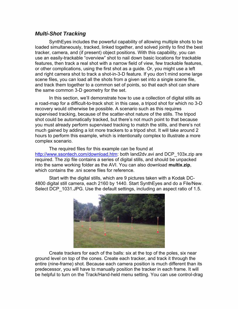
Multi-Shot Tracking SynthEyes includes the powerful capability of allowing multiple shots to be
loaded simultaneously, tracked, linked together, and solved jointly to find the best tracker, camera, and (if present) object positions. With this capability, you can use an easily-trackable “overview” shot to nail down basic locations for trackable features, then track a real shot with a narrow field of view, few trackable features, or other complications, using the first shot as a guide. Or, you might use a left and right camera shot to track a shot-in-3-D feature. If you don’t mind some large scene files, you can load all the shots from a given set into a single scene file, and track them together to a common set of points, so that each shot can share the same common 3-D geometry for the set.
In this section, we’ll demonstrate how to use a collection of digital stills as a road-map for a difficult-to-track shot: in this case, a tripod shot for which no 3-D recovery would otherwise be possible. A scenario such as this requires supervised tracking, because of the scatter-shot nature of the stills. The tripod shot could be automatically tracked, but there’s not much point to that because you must already perform supervised tracking to match the stills, and there’s not much gained by adding a lot more trackers to a tripod shot. It will take around 2 hours to perform this example, which is intentionally complex to illustrate a more complex scenario.
The required files for this example can be found at http://www.ssontech.com/download.htm: both land2dv.avi and DCP_103x.zip are required. The zip file contains a series of digital stills, and should be unpacked into the same working folder as the AVI. You can also download multix.zip, which contains the .sni scene files for reference.
Start with the digital stills, which are 9 pictures taken with a Kodak DC-4800 digital still camera, each 2160 by 1440. Start SynthEyes and do a File/New. Select DCP_1031.JPG. Use the default settings, including an aspect ratio of 1.5.
Create trackers for each of the balls: six at the top of the poles, six near
ground level on top of the cones. Create each tracker, and track it through the entire (nine-frame) shot. Because each camera position is much different than its predecessor, you will have to manually position the tracker in each frame. It will be helpful to turn on the Track/Hand-held menu setting. You can use control-drag
to make final positioning easier on the high-resolution still. It will be helpful to create the trackers in a consistent order, for example, from back left to front left, then back right to front right. After completing each track, Lock the tracker.
The manual tracking stage will take around an hour. The resulting file is available as multi1.sni.
Set up a coordinate system using the ground-level (cone) trackers. Set the front-left tracker as the Origin, the back-left tracker as a Lock Point at X=0,Y=50,Z=0, and the front-right tracker as an XY Plane tracker.
You can solve for this shot now: switch to the Solver panel and hit Go! You should obtain a satisfactory solution for the ball locations, and a rather erratic and spaced out camera path, since the camera was walked from place to place. (multi2.sni)
It is time for the second shot. On the Shot menu, select Add Shot (or File/Import/Shot). Select the land2dv.avi shot. If you have 256 MB or more of RAM memory on your machine, increase the queue length setting to 132 (the entire shot). Make sure interlacing is set to No; the shot was taken was a Canon Optura Pi in progressive scan mode.
Unless you have 512 MB or more of RAM, use the Shot menu to switch back to Camera 1. Select Edit Shot and set queue length to 1, so this shot will use less memory. Switch back to Camera 2.
Bring the camera view full-screen, go to the tracker panel, and begin tracking the same ball positions in this shot with bright-spot trackers. Set the Key spinner to 8, as the exposure ramps substantially during the shot. The balls provide low contrast, so some trackers are easiest to control from within the tracker view window on the tracker panel. The back-right ground-level ball is occluded by the front-left above-ground ball, so you do not have to track the back-right ball. It will be easiest to create the trackers in the same order as in the first shot. (multi3.sni)
Next, create links between the two sets of trackers, to tell SynthEyes what trackers were tracking the same feature. You will need a bare minimum of six (6) links between the shots. Switch to the coordinate system panel, and the Quad view. Move far enough into the shot that all trackers are in-frame.
To assign links, select a tracker from the AVI in the camera view. Go to the top view and zoom in to find the matching 3-D point from the first shot, and ALT-click it (Mac: Command-click). Select the next tracker in the camera view, and ALT-click the corresponding point in the Top view; repeat until all are assigned. If you created the trackers consistently, you can sequence through them in order. Another approach is to give each tracker a meaningful name. In this case, clicking the Target Point button will be helpful: it brings up a list of trackers to choose from.
A more subtle approach is to have matching names, then use the Track/Cross Link By Name menu item. Having truly identical names makes things confusing, so the cross link command ignores the first character of each

name. You can then name the trackers lWindowBL and rWindowBL and have them automatically linked. After setting up a number of matching trackers, select the trackers on the video clip, and select the Cross Link By Name menu item. Links will be created from the selected trackers to the matching trackers on the reference shot.
Notes on links: a shot with links should have links to only a single other shot, which should not have any links to other shots. You can have several shots link to a single reference.
After completing the links, switch to the Solver panel. Change the solver mode to Indirect, because this camera’s solution will be based on the solution initially obtained from the first shot.(multi4.sni)
Hit Go! SynthEyes will solve the two shots jointly, that is, find the point positions that match both shots best. Each tracker will still have its own position; trackers linked together will be very close to one another.
In the example, you should be able to see that the second (tripod) shot was taken from roughly the location of the second still. Even if the positions were identical, differences between cameras and the exact features being tracked will result in imperfect matches. However, the pixel positions will match satisfactorily for effect insertion. The final result is multi5.sni.

Finding Light Positions After you have solved the scene, you can optionally use SynthEyes to
calculate the position of, or at least direction to, principal lights affecting the scene. You might determine the location of a spotlight on the set, or the direction to the sun outdoors. In either case, knowing the lighting will help you match your computer-graphic scene to the live footage.
SynthEyes can use either shadows or highlights to locate the lights. For shadow tracking, you must track both the object casting the shadow, and the shadow itself, determining a 3-D location for each. For highlight tracking, you will track a moving highlight (mainly in 2-D), and you must create a 3-D mesh (generally from an external modeling application, or a SynthEyes 3-D primitive) that exactly matches the geometry on which the highlight is reflected.
Lights from Shadows Consider the two supervised trackers in the image below from the BigBall
example scene:
One tracks the spout of a teacup, the other tracks the spout’s shadow on
the table. After solving the scene, we have the 3-D position of both. The procedure to locate the light in this situation is as follows.
Switch to the Lighting Control Panel. Click the New Light button, then the New Ray button. In the camera view, click on the spout tracker, then on the tracker for the spout’s shadow.
We could turn on the Far-away light checkbox, if the light was the sun, so that the direction of the light is the same everywhere in the scene. Instead, we’ll leave the checkbox off, and instead set the distance spinner to 100, moving the light away that distance from the target.
The light will now be positioned so that it would cast a shadow from the one tracker to the next; you can see it in the 3-D views. The lighting on any mesh
objects changes to reflect this light position, and you see the shadows in the perspective view. You can repeat this process for the second light, since the spout casts two shadows. This scene is Teacup.sni.
If the scene contained two different teapot-type setups due to the same single light, you can place two rays on one light, and the 3-D position of the light will be triangulated, without any need for a distance.
SynthEyes handles another important case, where you have walls, fences, or other linear features casting shadows, but you can not say that a single point casts a shadow at another single point. Instead, you may know that a point casts a shadow somewhere on a line, or a line casts a shadow onto a point. This is tantamount to knowing that the light falls somewhere in a particular 3-D plane. With two such planes, you can identify the light’s direction; with four you may be able to locate it in 3-D.
To tell SynthEyes about a planar constraint, you must set up two different rays, one with the common tracker and one point on the wall/fence/etc., and the other ray containing the common tracker and the other point on the wall/fence/etc.
Lights from Highlights If you can place a mesh into the scene that exactly matches that portion of
the scene’s geometry, and if there is a specular highlight reflected from that geometry, you can determine the direction to the light, and potentially its position as well.
To illustrate, we’ll overview an example shot, BigBall. After opening the shot, it can be tracked automatically or with supervised trackers (symmetric trackers will work well). If you auto-track, kill all the trackers in the interior of the ball, and the reflections on the teapot as well.
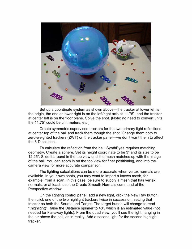
Set up a coordinate system as shown above—the tracker at lower left is
the origin, the one at lower right is on the left/right axis at 11.75”, and the tracker at center left is on the floor plane. Solve the shot. [Note: no need to convert units, the 11.75” could be cm, meters, etc.]
Create symmetric supervised trackers for the two primary light reflections at center top of the ball and track them though the shot. Change them both to zero-weighted trackers (ZWT) on the tracker panel—we don’t want them to affect the 3-D solution.
To calculate the reflection from the ball, SynthEyes requires matching geometry. Create a sphere. Set its height coordinate to be 3” and its size to be 12.25”. Slide it around in the top view until the mesh matches up with the image of the ball. You can zoom in on the top view for finer positioning, and into the camera view for more accurate comparison.
The lighting calculations can be more accurate when vertex normals are available. In your own shots, you may want to import a known mesh, for example, from a scan. In this case, be sure to supply a mesh that has vertex normals, or at least, use the Create Smooth Normals command of the Perspective window.
On the lighting control panel, add a new light, click the New Ray button, then click one of the two highlight trackers twice in succession, setting that tracker as both the Source and Target. The target button will change to read “(highlight)” Raise the Distance spinner to 48”, which is an estimated value (not needed for Far-away lights). From the quad view, you’ll see the light hanging in the air above the ball, as in reality. Add a second light for the second highlight tracker.

If you scrub through the shot, you’ll see the lights moving slightly as the camera moves. This reflects the small errors in tracking and mesh positioning. You can get a single average position for the light as follows: select the light, select the first ray if it isn’t already by clicking “>”, then click the “All” button. This will load up your CPU a bit as the light position is being repeatedly averaged over all the frames. This can be helpful if you want to adjust the mesh or tracker, but you can avoid further calculations by hitting the Lock button. If you later change some things, you can hit the Lock button to cause a recalculation.
In favorable circumstances, you will not need an approximate light
height or distance. The calculation SynthEyes is making with All or Lock selected is more than just an average—it is able to triangulate to find an exact light position. As it turns out, often, as in this example shot, the geometry of the lights, mesh, and camera does not make that accurately possible, because the shift in highlight position as the camera moves is generally quite small. (You can test this by turning the distance constraint down to zero and hitting Lock again.) But it may be possible if the camera is moving extensively, for example, dollying along the side of a car, when a good mesh for the car is available.

Building Meshes from Tracker Positions It can be useful to be able to build a mesh from the solved tracker
positions. Meshes can serve to catch or cast shadows, act as front-projection targets, etc. in your compositing or animation package, and these applications can be previewed within SynthEyes. The perspective window allows you to do so. You may want to increase the mesh density with the Add many trackers dialog, rapidly creating additional trackers after an initial auto-track and solve has been performed.
At any time, SynthEyes can have an Edit Mesh, which is different than a normally-selected mesh object. The Edit Mesh has its vertices and facets exposed for editing.
If, in the perspective view, you select a cylinder, for example, and click, Set as Edit Mesh, you’ll see the vertices. Right-click the Lasso Vertices mode and lasso-select some vertices, then right-click Mesh Operations/Delete selected faces, and you’ve knocked a hole in the cylinder. Right-click the Navigate mode.
Example: Ground Reconstruction Next, with the solved flyover_auto.sni shot open and the perspective
window open, right-click Lock to current camera, click anywhere to deselect everything, then right-click Set Edit Mesh and Mesh Operations/Convert to Mesh. All the trackers now are vertices in a new edit mesh. (If you had selected a group of trackers, only those trackers would have been converted.) Rewind to the beginning of the shot (shift-A), and right-click Mesh Operations/Triangulate. Right click unlock from camera. Click one of the vertices (not trackers) near the center, then control-middle-drag to rotate around the new mesh. Note that the triangulation occurs with respect to a particular point of view; a top-down view is preferable to a side-on one which will probably have an interdigitated structure rather than what you likely want.
Lock the view back to the camera. Click on the tracker mesh to select it. Select the 3-D control panel and click Catch Shadows. Select Cylinder as the object-creation type on the 3-D panel, and create a cylinder in the middle of the mesh object (it will actually be created on the ground plane). You will see the shadow on the tracker mesh. Use the cylinder’s handles to drag it around and the shadow will move across the mesh appropriately. For more fun, right-click Place mode and move the cylinder around on the mesh.
In your 3-D application, you will probably want to subdivide the mesh to a smoother form, unless you already have many trackers. A smoother mesh will prevent shadows from showing sharp bends due to the underlying mesh.
Front Projection Next, with the cylinder casting an interesting shadow on an irregular
surface, right-click Texturing/Rolling Front Projection. The mesh apparently
disappears, but the irregular shadow remains. This continues even if you scrub through the shot.
In short, the image has been “front projected” onto the mesh, so that it appears invisible. But, it continues to serve as a shadow catcher.
In this “Rolling Front Projection” mode, new U,V coordinates are being calculated on each frame to match the camera angle, and the current image is being projected, ensuring invisibility.
Alternatively, the “Frozen Front Projection” mode calculates U,V coordinates only once, when the mode is applied. Furthermore, the image from that frame continues to be applied for the rest of the frames as well. This kind of configuration is often used for 3-D Fix-It applications where a good frame is used to patch up some other ones, where a truck drives by, for example.
Because the image is projected onto a 3-D surface, some parallax can be developed as the shot evolves, often hiding the essentially 2-D nature of the fix. If the mesh geometry is accurate enough, this amounts to texture-mapping it with a live frame.
Furthermore, the U,V coordinates of the mesh can be exported and used in other animation software, along with the source-image frame as a texture, in the rare event it does not support camera mapping.
Changing Camera Path If you have a well-chosen grid of trackers, you may be able to fly another
camera along a similar camera path to the original, with the original imagery re-projected onto the mesh, to produce a new view. Usually you will have to model some parts of the scene fairly carefully, however.
Practical Details In practice, you will want to exercise much finer control over the building of
the mesh. The mesh built from the flyover trackers winds up with a lot of bumpiness due to the trees and sparsity of sampling. SynthEyes provides tools for building models more selectively.
The convert-to-mesh and triangulate tools operate only on selected trackers or vertices, respectively. Usually you will want to select only a subset of the trackers to triangulate. After doing so, you may find that you want to take out some facets and re-triangulate them differently to better reflect the actual world geometry or your planned use.
You can accomplish that by deleting the offending facets (after selecting them by selecting all their vertices), and then selectively re-triangulating.
Often an outlying tracker may need to be removed from the mesh, for example, the top of a phone pole that creates a “tent” in an otherwise mostly flat landscape. You can select that vertex, and right-click Remove and Repair.

Removed vertices are not deleted, to give you the opportunity to reconnect them. Use the Delete Unused Vertices operation to finally remove them.
Long triangles cause display problems in all animation packages, as interpolation across them does not work accurately. SynthEyes allows you to subdivide facets by placing a vertex at center, and converting the facet to three new ones, or subdivide the edges by putting a vertex at the center of each edge and converting each facet to four new ones.
Of course, there may not necessarily be a tracker where you need one to accurately present the geometry. Even if you used auto-tracking, and the Add many trackers dialog, you will probably want to add additional supervised trackers for particular locations. Use Convert to Mesh to add them to the existing edit mesh.
Also, you can add vertices directly using the Add Vertices tool, or move them around with the move tool. Both of these rely on the grid to establish the basic positioning, typically using the Grid menu’s Align to Trackers/Vertices option. You can then add vertices on the grid, move them along it, or move them perpendicular to it by shift-dragging. You can move multiple vertices by lasso-selecting them, or shift-clicking them from Move mode.
After we get into object tracking, you will see that you can use the mesh construction process to generate starting points for object modeling efforts as well.
Depth Maps With a mesh constructed from the tracker positions, you can generate a
depth map or movie to feed to 3-D compositing applications. Once you have completed tracking and created the mesh, open the
perspective window and begin creating a Preview Movie. Select the Depth channel to be written and select an output file name and format, either an OpenEXR or BMP file sequence (BMPs are OK on a Mac). Unless the output is OpenEXR, you must turn off the RGB data.
Click Start, and the depth map sequence will be produced. Note that you may need to manipulate it in your compositing application if that application interprets the depth data differently.

Curve Tracking and Analysis in 3-D While the bulk of SynthEyes is concerned with determining the location of
points in 3-D, sometimes it can be essential to determine the shape of a curve in 3-D, even if that curve has no trackable points on it, and every point along the curve appears the same as every other. For example, it might be the curve of a highway overpass to which a car chase must be added, the shape of a window opening on a car, or the shape of a sidewalk on a hilly road, which must be used as a 3-D masking edge for an architectural insert.
In such situations, acquiring the 3-D shape can be a tremendous advantage, and SynthEyes can now bring it to you using its novel curve tracking and flex solving capability, as operated with the Flex/Curve Control Panel.
Terminology There’s a bit of new terminology to define here, since there are both 2-D
and 3-D curves being considered. Curve. This refers to a spline-like 2-D curve. It will always live on one
particular shot, and is animated with a different location on each frame. Flex. A spline-like 3-D curve. A flex resides in 3-D, though it may be
attached to a moving object. One or more curves will be attached to the flex; those curves will be analyzed to determine the 3-D shape of the flex.
Rough-in. Placing control-point keys periodically and approximately. Tuning a curve. Adjusting a curve so it matches edges exactly.
Overview Here’s the overall process for using the curve and flex system to
determine a 3-D curve. The quick synopsis that we will get the 2-D curves positioned exactly on each frame throughout the shot, then run a 3-D solving stage. Note that the ordering of the steps can be changed around a bit, and additional wrinkles added, once you know what you are doing — this is the simplest and easiest to explain.
1. Open the shot in SynthEyes 2. Obtain a 3-D camera solution, using automatic or supervised tracking 3. At the beginning of the shot, create a (2-D) curve corresponding to the
flex-to-be. 4. “Rough-in” the path of the curve, with control-point animation keys
throughout the shot. There is a tool that can help do this, using the existing point trackers.
5. Tune the curve to precisely match the underlying edges (manual or automatic).
6. Draw a new flex in an approximate location. Assign the curve to it.

7. Configure the handling of the ends of the flex. 8. Solve the flex 9. Export the flex or convert it to a series of trackers.
Shot Planning and Limitations Determining the 3-D position of a curve is at the mercy of underlying
mathematics, just as is the 3-D camera analysis performed by the rest of SynthEyes. Because every point along a curve/flex is equivalent, there is necessarily less information in the curve data than in a collection of trackers.
As a result, first, flex analysis can only be performed after a successful normal 3-D solve that has determined camera path and field of view. The curve data can not help obtain that solve; it does not replace and is not equivalent to the data of several trackers.
Additionally, the camera motion must be richer and more complex than for a collection of trackers. Consider a flex consisting of a horizontal line, perhaps a clothesline or the top of a fence. If the camera moves left to right so that its path is parallel to the flex, no 3-D information (depth) can be produced for the flex. If the camera moves vertically, then the depth information can be obtained. The situation is reversed for a vertical line: a vertical camera motion will not produce any depth information.
Generally, both the shape of the flex and camera path will be more complex, and you will need to ensure that the camera path is sufficiently complex to produce adequate depth information for all of the flex. If the flex is circular, and the camera motion horizontal, then the top and bottom of the circle will not have well-defined depth. The flex will prefer a flat configuration, which is often, but not necessarily, correct.
Note that a simple diagonal motion will not solve this problem: it will not explore the depth in the portion of the circle that is parallel to the motion path. The camera path must itself curve to more completely identify the depth all the way around the circle — hence the comment that the camera motion must itself be more complex than for point tracking.
Similarly, tripod (nodal pan) shots are not suitable for use with the curve & flex solving system. As with point tracking, tripod shots do not produce any depth information.
Flexes and curves are not closed like the letter O — they are open like the letter U or C. Also, they do not contain corners, like a V. Nor do they contain tangency handles, since the curvature is controlled by SynthEyes.
Generally, the curve will be set up to track a fairly visible edge in the image. Very marginal edges can still be used and solved to produce a flex, if you are willing to do the tracking by hand.

Initial Curve Setup Once you have identified the section of curve to be tracked and made into
a 3-D flex, you should open the Flex Control Panel, which contains both flex and curve controls, and select the camera view.
Click the New Curve button, then, in the Camera View, click along the section of curve to be tracked, creating control points as you go. Place additional control points in areas of rapid curvature, and at extremal points of the curve. Avoid area where there is no trackable edge if possible.
When you have finished with the last control point, right-click to exit the curve creation mode.
Roughing in the Curve Keys Next, we will approximately position the curve to track the underlying
edge. This can be done manually or automatically, if the situation permits. Manual Roughing For manual roughing, you move through the shot and periodically re-set
the position of the curve. By starting at the ends, and then successively correcting the position at the most extremely-wrong positions within the shot, usually this isn’t too time consuming (unless the shot is a jumpy hand-held one). SynthEyes splines the control point positions over time.
To re-set the curve, you can drag the entire curve into an approximate position, then adjust the control points as necessary. If you find you need additional control points, you can shift-click within the curve to create them.
You should monitor the control point density so that you don’t bunch many of them in the same place. But you do not have to worry about control points “chattering” in position along the curve. This will not affect SynthEyes or the resulting flex.
Automatic Roughing SynthEyes can automatically rough the curve into place with a special tool
— as long as there is a collection of trackers around the curve (not just one end), such that the trackers and curve are all roughly on the same plane.
When this is the case, shift-select all the trackers you want to use, click the Rough button on the Flex control panel, then click the curve to be roughed into place.
The Rough Curve Import panel will appear, a simple affair.

The first field asks how many trackers must be valid for the roughing
process to continue. In this case, 5 trackers were selected to start. As shown, it will continue even if only one is valid. If the value is raised to 5, the process will stop once any tracker becomes invalid. If only a few trackers are valid (especially less than 4), less useful predictions of the curve shape can be made.
The Key every N frames setting controls how often the curve is keyed. At the default setting of 1, a key will be placed at every frame, which is suitable for a hand-held shot, but less convenient to subsequently refine. For a smooth shot, a value of 10-20 might be more appropriate.
The Rough Curve Importer will start at the current frame, and begin creating keys every so often as specified. It will stop if it reaches the end of the shot, if there are too few trackers still valid, or if it passes by any existing key on the curve. You can take advantage of this last point to “fill in” keys selectively as needed, using different sets of trackers at different times, for example.
After you’ve used the Rough Curve Import tool, you should scrub through the shot to look for any places where additional manual tweaking is required.
The curve may go offscreen or be obscured. If this happens, you can use the curve Enable checkbox to disable the curve. Note that it is OK if the curve goes partly offscreen, as long as there Is enough information to locate it while it is onscreen.
Curve Tuning Once the curve has been roughed into place, you’re ready to “tune” it to
place it more accurately along the edge. Of course, you can do this all by hand, and in adverse conditions, that may be necessary. But it is much better to use the automated Tune tool.
You can tune either a single frame, with the Tune button, or all of the frames using of course the All button. When a curve is tuned on a frame, the curve control points will latch onto the nearby edge.
For this reason, before you begin tuning, you may wish to create additional control points along the curve, by shift-clicking it.

The All button will bring up a control panel that controls both the single- and multi-frame tuning. If you want to adjust the parameters without tuning all the frames, simple close the dialog instead of hitting its Go button.
You can adjust to edges of different widths, control the distance within
which the edge is searched, and alter the trade-off between a large distant edge, and a smaller nearby one. Clearly, it is going to be easier to track edges with no nearby edges of similar magnitude.
The control panel allows you to tune all frames (potentially just those within the animation playback range), only the frames that already have keys (to tune your roughed-in frames), or only the frame that do not have keys (to preserve your previously-keyed frames).
You can also tell the tracking dialog to use the tuned locations as it estimates (using splining) where the curve is in subsequent frames, by turning on the Continuous Update checkbox. If you have a simple curve well-separated from confounding factors, you can use this feature to track a curve through a shot without roughing it in first. The drawback of doing this is that if the curve does get off course, you can wind up with many bad keys that must be repaired or replaced. [You can remove erroneous keys using Truncate.] With the Continuous Update box off, the tuning process is more predictable, relying solely on your roughed-in animation.
Flex Creation With your curve(s) complete, you can now create a flex, which is the 3-D
splined curve that will be made to match the curve animation. The flex will be created in 3-D in a position that approximately matches its actual position and shape. It is usually most convenient to open the Quad view, so that you can see the camera view at the same time you create the flex in one of the 3-D views (such as the Top view).

Click the New Flex button, then begin clicking in the chosen 3-D view to lay out a succession of control points. Right-click to end the mode. You can now adjust the flex control points as needed to better match the curve. You should keep the flex somewhat shorter than the curve.
To attach the curve to the flex, select the curve in the camera view, then, on the flex control panel, change the parent-flex list box for the curve to be your flex. (Note: if you create the flex, then the curve while the flex is selected, the curve is automatically connected to the flex.)
Flex Endpoints The flex’s endpoints must be “nailed down” so that the flex can not just
shrivel up along the length of the curve, or pour off the end. The ends are controlled by one of several different means:
1. the end of the flex can stay even with its initial position, 2. the end of the flex can stay even with a specific tracker, or 3. the end of the flex can exactly match the position of a tracker.
The first method is the default. The last method is possible only if there is a tracker at the desired location; this arises most often when several lines intersect. You can track the intersection, then force all of the flexes to meet at the same 3-D location.
To set the starting or ending tracker location for a flex, click the Start Pt or End Pt button, then click on the desired tracker. Note that the current 3-D location of the tracker will be saved, so if you re-track or re-solve, you will need to reset the endpoint.
The flex will end “even” with the specified point, meaning so that the point is perpendicular to the end of the flex. To match the position exactly, turn on the Exact button.
Flex Solving Now that you’ve got the curve and flex set up, you are ready to solve. This
is very easy — click the Solve button (or Solve All if you have several flexes ready to be solved).
After you solve a flex, the control points will no longer be visible—they are replaced by a more densely sample sequence of non-editable points. If you want to get back to the original control points to adjust the initial configuration, you can click Clear.
Flex Exports Once you have solved the flex, you can export it. At present, there are two
principal export paths. The flexes are not currently exported as part of regular tracker exports.

First, you can convert the flex into a sequence of trackers with the Convert Flex to Trackers script on the Track menu. The trackers can be used exported directly, or, more usefully, you can use them in the Perspective window to create a mesh containing those trackers. For example, on a building project where the flex is the edge of the road, you can create a ground mesh to be landscaped, and still have it connect smoothly with the road, even if the road is not planar.
Second, you can export the coordinates of the points along the flex into a text file using the Flex Vertex Coordinates exporter. Using that file is up to you, though it should be possible to use it to create paths in most packages.

Motion Capture and Face Tracking SynthEyes offers the exciting capability to do full body and facial motion
capture using conventional video or film cameras. First, a clarification. The moving-object tracking discussed previously is
very effective for tracking a head, when the face is not doing all that much, or when trackable points have been added in places that don’t move with respect to one another (forehead, jaws, nose). The moving-object mode is good for making animals talk, for example. By contrast, motion capture is used when the motion of the moving features is to be determined, and will then be applied to an animated character. For example, use motion capture of an actor reading a script to apply the same expressions to an animated character. Moving-object tracking requires only one camera, while motion capture requires several calibrated cameras.
Second, we need to establish a few very important points: this is not the kind of capability that you can learn on the fly as you do that important shoot, with the client breathing down your neck. This is not the kind of thing for which you can expect to glance at this manual for a few minutes, and be a pro. Your head will explode. This is not the sort of thing you can expect to apply to some musty old archival footage, or using that old VHS camera at night in front of a flickering fireplace. This is not something where you can set up a shoot for a couple of days, leave it around with small children or animals climbing on it, and get anything usable whatsoever. This is not the sort of thing where you can take a SynthEyes export into your animation software, and expect all your work to be done, with just a quick render to come. And this is not the sort of thing that is going to produce the results of a $250,000 custom full body motion capture studio with 25 cameras.
With all those dire warnings out of the way, what is the good news? If you do your homework, do your experimentation ahead of time, set up technically solid cameras and lighting, read the SynthEyes manual so you have a fair understanding what the SynthEyes software is doing, and understand your 3-D package well enough to set up your character or face rigging, you should be able to get excellent results.
In this manual, we’ll work through a sample facial capture session. The techniques and issues are the same for full body capture, though of course the tracking marks and overall camera setup for body capture must be larger and more complex.
Introduction To perform motion capture of faces or bodies, you will need at least two
cameras trained on the performer from different angles. Since the performer’s head or limbs are rotating, the tracking features may rotate out of view of the first two cameras, so you may need additional cameras to shoot more views from behind the actor.

The fields of view of the cameras must be large enough to encompass the entire motion that the actor will perform, without the cameras tracking the performer (OK, experts can use SynthEyes for motion capture even when the cameras move, but only with care).
You will need to perform a calibration process ahead of time, to determine the exact position and orientation of the cameras with respect to one another (assuming they are not moving). We’ll show you one way to achieve this, using some specialized but inexpensive gear.
Very Important: You’ll have to ensure that nobody knocks the cameras out of calibration while you shoot calibration or live action footage, or between takes.
You’ll need to be able to resynchronize the footage of all the cameras in post. We’ll tell you one way to do that.
Generally the performer will have tracker markers attached to ensure the best possible and most reliable data capture. The exception to this would be if one of the camera views must also be used as part of the final shot, for example, a talking head that will have an extreme helmet added. In this case, markers can be used where they will be hidden by the added effect, and where they will not be, either natural facial features can be used (think HD or film), or markers can be used and removed as an additional effect.
After you solve the calibration and tracking in SynthEyes, you will wind up with a collection of trajectories showing the path through space of each individual feature. When you do moving-object tracking, the trackers are all rigidly connected to one another, but in motion capture, each tracker follows its own individual path.
You will bring all these individual paths into your animation package, and will need to set up a rigging system that makes your character move in response to the the tracker paths. That rigging might consist of expressions, Look At controllers, etc, it’s up to you and your animation package.
Camera Types Since the fields of view must encompass the entire performance, at any
time the actor is usually a small portion of the frame. This makes progressive DV, HD, or film source material strongly suggested.
Progressive-scan cameras are strongly recommended, to avoid the factor of two loss of vertical resolution due to interlacing. This is especially important since the tracking markers are typically small and can slip between scan lines.
While it may make operations simpler, the cameras do not have to be the same kind, have the same aspect ratio, or have the same frame rate.
Resist the urge to use that old consumer-grade analog videotape camera --- the recording process will not be stable enough for good results.

Lens distortion will substantially complicate calibration and processing. To minimize distortion, use high-quality lenses, and do not operate them near their maximum field of view, where distortion is largest. This suggests that you avoid trying to squeeze into the smallest possible or bare minimum studio space.
Camera Placement The camera placements must address two opposing factors: one, that the
cameras should be far apart, to produce a parallax disparity to produce the 3-D paths, and the cameras should be close together, so that they can simultaneously observe as many trackers as possible.
You’ll probably need to experiment with placement to gain experience, keeping in mind the performance to be delivered.
Cameras do not have to be placed in any discernable pattern. If the performance warrants it, you might want coverage from up above, or down below.
If any cameras will move during the performance, they will need their own set of stationary tracking markers, to recover their trajectory in the usual fashion. This will reduce accuracy compared to a carefully calibrated stationary camera.
Lighting Lighting should be sufficient to keep the markers well illuminated, avoiding
shadowing. When video cameras are involved, the lighting should be enough to be able to keep the shutter time of the cameras as low as possible, compatible with good image quality.
Calibration Requirements and Fixturing In order for motion tracking footage to be solved, the camera positions,
orientations, and fields of view must be determined, independent of the “live” footage, as accurately as possible.
To do this, we will use a process based on moving-object tracking. A calibration object is moved in the field of view of all the cameras, and tracked simultaneously.
To get the most data fastest and easiest, we constructed a prop we call a “porcupine” out of a 4” Styrofoam ball, 20-gauge plant stem wires, and small 7 mm colored pom-pom balls, all obtained from a local craft shop for under $5. Lengths of wire were cut to varying lengths, stuck into the ball, and a pom-pom glued to the end using a hot glue gun. Retrospectively, it would have been cleverer to space two balls along the support wire as well, to help set up a coordinate system.

The porcupine is hung by a support wire in the location of the performer’s
head, then rotated as it is recorded simultaneously from each camera. The porcupine’s colored pom-poms can be viewed virtually all the time, even as they spin around to the back, except for the occasional occlusion.
Similar fixtures can be built for larger motion capture scenarios, perhaps using dolly track to carry a wire frame. It is important that the individual trackable features on the fixture not move with respect to one another: their rigidity is required for the standard object tracking.
The path of the calibration fixture does not particularly matter.
Camera Synchronization The timing relationship between the different cameras must be
established. Ideally, all the cameras would all be gen-locked together, snapping each image at exactly the same time. Instead, there are a variety of possibilities which can be arranged and communicated to SynthEyes during the setup process.
If the cameras are all video cameras, they can be gen-locked together to all take pictures identically. This option is “Sync Locked.”
If you have a collection of video cameras, they will all take pictures at exactly the same (crystal-controlled) rate. However, one camera may always be taking pictures a bit before the other, and a third camera may always be taking pictures at yet a different time than the other two. The option is “Crystal Sync.”

If you have a film camera, it might run a little more or a little less that 24 fps, not particularly synchronized to anything. This will be referred to as “Loose Sync.”
In a capture setup with multiple cameras, one can always be considered to be Sync Locked, and serve as a reference. If it is a video camera, other video cameras are in Crystal Sync, and any film camera would be Loose Sync.
If you have a film camera that will be used in the final shot, it should be considered to be the sync reference, with Sync Locked, and any other cameras are in Loose Sync.
The beginning and end of each camera’s shot of the calibration and performance must be identified to the nearest frame. This can be achieved with a clapper board or electronic slate. The low-budget approach is to use a flashlight or laser pointer flash to mark the beginning and end of the shot.
Camera Calibration Process We’re ready to start the camera calibration process, using the two shot
sequences LeftCalibSeq and RightCalibSeq. You can start SynthEyes and do a File/New for the left shot, and then Add Shot to bring in the second. Open both with Interlace=Yes, as unfortunately both shots are interlaced. Even though these are moving-object shots, for calibration they will be solved as moving-camera shots.
You can see from these shots how the timing calibration was carried out. The shots were cropped right before the beginning of the starting flash, and right after the ending flash, to make it obvious what had been done. Normally, you should crop after the starting flash, and before the ending flash.
You can use the Image Preprocessing panel’s Region-of-interest capability to reduce memory consumption if you don’t have much.
You should track a substantial fraction of the pom-poms in each camera view; you can then solve each camera to obtaining an orbiting path.
Next, we will need to set up a set of links between corresponding trackers in the two shots. The links must always be on the Camera02 trackers, to a Camera01 tracker. This can be achieved at least three different ways.
Matching Plan A: Temporary Alignment This is probably easiest, and we may offer a script to do the grunt work in
the future. Begin by assigning a temporary coordinate system for each camera, using
the same pom-poms in each camera. It is most useful to keep the porcupine axis upright (which is where pom-poms along the support wire would come in useful, if available); in this shot three at the very bottom of the porcupine were suitable.
With matching constraints for each camera, when you re-solve, you will obtain matching pairs of tracker points, one from each camera, located very close to one another.
Now, with Camera02 active and the Top view selected, you can click on each of Camera02’s tracker points, and then alt-click (or command-click) on the corresponding Camera01 point, setting up all the links.
After completing the linking, you should remove the constraints from Camera02.
Matching Plan B: Side by Side In this plan, you can use a viewport configuration with both a perspective
window and the camera view displayed simultaneously. Lock the perspective window to Camera01’s imagery, and make Camera02 active for the camera view.
You can now click the trackers in the camera(02) view, and alt-click the matching (01) tracker in the perspective window, establishing the links. This will take a little mental rotation to establish the right correspondences; the colors of the various pom-poms will help.
Matching Plan C: Cross Link by Name This plan is more trouble than it worth, most likely. You can assign names
to each of the pom-poms, so that the names differ only by the first character, then use the Cross-Link by Name menu item to establish links.
It is a bit of pain to come up with different names for the pom-poms, and do it identically for the two views, but this might be more reasonable for other calibration scenarios where it is more obvious which point is which.
Completing the Calibration We’re now ready to complete the calibration process. Change Camera02
to Indirectly solving mode. Note: the initial position of Camera01 is going to stay fixed, controlling the
overall positions of all the cameras. If you want it in some particular location, you can remove the constraints from it, reset its path from the 3-D panel, then move it around to a desired location
Solve the shot, and you have two orbiting cameras remaining at a fixed relative orientation as they orbit.
Run the Motion Capture Camera Calibration script from the Track menu, and the orbits will be squished down to single locations. Camera01 will be stationary at its initial location, and Camera02 will be jittering around another location, showing the stability of the offset between the two. The first frame of Camera02’s position is actually an average relative position over the entire shot; it is this location that must be accurately maintained.
You should save this calibration scene file (porcupine.sni); it will be the starting point for tracking the real footage. The calibration script also produces a script_output.txt file in a user-specific folder that lists the calibration data.
Body and Facial Tracking Marks Markers will make tracking faster, easier, and more accurate. On the
face, markers might be little Avery dots from an office supply store, “magic marker” spots, pom-poms with rubber cement(?), or grease paint. Note that small colored dots tend to lose their coloration in video images, especially with motion blur. Single-pixel-sized spots are less accurate than those that are several pixels across.
Markers should be placed on the face to reflect the underlying musculature and the facial rigging they must drive. Be sure to include markers on comparatively stationary parts of the head.
For body tracking, a typical approach is to put the performer in a black outfit (such as UnderArmor), and attach table-tennis balls as tracking features onto the joints. To achieve enough visibility, placing balls on both the top and bottom of the elbow may be necessary, for example. Because the markers must be placed on the outside of the body, away from the true joint locations, character rigging will have to take this into account.
Preparation for 2-D Tracking We’re ready to begin tracking the actual performance footage. Open the
final calibration scene file. Open the 3-D panel. For each camera, select the camera in the select-by-name dropdown list. Then hit Blast and answer yes to store the field of view data as well. Then, hit Reset twice, answering yes to remove keys from the field of view track also. The result of this little dance is to take the solved camera paths (as modified by the script), and make them the initial position and orientation for each camera, with no animation (since they aren’t actually moving).
Next, replace the shot for each camera with LeftFaceSeq and RightFaceSeq. Again, these shots have been cropped based on the light flashes, which would normally be removed. Set the End Frame for each shot to its maximum possible. Use an animated ROI on the Imaging Preprocessing panel so that you can keep both shots in RAM simultaneously. Hit Control-A and delete to delete all the old trackers. Set each Lens to Known to lock the field of view, and set the solving mode of each camera to Disabled, since the cameras are fixed at their calibrated locations.
We need a placeholder object to hold all the individual trackers. Create a moving object, Object01, for Camera01, then a moving object, Object02, for Camera02. On the Solving Panel, set Object01 and Object02 to the Individual mocap solving mode, and set the synchronization mode right below that.

Two-D Tracking You can now track both shots, creating the trackers into Object01 and
Object02 for the respective shots. If you don’t track all the markers, at least be sure to track a given marker either in both shots, or none, as a half-tracked marker will not help. The Hand-Held: Predict mode may be helpful here for the rapid facial motions. Frequent keying will be necessary when the motion causes motion blur to appear and disappear (a lot of uniform light and short shutter time will prevent the need for this).
Linking the Shots After completing the tracking, you must set up links. The easiest approach
will probably be to set up side-by-side camera and perspective views. Again, you should link the Object02 trackers to the Object01 trackers, not the other way around.
Doing the linking by name can also be helpful, since the trackers should have fairly obvious names such as Nose or Left Inner Eyebrow, etc.
Solving You’re ready to solve, and the Solve step should be very routine,
producing paths for each of the linked trackers. The final file is facetrk.sni. Afterwards, you can start checking on the trackers. You can scrub through
the shot in the perspective window, orbiting around the face. You can check the error curves in the Tracker Graphs window. By switching to Sort by Error mode, you can sequence through the trackers starting from those with the highest error.
Exports & Rigging When you export a scene with individual trackers, each of them will have a
key frame on each frame of the shot, animating the tracker path. It is up to you to determine a method of rigging your character to take
advantage of the animated tracker paths. The method chosen will depend on your character and animation software package. It is likely you will need some expressions (formulas) and some Look-At controls. For full-body motion capture, you will need to take into account the offsets from the tracking markers (ie balls) to the actual joint locations.
Modeling You can use the calculated point locations to build models. However, the
animation of the vertices will not be carried forward into the meshes you build. Instead, when you do a Convert to Mesh operation in the perspective window, the current tracker locations are frozen on that frame.
If desired, you can repeat the object-building process on different frames to build up a collection of morph-target meshes.

Merging Files and Tracks When you are working on scenarios with multiple shots or objects, you
may wish to combine different SynthEyes .sni files together. For example, you may track a wide reference shot, and want to use those trackers as indirect links for several other shots. You can save the tracked reference shot, then use the File/Merge option to combine it with each of several other files.
Alternatively, you can transfer 2-D or 3-D data from one file to another, in the process making a variety of adjustments to it as discussed in the second subsection. You can track a file in several different auto-track sections, and recombine them using the scripts.
File/Merge After you start File/Merge and select a file to merge, you will be asked
whether or not to rename the trackers as necessary, to make them unique. If the current scene has Camera01 with trackers Tracker01 to Tracker05, and the scene being merged also has Camera01 with trackers Tracker01 to Tracker05, then answering yes will result in Camera01 with Tracker01 to Tracker05 and Camera02 with Tracker06 to Tracker10. If you answer no, Camera01 will have Tracker01 to Tracker05 and Camera02 with Tracker01 to Tracker05.
Notice that as this example shows, cameras, objects, meshes, and lights are always renamed to be unique. Renaming is always done by appending a number: if the incoming and current scenes both have a TrashCan, the incoming one will be renamed to TrashCan1.
If you are combining a shot with a previously-tracked reference, you will probably want to keep the existing tracker names, to make it easiest to find matching ones. Otherwise, renaming them with yes is probably the least confusing unless you have a particular knowledge of the TrackerNN assignments (in which case, giving them actual names such as Scuff1 is probably best).
You might occasionally track one portion of a shot in one scene file, and track a different portion of the same shot in a separate file. You can combine the scene files onto a single camera as follows:
1. Open the first shot 2. File/Merge the second shot. 3. Answer yes to make tracker names unique (important!) 4. Select Camera02 from the Shot menu. 5. Hit control-A to select all its trackers. 6. Go to the Coordinate System Panel. 7. Change the trackers’ host object from Camera02 to *Camera01. 8. Delete any moving objects, lights, or meshes attached to
Camera02.

9. Select Remove Object on the Shot panel to delete Camera02. All the trackers will now be on the single Camera01. Notice how Remove
Object can be used to remove a moving object or a camera and its shot. In each case, however, any other moving objects, trackers, lights, meshes, etc, must be removed first or the Remove Object will be ignored.
Tracker Data Transfer You can transfer tracking data from file to file using SynthEyes export
scripts, File/Export/Export 2-D Tracker Paths, and File/Import/Import 2-D Tracker Paths. These scripts can be used to interchange with other programs that support similar tracking data formats. The scripts can be used to make a number of remedial transforms as well, such as repairing track data if the source footage is replaced with a new version that is cropped differently.
The simple data format, a tracker name, frame number, horizontal and vertical positions, and an optional status code, also permits external manipulations by UNIX-style scripts and even spreadsheets.
Exporting Initiate the Export 2-D Tracker Paths script, select a file, and a script-
generated dialog box will appear:
As can be seen, it affords quite a bit of control.
The first three fields control the range of frames to be exported, in this case, frames 10 from 15. The offset allows the frame number in the file to be somewhat different, for example, -10 would make the first exported frame appear to be frame zero, as if frame 10 was the start of the shot.

The next four fields, two scales and two offsets, manipulate the horizontal (U) and vertical (V) coordinates. SynthEyes defines these to range from -1 to +1 and from left to right and top to bottom. Each coordinate is multiplied by its scale and then the offset added. The normal defaults are scale=1 and offset=0. The values of 0.5 and 0.5 shown rework the ranges to go from 0 to 1, as may be used by other programs. A scale of -0.5 would change the vertical coordinate to run from bottom to top, for example.
The scales and offsets can be used for a variety of fixes, including changes in the source imagery. You’ll have to cook up the scale and offset on your own, though. Note that if you are writing a tracker file on SynthEyes and will then read it back in with a transform, it is easiest to write it with scale=1 and offset=0, then make changes as you read in, since if you need to try again you can retry the import, without having to reexport.
Continuing with the controls, Even when missing causes a line to be output even if the tracker was not found in that frame. This permits a more accurate import, though other programs are less likely to understand the file. Similarly, the Include Outcome Codes checkbox controls whether or not a small numeric code appears on each line that indicates what was found; it permits a more accurate import, though is less likely to be understood elsewhere.
The 2-D tracks box controls whether or not the raw 2-D tracking data is output; this is not necessarily mandatory, as you’ll see.
The 3-D tracks box controls whether or not the 3-D path of each tracker is included―this will be the 2-D path of the solved 3-D position, and is quite smooth. In the example, 3-D paths are exported and 2-D paths are not, which is the reverse of the default. When the 3-D paths are exported, an extra Suffix for 3-D can be added to the tracker names; usually this is _3D, so that if both are output, you can tell which is which.
Finally, the Extra Points box controls whether or not the 2-D paths of an extra helper points in the scene are output.
Importing The 2-D path import can be used to read the output of the 2-D exporter, or
from other programs as well. The import script offers a similar set of controls to the exporter:

The import runs roughly in reverse of the export. The frame offset is
applied to the frame numbers in the file, and only those within the selected first and last frames are stored.
The scale and offset can be adjusted; by default they are 1 and 0 respectively. The values of 2 and -1 shown undo the effect of the 0.5/0.5 in the example export panel.
If you are importing several different tracker data files into a single moving object or camera, you may have several different trackers all named Tracker1, for example, and after combining the files, this would be undesirable. Instead, by turning on Force unique names, each would be assigned a new unique name. Of course, if you have done supervised tracking in some different files to combine, you might well leave it off, to combine the paths together.
If the input data file contains data only for frames where a tracker has been found, the tracker will still be enabled past the last valid frame. By turning on Truncate enables after last, the enable will be turned off after the last valid frame.
After each tracker is read, it is locked up. You can unlock and modify it as necessary. The tracking data file contains only the basic path data, so you will probably want to adjust the tracker size, search size, etc.
If you will be writing your own tracker data file for this script to import, note that the lines must be sorted so that the lines for each specific tracker are contiguous, and sorted in order of ascending frame number. This convention makes everyone’s scripts easier. Also, note that the tracker names in the file never contain spaces, they will have been changed to underscores.
Transferring 3-D Paths The path of a camera or object can be exported into a plain file containing
a frame number, 3 positions, 3 rotations, and an optional zoom channel (field of view or focal length).
Like the 2-D exporter, the 3-D exporter provides a variety of options: First Frame. First frame to export Last Frame. Last frame to export. Frame Offset. Add this value to the frame number before storing it in the file. World Scaling. Multiplies the X,Y, Z coordinates, making the path bigger or
smaller. Axis Mode. Radio-buttons for Z Up; Y Up, Right; Y Up, Left. Adjust to select the
desired output alignment, overriding the current SynthEyes scene setting. Rotation Order. Radio buttons: XYZ or ZXY. Controls the interpretation of the 3
rotation angles in the file. Zoom Channel. Radio buttons: None, Field of View, Vertical Field of View, Focal
Length. Controls the 7th data channel, namely what kind of field of view data is output, if any.
Look the other way. SynthEyes camera looks along the –Z axis; some systems have the camera look along +Z. Select this checkbox for those other systems. The 3-D path importer has the same set of options. Though this seems
redundant, it lets the importer read flexibly from other packages. If you are writing from SynthEyes and then reading the same data back in, you can leave the settings at their defaults on both export and import (unless you want to time-shift too, for example). If you are changing something, usually it is best to do it on the import, rather than the export.
Transferring 3-D Positions You can output the trackers’ 3-D positions using the “Plain Trackers” script
with these options: Tracker Names. Radio buttons: At beginning, At end of line, None. Controls
where the tracker names are placed on each output line. The end of line option allows tracker names that contain spaces. Spaces are changed to underscores if the names are at the beginning of the line.
Include Extras. If enabled, any helper points are also included in the file. World Scaling. Multiplies the coordinates to increase or decrease overall
scaling. Axis Mode. Temporarily changes the coordinate system setting as selected.
On the input side, there is an Import Trackers option and an Import Helper Points option. Neither has any controls; they automatically detect whether the name is at the beginning or end of the line.
When importing trackers, the coordinates are automatically set up as a seed position on the tracker. You may want to change it to a Lock constraint mode as well. If a tracker of the given name does not exist, a new tracker will be created.

Batch File Processing The SynthEyes batch file processor lets you queue up a series of shots for
match-moving, over lunch or over night. Please follow these steps: 1. In SynthEyes, do a File/New and select the first/next shot. 2. Adjust shot settings in SynthEyes as needed, for example, set it to
zoom or tripod mode, adjust the blip threshold if contrast is poor, and do an initial export — the same kind will be used at the completion of batch processing.
3. Hit File/Submit for Batch. 4. Repeat from step 1 for each shot. 5. Start the SynthEyes batch file processor, from the Windows Start
menu, Programs, Andersson Technologies LLC, SynthEyes Batcher.
6. Wait for one or more files to be completed. 7. Open the completed files from the Batch output folder. 8. Complete shot tracking as needed, such as assigning a coordinate
system, followed by a Refine pass. While the batcher runs, you can continue to run SynthEyes interactively,
which is especially useful for setting up additional shots, or finishing previously-completed ones.
Note: it is more efficient to use the batcher to process one shot while you work on another one, instead of starting two windows of SynthEyes, because the batcher does not attempt to load the entire shot into your RAM. Because the batcher does not use playback RAM, most RAM is then available for your interactive SynthEyes window.
Details SynthEyes uses two folders for batch file processing: an input folder and
an output folder. Submit for Batch places them into the input folder; completed files are written to the output folder, and the input file removed. You can set the location of the input and output folders from the Preferences panel.

SynthEyes Reference Material System RequirementsInstallation and RegistrationCustomer Care Features and Automatic UpdateViewport Layout ManagerWindow Feature Reference Perspective Window ReferenceControl Panel ReferenceMenu ReferencePreferences and Scene Settings ReferenceKeyboard ReferenceSupport
System Requirements
PC • Intel or AMD “x86” processor with SSE2, such as Pentium 4, Athlon 64,
Opteron, or Core/Core Duo. Note: Whereas on earlier versions SSE2 capability made SynthEyes run faster, SSE2 is a requirement for SynthEyes 2007. This requirement lets 2007 run faster on almost everyone’s machine, but old computers will not be able to run the new SynthEyes 2007.
• Windows XP; 2000, may run in 98 or Me. Supports XP’s 3GB mode. • 32-bit version runs under Windows XP 64 Pro. A separate 64-bit
SynthEyes version is available. • 1 GB RAM typical. 512 MB suggested minimum. • Mouse with middle scroll wheel/button. See the viewport reference section
for help using a trackball. • 1024x768 or larger display, 24 or 32 bit color, with OpenGL support. Large
multi-head configurations require graphics cards with sufficient memory. • DirectX 8.x or later recommended, required for DV and usually MPEG. • Quicktime 5 or later recommended, required to read .mov files. • A supported 3-D animation or compositing package to export paths and
points to. Can be on a different machine, even a different operating system, depending on the target package.
• A user familiar with general 3-D animation techniques such as key-framing.

Mac OS X • Intel Mac, G5 Mac or G4 Mac (marginal). • 1 GB RAM typical. 512 MB RAM suggested minimum. • 3 button mouse with scroll wheel. See the viewport reference section for
help using a trackball or Microsoft Intellipoint mouse driver. • 1024x768 or larger display, 24 or 32 bit color, with OpenGL support. Large
multi-head configurations require graphics cards with sufficient memory. • Mac OS 10.3.x or later • A supported 3-D animation or compositing package to export paths and
points to. Can be on a different machine, even a different operating system, depending on the target package.
• A user familiar with general 3-D animation techniques such as key-framing.
Interchange The Mac OSX versions can read SynthEyes files created on Windows and
vice versa. Note that Windows, 64-bit Windows, Intel Mac, and Power PC Mac OSX licenses must be purchased separately; licenses are not cross-platform.

Installation and Registration Following sections describe installation for the PC and, separately, Mac.
After installation, follow the directions in the Registration page to activate the product.
PC Installation Please uninstall SynthEyes Demo before installing the actual product. To install a downloaded SynthEyes, run the installer synsetup.exe, or
insert the CD. You can install to the default location, or any convenient location. The
installer will create shortcuts on the desktop for the SynthEyes program and HTML documentation.
If you have a trackball or tablet, you may wish to turn on the No middle-mouse preference setting to make alternate mouse modes available. See the viewport reference section. You should turn on Enhance Tablet Response if you have trouble stopping playback or tracking (Wacom appears to have fixed the underlying issue in recent drivers, so getting a new tablet driver may be another option.)
Proceed to the Registration section below.
PC Fine Print If you receive this error message:
"1155: File C:\... ...\INSTMSIW.EXE not found" then you need to install Microsoft’s Windows Installer 2.0 package on your machine before installing SynthEyes (this prerequisite is omitted from the SynthEyes download because it adds 2 MB, but is needed only rarely, on old machines).
You can download the installer module from the link below, or if Microsoft changes its site, search for “Windows Installer 2.0 Redistributable” in the Microsoft Downloads area. This version is for Windows 2000 and NT; there is a link to the 95/98/ME version on this page. The installer is already built into Windows XP.
http://www.microsoft.com/downloads/details.aspx?FamilyID=4b6140f9-2d36-4977-8fa1-6f8a0f5dca8f&DisplayLang=en - filelist
NOTE: If you receive this error message: Error 1327.Invalid Drive E:\ (or other drive)
then Windows Installer wants to check something on that drive. This can occur if you have a Firewire, network, or flash drive with a program installed to it, or an important folder such as My Documents placed on it, if the drive is not turned on or connected. The easiest cure is to turn the device on or reconnect it.

This behavior is part of Windows, see http://support.installshield.com/kb/view.asp?articleid=q107921 http://support.microsoft.com/default.aspx?scid=kb;en-us;282183
PC - DirectX SynthEyes requires Microsoft’s DirectX 8 or later to be able to read DV
and MPEG shots. DirectX is a free download from Microsoft and is already a component of many current games and applications. You may be able to verify that you already have it by searching for the DirectX diagnostic tool dxdiag.exe, located in \windows\system or \winnt\system32. If you run it, the system tab shows the DirectX version number at the bottom of the system information.
To download and install DirectX, go to http://www.microsoft.com and search for DirectX. Select a DirectX Runtime download for your operating system. The current version is DirectX 9.0c. Download (~ 8 MB) and install DirectX per Microsoft’s directions.
PC - QuickTime If you have shots contained in QuickTime™ (Apple) movies (ie .mov files),
you must have Apple’s QuickTime installed on your computer. If you use a capture card that produces QuickTime movies, you will already have QuickTime installed. SynthEyes can also produce preview movies in QuickTime format.
You can download QuickTime from http://www.apple.com/quicktime/download/
Quicktime Pro is not required for SynthEyes to read or write files.
Mac OS X Installation 1. Download the SynthEyes.dmg file to a convenient location on the Mac. 2. Double-click it to open it and expose the SynthEyes installation package. 3. Double-click the installation bundle to launch the install. 4. Proceed through a normal install; you will need root permissions. 5. Eject the .dmg file from the finder; it will be deleted. 6. Start SynthEyes from your Applications folder. You can create a shortcut
on your desktop if you wish. 7. Proceed to the Registration directions below.
Note that pictures throughout this document are based on the PC version; the Mac version will be very similar. In places where an ALT-click is called for on a PC, a Command-click should be used on the Mac, though these should be indicated in this manual.
If you have a trackball or Microsoft’s Intellipoint mouse driver, you may wish to turn on the No middle-mouse preference setting to make alternate

mouse modes available. See the viewport reference section. You should turn on Enhance Tablet Response if you have trouble stopping playback or tracking (Wacom appears to have fixed the underlying issue in recent drivers, so getting a new tablet driver may be another option.)
Registration and Authorization Overview After you order SynthEyes, you need to register to receive your permanent
program authorization data. For your convenience, some temporary registration data is automatically supplied as part of your order confirmation, so you can put SynthEyes immediately to work. The overall process (described in more detail later) is this:
1. Order SynthEyes 2. Receive order confirmation with download information and
temporary authorization. 3. Download and install SynthEyes 4. Start SynthEyes, fill out registration form, and send data to
Andersson Technologies LLC. 5. Restart SynthEyes, enter the temporary authorization data. 6. Wait for the permanent authorization data to arrive. 7. Start SynthEyes and enter the permanent authorization data.
Registration When you first start SynthEyes, a form will appear for you to enter
registration information. Alternatively, if you’ve entered the temporary authorization data first, you can access the registration dialog from the Help/Register menu item.

Proceed as follows:
1. Use copy and paste to transfer the serial number (starts with SN- on PC, S6- on Win64, IM- on Intel Mac, or SM- on PPC Mac) from the email confirmation of your purchase to the form.
2. Fill out the remainder of the form. Sorry if this seems redundant to the original order form, but it is necessary. This data should correspond to the user of the software. If the user has no clear relationship to the purchaser (a freelancer, say), please have the purchaser email us to let us know, so we don’t have to check later.
3. Hit OK, and SynthEyes will place a block of data onto the clipboard. 4. An email composition window will now appear, using your system’s
default email program. [If this does not happen, or to use a different emailer, create a new message entitled “SynthEyes Registration” addressed to [email protected].] Click inside the new- message window’s text area, then hit control-V (command-V on Mac) to paste the information from SynthEyes into the message.
5. If you are re-registering, after getting a new workstation, say, or are not the person originally purchasing the software, please add a note to that effect to the mail.
6. Send the e-mail. 7. You will receive an e-mail reply, typically the next business day,
containing the authorization data. Be sure to save the mail for future reference.

Authorization 1. View the email containing the authorization data. 2. Highlight the authorization information — everything from the angle
bracket “<” to the bracket “>” and including both brackets — in your e-mail program, and select Edit/Copy in your mail program. Note: the serial number (SN-, IM-, etc) is not part of the authorization data but is included next to it only for reference, especially for multiple licenses.
3. Start SynthEyes. If the registration dialog box appears, click the Use license on Clipboard button. If your temporary registration is still active, the registration dialog will not appear, so click Help/Authorize instead.
4. PC: if you get a message that you must be the administrator, but you are already the administrator, please contact support—security software on your machine is over-reaching.
5. A “Customer Care Login Information” dialog will appear. You should enter the support login and password that also came in the email with the authorization data. The user ID looks like jan02, and the password looks like jm323kx (these two will not work, use the ones from your mail). Note: if you have an evaluation license, you should hit Cancel on this panel.
6. SynthEyes will acknowledge the data, then exit. When you restart it, you should see your permanent information listed on the splash screen, and you’re ready to go.
PC Uninstallation Like other Windows-compatible programs, use the Add/Remove Programs
tool from the Windows Control Panel to uninstall SynthEyes.
Mac Uninstallation Delete the folders /Applications/SynthEyes, /Library/Application
Support/SynthEyes, and /Users/YourName/Library/Applications Support/SynthEyes.
Customer Care Features and Automatic Update SynthEyes features an extensive customer care facility, aimed at helping
you get the information you need, and helping you stay current with the latest SynthEyes builds, as easily as possible.
These facilities are accessed through 3 buttons on the main toolbar, and a number of entries on the Help menu.
These features require internet access during use, but internet access is not required for normal SynthEyes operation. You can use them with a dialup line, and you can tell SynthEyes to use it only when you ask.
We strongly recommend using these facilities, based on past customer experience! Note: some features operate slightly differently or are not available from the demonstration version of the software.
Customer Care Setup The auto-update, messaging, and suggestions features all require access
information to the customer-only web site to operate. The necessary login and password arrive with your SynthEyes authorization data (that big <….> thing), and you are prompted to enter them immediately after authorizing, or by selecting the Help/Set Update Info menu item. Customer Care uses the same login information as for accessing the support site.
If the D/L button is red when you start SynthEyes or check for updates, internet operations are failing. You should check your login information, if it is the first time, or check that you are really connected to the internet.
Also, if you have an Internet firewall program on your computer, you must permit SynthEyes to connect to the internet for the customer-care features to operate. You’ll have to check with your firewall software’s manual or support for details.
The customer care facility also uses the full serial number, as recorded when you registered. If the customer care access if failing and you’re sure there is no firewall problem, you can do a mock re-registration — Help/Register, fill out the form being sure to include the complete correct serial number, hit OK on the registration dialog — but don’t send an email to Andersson Technologies LLC.
Checking for Updates The update info dialog allows you to control how often SynthEyes checks
for updates from the ssontech.com web site. You can select never, daily, or on startup, with daily the recommended selection.
SynthEyes automatically checks for updates when it starts up, each time in “on startup” mode, but only the first time each day in “daily” mode. The check is performed in the background, so that it does not slow you down.

You can easily check for updates manually, especially if you are in “never” mode. Click the D/L button on the main toolbar, or Help/Check for updates.
Automatic Downloads SynthEyes checks to determine the latest available build on the web site.
If the latest build is more current than its own build, SynthEyes launches a download of the new version. The download takes place in the background as you use SynthEyes. The D/L button will be Yellow during the download.
Once the download is complete, the D/L button will turn green. When you have reached a convenient time to install the new version, click the D/L button or select the Help/Install Updated menu item. After making sure your work is saved, and that you are ready to proceed, SynthEyes closes and starts the new installer.
The same process occurs when you check for updates manually, with a few more explanatory messages.
Messages from Home The Msg button and Help/Read Messages menu item are your portal to
special information from Andersson Technologies LLC to bring you the latest word of updated scripts, tutorials, operating techniques, etc.
When the Msg button turns green, new messages are available; click it and they will appear in a web browser window! You can click it again later too, if you need to re-read something.
Suggestions We maintain a feature-suggestion system to help bring you the most
useful and best-performing software possible. Click the Sug button on the toolbar, or Help/Suggest a Feature menu item.
This miniature forum not only lets you submit requests, but comment and vote on existing feature suggestions. (This is not the place for technical support questions, however, please don’t clog it up with them.)
Demo version customers: this area is not available. Send email to support instead. Past experience has shown that many suggestions from demo customers are already in SynthEyes.
Web Links The Help menu contains a number of items that bring up web pages from
the www.ssontech.com web site for your convenience, including the main home page, the tutorials page, and the forum.

E-Mail Links The Help/Tech Support Mail item brings up an email composition window
preaddressed to technical support. Please investigate matters thoroughly before resorting to this, consulting the manual, tutorials, support site, and forum.
If you do have to send mail, please include the following:
• Your name and organization
• An accurate subject line summarizing the issue
• A detailed description of your question or problem, including information necessary to duplicate it, preferably from File/New
• Screen captures, if possible, showing all of SynthEyes.
• A .sni scene file, after Clear All Blips, and ZIPped up (not RAR). The better you describe what is happening, the quicker your issue can be
resolved. Help/Report a Credit brings up a preaddressed email composition
window so that you can let us know about projects that you have tracked using SynthEyes, so we can add them to our “As Seen On” web page. If you were wondering why your great new project isn’t listed there… this is the cure.
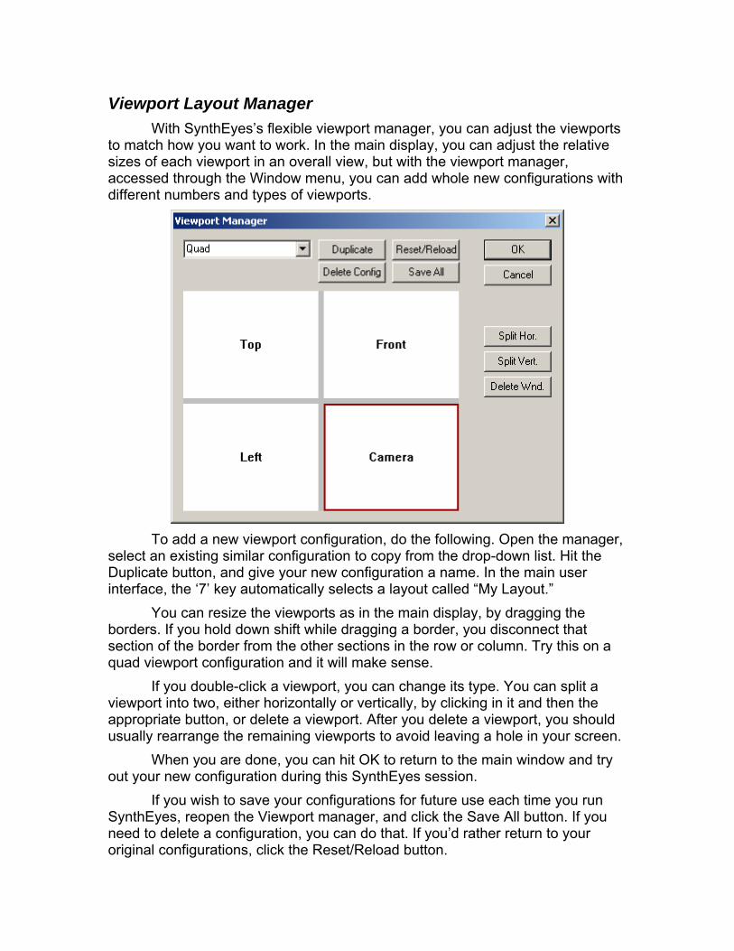
Viewport Layout Manager With SynthEyes’s flexible viewport manager, you can adjust the viewports
to match how you want to work. In the main display, you can adjust the relative sizes of each viewport in an overall view, but with the viewport manager, accessed through the Window menu, you can add whole new configurations with different numbers and types of viewports.
To add a new viewport configuration, do the following. Open the manager,
select an existing similar configuration to copy from the drop-down list. Hit the Duplicate button, and give your new configuration a name. In the main user interface, the ‘7’ key automatically selects a layout called “My Layout.”
You can resize the viewports as in the main display, by dragging the borders. If you hold down shift while dragging a border, you disconnect that section of the border from the other sections in the row or column. Try this on a quad viewport configuration and it will make sense.
If you double-click a viewport, you can change its type. You can split a viewport into two, either horizontally or vertically, by clicking in it and then the appropriate button, or delete a viewport. After you delete a viewport, you should usually rearrange the remaining viewports to avoid leaving a hole in your screen.
When you are done, you can hit OK to return to the main window and try out your new configuration during this SynthEyes session.
If you wish to save your configurations for future use each time you run SynthEyes, reopen the Viewport manager, and click the Save All button. If you need to delete a configuration, you can do that. If you’d rather return to your original configurations, click the Reset/Reload button.
Window Viewport Reference Most windows use the middle mouse button—pushing on the scroll
wheel—to pan. This can be difficult on trackballs or on Mac OSX with Microsoft’s Intellipoint mouse driver installed. There is a preferences setting, No middle-mouse button, that you can enable to use ALT/Command-Left-drag to pan instead. When this option is selected, the ALT/Command-Left-click combination, which links trackers together, is selected using ALT/Command-Right-click instead.
If you are using a tablet, you must turn off the Enable cursor wrap checkbox on the preferences panel.
Timing Bar Green triangle: start of replay loop. Left-drag Red triangle: end of replay loop. Left-drag. Left Mouse: Click or drag the current frame. Drag the start and end of the replay
loop. Shift-drag to change the overall starting or ending frame. Control-shift-drag to change the end frame, even past the end of the shot (useful when the shot is no longer available).
Middle Mouse: Drag to pan the time bar left and right. Middle Scroll: Scroll the current time. Right Mouse: Horizontal drag to pan time bar, vertical drag to zoom time bar. Or,
right click cancels an ongoing left or middle-mouse operation.
Camera Window The camera view can be floated with the Window/Floating camera menu
item. Left Mouse: Click to select and drag a tracker, or create a tracker if the Tracker
panel’s create button is lit. Shift-click to include or exclude a tracker from the existing selection set. Drag to lasso 2-D trackers, control-drag to lasso both the 2-D trackers and any 3-D points. ALT-Left-Click (Mac: Command-Left-Click) to link to a tracker, when the Tracker 3-D panel is displayed. Click the marker for a tracker on a different object, to switch to that object. Drag a Lens panel alignment line. Click on nothing to clear the selection set. If a single tracker is selected, and the Z or apostrophe/double-quote key is pressed, pushing the left mouse button will place the tracker at the mouse location (and allow it to be dragged to be fine-tuned). Or, drag a tracker’s size or search region handles.
Middle Mouse Scroll: Zoom in and out about the cursor. (See mouse preferences discussion above.)
Right Mouse: Drag vertically to zoom. Or, cancel a left or middle button action in progress.
Tracker Interior View (on the Tracker Control Panel) Left Mouse: Drag the tracker location.

Middle Scroll: Advance the current frame, tracking as you go. Right Mouse: Add or remove a position key at the current frame. Or, cancel a
drag in progress.
3-D Viewport Left Mouse: Click and Drag repeatedly to create an object, when the 3-D Panel’s
Create button is lit. ALT-Left-Click (Mac: Command-Left-Click) to link to a tracker, when the Tracker 3-D panel is displayed. Drag a lasso to select multiple trackers. Or, move, rotate, or scale an object, depending on the tool last selected on the 3-D Panel.
Middle Mouse: Drag to pan the viewport. (See mouse preferences discussion above.)
Middle Scroll: Zoom the viewport. Right Mouse: Drag vertically to zoom the viewport. Or, cancel an ongoing left or
middle-mouse operation.
Lifetimes Tracker List Left Mouse: Click to select a tracker. Shift-drag to add trackers to the selection
set. Control-click to invert a tracker’s selection status. Left Double-Click: On the Lock traffic light, flips the status of all selected
trackers. Middle Mouse: Vertical pan. Middle Scroll: Advance the current frame. Right Mouse: Cancel an ongoing left or middle-mouse operation.
Lifetimes Viewport Left Mouse: Drag the current time. Click to select a tracker. Shift-drag to add
trackers to the selection set. Control-click to invert a tracker’s selection status. ALT-drag to delete a block of keys on multiple trackers. If ALT-drag does not seem to work, remember to unlock the trackers first. With one tracker selected, double-click to repair a given frame, or shift-double-click if the tracker is locked.
Middle Mouse: Pan the display. Middle Scroll: Change the current frame. Right Mouse: Pan the display horizontally, or zoom with vertical motion. Or,
cancel an in-progress left or middle mouse operation.
Constrained Points Viewport Left Mouse: Click to select a tracker. Shift-drag to add trackers to the selection
set. Control-click to invert a tracker’s selection status. Middle Mouse: Vertical pan. Middle Scroll: Advance the current frame. Right Mouse: Cancel an ongoing left or middle-mouse operation.
Tracker Graph Left Mouse: Drag the current time. When several trackers are initially selected,
drag around to select one of them at a time: useful for picking the one noisy tracker out of a whole collection of good ones. Or, use the left and right arrow keys to step through the trackers. Drag the Velocity or Error on-screen scaling widgets (the 3-D error curves appear only after you have solved the scene). Double-click a frame with one tracker selected to use a repair strategy to correct glitches.
Middle Mouse: Pan the display. Middle Scroll: Change the current frame. Right Mouse: Pan the display horizontally, or zoom with vertical motion. Or,
cancel an in-progress left or middle mouse operation.
Object Graph Left Mouse: Drag the current time. Use the Page Up and Page Down keys to
step through the objects. Drag the Position or Rotation Velocity on-screen scaling.
Middle Mouse: Pan the display. Middle Scroll: Change the current frame. Right Mouse: Pan the display horizontally, or zoom with vertical motion. Or,
cancel an in-progress left or middle mouse operation.

Perspective Window Reference The perspective window defines quite a few different mouse modes, which
are selected by right-clicking in the perspective window. The menu modes and mouse modes are described below.
The perspective window has four entries in the viewport manager: Perspective, Perspective B, Perspective C, and Perspective D. The status of each of these flavors is maintained separately, so that you can put a perspective window in several different viewport configurations and have it maintain its view, and you can up to four different versions each preserving its own different view.
There is a basic mouse handler (‘Navigate’) operating all the time in the perspective window. You can always left-drag a handle of a mesh object to move it, or control-left-drag it to rotate around that handle. If you left-click a tracker, you can select it, shift-select to add it to the selected trackers, add it to a ray for a light, or ALT-click it to set it as the target of a selected tracker. While you are dragging as part of a mouse operation, you can right-click to cancel it.
The middle mouse button navigates in 3-D. Middle-drag pans the camera, ALT-middle-drag orbits, Control-ALT trucks it. Control-middle makes the camera look around in different directions (tripod-style pan and tilt). Doing any of the above with the shift key down slows the motion for increased accuracy. The camera will orbit around selected vertices or an object, if available.
The middle-mouse scroll wheel moves forward and back through time if the view is locked to the camera (shift-scroll zooms the time bar), and changes the camera zoom (field of view) when the camera is not locked.
The N key will switch to Navigate mode from any other mode. If you hold down the Z key or apostrophe/double-quote when you click the
left mouse button in any mode, the perspective window will switch temporarily to the Navigate mode, allowing you to use the left button to navigate. The original mode will be restored when your release the mouse button.
Right-click Menu Items
No Change. Does nothing, makes it easier to take a quick look at the menu. Lock to Current Camera. The perspective window is locked to look through the
camera selected in the overall SynthEyes user interface (ie appearing the camera view window). The camera’s imagery appears as the background for the perspective view. You can no longer move the perspective view around. If already locked, the camera is unlocked: the background disappears, the camera is made upright (roll=0), and the view can be changed. Keyboard: ‘L’ key.
View. Submenu, see details below.
Navigate. When this mode is selected, the mouse navigation actions are activated by the left mouse button, not just the middle mouse. Keyboard: ‘N’ key.
Place. Slide a tracker’s seed position, an extra helper point, or a mesh around on the surface of meshes. Use to place seed points on reference head meshes, for example. With control key pushed, position snaps only onto vertices, not anywhere on mesh.
Field of View. Adjust the perspective view’s field of view (zoom). Normally you should drive forward to get a closer view.
Lasso Trackers. Lasso-select trackers. Shift-select trackers to add to the selection, and control-select to complement their selection status.
Lasso Mesh. Lasso-select vertices of the current edit mesh. Or click directly on the vertices.
Add Vertices. Add vertices to the edit mesh, placing them on the current grid. Use the shift key to move up or down normal to the grid. If control is down, build a facet out of this vertex and the two previously added.
Move Vertices. Move the selected vertices around parallel to the current grid, or if shift is down, perpendicular to it. Use control to slow the movement. If clicking on a vertex, shift will add it to the selection set, control-shift will remove it from the selection set.
Set as Edit Mesh. Open the currently-selected mesh for editing, exposing its vertices. If no object is selected, any edit mesh is closed. Keyboard: ‘M’ key.
Create Mesh Object. Creates a mesh object on the current grid. The type of object created is controlled by the 3-D control panel, as it is for the other viewports.
Creation Object. Submenu selecting the object to be created. Mesh Operations. Submenu for mesh operations. See below. Texturing. Submenu for texture mapping. See below. Grid. Submenu for the grid. See below. Preview Movie. Renders the perspective view for the entire frame range to
create a movie for playback. See the preview control panel referece below.
View Submenu Local coordinate handles. The handles on the meshes can be oriented along
either the global coordinate axes, or the axes of the mesh itself, this menu check item controls which is displayed.
Whole path. Moves a camera or object and its trackers simultaneously. See 3-D Control Panel.
Lock Selection. Prevents the selection from being changed when clicking in the viewport, good for dense work areas.
Reset FOV. Reset the field of view to 45 degrees. Perspective View Settings. Brings up the Scene Settings dialog, which has
many sizing controls for the perspective view: clip planes, tracker size, etc. Additional “show” controls in this menu can be found on the view menu.
Mesh Operations Submenu Convert to Mesh. Converts the selected trackers, or all of them, and adds them
to the edit mesh as vertices, with no facets. If there is no current edit mesh, a new one is created.
Triangulate. Adds facets to the selected vertices of the edit mesh. Position the view to observe the collection from above, not from the side, before triangulating.
Remove and Repair. The selected vertices are removed from the mesh, and the resulting hole triangulated to paper it over without those vertices.
Subdivide Facets. Selected facets have a new vertex added at their center, and each facet replaced with three new ones surrounding the new vertex.
Subdivide Edges. The selected edges are bisected by new vertices, and selected facets replaced with four new ones.
Delete selected faces. Selected facets are deleted from the edit mesh. Vertices are left in place for later deletion or so new facets can be added.
Delete unused vertices. Deletes any vertices of the edit mesh that are not part of any facet.
Texturing Submenu Frozen Front Projection. The current frame is frozen to form a texture map for
every other frame in the shot. The object disappears in this frame; in other frames you can see geometric distortion as the mesh (with this image applied) is viewed from other directions.
Rolling Front Projection. The edit mesh will have the shot applied to it as a texture, but the image applied will always be the current one.
Remove Front Projection. Texture-mapping front projection is removed from the edit mesh.
Clear Texture Coords. Any UV texture coordinates are cleared from the edit mesh, whether they are due to front projection or importing.
Create Smooth Normals. Creates a normal vector at each vertex of the edit mesh, averaging over the attached facets. The smooth normals are used to provide a smooth perspective display of the mesh.
Clear Normals. The per-vertex normals are cleared, so face normals will be used subsequently.
Grid Submenu Show Grid. Toggle. Turns grid display on and off in this perspective window.
Keyboard: ‘G’ key. Move Grid. Mouse mode. Left-dragging will slide the grid along its normal mode,
for example, allowing you to raise or lower a floor grid. Floor Grid, Back Grid, Left Side Grid, Ceiling Grid, Front Grid, Right Side
Grid. Puts the grid on the corresponding wall of a virtual room (stage), normally viewed from the front. The grids are described this way so that they are not affected by the current coordinate system selection.
To Facet/Verts/Trkrs. Aligns the grid using an edit-mesh facet, 1 to 3 edit-mesh vertices, if a mesh is open for editing, or 1 to 3 trackers otherwise. This is

a very important operation for detail work. With 3 points selected, the grid is the plane that contains those 3 points, centered between them, aligned to preserve the global upwards direction. With 2 points selected, the current grid is spun to make its “sideways” axis aligned with the two points (in Z up mode, the X axis is made parallel to the two points). With 1 point selected, the grid is moved to put its center at that point. Often it will be useful to use this item 3 times in a row, first with 3 then with 2 and finally 1 vertex or tracker selected.
Return to custom grid. Use a custom grid set up earlier by To Facet/Verts/Trkrs. The custom grid is shared between perspective windows, so you can define it in one window, and use it in one or more others as well.
Object-Mode Grids. Submenu. Contains forward-facing object, backward-facing object, etc, selections. Requires that the SynthEyes main user interface be set to a moving object, not a camera. Each of these modes creates a grid through the origin of the object’s coordinate system, facing in the direction indicated. An upward-facing grid means that creating an object on it will go on the plus-object-Z side in Z-up mode. Downward-facing will go in nearly the same spot, but on the flip side.
Preview Movie Control Panel
File name/… Select the output file name to which the movie should be written.
Either a Quicktime movie, OpenEXR, or BMP file can be produced. For image sequences, the file name given is that of the first frame; this is your chance to specify how many digits are needed and the starting value, for example, prev1.bmp or prevu0030.exr.
Compression Settings. Set the compression settings for Quicktime.

Show All Viewport Items. Includes all the trackers, handles, etc, shown in the viewport as part of the preview movie.
Show Grid. Controls whether or not the grid is shown in the movie. Square-Pixel Output. When off, the preview movie will be produced at the same
resolution as the input shot. When on, the resolution will be adjusted so that the pixel aspect ratio is 1.0, for undistorted display on computer monitors by standard playback programs.
RGB Included. Must be on to see the normal RGB images. See below. Depth Included. Output a monochrome depth map. See below. Anti-aliasing. Select None, Low, Medium, High to determine output image
quality. The allowable output channels depend on the output format. Quicktime
accepts only RGB. Bitmap can take RGB or depth, but not both at once. OpenEXR can have either or both.

Control Panel Reference SynthEyes has the following control panels:
• Summary Panel • Feature Control Panel • Rotoscope Control Panel • Tracking Control Panel. • Coordinate System Control Panel. • Lens Control Panel. • Solver Control Panel. • 3-D Control Panel. • Lighting Control Panel. • Flex/Curve Control Panel.
Select via the control panel selection portion of the main toolbar.
The Lifetimes Tracker List appears in the control panel, but is largely
associated with the Lifetimes viewport. Four additional panels are described below:
• Image Preparation • Advanced Features • Finalize Trackers Dialog • Add Many Trackers Dialog • Coalesce Nearby Trackers Dialog • Green-screen control • Curve tracking control
The shot-setup dialog is described in the section Opening the Shot.
Spinners SynthEyes uses spinners, the stacked triangles on the right of the
following graphic ( ), to permit easy adjustment of numeric fields on the control panels. The spinner control provides the following features:
• Click either triangle to increase or decrease the value in steps, • Drag within the control to smoothly increase and decrease the value, • Turns red on key frames, • Right-click to remove a key, or if none, to reset to a predefined value, • Shift-drag or -click to change the value much more rapidly, • Control-drag or -click to change the value slowly for fine-tuning.
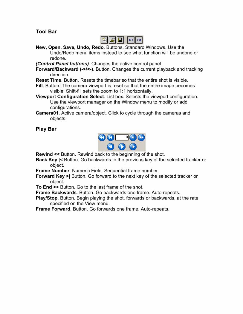
Tool Bar
New, Open, Save, Undo, Redo. Buttons. Standard Windows. Use the
Undo/Redo menu items instead to see what function will be undone or redone.
(Control Panel buttons). Changes the active control panel. Forward/Backward (->/<-). Button. Changes the current playback and tracking
direction. Reset Time. Button. Resets the timebar so that the entire shot is visible. Fill. Button. The camera viewport is reset so that the entire image becomes
visible. Shift-fill sets the zoom to 1:1 horizontally. Viewport Configuration Select. List box. Selects the viewport configuration.
Use the viewport manager on the Window menu to modify or add configurations.
Camera01. Active camera/object. Click to cycle through the cameras and objects.
Play Bar
Rewind << Button. Rewind back to the beginning of the shot. Back Key |< Button. Go backwards to the previous key of the selected tracker or
object. Frame Number. Numeric Field. Sequential frame number. Forward Key >| Button. Go forward to the next key of the selected tracker or
object. To End >> Button. Go to the last frame of the shot. Frame Backwards. Button. Go backwards one frame. Auto-repeats. Play/Stop. Button. Begin playing the shot, forwards or backwards, at the rate
specified on the View menu. Frame Forward. Button. Go forwards one frame. Auto-repeats.

Summary Panel
Motion Profile. Select one of several profiles reflecting the kinds of motion the
image makes. Use Crash Pan for when the camera spins quickly, for example, to be able to keep up. Or use Gentle Motion for faster processing when the camera/image moves only slightly each frame.
Full Automatic. Use this after a shot is open, to run the match-move process. See also Submit for Batch.
Coords. Initiates a mode where 3 trackers can be clicked to define a coordinate system. After the third, you will have the opportunity to re-solve the scene to apply the new settings. Same as *3 on the Coordinate System panel.
Master Solution Reset (X). Clear any existing solution: points and object paths. Zoom Lens. Check this box if the camera zooms. On Tripod. Check this box if the camera was on a tripod. Run Auto-tracker. Runs the automatic tracking stage, then stops. Solve. Runs the solver. Not solved. This field will show the overall scene error, in horizontal pixels, after
solving. Green Screen. Brings up the green-screen control dialog.

Feature Control Panel
Motion Profile. Select one of several profiles reflecting the kinds of motion the
image makes. Use Crash Pan for when the camera spins quickly, for example, to be able to keep up. Or use Gentle Motion for faster processing when the camera/image moves only slightly each frame.
Clear all blips. Clears the blips from all frames. Use to save disk space after blips have been peeled to trackers.
Blips this frame. Push button. Calculates features (blips) for this frame. Blips playback range. Push button. Calculates features for the playback range
of frames. Blips all frames. Push button. Calculates features for the entire shot. Displays
the frame number while calculating. Once started, can’t be interrupted! Delete. X Button. Clears the skip frame channel from this frame to the end of the
shot, or the entire shot if Shift is down when clicked. Skip Frame. Checkbox. When set, this frame will be ignored during automatic
tracking and solving. Use (sparingly) for occasional bad frames during explosions or actors blocking the entire view. Camera paths are spline interpolated on skipped frames.
Advanced. Push button. Brings up a panel with additional control parameters. Link frames. Push button. Blips from each frame in the shot are linked to those
on the prior frame (depending on tracking direction). Useful after changes in splines or alpha channels.
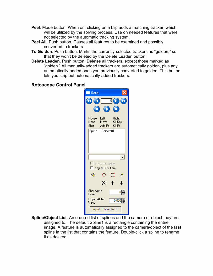
Peel. Mode button. When on, clicking on a blip adds a matching tracker, which will be utilized by the solving process. Use on needed features that were not selected by the automatic tracking system.
Peel All. Push button. Causes all features to be examined and possibly converted to trackers.
To Golden. Push button. Marks the currently-selected trackers as “golden,” so that they won’t be deleted by the Delete Leaden button.
Delete Leaden. Push button. Deletes all trackers, except those marked as “golden.” All manually-added trackers are automatically golden, plus any automatically-added ones you previously converted to golden. This button lets you strip out automatically-added trackers.
Rotoscope Control Panel
Spline/Object List. An ordered list of splines and the camera or object they are
assigned to. The default Spline1 is a rectangle containing the entire image. A feature is automatically assigned to the camera/object of the last spline in the list that contains the feature. Double-click a spline to rename it as desired.

Camera/Object Selector. Drop-down list. Use to set the camera/object of the spline selected in the Spline/Object List. You can also select Garbage to set the spline as a garbage matte.
Show this spline. Checkbox. Turn on and off to show or hide the selected spline. Also see the View/Only Selected Splines menu item.
Key all CPs if any. Checkbox. When on, moving any control point will place a key on all control points for that frame. This can help make keyframing more predictable for some splines.
Enable. “Stoplight” button. Animatable spline enable. Create Circle. Lets you drag out circular splines. Create Box. Lets you drag out rectangular splines. Magic Wand. Lets you click out arbitrarily-shaped splines with many control
points. Delete. Deletes the currently-selected spline. Move Up. Push button. Moves the selected spline up in the Spline/Object List,
making it lower priority. Move Down. Push button. Moves the selected spline down in the Spline/Object
List, making it higher priority. Shot Alpha Levels. Integer spinner. Sets the number of levels in the alpha
channel for the shot. For example, select 2 for an alpha channel containing only 0 or 1(255), which you can then assign to a camera or moving object.
Object Alpha Level. Spinner. Sets the alpha level assigned to the current camera or object. For example, with 2 alpha levels, you might assign level 0 to the camera, and 1 to a moving object. The alpha channel is used to assign a feature only if it is not contained in any of the splines.
Import Tracker to CP. Button. When activated, select a tracker then click on a spline control point. The tracker’s path will be imported as keys onto the control point.
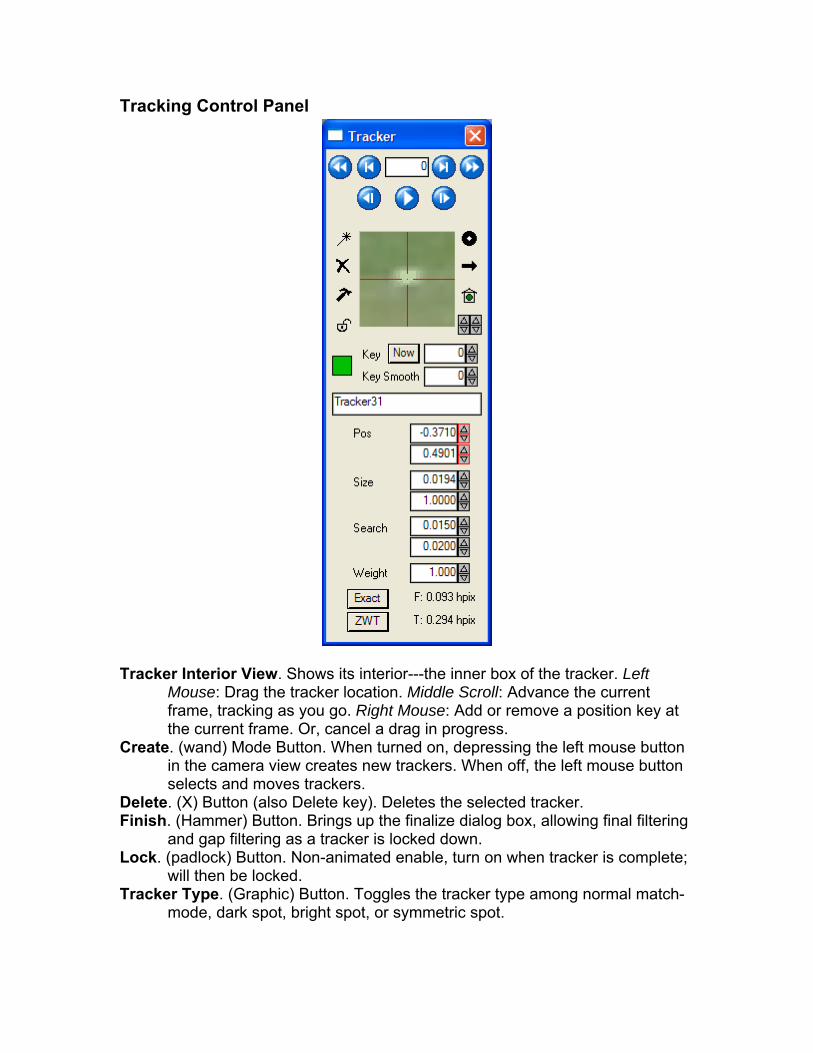
Tracking Control Panel
Tracker Interior View. Shows its interior---the inner box of the tracker. Left
Mouse: Drag the tracker location. Middle Scroll: Advance the current frame, tracking as you go. Right Mouse: Add or remove a position key at the current frame. Or, cancel a drag in progress.
Create. (wand) Mode Button. When turned on, depressing the left mouse button in the camera view creates new trackers. When off, the left mouse button selects and moves trackers.
Delete. (X) Button (also Delete key). Deletes the selected tracker. Finish. (Hammer) Button. Brings up the finalize dialog box, allowing final filtering
and gap filtering as a tracker is locked down. Lock. (padlock) Button. Non-animated enable, turn on when tracker is complete;
will then be locked. Tracker Type. (Graphic) Button. Toggles the tracker type among normal match-
mode, dark spot, bright spot, or symmetric spot.

Direction. (Arrow) Button. Configures the tracker for backwards tracking: it will only track when playing or stepping backwards.
Enable. (Stoplight) Button. Animated control turns tracker on or off. Turn off when tracker gets blocked by some thing, turn back on when it becomes visible again.
Contrast. Number-less spinner. Enhances contrast in the Tracker Interior View window.
Bright. Number-less spinner. Turns up the Tracker Interior View brightness. Color. Rectangular swatch. Sets the display color of the tracker for the camera,
perspective, and 3-D views. Now. Button. Adds a tracker position key at the present location and frame.
Right-click to remove a position key. Shift-right-click to truncate, removing all following keys.
Key. Spinner tells SynthEyes to automatically add a key after this many frames, to keep the tracker on track.
Key Smooth. Spinner. Tracker’s path will be smoothed for this many frames before each key, so there is no glitch due to re-setting a key.
Name. Edit field. Adjust the tracker’s name to describe what it’s tracking. Pos. H and V spinners. Tracker’s horizontal and vertical position, from –1 to +1 Size. Size and aspect spinners. Size and aspect ratio (horizontal divided by
vertical size) of the interior portion of the tracker. Search. H and V spinners. Horizontal and vertical size of the region (excluding
the actual interior) that SynthEyes will search for the tracker around its position in the preceding frame. Preceding implies lower-numbered for forward tracking, higher-numbered for backward tracking.
Weight. Spinner. Defaults to 1.0. Multiplier that helps determine the weight given to the 2-D data for each frame from this tracker. Higher values cause a closer match, lower values allow a sloppier match. WARNING: This control is for experts and should be used judiciously and infrequently. It is easy to use it to mathematically destabilize the solving process, so that you will not get a valid solution at all. Keep near 1. Also see ZWTs below.
Exact. For use after a scene has already been solved: set the tracker’s 2-D position to the exact re-projected location of the tracker’s 3-D position. A quick fix for spurious or missing data points, do not overuse. See the section on filtering and filling gaps. Note: applied to a zero-weighted-tracker, error will not become zero because
F: n.nnn hpix. (display field, right of Exact button) Shows the distance, in horizontal pixels, between the 2-D tracker location and the re-projected 3-D tracker location. Valid only if the tracker has been solved.
ZWT. When on, the tracker’s weight is internally set to zero—it is a zero-weighted-tracker (ZWT), which does not affect the camera or object’s path at all. As a consequence, its 3-D position can be continually calculated as you update the 2-D track or change the camera or object path, or field of view. The Weight spinner of a ZWT will be disabled, because the weight is internally forced to zero and special processing engaged. The grayed-out

displayed value will be the original weight, which will be restored if ZWT mode is turned off.
T: n.nnn hpix. (display field, right of ZWT button) Shows the total error, in horizontal pixels, for the solved tracker. This is the same error as from the Coordinate System panel. It updates dynamically during tracking of a zero-weighted tracker.
Coordinate System Control Panel
Tracker Name. Edit. Shows the name of selected tracker, or change it to
describe what it is tracking. Camera/Object. Drop-down list. Shows what object or camera the tracker is
associated with; change it to move the tracker to a different object or camera on the same shot. Entries beginning with asterisk(*) are on a different shot with the same aspect and length; trackers may be moved there, though this may adversely affect constraints, lights, etc.
*3. Button. Starts and controls three-point coordinate setup mode. Click it once to begin, then click on origin, on-axis, and on-plane trackers in the camera view, 3-D viewports, or perspective window. The button will sequence

through Or, LR, FB, and Pl to indicate which tracker should be clicked next. Click this button to skip from LR (left/right) to FB (front/back), or to skip setting other trackers. After the third tracker, you will have the opportunity to re-solve the scene to apply the new settings.
Seed & Lock. X, Y, Z spinners. An initial position used as a guess at the start of solving (if seed checkbox on), and/or a position to which the tracker is locked, depending on the Lock Type list.
Seed. Mode button. When on, the X/Y/Z location will be used to help estimate camera/object position at the start of solving, if Points seeding mode is selected.
Peg. Mode button. If on, and the Solver panel’s Constrain checkbox is on, the tracker will be pegged exactly, as selected by the Lock Type. Otherwise, the solver may modify the constraints to minimize overall error. See documentation for details and limitations.
Far. Mode button. Turn on if the tracker is far from the camera. Example: If the camera moved 10 feet during the shot, turn on for any point 10,000 feet or more away. Far points are on the horizon, and their distance can not be estimated.
Lock Type. Drop-down list. Has no effect if Unlocked. The other settings tell SynthEyes to force one or more tracker position coordinates to 0 or the corresponding seed axis value. Use to lock the tracker to the origin, the floor, a wall, a known measured position, etc. See the section on Lock Mode Details.
Target Point. Button. Use to set up links between trackers. Select one tracker, click the Target Point button to select the target tracker by name. Or, ALT-click (Mac: Command-Left-Click) the target tracker in the camera view or 3-D viewport. If the trackers are on the same camera/object, the Distance spinner activates to control the desired distance between the trackers. You can also lock one or more of their coordinates to be identical, forcing them parallel to the same axis or plane. If the trackers are on different camera/objects, you have created a link: the two trackers will be forced to the same location during solving. If two trackers track the same feature, but one tracker is on a DV shot, the other on digital camera stills, use the link to make them have the same location. Right-click to remove an existing target tracker.
Dist. Spinner. Sets the desired distance between two trackers on the same object.
Solved. X, Y, Z numbers. After solving, the final tracker location. Error. Number. After solving, the root-mean-square error between this tracker’s
predicted and actual positions. If the error exceeds 1 pixel, look for tracking problems using the Tracker Graph window.
Set Seed. Button. After solving, sets the computed location up as the seed location for later solver passes using Points mode.
All. Button. Sets up all solved trackers as seeds for subsequent passes. Exportable. Checkbox. Uncheck this box to tell savvy export scripts not to export
this tracker. For example, exporting to a compositor, you may want only a

half dozen of a hundred or two automatically-generated trackers to be exported and create a new layer in the compositor. Non-exportable points are shown in a different color, somewhat closer to that of the background.
Lens Control Panel
Field of View. Spinner. Field of view, in degrees, on this frame. Focal Length. Spinner. Focal length, computed using the current Back Plate
Width on Scene Settings. Provided for illustration only. Add/Remove Key. Button. Add or remove a key to the field of view (focal length)
track at this frame. Known. Radio Button. Field of view is already known (typically from an earlier
run) and is taken from the field of view seed track. May be fixed or zooming.
Fixed, Unknown. Radio Button. Field of view is unknown, but did not zoom during the shot.
Zooming, Unknown. Radio Button. Field of view zoomed during shot. Lens Distortion. Spinner. Show/change the lens distortion coefficient. Calculate Distortion. Checkbox. When checked, SynthEyes will calculate the
lens distortion coefficient. You should have plenty of well-distributed trackers in your shot.

Add Line. Checkbox. Adds an alignment line to the image that you can line up with a straight line in the image, adjust the lens distortion to match, and/or use it for tripod or lock-off scene alignment.
Kill Line. Checkbox. Removes the selected alignment line (the delete key also does this). Control-click to delete all the alignment lines at once.
Axis Type. Drop-down list. Not oriented, if the line is only there for lens distortion determination, parallel to one of the three axes, along one of the three (XYZ) axes, or along one of the three axes, with the length specified by the spinner. Configures the line for alignment.
<->. Button. Swaps an alignment line end for end. The direction of a line is significant and displayed only for on-axis lines.
Length. Spinner. Sets the length of the line to control overall scene sizing during alignment. Only a single line, which must be on-axis, can have a length.
At nnnf. Button. Shows (not set) if no alignment lines have been configured. This button shows the (single) frame on which alignment lines have been defined and alignment will take place; clicking the button takes you to this frame. Set each time you change an alignment line, or right-click the button to set it to the current frame.
Align! Button. Aligns the scene to match the alignment lines defined—on the frame given by the At… button. Other frames are adjusted correspondingly. To sequence through all the possible solutions, control-click this button.
Solver Control Panel

Go! Button. Starts the solving process, after tracking is complete. Master Reset. Button. Resets all cameras/objects and the trackers on them,
though all Disabled camera/objects are left untouched. Seeding Method. Upper drop-down list controlling the way the solver begins its
solving process, chosen from the following methods: Auto. List Item. Selects the automatic seeding(initial estimation) process,
for a camera that physically moves during the shot. Refine. List item. Resumes a previous solving cycle, generally after
changes in trackers or coordinate systems. Tripod. List Item. Use when the camera pans, tilts, and zooms, but does
not move. Refine Tripod. List item. Resumes a previous solving cycle, but indicates
that the camera was mounted on a tripod. Indirect. List Item. Use for camera/objects which will be seeded from links
to other camera/objects, for example, a DV shot indirectly seeded from digital camera stills.
Individual. List Item. Use for motion capture. The object’s trackers are solved individually to determine their path, using the same feature on other “Individual” objects; the corresponding trackers are linked in one direction.
Points. List Item. Seed from seed points, set up from the 3-D trackers panel. Use with on-set measurement data, or after Set All on the Coordinate Panel. You should still configure coordinate system constraints with this mode: some hard locks and/or distance constraints.
Path. List Item. Uses the camera/object’s seed path as a seed, for example, from a previous solution or a motion-controlled camera.
Disabled. List Item. This camera/object is disabled and will not be solved for.
Directional Hint. Second drop-down list. Gives a hint to speed the initial estimation process, or to help select the correct solution, or to specify camera timing for “Individual” objects. Chosen from the following for Automatic objects: Automatic. List Item. In automatic seeding mode, SynthEyes can be
given a hint as to the general direction of motion of the camera to save time. With the automatic button checked, it doesn’t need such a hint.
Left. List Item. The camera moved generally to its left. Right. List Item. The camera moved generally to its right. Up. List Item. The camera moved generally upwards. Down. List Item. The camera moved generally downwards. Push In. List Item. The camera moved forward (different than zooming
in!). Pull Back. List Item. The camera moved backwards (different than
zooming out!).
Camera Timing Setting. The following items are displayed when “Individual” is selected as the object solving mode. They actually apply to the entire shot, not just the particular object. Sync Locked. List Item. The shot is either the main timing reference, or is
locked to it (ie, gen-locked video camera). Crystal Sync. List Item. The camera has a crystal-controlled frame rate
(ie a video camera at exactly 29.97 Hz), but it may be up to a frame out of synchronization because it is not actually locked.
Loosely Synced. List item. The camera’s frame rate may vary somewhat from nominal, and will be determined relative the reference. Notably, a mechanical film camera.
Slow but sure. Checkbox. When checked, SynthEyes looks especially hard (and longer) for the best initial solution.
Begin. Spinner and checkbox. Numeric display shows an initial frame used by SynthEyes during automatic estimation. With the checkbox checked, you can override the begin frame solution. Either manually or automatically, the camera should have panned or tilted only about 30 degrees. If the camera does something wild between the automatically-selected frames, or if their data is particularly unreliable for some reason, you can manually select the frames instead. The selected frame will be selected as you adjust this, and the number of frames in common shown on the status line.
End. Spinner and checkbox. Numeric display shows a final frame used by SynthEyes during automatic estimation. With the checkbox checked, you can override the end frame solution.
World size. Spinner. Rough estimate of the size of the scene, including the trackers and motion of the camera.
Transition Frms. Spinner. When trackers first become usable or are about to become unusable, SynthEyes gradually reduces their impact on the solution, to maintain an undetectable transition. The value specifies how many frames to spread the transition over.
Filter Frms. Spinner. Controls post-solving path filtering. If this control is set to 3, say, then each frame’s camera position is a (weighted) average of its position within 3 frames earlier and 3 frames later in the sequence. A larger number creates a smoother path.
Weight. Spinner. Defaults to 1.0. Multiplier that helps determine the weight given to the data for each frame from this object’s trackers. Lower values allow a sloppier match, higher values cause a closer match, for example, on a high-resolution calibration sequence consisting of only a few frames. WARNING: This control is for experts and should be used judiciously and infrequently. It is easy to use it to mathematically destabilize the solving process, so that you will not get a valid solution at all. Keep near 1.
Error. Number display. Root-mean-square error, in horizontal pixels, of all trackers associated with this object or tracker.
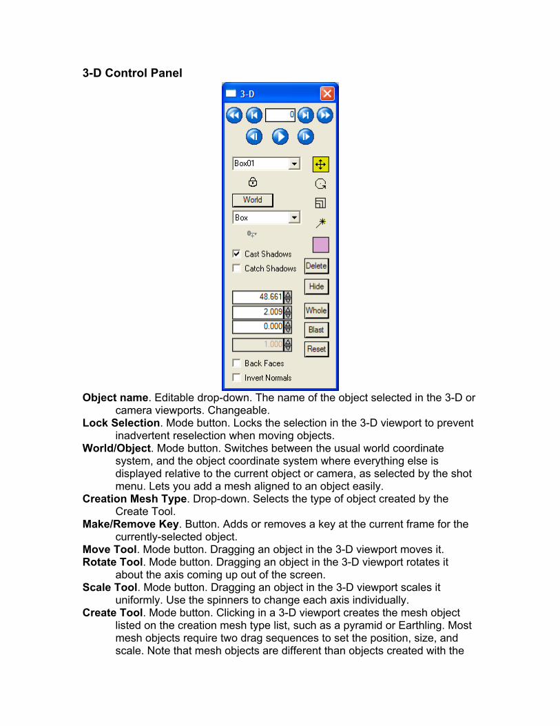
3-D Control Panel
Object name. Editable drop-down. The name of the object selected in the 3-D or
camera viewports. Changeable. Lock Selection. Mode button. Locks the selection in the 3-D viewport to prevent
inadvertent reselection when moving objects. World/Object. Mode button. Switches between the usual world coordinate
system, and the object coordinate system where everything else is displayed relative to the current object or camera, as selected by the shot menu. Lets you add a mesh aligned to an object easily.
Creation Mesh Type. Drop-down. Selects the type of object created by the Create Tool.
Make/Remove Key. Button. Adds or removes a key at the current frame for the currently-selected object.
Move Tool. Mode button. Dragging an object in the 3-D viewport moves it. Rotate Tool. Mode button. Dragging an object in the 3-D viewport rotates it
about the axis coming up out of the screen. Scale Tool. Mode button. Dragging an object in the 3-D viewport scales it
uniformly. Use the spinners to change each axis individually. Create Tool. Mode button. Clicking in a 3-D viewport creates the mesh object
listed on the creation mesh type list, such as a pyramid or Earthling. Most mesh objects require two drag sequences to set the position, size, and scale. Note that mesh objects are different than objects created with the
Shot Menu’s Add Moving Object button. Moving objects can have trackers associated with them, but are themselves null objects. Mesh objects have a mesh, but no trackers. Often you will create a moving object and its trackers, then add a mesh object(s) to it after solving to check the track.
Object color. Color Swatch. Object color, click to change. Delete. Button. Deletes the selected object. Show/Hide. Button. Show or hide the selected mesh object. X/Y/Z Values. Spinners. Display X, Y, or Z position, rotation or scale values,
depending on the currently-selected tool. Size. Spinner. This is an overall size spinner, use it when the Scale Tool is
selected to change all three axis scales in lockstep. Whole. Button. When moving a solved object, normally it moves only for the
current frame, allowing you to tweak particular frames. If you turn on Whole, moving the object moves the entire path, so you can adjust your coordinate system without using locks. If you do this, you should set up some locks subsequently and switch to Point or Path seeding, or you will have to readjust the path again if you re-solve. Hint: Whole mode has some rules to decide whether or not to affect meshes. To force it to include all meshes in the action, turn on Whole affects meshes on the 3-D viewport and perspective window’s right-click menu.
Blast. Button. Writes the entire solved history onto the object’s seed path, so it can be used for path seeding mode.
Reset. Button. Clears the object’s solved path, exposing the seed path.
Lighting Control Panel

New Light. Button. Click to create a new light in the scene. Delete Light. Button. Delete the light in the selected-light drop-down list. Selected Light. Drop-down list. Shows the select light, and lets you change its
name, or select a different one. Far-away light. When checked, light is a distant, directional, light. When off, light
is a nearby spotlight or omnidirectional(point) light. Compute over frames: This, All, Lock. In the (normal) This mode, the light’s
position is computed for each frame independently. In the All or Lock mode, the light’s position is averaged over all the frames in the sequence. In the All mode, this calculation is performed repeatedly for “live updates.” In the Lock mode, the calculation occurs only when clicking the Lock button.
New Ray. Button. Creates a new ray on the selected light. Delete Ray. Button. Delete the selected ray. Previous Ray (<). Button. Switch to the previous lower-numbered ray on the
selected light. Ray Number. Text field. Shows something like 1/3 to indicate ray 1 of 3 for this
light. Next Ray (>). Button. Switch to the next higher ray on the selected light.
Selected Ray Source. Mode button. When lit up, click a tracker in the camera view or any 3-D
view to mark it as one point on the ray. Target. Mode button. When lit up, click a tracker in the camera view or any 3-D
view to mark it as one point on the ray. If the source and target trackers are the same, it is a reflected-highlight tracking setup, and the Target button will show “(highlight).” For highlight tracking to be functional, there must be a mesh object for the tracker to reflect from.
Distance. Spinner. When only a single ray to a nearby light is available, use this spinner to adjust the distance to the light. Leave at zero the rest of the time.

Flex/Curve Control Panel
The flex/curve control panel handles both object types, which are used to determine the 3-D position/shape of a curve in 3-D, even if it has no discernable point features. If you select a curve, the parameters of its parent flex (if any) will be shown in the flex section of the dialog. New Flex. Creates and selects a new flex. Left-click successively in a 3-D view
or the perspective view to lay down a series of control points. Right-click to end.
Delete Flex. Deletes the selected flex (even if it was a curve that was initially clicked).
Flex Name List. Lists all the flexes in the scene, allowing you to select a flex, or change its name.
Moving Object List. If the flex is parented to a moving object, it is shown here. Normally, “(world)” will be listed.
Show this 3-D flex. Controls whether the flex is seen in the viewports or not. Clear. Clears any existing 3-D solution for the flex, so that the flex’s initial seed
control points may be seen and changed. Solve. Solves for the 3-D position and shape of the flex. The control points
disappear, and the solved shape becomes visible. All. Causes all the flexes to be solved simultaneously. Pixel error. Root-mean-square (~average) error in the solved flex, in horizontal
pixels. Count. The number of points that will be solved for along the length of the flex. Stiffness. Controls the relative importance of keeping the flex stiff and straight
versus reproducing each detail in the curves. Stretch. Relative importance of (not) being stretchy. Endiness. (yes, made this up) Relative importance of exactly meeting the end-
point specification. New Curve. Begins creating a new curve—click on a series of points in the
camera view. Delete. Deletes the curve. Curve Name List. Shows the currently-selected curves name among a list of all
the curves attached to the current flex, or all the unconnected curves if this one is not connected.
Parent Flex List. Shows the parent flex of this curve, among all of the flexes. Show. Controls whether or not the curve is shown in the viewport. Enable. Animated checkbox indicating whether the curve should be enabled or
not on the current frame. For example, turn it off after the curve goes off-screen, or if the curve is occluded by something that prevents its correct position from being determined.
Key all. When on, changing one control point will add a key on all of them. Rough. Select several trackers, turn this button on, then click a curve to use the
trackers to roughly position the curve throughout the length of the shot. Truncate. Kills all the keys off the tracker from the current frame to the end of the
shot. Tune. Snaps the curve exactly onto the edge underneath it, on the current frame. All. Brings up the Curve Tracking Control dialog, which allows this curve, or all
the curves, to be tracked throughout an entire range of frames.
Image Preparation Dialog The image preparation dialog allows the incoming images from disk to be
modified before they are cached in RAM for replay and tracking. The dialog is launched either from the open-shot dialog, or from the Shot/Image Preparation menu item.

Like the main SynthEyes user interface, the image preparation dialog has
several tabs, each bringing up a different set of controls. The Stabilize tab is active above. With the left button pushed, you can review all the tabs quickly.
For more information on this panel, see the Image Preparation and Stabilization sections.
Warning: you should be sure to set up the cropping and distortion/scale values before beginning tracking or creating rotosplines. The splines and trackers do not automatically update to adapt to these changes in the underlying image structure, which can be complex. Shared Controls OK. Button. Closes the image preprocessing dialog and flushes no-longer-valid
frames the RAM buffer to make way for the new version of the shot images. You can use SynthEyes’s main undo button to undo all the effects of the Image Preprocessing dialog as a unit, or then redo them if desired.
Cancel. Button. Undoes the changes made using the image preprocessing dialog, then closes it.
Undo. Button. Undo the latest change made using the image preprocessing panel. You can not undo changes made before the panel was opened.
Redo. Button. Redo the last change undone. Final. Button. Reads either Final or Padded: the two display modes of the
viewport. The final view shows the final image coming from the image preparation subsection. The padded view shows the image after padding and lens undistortion, but before stabilization or resampling.
Both. Button. Reads either Both, Neither, or ImgPrep, indicating whether the image prep and/or main SynthEyes display window are updated simultaneously as you change the image prep controls. Neither mode

saves time if you do not need to see what you are doing. Both mode allows you to show the Padded view and Final view (in the main camera view) simultaneously.
Margin. Spinner. Creates an extra off-screen border around the image in the image prep view. Makes it easier to see and understand what the stabilizer is doing, in particular.
Show. Button. When enabled, trackers are shown in the image prep view. Image Prep View. Image display. Shows either the final image produced by the
image prep subsystem (Final mode), or the image obtained after padding the image and undistorting it (Padded mode). You can drag the Region-of-interest (ROI) and Point-of-interest (POI) around, plus you can click to select trackers, or lasso-select by dragging.
Playbar (at bottom) Preset Manager. Drop-down. Lets you create and control presets for the image
prep system, for example, different presets for the entire shot and for each moving object in the shot.
Preset Mgr. Disconnect from the current preset; further changes on the panel will not affect the preset.
New preset. Create and attach to a new preset. You will be prompted for the name of the new preset.
Reset. Resets the current preset to the initial settings, which do nothing to the image.
Rename. Prompt for a new name for the current preset. Delete. Delete the current preset. Your presets. Selecting your preset will switch to it. Any changes
you then make will affect that preset, unless you later select the Preset Mgr. item before switching to a different preset.
Rewind. Button. Go back to the beginning of the shot. Back Key. Button. Go back to the previous frame with a ROI or Levels key. Back Frame. Button. Go back one frame; with Control down, back one key; with
Shift down, back to the beginning of the shot. Auto-repeats. Frame. Spinner. The frame to be displayed in the viewport, and to set keys for.
Note that the image does not update while the spinner drags because that would require fetching all the intermediate frames from disk, which is largely what we’re trying to avoid.
Forward Frame. Button. Go forward one frame; with Control down, forward one key; with Shift down, forward to the end of the shot. Auto-repeats.
Forward Key. Button. Go forward to the next frame with a ROI or Levels key. To End. Button. Go to the end of the shot. Make Keys. Checkbox. When off, any changes to the levels or region of interest
create keys at frame zero (for when they are not animated). With the checkbox on, keys are created at the current frame.
Enable. Button (stoplight). Allows you to temporarily disable levels, color, blur, downsampling, channels, and ROI, but not padding or distortion. Use to find a lost ROI, for example. Effective only within image prep.

Rez Tab Blur. Spinner. Causes a Gaussian blur with the specified radius, typically to
minimize the effect of grain in film. Applied before down-sampling, so it can eliminate artifacts.
DownRez. Drop-down list: None, By 1/2, By 1/4. Causes the image from disk to be reduced in resolution by the specified amount, saving RAM and time for large film images, but reducing accuracy as well.
Channel. Drop-down list: RGB, Luma, R, G, B, A. Allows a luminance image to be used for tracking, or an individual channel such as red or green. Blue is usually noisy, alpha is only for spot-checking the incoming alpha. This can reduce memory consumption by a factor of 3.
Invert. Checkbox. Inverts the RGB image or channel to improve feature visibility. Levels Tab High. Spinner. Incoming level that will be mapped to full white in RAM. Changing
the level values will create a key on the current frame if the Make Keys checkbox is on, so you can dynamically adjust to changes in shot image levels. Use right-click to delete a key, shift-right-click to truncate keys past the current frame, and control-right-click to kill all keys. High, Mid, and Low are all keyed together.
Mid. Spinner. Incoming level that will be mapped to 50% white in RAM. (Controls the effective gamma.)
Low. Spinner. Incoming level that will be mapped to 0% black in RAM. Gamma. Spinner. A gamma level corresponding to the relationship between
High, Mid, and Low. Saturation. Spinner. Controls the saturation (color gain) of the images, without
affecting overall brightness. Hue. Spinner. Rotates the hue angle +/- 180 degrees. Might be used to line up a
color axis a bit better in advance of selecting a single-channel output. Cropping Tab Left Crop. Spinner. The amount of image that was cropped from the left side of
the film. Width Used. Spinner. The amount of film actually scanned for the image. This
value is not stored permanently; it multiplies the left and right cropping values. Normally it is 1, so that the left and right crop are the fraction of the image width that was cropped on that size. But if you have film measurements in mm, say, you can enter all the measurements in mm and they will eventually be converted to relative values.
Right Crop. Spinner. The relative amount of the width that was cropped from the right.
Top Crop. Spinner. The relative amount of the height that was cropped. Height Used. Spinner. The actual height of the scanned portion of the image,
though this is an arbitrary value. Right Crop. Spinner. The relative amount of the height that was cropped along
the bottom.
Effective Center. 2 Spinners. The optic center falls, by definition, at the center of the padded-up (uncropped) image. These values show the location of the optic center in the U and V coordinates of the original image. You can also change them to achieve a specified center, and corresponding cropping values will be created.
Stabilize Tab For more information, see the Stabilization section of the manual.
Get Tracks. Button. Acquires the path of all selected trackers and computes a weighted average of them together to get a single net point-of-interest track.
Stabilize Axes: Translation. Dropdown list: None/Filter/Peg. Controls stabilization of the left/right
and up/down axes of the stabilizer, if any. The Filter setting uses the cut frequency spinner, and is typically used for traveling shots such as a car driving down a highway, where features come and go. The Pegged setting causes the initial position of the point of interest on the first frame to be kept throughout the shot (subject to alteration by the Adjust tracks). This is typical for shots orbiting a target.
Rotation. Dropdown list: None/Filter/Peg. Controls the stabilization of the rotation of the image around the point of interest.
Cut Freq(Hz). Spinner. This is the cutoff frequency (cycles/second) for low-pass filtering when the peg checkbox(es) are off. Any higher frequencies are attenuated, and the higher they are, the less they will be seen. Higher values are suitable for removing interlacing or residual vibration from a car mount, say. Lower values under 1 Hz are needed for hand-held shots. Note that below a certain frequency, depending on the length of the shot, further reducing this value will have no effect.
Auto-Scale. Button. Creates a Delta-Zoom track that is sufficient to ensure that there are no empty regions in the stabilized image, subject to the maximum auto-zoom. Can also animate the zoom and create Delta U and V pans depending on the Animate setting.
Animate. Dropdown list: Neither/Translate/Zoom/Both. Controls whether or not Auto-Scale is permitted to animate the zoom or delta U/V pan tracks to stay under the Maximum auto-zoom value. This can help you achieve stabilization with a smaller zoom value. But, if it is creating an animated zoom, be sure you set the main SynthEyes lens setting to Zoom.
Maximum auto-zoom. Spinner. The auto-scale will not create a zoom larger than this. If the zoom is larger, the delta U/V and zoom tracks may be animated, depending on the Animate setting.
Clear Tracks. Button. Clears the saved point-of-interest track and reference track, turning off the stabilizer.

Lens Tab Get Solver FOV. Button. Imports the field of view determined by a SynthEyes
solve cycle, or previously hand-animated on the main SynthEyes lens panel, placing these field of view values into the stabilizer’s FOV track.
Field of View. Spinner. Horizontal angular field of view in degrees. Animatable. Separate from the solver’s FOV track, as found on the main Lens panel.
Focal Length. Spinner. Camera focal length, based on the field of view and back plate width shown below it. Since plate size is rarely accurately known, use the field of view value wherever possible.
Plate. Text display. Shows the effective plate size in millimeters and inches. To change it, close the Image Prep dialog, and select the Shot/Edit Shot menu item.
Get Solver Distort. Button. Brings the distortion coefficient from the main Lens panel into the image prep system’s distortion track. Note that while the main lens distortion can not be animated, this image prep distortion can be. This button imports the single value, clearing any other keys. You will be asked if you want to remove the distortion from the main lens panel, you should usually answer yes to avoid double-distortion.
Distortion. Spinner. Removes this much distortion from the image. You can determine this coefficient from the alignment lines on the SynthEyes Lens panel, then transfer it to this Image Preparation spinner. Do this BEFORE beginning tracking. Can be animated.
Scale. Spinner. Enlarges or reduces the image to compensate for the effect of the distortion correction. Can be animated.
Apply distortion. Checkbox. Normally the distortion, scale, and cropping specified are removed from the shot in preparation for tracking. When this checkbox is turned on, the distortion, scale, and cropping are applied instead, typically to reapply distortion to externally-rendered shots to be written to disk for later compositing.
Adjust Tab Delta U. Spinner. Shifts the view horizontally during stabilization, allowing the
point-of-interest to be moved. Animated. Allows the stabilization to be “directed,” either to avoid higher zoom factors, or for pan/scan operations. Note that the shift is in 3-D, and depends on the lens field of view.
Delta V. Spinner. Shifts the view vertically during stabilization. Animated. Delta Rot. Spinner. Degrees. Rotates the view during stabilization. Animated. Delta Zoom. Spinner. Zooms in and out of the image. At a value of 1.0, pixels
are the same size coming in and going out. At a value of 2.0, pixels are twice the size, reducing the field of view and image quality. This value should stay down in the 1.10-1.20 range (10-20% zoom) to minimize impact on image quality. Animated. Note that the Auto-Scale button overwrites this track.

Output Tab Resample. Checkbox. When turned on, the image prep output can be at a
different resolution and aspect than the source. For example, a 3K 4:3 film scan might be padded up to restore the image center, then panned and scanned in 3-D and resampled to produce a 16:9 1080p HD image.
New Width. Spinner. When resampling is enabled, the new width of the output image.
New Height. Spinner. The new height of the resampled image. New Aspect. Spinner. The new aspect ratio of the resampled image. The
resampled width is always the full width of the zoomed image being used, so this aspect ratio winds up controlling the height of the region of the original being used. Try it in “Padded” mode and you’ll see.
4:3. Button. A convenience button, sets the new aspect ratio spinner to 1.333. 16:9. Button. More convenience, sets the new aspect ratio to 1.778. Save Sequence. Button. Brings up a dialog which allows the entire modified
image sequence to be saved back to disk. Apply to Trkers. Button. Takes whatever all the stabilization system is doing to
the image, and does the same thing to the trackers, so that they will still be in the same place in the main SynthEyes interface. Used to avoid retracking after stabilizing a shot. Do not hit more than once!
Remove f/Trkers. Button. Assuming you’ve already hit the Apply button above, this removes the effect of the stabilization. You must do this before changing the stabilization around again, then re-Apply it.
Region of Interest (ROI) Hor. Ctr., Ver. Ctr. Spinners. These are the horizontal and vertical center
position of the region of interest, ranging from -1 to +1. These tracks are animated, and keys will be set when the Make Keys checkbox is on. Normally set by dragging in the view window. A smaller ROI will require less RAM, allowing more frames to be stored for real-time playback. Use right-click to delete a key, shift-right-click to truncate keys past the current frame, and control-right-click to kill all keys.
Half Width, Half Height. Spinners. The width and height of the region of interest, where 0 is completely skinny, and 1 is the entire width or height. They are called Half Width and Height because with the center at 0, a width of 1 goes from -1 to +1 in U,V coordinates. Use Control-Drag in the viewport to change the width and height. Keyed simultaneously with the center positions. Use right-click to delete a key, shift-right-click to truncate keys past the current frame, and control-right-click to kill all keys.

Advanced Features
This floating panel can be launched from the Feature control panel,
affecting the details of how blips are placed and accumulated to form trackers. Feature Size (small). Spinner. Size in pixels for smaller blips Feature Size (big). Spinner. Size in pixels for larger blips, which are used for
alignment as well as tracking. Density/1K. Spinner for each of big and small. Gives a suggested blip density in
term of blips per thousand pixels. Minimum Track Length. Spinner. The path of a given blip must be at least this
many frames to have a chance to become a tracker. Minimum Trackers/Frame. Spinner. SynthEyes will try to promote blips until
there are at least this many trackers on each frame, including pre-existing guide trackers.
Maximum Tracker Count. Spinner. Only this many trackers will be produced for the object, unless even more are required to meet the minimum trackers/frame.
Camera View Type. Drop-down list. Shows black and white filtered versions of the image, so the effect of the feature sizes can be assessed. Can also show the image’s alpha channel, and the blue/green-screen check image, even if the screen control dialog is not displayed.
Auto Re-blip. Checkbox. When checked, new blips will be calculated whenever any of the controls on the advanced features panel are changed. Keep off for large images.

Finalize Tracker Dialog
With one or more trackers selected, launch this panel with the Finalize
Button on the Tracker control panel, then adjust it to automatically close gaps in a tracker (where an actor briefly obscures a tracker, say), and to filter (smooth) the trajectory of the selected trackers.
The Finalize dialog affects only trackers which are not Locked (ie their Lock button is unlocked). When the dialog is closed via OK, affected trackers are Locked. If you need to later change a Finalized tracker, you should unlock it, then rerun the tracker from start to finish (this is generally fairly quick, since you’ve already got all the necessary keys in place). Filter Frames. The number of frames that are considered to produce the filtered
version of a particular frame. Filter Strength. A zero to one value controlling how strongly the filter is applied.
At the default value if one, the filter is applied fully. Max Gap Frames. The number of missing frames (gap) that can be filled in by
the gap-filling process. Gap Window. The number of frames before the gap, and after the gap, used to
fill frames inside the gap. Begin. The first frame to which filtering is applied. End. The last frame to which filtering is appied. Entire Shot. Causes the current frame range to be set into the Begin and End
spinners. Playback Range. Causes the current temporary playback range to be set into
the Begin and End spinners. Live Update. When checked, filtering and gap filtering is applied immediately,
allowing its effect to be assessed if the tracker graph viewport is open.

Add Many Trackers Dialog
This dialog, launched from the Trackers menu, allows you to add many
more trackers—after you have successfully auto-tracked and solved the shot. Use to improve accuracy in a problematic area of the shot, or to produce additional trackers to use as vertices for a tracker mesh.
Note: it may take several seconds between launching the dialog and its appearance. During this time your processors will be very busy.
Tracker Requirements Min #Frames. Spinner. The minimum number of valid frames for any tracker
added. Min Amplitude. Spinner. The minimum average amplitude of the blip path,
between zero and one. A larger value will require a more visible tracker. Max Avg Err. Spinner. The maximum allowable average error, in horizontal
pixels, of the prospective tracker. The error is measured in 2-D between the 2-D tracker position, and the 3-D position of the prospective tracker.
Max Peak Err. Spinner. The maximum allowable error, in horizontal pixels, on any single frame. Whereas the average error above measures the overall noisiness, the peak error reflects whether or not there are any major glitches in the path.
Only within last Lasso. Checkbox. When on, trackers will only be created within the region swept out by the last “lasso” operation in the main camera view, allowing control over positioning.

Frame-Range Controls Start Region. Spinner. The first frame of a region of frames in which you wish to
add additional trackers. When dragging the spinner, the main timeline will follow along.
End Region. Spinner. The final frame of the region of interest. When dragging the spinner, the main timeline will follow along.
Min Overlap. The minimum required number of frames that a prospective tracker must be active within the region of interest. With a 30-frame region of interest, you might require 25 valid frames, for example. Number of Trackers
Available. Text display field. Shows the number of prospective trackers satisfying the current requirements.
Desired. Spinner. The maximum number of trackers to be added: the actual number added will be the least of the Available and Desired values. New Tracker Properties
Regular, not ZWT. Checkbox. When off, ZWTs are created, so further solves will not be bogged down. When on, regular (auto) trackers will be created.
Selected. Checkbox. When checked, the newly-added trackers will be selected, facilitating easy further modification.
Set Color. Checkbox. When checked, the new trackers will be assigned the color specified by the swatch. When off, they will have the standard default color.
Color. Swatch. Color assigned to trackers when Set Color is on. Others
Max Lostness. Spinner. Prospective trackers are compared to the other trackers to make sure they are not “lost in space.” The spinner controls this test: the threshold is this specified multiple of the object’s world size. For example, with a lostness of 3 and a world size of 100, trackers more than 300 units from the center of gravity of the others will be dropped.
Re-fetch possibles. Button. Push this after changes in Max Lostness. Add. Button. Adds the trackers into the scene and closes the dialog. Will take a
little while to complete, depending on the number of trackers and length of the shot.
Cancel. Button. Close the dialog without adding any trackers. Defaults. Button. Changes all the controls to the standard default values.

Coalesce Nearby Trackers Dialog
Trackers, especially automatic trackers, can wind up tracking the same
feature in different parts of the shot. This panel finds them and coalesces them together into a single overall tracker. Coalesce. Button. Runs the algorithm and coalesces trackers, closing the panel. Cancel. Button. Removes any tracker selection done by Examine, then closes
the dialog without saving the current parameter settings. Close. Button on title bar. The close button on the title bar will close the dialog,
saving the tracker selection and parameter settings, making it easy for examine the trackers and then re-do and complete the coalesce.
Examine. Button. Examines the scene with the current parameter settings to determine which trackers will be coalesced and how many trackers will be eliminated. The trackers to be coalesced will be selected in the viewports.
# to be eliminated. Display area with text. Shows how many trackers will be eliminated by the current settings. Example: SynthEyes found two pairs of trackers to be coalesced. Four trackers are involved, two will be eliminated, two will be saved (and enlarged). The display will show 2 trackers to be eliminated.
Defaults. Button. Restores all controls to their factory default settings. Distance (hpix). Spinner. Sets the maximum consistent distance between two
trackers to be coalesced. Measured in horizontal pixels. Sharpness. Spinner. Sets the sensitivity within the allowable distance. If zero,
trackers at the maximum distance are as likely to be coalesced as trackers at the same location. If one, trackers at the maximum distance are considered unlikely.
Consistency. Spinner. The fraction of the frames two trackers must be nearby to be merged.
Only selected trackers. Checkbox. When checked, only pre-selected trackers might be coalesced. Normally, all trackers on the current camera/object are eligible to be coalesced.
Include supervised non-ZWT trackers. Checkbox. When off, supervised (golden) trackers that are not zero-weighted-trackers (ZWTs) are not eligible for coalescing, so that you do not inadvertently affect hand-tuned
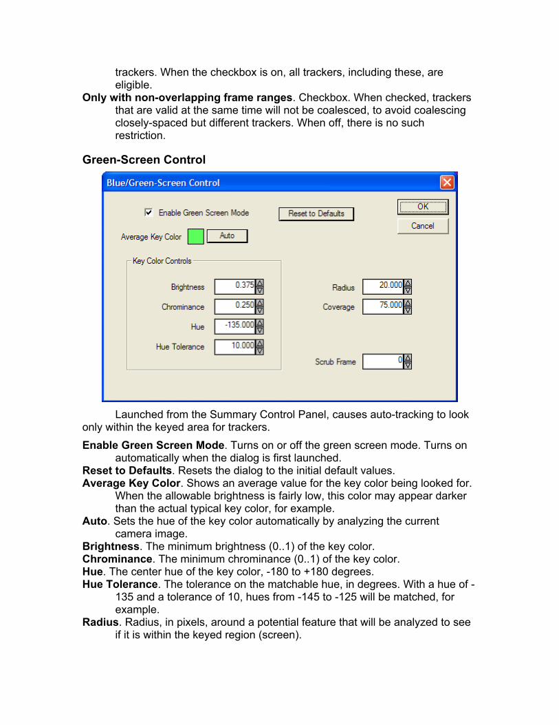
trackers. When the checkbox is on, all trackers, including these, are eligible.
Only with non-overlapping frame ranges. Checkbox. When checked, trackers that are valid at the same time will not be coalesced, to avoid coalescing closely-spaced but different trackers. When off, there is no such restriction.
Green-Screen Control
Launched from the Summary Control Panel, causes auto-tracking to look
only within the keyed area for trackers. Enable Green Screen Mode. Turns on or off the green screen mode. Turns on
automatically when the dialog is first launched. Reset to Defaults. Resets the dialog to the initial default values. Average Key Color. Shows an average value for the key color being looked for.
When the allowable brightness is fairly low, this color may appear darker than the actual typical key color, for example.
Auto. Sets the hue of the key color automatically by analyzing the current camera image.
Brightness. The minimum brightness (0..1) of the key color. Chrominance. The minimum chrominance (0..1) of the key color. Hue. The center hue of the key color, -180 to +180 degrees. Hue Tolerance. The tolerance on the matchable hue, in degrees. With a hue of -
135 and a tolerance of 10, hues from -145 to -125 will be matched, for example.
Radius. Radius, in pixels, around a potential feature that will be analyzed to see if it is within the keyed region (screen).
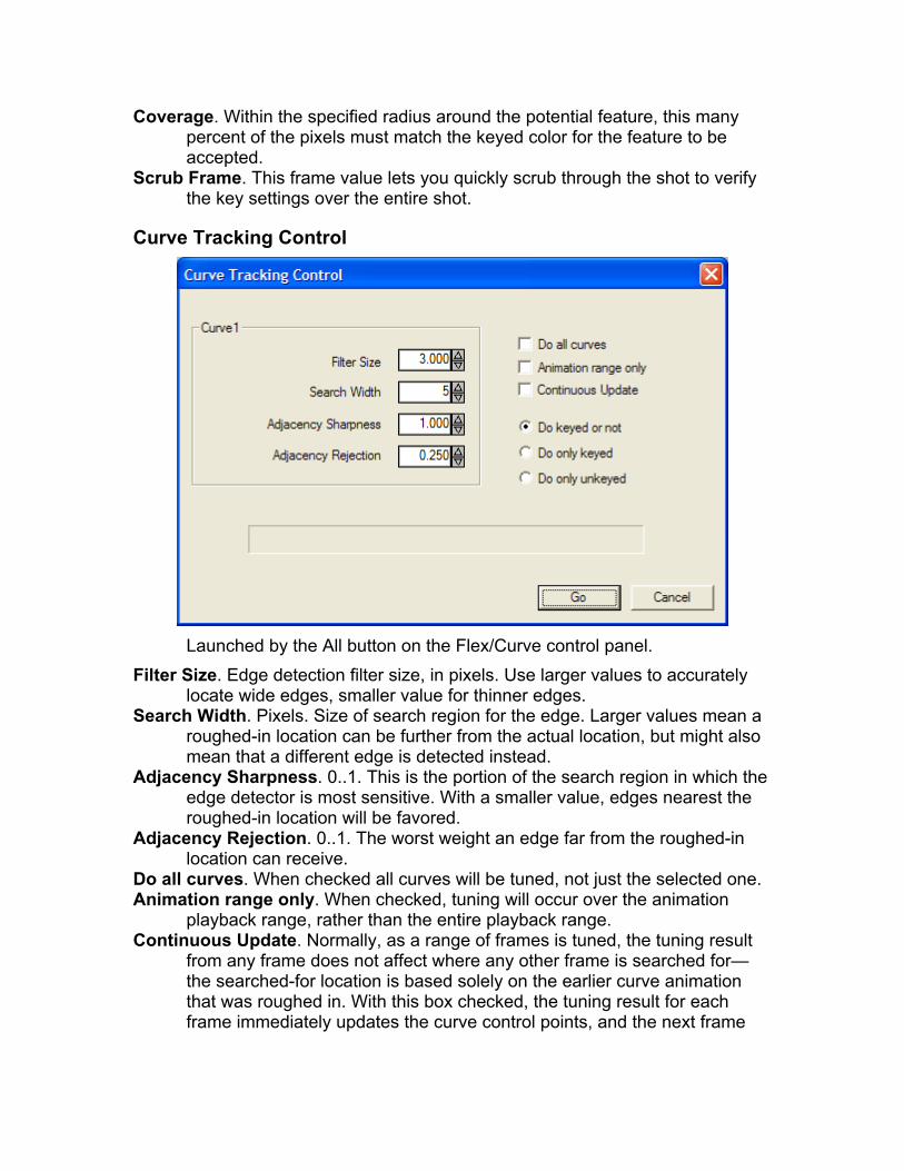
Coverage. Within the specified radius around the potential feature, this many percent of the pixels must match the keyed color for the feature to be accepted.
Scrub Frame. This frame value lets you quickly scrub through the shot to verify the key settings over the entire shot.
Curve Tracking Control
Launched by the All button on the Flex/Curve control panel.
Filter Size. Edge detection filter size, in pixels. Use larger values to accurately locate wide edges, smaller value for thinner edges.
Search Width. Pixels. Size of search region for the edge. Larger values mean a roughed-in location can be further from the actual location, but might also mean that a different edge is detected instead.
Adjacency Sharpness. 0..1. This is the portion of the search region in which the edge detector is most sensitive. With a smaller value, edges nearest the roughed-in location will be favored.
Adjacency Rejection. 0..1. The worst weight an edge far from the roughed-in location can receive.
Do all curves. When checked all curves will be tuned, not just the selected one. Animation range only. When checked, tuning will occur over the animation
playback range, rather than the entire playback range. Continuous Update. Normally, as a range of frames is tuned, the tuning result
from any frame does not affect where any other frame is searched for—the searched-for location is based solely on the earlier curve animation that was roughed in. With this box checked, the tuning result for each frame immediately updates the curve control points, and the next frame

will be looked for based on the prior search result. This can allow you to tune a curve without previously roughing it in.
Do keyed or not. All frames will be keyed, whether or not they have a key already.
Do only keyed. Add keys only to frames that are already have keys, typically to tune up a few roughed in keys.
Don only unkeyed. Only frames without keys will be tuned. Use to tune without adversely affecting frames that have already been carefully manually keyed.

Menu Reference
File Menu Many entries are Windows-standard. For example, File/New clears the
scene and also opens the Shot/Add Shot dialog. File/Merge. Merges a previously-written SynthEyes .sni scene file with the
currently-open one, including shots, objects, trackers, meshes, etc. Most elements are automatically assigned unique names to avoid conflicts, but a dialog box lets you select whether or not trackers are assigned unique names.
File/Import/Shot. Clears the scene and opens the Shot/Add Shot dialog, if there are no existing shots, or adds an additional shot if one or more shots are already present.
File/Import/Mesh. Imports a DXF or Alias/Wavefront OBJ mesh as a test object. File/Import/Tracker Locations. Imports a text file composed of lines: x_value
y_value z_value Tracker_name. For each line, if there is an existing tracker with that name, its seed position is set to the coordinates given. If there is no tracker with that name, a new one is created with the specified seed coordinates. Use to import a set of seed locations from a pre-existing object model or set measurements, for example. New trackers use settings from the tracker panel, if it is open. See the section on merging files.
File/Import/Extra Points. Imports a text file consisting of lines with x, y, and z values, each line optionally preceded or followed by an optional point name. A helper point is created for each line. The points might have been determined from on-set surveying, for example; this option allows them to be viewed for comparison. See the section on merging files.
Export Again. Redoes the last export, saving time when you are exporting repeatedly to your CG application.
Find New Scripts. Causes SynthEyes to locate any new scripts that have been placed in the script folder since SynthEyes started, making them available to be run.
Submit for batch. The current scene is submitted for batch processing by writing it into the queue area. It will not be processed until the Batch Processor is running, and there are no jobs before it.
Batch Process. SynthEyes opens the batch processing window and begins processing any jobs in the queue.
Batch Input Queue. Opens a Windows Explorer to the batch input queue folder, so that the queue can be examined, and possibly jobs removed or added.
Batch Output Queue. Opens a Windows Explorer to the batch output queue folder, where completed jobs can be examined or moved to their final destinations.
Exporter Outputs. Opens a Windows Explorer to the default exporter folder.
Edit Menu Undo. Undo the last operation, changes to show what, such as “Undo Select
Tracker.” Redo. Re-do an operation previously performed, then undone. Select same color. Select all the (un-hidden) trackers with the same color as the
one(s) already selected. Select All etc affect the tracker selections, not objects in the 3-D viewports. Invert Selection. Select unselected trackers, unselect selected trackers. Clear Selection. Unselect all trackers. Delete. Delete selected objects and trackers. Hide unselected. Hide the unselected trackers Hide selected. Hide the selected trackers Reveal selected. Reveal (un-hide) the selected trackers (typically from the
lifetimes panel). Reveal nnn trackers. Reveal (un-hide) all the trackers currently hidden, ie nnn
of them. Edit Scene Settings affects the current scene only. Edit Preferences contains some of the same settings; these do not affect the
current scene, but are used only when new scenes are created. Reset Preferences. Set all preferences back to the initial factory values. Gives
you a choice of presets for a light- or dark-colored user interface, appropriate for office or studio use, respectively.
Edit Keyboard Map. Brings up a dialog allowing key assignments to be altered.
View Menu Reset View. Resets the camera view so the image fills its viewport. Expand to Fit. Same as Reset View. Reset Time Bar. Makes the active frame range exactly fill the displayable area. Rewind. Set the current time to the first active frame. To End. Set the current time to the last active frame. Play in Reverse. When set, replay or tracking proceeds from the current frame
towards the beginning. Frame by Frame. Displays each frame, then the next, as rapidly as possible. Quarter Speed. Play back at one quarter of normal speed. Half Speed. Play back at one half of normal speed. Normal Speed. Play back at normal speed (ie the rated frame per second
value), dropping frames if necessary. Note: when the Tracker panel is selected, playback is always frame-by-frame, to avoid skipping frames in the track.
Double Speed. Play back at twice normal speed, dropping frames if necessary. Show Trackers. Turns on or off the tracker rectangles in the camera view. Show Image. Turns the main image’s display in the camera view on and off. Show 3-D Points. Controls the display of the solved position marks (X’s). Show 3-D Seeds. Controls the display of the seed position marks (+’s). Only Camera01’s trackers. Show only the trackers of the currently-selected
camera or object. When checked, trackers from other objects/cameras are
hidden. The camera/object name changes each time you change the currently-selected object/camera on the Shot menu.
Show Meshes. Controls display of object meshes in the camera viewport. Meshes are always displayed in the 3-D viewports.
Solid Meshes. When on, meshes are solid in the camera viewport, when off, wire frame. Meshes are always wireframe in the 3-D viewports.
Show Tracker Trails. When on, trackers show a trail into the future(red) and past(blue).
Show Tracker Posns. Turns the tracker position curves on and off in the tracker graph viewport.
Show 3-D Errors. Turns the tracker error curves on and off in the tracker graph viewport.
Show Lens Grid. Controls the display of the lens distortion grid (only when the Lens control panel is open).
Shadows. Show ground plane or on-object shadows in perspective window. This setting is sticky from SynthEyes run to run.
Double Buffer. Slightly slower but non-flickery graphics. Turn off only when maximal playback speed required.
Only Selected Splines. When checked, the selected spline, and only the selected spline, will be shown, regardless of its Show This Spline status.
Sort Alphabetic. When on, trackers are listed alphabetically in the lifetimes tracker listing. Otherwise, they are listed by start time (end time for backwards tracking).
Sort By Error. Trackers are sorted by their total 3-D error, most to least, making it easy to find the noisiest trackers.
Only selected in lifetimes. When on, only selected trackers are listed in the lifetimes viewport.
Track Menu Selected Only. When checked, only selected trackers are run while tracking.
Normally, any tracker which is not Locked is processed. Hand-Held: Predict. Uses previously-tracked trackers as a guide to predict
where a tracker will next appear, facilitating tracking of jittery hand-held shots.
Hand-Held: Sticky. Use for very irregular features poorly correlated to the other trackers. The tracker is looked for at its previous location. With both hand-held modes off, trackers are assumed to follow fairly smooth paths.
Stop on auto-key. Causes tracking to stop whenever a key is added as a result of the Key spinner, making it easy to manually tweak the added key locations.
Preroll by Key Smooth. When tracking starts from a frame with a tracker key, SynthEyes backs up by the number of Key Smooth frames, and retracks those frames to smooth out any jump caused by the key.
Pan to Follow. The camera view pans automatically to keep selected trackers centered. This makes it easy to see the broader context of a tracker.

ZWT auto-calculation. The 3-D position of each zero-weighted tracker is recomputed whenever it may have changed. With many ZWTs and long tracks, this might slow interactive response; use this item to temporarily disable recalculation if desired.
Combine Trackers. Combine all the selected trackers into a single tracker, and delete the originals.
Add Many Trackers. After a shot is auto-tracked and solved, additional trackers can be added efficiently using the dialog.
Cross Link by Name. The selected trackers are linked to trackers with the same name, except for the first character, on other objects. If the tracker’s object is solved Indirectly, it will not link to another Indirectly-solved object. It also will not link to a disabled object.
(Tool Scripts). Any tool-type scripts will appear on the Track menu for execution. Such scripts can reach into the current scene to act as scripted importers, gather statistics, produce output files, or make changes. Standard scripts include Filter Lens F.O.V., Invert Perspective, Select by type, Motion capture calibrate, Shift constraints, etc. See the Sizzle reference manual for information on writing scripts.
Shot Menu Add Shot. Adds a new shot and camera to the current workspace. This is
different than File/New, which deletes the old workspace and starts a new one! SynthEyes will solve all the shots at the same time when you later hit Go, taking links between trackers into account. Use the camera and object list at the end of the Shot menu to switch between shots.
Edit Shot. Brings up the shot settings dialog box (same as when adding a shot) so that you can modify settings. Switching from interlaced to noninterlaced or vice versa will require retracking the trackers.
Change Shot Images. Allows you to select a new movie or image sequence to replace the one already set up for the present shot. Useful to bring in a higher or lower-resolution version, or one with color or exposure adjustments. Warning: changes to the shot length or aspect ratio will adversely affect previously-done work.
Image Preparation. Brings up the image preparation dialog (also accessed from the shot setup dialog), for image preparation adjustments, such as region-of-interest control, as well as image stabilization.
Enable Prefetch. Turns the image prefetch on and off. When off, the cache status in the timebar will not be updated as accurately.
Add Moving Object. Adds a new moving object for the current shot. Add trackers to this object and SynthEyes will solve for its trajectory. The moving object shows as a diamond-shaped null in the 3-D workspace.
Remove Moving Object. Removes the current object. If it is a camera, it must not have any attached objects; if it is removed the whole shot goes with it.
(Camera and Object List). This list of cameras and objects appears at the end of the shot menu, showing the current object or camera, and allowing you

to switch to a different object or camera. Selecting an object here is different than selecting an object in a 3-D viewport.
Window Menu (Control Panel List). Allows you to change the control panel using standard
Windows menu accelerator keystrokes. Floating Panel. Click to float the control panel as an independent window. This
may makes better use of your screen space, especially with larger images or multiple monitor configurations
Floating Camera. Click to float the camera view independently. The camera view will be empty in the standard viewport configurations. Mac OS X Only: clicking the title bar of the camera view, for example to move it, will send the command view behind the camera view, if the command view is also floated. Unfloat and refloat the command view.
Viewport Manager. Starts the viewport layout manager, which allows you to change and add viewport configurations to match your working style and display system geometry.
Help Menu Commands labeled with an asterisk(*) require a working internet
connection, those with a plus sign(+) require a properly-configured support login as well. An internet connection is not required for normal SynthEyes operation, only for acquiring updates, support, etc. Help HTML. Opens the SynthEyes help file (from disk) in your web browser. Help PDF. Opens the PDF version of the help file: the PDF’s bookmarks make
this handy. Note: PDF help is a separate download for the demo version. Sizzle PDF. Opens the Sizzle scripting language manual. Read Messages+. Opens the web browser to a special message page
containing current support information, such as the availability of new scripts, updates, etc. This page is monitored automatically; this is equivalent to the Msg button on the toolbar.
Suggest Features+. Opens the Feature-Suggestion page for SynthEyes, allowing you to submit suggestions, as well as read other suggestions and comment and vote on them. (Not available on the demo version: send mail to support with questions/comments/suggestions.)
Tech Support Site*. Opens the technical support page of the web site. Tech Support Mail*. Opens an email to technical support. Be sure to include a
good Subject line! (Email support is available for one year after purchase.) Report a credit*. Hey, we all want to know! Drop us a line to let us know what
projects SynthEyes has been used in. Website/Home*. Opens the SynthEyes home page for current SynthEyes news. Website/Tutorials*. Opens the tutorials page. Website/Forum*. Opens the SynthEyes forum. Register. Launches a form to enter information required to request SynthEyes
authorization. Information is placed on the Windows clipboard.
Authorize. After receiving new authorization information, copy it to the Windows clipboard, then select Authorize to load the new information.
Set Update Info. Allows you to update your support-site login, and control how often SynthEyes checks for new builds and messages.
Check for Updates+. Manually tells SynthEyes to go look for new builds and messages. Use this periodically if you have dialup and set the automatic-check strategy to never. Generally equivalent to the D/L button on the toolbar.
Install Updated. If SynthEyes has successfully downloaded an updated build (D/L button is green), this item will launch the installation.
About. Current version information.
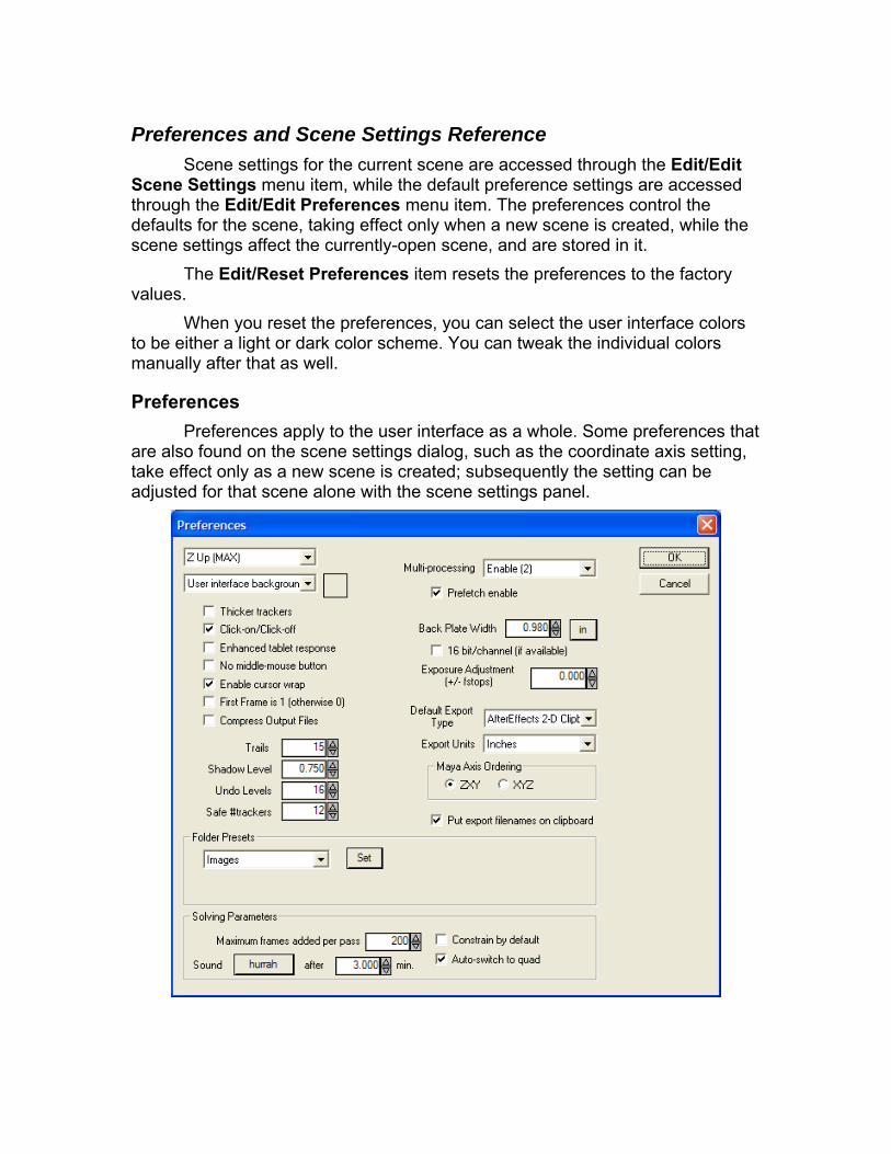
Preferences and Scene Settings Reference Scene settings for the current scene are accessed through the Edit/Edit
Scene Settings menu item, while the default preference settings are accessed through the Edit/Edit Preferences menu item. The preferences control the defaults for the scene, taking effect only when a new scene is created, while the scene settings affect the currently-open scene, and are stored in it.
The Edit/Reset Preferences item resets the preferences to the factory values.
When you reset the preferences, you can select the user interface colors to be either a light or dark color scheme. You can tweak the individual colors manually after that as well.
Preferences Preferences apply to the user interface as a whole. Some preferences that
are also found on the scene settings dialog, such as the coordinate axis setting, take effect only as a new scene is created; subsequently the setting can be adjusted for that scene alone with the scene settings panel.
16 bit/channel (if available). Store all 16 bits per channel from a file, producing more accurate image, but consuming more storage.
After … min. Spinner. The calculation-complete sound will be played if the calculation takes longer than this number of minutes.
Auto-switch to quad. Controls whether SynthEyes switches automatically to the quad viewport configuration after solving. Switching is handy for beginners but can be cumbersome in some situations for experts, so you can turn it off.
Axis Setting. Selects the coordinate system to be used. Back Plate Width. Width of the camera’s active image plane, such as the film or
imager. Back Plate Units. Shows in for inches or mm for millimeters, click it to change
the display units for this panel, and the default for the shot setup panel. Click-on/Click-off. Checkbox. When turned on, the camera view, mini-tracker
view, 3-D viewports, perspective view, and spinners are affected as follows: clicking the left or middle mouse button turns the mouse button on, clicking again turns it off. Instead of dragging, you will click, move, and click. This might help reduce strain on your hand and wrist.
Color Settings. (Drop-down and color swatch) Change the color of many user-interface elements. Select an element with the drop-down menu, see the current color on the swatch, and click the swatch to bring up a Windows dialog box that lets you change the color.
Compress Output Files. When turned on, SynthEyes scene files are compressed as they are written. Compressed files occupy about half the disk space, but take substantially longer to write, and somewhat longer to read.
Constrain by default (else align). If enabled, constraints are applied rigorously, otherwise, they are applied by rotating/translating/scaling the scene without modifying individual points. This is the default for the checkbox on the solver panel, used when a new scene is created.
Default Export Type. Selects the export file type to be created by default. Enable cursor wrap. When the cursor reaches the edge of the screen, it is
wrapped back around onto the opposite edge, allowing continuous mouse motion. Disable if using a tablet, or under Virtual PC. Enabled by default, except under Virtual PC.
Enhanced Tablet Response. Some tablet drivers, such as Wacom, delay sending tablet and keyboard commands when SynthEyes is playing shots. Turning on this checkbox slows playback slightly to cause the tablet driver to forward data more frequently.
Export Units. Selects the units (inches, meters, etc) in the exported files. Some units may be unavailable in some file types, and some file types may not support units at all.
Exposure Adjustment: increases or decreases the shot exposure by this many f-stops as it is read in. The main window updates as you change this. Supported only for certain image formats, such as Cineon and DPX.

First Frame is 1 (otherwise 0). Turn on to cause frame numbers to start at 1 on the first frame.
Folder Presets. Helps workflow by letting you set up default folders for various file types: batch input files, batch output files, images, scene files, imports, and exported files. Select the file type to adjust, then hit the Set button.
Maximum frames added per pass. During solving, limiting the number of frames added prevents new tentative frames from overwhelming an existing solution. You can reduce this value if the track is marginal, or expand it for long, reliable tracks.
Maya Axis Ordering. Selects the axis ordering for Maya file exports. Multi-processing. Drop-down list. Enable or disable SynthEyes use of multiple
processors, hyper-threading, or cores on your machine. The number in parentheses for the Enable item shows the number of processors/cores/threads on your machine. The Single item causes the multiprocessing algorithms to be used, but only with a single thread, mainly for testing.
No middle-mouse button. For use with 2-button mice, trackballs, or Microsoft Intellipoint software on Mac OSX. When turned on, ALT/Command-Left pans the viewports and ALT/Command-Right links trackers.
Prefetch enable. The default setting for whether or not image prefetch is enabled. Disable if image prefetch overloads your processor, especially if shot imagery is located on a slow network drive.
Put export filenames on clipboard. When checked (by default), whenever SynthEyes exports, it puts the name of the output file onto the clipboard, to make it easier to open in the target application.
Safe #trackers. Spinner. Used to configure a user-controlled desired number of trackers in the lifetimes panel. If the number is above this limit, the lifetime color will be white or gray, which is best. Below this limit, but a still acceptable value, the background is the Safe color, by default a shade of green: the number of trackers is safe, but not your desired level.
Shadow Level. Spinner. The shadow is dead black, this is an alpha that ranges 0 to 1, at 1 the shadow has been mixed all the way to black.
Sound [hurrah]. Button. Shows the name of the sound to be played after long calculations.
Thicker trackers. When check trackers will be 2-pixels wide (instead of 1) in the camera, perspective, and 3-D views. Turned on by default for, and intended for use with, higher-resolution displays.
Trails. The number of frames in each direction (earlier and later) shown in the camera view for trackers and blips.
Undo Levels. The number of operations that are buffered and can be undone. If some of the operations consume much memory (especially auto-tracking), the actual limit may be much smaller.
Scene Settings The scene settings, accessed through Edit/Edit Scene Settings, apply to
the current scene (file).

The perspective-window sizing controls are found here. Normally, SynthEyes bases the perspective-window sizes on the world size of the active camera or object. The resulting actual value of the size will be shown in the spinner, and no “key” will be indicated (a red frame around the spinner).
If you change the spinner, a key frame will be indicated (though it does not animate). After you change a value, and the key frame marker appears, it will no longer change with the world size. You can reset an individual control to the factory default by right-clicking the spinner.
There are several buttons that transfer the sizing controls back and forth to the preferences: there is no separate user interface for these controls on the Preferences panel. If a value has not been changed, that value will be saved in the preferences, so that when the preferences are applied (to a new scene, or recalled to the current scene), unchanged values will be the default factory values, computed from the current world size.
Important Note: the default sizes are dynamically computed from the current world size. If you think you need to change the size controls here, especially tracker size and far clip, this probably indicates you need to change your world size instead.
Axis Setting. Selects the coordinate system to be used. Camera Size. 3-D size of the camera icon in the perspective view. Far Clip. Far clip distance in the perspective view Key Mark Size. Size of the key marks on camera/object seed paths. Light Size. Size of the light icon in the perspective view.

Load from Prefs. Loads the settings from the preferences (this is the same as what happens when a new scene is created).
Mesh Vertex Size. Size of the vertex markers in the perspective view—in pixels, unlike the other controls here.
Near Clip. Near clipping plane distance. Object Size. Size of the moving-object icon in the perspective view. Orbit Distance. The distance out in front of the camera about which the camera
orbits, on a camera rotation when no object or mesh is selected. Reset to defaults. The perspective window settings are set to the factory
defaults (which vary with world size). The preferences are not affected. Save to prefs. The current perspective-view settings are saved to the
preferences, where they will be used for new scenes. Note that unchanged values are flagged, so that they continue to vary with world size in the new scene.
Tracker Size. Size of the tracker icon (triangle) in the perspective view.

Keyboard Reference SynthEyes has a user-assignable keyboard map, accessed through the
Edit/Edit Keyboard Map menu item.
The first list box shows a context (see the next section), the second a key,
and the third shows the action assigned to that key (there is a NONE entry also). The Shift, Control, and Alt (Mac: Command) checkboxes are checked if the corresponding key must also be down; the panel shown here shows a Select All operation will result from Control-A in the “Main” context.
Because several keys can be mapped to the same action, if you want to change Select All from Control-A to Control-T, say, you should set Control-A back to NONE, and when configuring the Control-T, select the T, then the Control checkbox, and finally then change the action to Select All.
Time-Saving Hint: after opening any of the drop-down lists (for context, key, or action), hit a key to move to that part of the list quickly.
The Change to button sets the current key combination to the action shown, which is the last significant action performed before opening the keyboard manager. In the example, it would be “Reset Preferences.”
Change to makes it easy to set up a key code: perform the action, open the keyboard manager, select the desired key combination, then hit Change to. The Change to button may not always pick up a desired action, especially if it is a button—use the equivalent menu operation instead.
You can quickly remove the action for a key combination using the NONE button.
Changes are temporary for this run of SynthEyes unless the Save button is clicked. The Factory button resets the keyboard assignments to their factory defaults. Listing shows the current key assignments; see the Default Key Assignments section below.

Key Contexts SynthEyes allows keys to have different functions in different places; they
are context-dependent. The contexts include:
• The main window/menu • The camera view • Any perspective view • Any 3-D viewport • Any command panel
There is a separate context for each command panel. In each context, there is a different set of applicable operations, for
example, the perspective window has different navigation modes, whereas trackers can only be created in the camera window. When you select a context on the keyboard manager panel, only the available operations in that context will be listed.
Here comes the tricky part: when you hit any key, several different contexts might apply. SynthEyes checks the different contexts in a particular order, and the first context that provides an action for that key is the context and action that is applied. In order, SynthEyes checks
• The selected command panel context • The context of the window in which the key was struck • The main window/menu context • The context of the camera window, if it is visible, even if the cursor was not in
the camera window. This is a bit complex but should allow you to produce many useful effects.
Note that the 4th rule does have an “action at a distance” flavor that might surprise you on occasion, though it is generally useful.
You may notice that some operations appear in the main context and the camera, viewport, or perspective contexts. This is because the operation appears on the main menu and the corresponding right-click menu. Generally you will want the main context.
Keys in the command-panel contexts can only be executed when that command-panel is open. You can not access a button on the solver panel when the tracker panel is open, say. The solver panel’s context is not active, so the key will not even be detected, the solver panel functionality is unavailable when it isn’t open, and changing settings on hidden panels makes for tricky user interfaces (though there are some actions that basically do this).
Default Key Assignments Rather than imprecisely try to keep track of the key assignments here,
SynthEyes provides a Listing button, which produces and opens a text file. The file shows the current assignments sorted by action name and by the key, so you can find the key for a given action, or see what keys are unused.
The listing also shows the available actions, so you can see what functions you can assign a key to. All menu actions can be assigned, as can all buttons, check boxes, and radio boxes on the main control panels, plus a variety of special actions.
You will see the current key assignment listed after menu items and in the tooltips of most buttons, checkboxes, and radio buttons on command panels. These will automatically update when you close the keyboard manager.
Fine Print Do not assign a function to plain Z or apostrophe/double-quote. These
keys are used as an extra click-to-place shift key in the camera view, and any Z or ’/” keyboard operation will be performed over and over while the key is down for click-to-place.
The Reset Zoom action does two somewhat different things: with no shift key, it resets the camera view so the image fills the view. When the shift key is depressed, it resets the camera view so that the image and display pixels are 1:1 in the horizontal direction, ie the image is “full size.” Consequently, you need to set up your key assignments so that the fill operation is un-shifted, and the 1:1 operation is shifted.
The same thing applies to other buttons whose functionality depends on the mouse button. If you shift-click a button to do something, then the function performed will still depend on the shift setting of the keyboard accelerator key.
There may be other gotchas scattered through the possible actions; you should be sure to verify their function in testing before trying them in your big important scene file. You can check the undo button to verify the function performed, for example.
The “My Layout” action sets the viewport configuration to one named “My Layout” so that you can quickly access your own favorite layout.
Key Assignment File SynthEyes stores the keyboard map in the file keybd.ini. If you are very
daring, you can modify the file using the SynthEyes keyboard manager, Notepad, or any text editor. SynthEyes’ exact action and key names must be used, as shown in the keyboard map listing. There is one keybd.ini file for each user, located like this: C:\Documents and Settings\YourNameHere\Application Data\SynthEyes\keybd.ini (PC)
/Users/YourNameHere/Library/Application Support/SynthEyes/keybd.ini (Mac OSX)
The preferences data and viewport layouts are also stored in prefs.dat and layout.ini files in this folder. Note that the Application Data folder may be “hidden” by the Windows Explorer; there is a Folder Option to make it visible.

Support Technical support is available through [email protected]. A
response should generally be received within 24 hours except on weekends. SynthEyes is written, supported, and ©2003-2007 by Andersson
Technologies LLC. This software is based in part on the work of the Independent JPEG
Group, http://www.ijg.org. Based in part on TIFF library, http://www.libtiff.org, Copyright ©1988-1997 Sam Leffler, and Copyright ©1991-1997 Silicon Graphics, Inc. Also based in part on the LibPNG library, Glenn Randers-Pehrson and various contributing authors. Some toolbar images from the GlyFX library, (c)2001, 2002 PerthWeb Pty Ltd.
OpenEXR library Copyright (c) 2004, Industrial Light & Magic, a division of Lucasfilm Entertainment Company Ltd. Portions contributed and copyright held by others as indicated. All rights reserved. Neither the name of Industrial Light & Magic nor the names of any other contributors to this software may be used to endorse or promote products derived from this software without specific prior written permission. THIS SOFTWARE IS PROVIDED BY THE COPYRIGHT HOLDERS AND CONTRIBUTORS "AS IS" AND ANY EXPRESS OR IMPLIED WARRANTIES, INCLUDING, BUT NOT LIMITED TO, THE IMPLIED WARRANTIES OF MERCHANTABILITY AND FITNESS FOR A PARTICULAR PURPOSE ARE DISCLAIMED. IN NO EVENT SHALL THE COPYRIGHT OWNER OR CONTRIBUTORS BE LIABLE FOR ANY DIRECT, INDIRECT, INCIDENTAL, SPECIAL, EXEMPLARY, OR CONSEQUENTIAL DAMAGES (INCLUDING, BUT NOT LIMITED TO, PROCUREMENT OF SUBSTITUTE GOODS OR SERVICES; LOSS OF USE, DATA, OR PROFITS; OR BUSINESS INTERRUPTION) HOWEVER CAUSED AND ON ANY THEORY OF LIABILITY, WHETHER IN CONTRACT, STRICT LIABILITY, OR TORT (INCLUDING NEGLIGENCE OR OTHERWISE) ARISING IN ANY WAY OUT OF THE USE OF THIS SOFTWARE, EVEN IF ADVISED OF THE POSSIBILITY OF SUCH DAMAGE.
All of the contributors’ efforts are greatly appreciated.