t movidrive md 60a drive inverters · 2014-08-01 · movidrive® tabular positioning 5 project...
TRANSCRIPT

UL®
UL®C
T
MOVIDRIVE® MD_60ADrive Inverters
Addendum to the System Manual
Table Positioning
Edition 01/200009
18 4
112
/ 012
000
2 MOVIDRIVE® Tabular Positioning
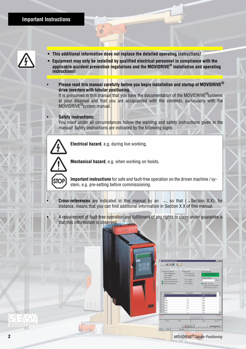
Important Instructions
• Please read this manual carefully before you begin installation and startup of MOVIDRIVE®
drive inverters with tabular positioning.It is presumed in this manual that you have the documentation of the MOVIDRIVE® systemsat your disposal and that you are accquainted with the contents, particularly with theMOVIDRIVE® system manual.
• Safety instructions:You must under all circumstances follow the warning and safety instructions given in themanual! Safety instructions are indicated by the following signs:
Electrical hazard, e.g. during live working.
Mechanical hazard, e.g. when working on hoists.
Important instructions for safe and fault-free operation on the driven machine / sy-stem, e.g. pre-setting before commissioning.
• Cross-references are indicated in this manual by an →, so that (→Section X.X), forinstance, means that you can find additional information in Section X.X of this manual.
• A requirement of fault-free operation and fulfillment of any rights to claim under guarantee isthat this information is observed.
• This additional information does not replace the detailed operating instructions!
• Equipment may only be installed by qualified electrical personnel in compliance with the applicable accident prevention regulations and the MOVIDRIVE® installation and operating instructions!

Contents
MOVIDRIVE® Table Positioning 3
Page
1 Project Planning ........................................................................................41.1 Applications ..................................................................................................................... 41.2 Hardware and Software Requirements.............................................................................5
1.2.1 PC and Software.................................................................................................... 51.2.2 Inverters, Motors and Encoders ............................................................................5
1.3 Functions .........................................................................................................................61.4 Scaling the Drive..............................................................................................................71.5 Limit Switches, Reference Cam and Machine Zero Point .................................................81.6 Binary Coding of the Tabular Positions............................................................................8
2 Installation...............................................................................................92.1 Software ..........................................................................................................................92.2 MOVIDRIVE® DIO11A Input/Output Option.....................................................................102.3 MOVIDRIVE® DIP11A Absolute Encoder Option ............................................................. 112.4 Function of the DI12...DI17 Input Terminals ..................................................................122.5 Connecting the Limit Switches ......................................................................................12
3 Startup.................................................................................................. 133.1 General ..........................................................................................................................133.2 Preparations ..................................................................................................................133.3 Starting the "Table Positioning" Program ....................................................................... 13
3.3.1 Setting the General Parameters ...........................................................................143.3.2 Entering the Table Positions ................................................................................ 16
3.4 Parameters .................................................................................................................... 193.5 Starting up the Drive......................................................................................................19
3.5.1 Operating Modes ................................................................................................. 193.5.2 Reference Mode .................................................................................................. 213.5.3 Jog Mode ............................................................................................................223.5.4 Teach Mode.........................................................................................................233.5.5 Automatic Operation............................................................................................24
4 Operation and Service ............................................................................... 264.1 Pulse Diagrams..............................................................................................................26
4.1.1 Reference Mode and Automatic Operation ..........................................................264.1.2 Jog Mode and Teach Mode .................................................................................27
4.2 Fault Information ...........................................................................................................284.3 Fault Signals ..................................................................................................................29
For project planning and startup of "Table Positioning" you require the following SEW documenta-tion:• MOVIDRIVE® MD_60A system manual, part number 0919 1119• "IPOSplus® Positioning and Sequence Control" manual, part number 0919 1712
If you are using an absolute encoder as external encoder, you also need:• "MOVIDRIVE® DIP11A Absolute Encoder" manual, part number 0919 5912

4 MOVIDRIVE® Tabular Positioning
1 Project Planning
1 Project Planning
1.1 Applications
Tabular positioning is particularly recommendable for the following application areas:• Materials handling
– Trolleys
– Hoists– Rail vehicles
• Logistics
– Storage and retrieval units for high-bay warehouses– Traverse carriages
• Palletizing / Handling– Multi-axis handling robots
– Overhead systems
The following advantages are characterisic of tabular positioning:
• User-friendly interfaces
• You only need to enter the parameters necessary for tabular positioning (gear ratios, speeds,diameters).
• Guided parameter-setting replaces complex programming.• Monitor operation provides optimum diagnostics.
• The user does not need to have programming skills.
• Long-term familiarization with the process is not necessary.

MOVIDRIVE® Tabular Positioning 5
Project Planning 1
1.2 Hardware and Software Requirements
1.2.1 PC and Software
Tabular postioning is implemented as an IPOSplus® program and is a component of the MOVI-TOOLS software from SEW. To use MOVITOOLS you need a PC with a Windows® 95,Windows® 98 oder Windows NT® 4.0 operating system.
1.2.2 Inverters, Motors and Encoders
• Inverters
Tabular positioning is possible with MOVIDRIVE® MDV60A or MOVIDRIVE® MDS60A units.Depending on the combination, either the DIO11A input/output MOVIDRIVE® option or theDIP11A absolute encoder option will be required.
Tabular positioning is not possible with the MOVIDRIVE® MDF60A as encoder feedback is notprovided by this inverter.
• Motors
– For operation with the MOVIDRIVE® MDV60A:
Asynchronous CT/CV servomotors, encoders installed as standard.DT/DV/D AC motors with incremental encoder option.
– For operation with the MOVIDRIVE® MDS60A:
Synchronous DS/DY servomotors, resolvers installed as standard.
• External encoders
– Interlocking connection between motor shaft and load:no external encoder necessary.
– Non-positive connection between motor shaft and load:
External encoder is required in addition to motor encoder/resolver.External incremental encoder → connection to basic unit via X14:
External absolute encoder → connection to DIP11A option via X62:
• Possible combinations
Connectionmotor shaft-load
Interlocking connection: noexternal encoder necessary Non-positive connection: external encoder necessary
External encoder type - Incremental encoder Absolute encoder
Reference travel Yes Yes No
RequiredMOVIDRIVE® option
Input/OutputType DIO11A
Input/OutputType DIO11A
Absolute encoderType DIP11A

6 MOVIDRIVE® Tabular Positioning
1 Project Planning
1.3 Functions
The "tabular positioning" application provides the following functions:• 32 tabular positions can be predefined and selected.
• For each positioning travel operation, the travel speed can be freely selected.
• For each positioning travel operation, the ramp can be set separately.• Software limit switches can be defined and evaluated.
• External encoders can be evaluated either as incremental or absolute encoders as required.
These functions are available in four operating modes:• Jog mode
– Via two binary inputs the drive can be turned either clockwise or anti-clockwise.
– Two binary inputs provide selection of two speeds; rapid and creep modes for precision posi-tioning.
• Teach mode
– Each single position can be approached in jog mode and then saved in teach mode.
• Reference mode
– A start command to a binary input inititiates a reference travel operation. The reference travelis used to determine the reference point (machine zero point) for the absolute positioningprocesses.
• Automatic operation
– Selection of the target position via five binary inputs (binary-coded).– Selected target position responds prior to travel operation via five binary outputs (binary-
coded).– Confirmation via five binary outputs that the target position has been reached.

MOVIDRIVE® Tabular Positioning 7
Project Planning 1
1.4 Scaling the Drive
The control system must know the number of encoder increments per travel distance to be able tocalculate the travel distance information for correct positioning of the drive.
Drives without an external encoder (positive connection):
For drives without an external encoder, you can carry out scaling automatically by starting up tabu-lar positioning. To do this you must enter the following data:
• Diameter of the drive wheel or spindle pitch
• Gear ratios gear unit (i gear unit)
• Gear ratios for additional gear unit (i additional gear unit).The scaling factor for pulse/distance [inc/mm] is therefore calculated according to the followingformula:
Pulses = 4096 × igear unit × iadditional gear unit
Distance = π × ddrive wheel or sspindle pitch
You can also enter the pulses/distance directly. If you enter a unit of measurement other than themillimeter [mm], this user-defined unit will also be used for the position of the software limitswitch, the reference offset and tabular positioning.
Drives with an external encoder (non- positive):For drives with an external encoder, you must activate and scale the external encoder prior to star-ting up tabular positioning. To do this you must carry out the following settings in Shell:• Set P941 "Source actual position", EXT. ENCODER (X14) for an incremental encoder or ABSO-
LUTE ENCODER (DIP). This setting can also be carried out during startup of tabular positioning.
02770AENFig.1: Set Source Actual Position
• P942...P944 Encoder factor numerator and denominator as well as the encoder scaling for theexternal encoder must be correctly set before tabular positioning is started up. These parame-ters are set on startup of the DIP11A absolute encoder option.
When tabular positioning is started up, scaling calculation is deactivated.
Further information on scaling the external encoder can be found in the manual "IPOSplus® Posi-tioning and Sequence Control" (part number 0919 1712) and in the manual "DIP11A AbsoluteEncoder Option" (part number 0919 5912).

8 MOVIDRIVE® Tabular Positioning
1 Project Planning
1.5 Limit Switches, Reference Cam and Machine Zero Point
Please observe the following instructions during project planning:
• The software limit switches must be positioned between the hardware limit switches.• When determining the reference point (position of the reference cam) and the software limit
switches, ensure that these do not overlap. If this happens, error message F78 "IPOS SW LimitSwitch" is generated during referencing.
• If the machine zero point (= reference point for tabular positioning) does not lie on the referencepoint, then you can enter a reference offset on starting up tabular positioning. The applicableformula in this case is: machine zero point = reference point + reference offset.In this way you can change the machine zero point without having to displace the reference cam.
1.6 Binary Coding of the Tabular Positions
The tabular positions must be given in binary code and are also acknowledged in binary code. Thistherefore means that DI13 (DO12) = 20 and DI17 (DO16) = 24.
No. DI13 (DO12) DI14 (DO13) DI15 (DO14) DI16 (DO15) DI17 (DO16)
0 "0" "0" "0" "0" "0"
1 "1" "0" "0" "0" "0"
2 "0" "1" "0" "0" "0"
3 "1" "1" "0" "0" "0"
4 "0" "0" "1" "0" "0"
5 "1" "0" "1" "0" "0"
6 "0" "1" "1" "0" "0"
7 "1" "1" "1" "0" "0"
8 "0" "0" "0" "1" "0"
9 "1" "0" "0" "1" "0"
10 "0" "1" "0" "1" "0"
11 "1" "1" "0" "1" "0"
12 "0" "0" "1" "1" "0"
13 "1" "0" "1" "1" "0"
14 "0" "1" "1" "1" "0"
15 "1" "1" "1" "1" "0"
16 "0" "0" "0" "0" "1"
17 "1" "0" "0" "0" "1"
18 "0" "1" "0" "0" "1"
19 "1" "1" "0" "0" "1"
20 "0" "0" "1" "0" "1"
21 "1" "0" "1" "0" "1"
22 "0" "1" "1" "0" "1"
23 "1" "1" "1" "0" "1"
24 "0" "0" "0" "1" "1"
25 "1" "0" "0" "1" "1"
26 "0" "1" "0" "1" "1"
27 "1" "1" "0" "1" "1"
28 "0" "0" "1" "1" "1"
29 "1" "0" "1" "1" "1"
30 "0" "1" "1" "1" "1"
31 "1" "1" "1" "1" "1"

MOVIDRIVE® Tabular Positioning 9
Installation 2
2 Installation
2.1 Software
Tabular positioning is a part of the SEW software MOVITOOLS. To install MOVITOOLS on your PC,please proceed as follows:
1. Insert the MOVITOOLS CD into the CD drive on your PC.2. From the control panel open up "Start\Run...".3. Enter "{Drive letter of your CD drive}: setup" and press the return key.4. The MOVITOOLS setup menu is displayed. Follow the instructions to be guided automatically
through installation.
Now you can start MOVITOOLS from the program manager. If a MOVIDRIVE® is connected to yourPC, select the correct interface (PC-COM) and select the Peer-to-Peer connection. Click the<Update> button to display the inverter in the "Connected Inverters" window.
02745AENFig. 2: MOVITOOLS window

10 MOVIDRIVE® Tabular Positioning
2 Installation
2.2 MOVIDRIVE® DIO11A Input/Output Option
For a positive connection between the motor shaft and the load (an external encoder is not requi-red) or for a non-positive connection and an external incremental encoder.
02736AENFig.3: Wiring diagram with DIO11A
X14:
X15:
X13:DIØØDIØ1DIØ2DIØ3DIØ4DIØ5
DCOMVO24DGNDST11ST12
123456789
1011
X10:
X22:
X23:
TF1DGNDDBØØ
DOØ1-CDOØ1-NODOØ1-NC
DOØ2VO24VI24
DGND
DI1ØDI11DI12DI13DI14DI15DI16DI17
DCOMDGND
DO1ØDO11DO12DO13DO14DO15DO16DO17DGND
123456789
10
123456789
10
123456789
1
5
5
1
6
9
9
6
=+ -24 V
DIO
123
123456
123456789
10
123456789
MDV (MDS)
X11
X12
S11S12
X13
X10
X14 X15ENCODER IN/OUT ENCODER IN
(RESOLVER IN)
12345
1234567891011
12345678910
123
SUPPLY OUT 24V=
mA V↔R ON OFF↔
X20
X21
X22
X23
IPOS output: MODE LowIPOS output: MODE HighIPOS output: value 1 (2^0)IPOS output: value 2 (2^1)IPOS output: value 4 (2^2)IPOS output: value 8 (2^3)IPOS output: value 16 (2^4)IPOS output: position reachedReference potential binary signals
IPOS input: MODE LowIPOS input: MODE HighIPOS input: function 1IPOS input: function 2IPOS input: function 3IPOS input: function 4IPOS input: function 5IPOS input: function 6Reference X22:DI1Ø...DI17Reference potential binary signals
TF inputReference potential binary signals/Brake
Relay contact/faultNO relay/faultNC relay /fault
Referenced+24V output+24V inputReference potential binary signals
Motor encoder:Incremental encoder (MDV) or resolver (MDS)
(Connection MOVIDRIVE operating instructions)→®
Input external encoderIncremental encoder 5 V TTL
(Connection MOVIDRIVE operating instructions)→ ®
/Controller inhibitEnable/rapid stopResetReference cam/Limit switch CW/Limit switch CCWReference X13:DIØØ...DIØ5+24V outputReference potentialRS-485+RS-485-

MOVIDRIVE® Tabular Positioning 11
Installation 2
2.3 MOVIDRIVE® DIP11A Absolute Encoder Option
For a positive connection between motor shaft and load and an external absolute encoder. For con-necting the absolute encoder, please observe the installation instructions in the manual "Position-ing with Absolute Encoder and DIP11A Absolute Encoder Option" (0919 5912).
02740AENFig. 4: Wiring diagram with DIP11A
X14:
X15:
X62:
X13:DIØØDIØ1DIØ2DIØ3DIØ4DIØ5
DCOMVO24DGNDST11ST12
123456789
1011
X10:
X60:
X61:
TF1DGNDDBØØ
DOØ1-CDOØ1-NODOØ1-NC
DOØ2VO24VI24
DGND
DI1ØDI11DI12DI13DI14DI15DI16DI17
DCOMDGND
DO1ØDO11DO12DO13DO14DO15DO16DO17DGND
123456789
10
123456789
10
123456789
1
1
5
5
5
1
6
6
9
9
9
6
=+ -24 V
MDV (MDS)
X11
X12
S11S12
X13
X10
X14 X15ENCODER IN/OUT ENCODER IN
(RESOLVER IN)
12345
1234567891011
12345678910
123
SUPPLY OUT 24V=
mA V↔R ON OFF↔
DIP
123456789
10
123456789
X60
X61
X62
Absolute encoder(Connection manual "Positioning with DIP11AAbsolute Encoder and Absolute Encoder Option")
→
IPOS output: MODE LowIPOS output: MODE HighIPOS output: value 1 (2^0)IPOS output: value 2 (2^1)IPOS output: value 4 (2^2)IPOS output: value 8 (2^3)IPOS output: value 16 (2^4)IPOS output: position reachedReference potential binary signals
IPOS input: MODE LowIPOS input: MODE HighIPOS input: function 1IPOS input: function 2IPOS input: function 3IPOS input: function 4IPOS input: function 5IPOS input: function 6Reference X22:DI1Ø...DI17Reference potential binary signals
TF inputReference potential binary signals/Brake
Relay contact/faultNO relay/faultNC relay /fault
Referenced+24V output+24V inputReference potential binary signals
Motor encoder:Incremental encoder (MDV) or resolver (MDS)
(Connection MOVIDRIVE operating instructions)→®
Input external encoder,Incremental encoder 5 V TTL
(Connection MOVIDRIVE operating instructions)→ ®
/Controller inhibitEnable/rapid stopResetReference cam/Limit switch CW/Limit switch CCWReference X13:DIØØ...DIØ5+24V outputReference potential binary signalsRS-485+RS-485-

12 MOVIDRIVE® Tabular Positioning
2 Installation
2.4 Function of the DI12...DI17 Input Terminals
The X22:DI12...DI17 binary inputs (DIO11A) or X60:DI12...DI17 (DIP11A) respectively have a diffe-rent significance depending on the operating mode which has been set. The operating modes areset via the binary inputs X22:DI1Ø and DI11 respective X60:DI1Ø and DI11.
Operating Modes:
Function of the DI12...DI17 Binary Inputs:
2.5 Connecting the Limit Switches
The cams of the limit switches must cover the travel distance up to the stop.
Use limit switches with NC contacts (low active) only!
02746AENFig. 5: Connecting the limit switches
Operating Mode Jog Mode Teach Mode Reference Mode Automatic Mode
DI1Ø: Mode Low "0" "1" "0" "1"
DI11: Mode High "0" "0" "1" "1"
Betriebsart Jog Mode Teach Mode Reference Mode Automatic Mode
DI12: Function 1 Reserved Strobe Start Referencing Start Positioning
DI13: Function 2 Jogging positive Position 20 Reserved Position 20
DI14: Function 3 Jogging negative Position 21 Reserved Position 21
DI15: Function 4 Rapid Position 22 Reserved Position 22
DI16: Function 5 Reserved Position 23 Reserved Position 23
DI17: Function 6 Reserved Position 24 Reserved Position 24
CW li
mit
switc
h
Distance of travel
CW drive inverter
CCW
lim
it sw
itch

MOVIDRIVE® Table Positioning 13
Startup 3
3 Startup
3.1 General
Correct project planning and fault-free installation are essential preconditions for successful start-up. Detailed information on project planning is contained in the MOVIDRIVE® system manualbelonging to the MOVIDRIVE® documentation package (order number 0919 3219).
Check installation and encoder connections according to the installation instructions contained inthe MOVIDRIVE® MD_60A operating instructions and also in this manual (Section 2, page 9).
Use an absolute encoder as external encoder (connection to DIP11A X62:), follow the instructionson installation and startup in the "DIP11A Absolute Encoder Option" manual (order no. 0919 5912).
3.2 Preparations
Before beginning startup of "Table Positioning" proceed as follows:
• Connect the inverter to the PC via the serial interface (RS-232, USS21A on PC-COM).
• Install the MOVITOOLS software on the PC (Section 2.1, page 9) and run the program.• Use <Shell> to start the inverter up.
– For MOVIDRIVE® MDV60A and DT/DV/D motors, use operating mode VFC-n-REG.&IPOS.
– For MOVIDRIVE® MDV60A and CT/CV motors, use operating mode CFC&IPOS.– For MOVIDRIVE® MDS60A and DS/DY motors, use operating mode SERVO&IPOS.
• Note the following for operation with an external encoder (absolute encoder or incrementalencoder).
– Absolute encoder: startup the DIP11A absolute encoder option; parameters P942...P944 areset automatically when you do this (→ manual "DIP11A Absolute Encoder Option", ordernumber 0919 5912).
– Incremental encoder: Set P942...P944 encoder factors numerator and denominator and theencoder scaling for the external encoder in Shell. You can find a detailed description of theparameters in the "IPOSplus® Positioning and Sequence Control System " manual, order num-ber 0919 1704.
• "0" signal to terminal X13:1 (DIØØ, /controller inhibit).
3.3 Starting the "Table Positioning" Program
• Start <Shell>.• In Shell, open "Startup/Table Positioning".
02747AENFig. 6: Starting the "Table Positioning" program

14 MOVIDRIVE® Table Positioning
3 Startup
3.3.1 Setting the General Parameters
Initial Startup:
When table positioning is started up for the first time, the window for setting the general parame-ters opens up immediately.
02749AENFig. 7: General parameters for table positioning
In this window you must carry out the following settings:
• If you are not using an external encoder: calculate scaling factor increments/distance.– Select "Diameter of driving wheel" or "Spindle slope" from the selection window and enter the
value in millimeters [mm].– Enter the i values for gear units and additional gears.
– Click on the <Calculation> button to calculate the scaling factor. The figures for Increments/Distance are entered as units of inc/mm.
You can also enter the scaling factor directly. In this case you can enter any particular unit ofmeasurement for the distance. This unit (user-defined unit) is then used for the position of thesoftware limit switch, the reference offset and the table positions.In drives with an external encoder the scaling calculation is deactivated.

MOVIDRIVE® Table Positioning 15
Startup 3
• Enter software limit switch and reference offset. The entries are made in the units used for thescaling operation.
– Enter the position of the software limit switches. A scale is displayed in the lower half of thewindow representing the travel distance defined and limited by the software limit switches.Ensure that the software limit switches are positioned within the travel distance of the hard-ware limit switches and that they do not overlap the reference position. If zero has beenentered for both software limit switches, they are then deactivated.
– Enter the reference offset. The reference offset is used to correct the machine zero pointbased on the following formula: machine zero point = reference position + reference offset.
• Set source actual position:– Motor encoder (X15) for operation without external encoder.
– EXT. ENCODER (X14) if the external encoder is an incremental encoder.
– ABSOLUTE ENCODER (DIP) if the external encoder is an absolute encoder.
• Select the correct reference travel type (0...7).
You will find a detailed description of the reference travel types in the "IPOSplus® Positioning andSequence Control System", order number 0919 1712.
Entering invalid values generates an error message. Follow the instructions in the error message.
When all the values have been entered, click on "Next>>". This opens the window for entering thetable positions.
02791AXX
Type 0: No reference travel. Reference position is the actual position or thezero pulse from the left of the actual position.Machine zero point = zero pulse from the left of the actual position +reference offset
Type 1: Reference position is the left end of the reference cam.Machine zero point = reference position + reference offset.
Type 2: Reference position is the right end of the reference cam.Machine zero point = reference position + reference offset.
Type 3: Reference position is the right limit switch. This requires no refe-rence cam.Machine zero point = reference position + reference offset.
Type 4: Reference position is the left limit switch. This requires no referencecam.Machine zero point = reference position + reference offset.
Type 5: No reference travel. Reference position is the actual position withoutreference to a zero pulse.Maschine zero point = actual position + reference offset.
Type 6: Reference position is the left end of the reference cam.Maschine zero point = reference position + reference offset.
Type 7: Reference position is the right end of the reference cam.Machine zero point = reference position + reference offset.
] [ZP
] [
] [
] [CAM
] [CAM
] [CAM
] [CAM
] [

16 MOVIDRIVE® Table Positioning
3 Startup
3.3.2 Entering the Table Positions
02751AENFig. 8: Entering the table positions
You must carry out the following settings in this window:
• Jog mode
– Enter the valid speeds and ramp for jog mode.
• You can define up to a maximum of 32 table positions in this window.
– Enter position
The table positions must either be entered in mm or the user-defined unit of measurement.They must always be absolute position values relative to the reference point and reference off-set defined by the machine zero point. A table entry of 500 [mm] means that the drive will tra-vel 500 mm in clockwise direction, an entry of -1500 [mm] means it will travel 1500 in anti-clockwise direction.
– Enter ramp time and speed.
You must furthermore enter the ramp time [s] and the speed [1/min] for each table position.Ramp time and speed are used to travel to this table position.

MOVIDRIVE® Table Positioning 17
Startup 3
Important:Ramp time is always based on a speed increase of ∆n = 3000 1/min. If a ramp time of 1s anda speed of 1000 1/min are set, the speed will be reached within an acceleration time of 1/3 s.
Click the cursor on the position field Nr. 0 and enter the position. Using the tab key, you can nowmove to ramp speed and enter the values. Enter ALT+H; a new row is displayed. Using the tabkey, move to the new position field. On the scale displayed in the lower half of the window, youcan see the table positions which have already been entered. If you press the ENTER key, thetable entries on the row of numbers is updated.The lowest row in the table is deleted by pressing ALT+L.
In this window you can determine how many table positions are to be made available. Whenstartup has been completed, you can still change the values for individual positions in teachmode, but you cannot add new positions. To add new positions, you must repeat startup.
When the required table positions have been entered, click on "Next>>". You will receive a promptto save the values which have been set. After the save operation, the Download window opens.
Click on <Download> to have all the necessary settings in the inverter carried out automatically andstart the IPOS "Table Positioning" program.
AUTO
18 MOVIDRIVE® Table Positioning
3 Startup
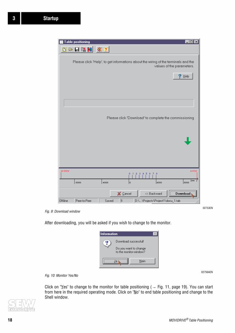
02753ENFig. 9: Download window
After downloading, you will be asked if you wish to change to the monitor.
02756AENFig. 10: Monitor Yes/No
Click on "Yes" to change to the monitor for table positioning (→ Fig. 11, page 19). You can startfrom here in the required operating mode. Click on "No" to end table positioning and change to theShell window.

MOVIDRIVE® Table Positioning 19
Startup 3
Repeated startup:If table positioning is run once startup is completed, the monitor for table positioning is displayed.
02755AENFig. 11:Table position monitorClick on <Startup>; the window for setting general parameters opens and you can begin startup.

20 MOVIDRIVE® Table Positioning
3 Startup
3.4 Parameters
When table positioning is started up, the following parameters are set automatically:
These parameters must not be changed after startup!
Parameter number Parameter Setting
100 Setpoint source Bipol./Fixed setpoint
101 Control signal source Terminals
600 Binary input DIØ1 Enable/Rapid stop
601 Binary input DIØ2 Reset
602 Binary input DIØ3 Reference cams
603 Binary input DIØ4 /LS CW
604 Binary input DIØ5 /LS CCW
610 Binary input DI1Ø IPOS input: mode Low
611 Binary input DI11 IPOS input: mode High
612 Binary input DI12 IPOS input: function 1
613 Binary input DI13 IPOS input: function 2
614 Binary input DI14 IPOS input: function 3
615 Binary input DI15 IPOS input: function 4
616 Binary input DI16 IPOS input: function 5
617 Binary input DI17 IPOS input: function 6
620 Binary output DOØ1 /Fault
621 Binary output DOØ2 Referenced
630 Binary output DO1Ø IPOS ouput: mode Low
631 Binary output DO11 IPOS ouput: mode High
632 Binary output DO12 IPOS ouput: value 1
633 Binary output DO13 IPOS ouput: value 2
634 Binary output DO14 IPOS ouput: value 4
635 Binary output DO15 IPOS ouput: value 8
636 Binary output DO16 IPOS ouput: value 16
637 Binary output DO17 IPOS ouput: position reached

MOVIDRIVE® Table Positioning 21
Startup 3
3.5 Starting up the Drive
After downloading the startup data, change to the monitor for the table positioning by clicking on"Yes". The operating mode is set via the binary inputs DI1Ø "Mode Low" und DI11 "Mode High".
3.5.1 Operating Modes
• Jog mode
– The drive is moved either in CW or CCW direction via the binary inputs DI13 and DI14.
– Two speeds, rapid and creep, can be selected via binary input DI15 for precision positioning.• Teach mode
– Each single position can be approached in jog mode, and then saved in teach mode. The tablelocation is selected via binary inputs DI13...DI17.
• Reference mode– A start command to binary input DI12 starts a reference travel operation. The reference travel
determines the reference point (machine zero point) for absolute positioning operations.
• Automatic operation
– Selection of the target position via the five binary inputs DI13...DI17 (binary code).– Reply from selected target position before travel via the five binary outputs DO12...DO16
(binary code).– Confirmation that the selected position has been reached via binary output DO17.
If the drive has not been referenced or if it must be re-referenced, you must select operating mode"Reference mode" using the DI1Ø "Mode Low" = "0" and DI11 "Mode High" = "1".
Without reference travel, selection of teach mode and automatic operation will be refused.
Operating mode Jog mode Teach mode Reference mode Automatic operation
DI1Ø: Mode Low "0" "1" "0" "1"
DI11: Mode High "0" "0" "1" "1"

22 MOVIDRIVE® Table Positioning
3 Startup
3.5.2 Reference Mode
• DI1Ø = "0" and DI11 = "1"
Reference position is determined with a reference travel to the reference cam. You can change themachine zero point with the reference offset set during startup, without changing the referencecam.These settings must be made according to the following formula:Machine zero point = reference position + reference offset.
02757AENFig. 12: Operating mode reference mode
• The correct reference travel type must be set. If this is not the case, you must repeat startup oftable positioning and set the required reference travel type.
• Apply "1" signals to DIØØ "/Controller inhibit" and DIØ1 "Enable/Rapid stop".• Start reference travel with a "1" signal to DI12 "Start Ref". The "1" signal must remain on DI12 for
the entire duration of reference travel.• When the drive reaches the reference position (DIØ3 "Reference cam" = "1"), it continues travel at
reference speed 2 and comes to a position-controlled standstill after leaving the reference point(DIØ3 "1" → "0"). Binary output DOØ2 "Axis referenced" is then set (= "1"-Signal). The "1" signalon DI12 can now be reset to "0".
The drive is now referenced and the required operating mode can be selected.

MOVIDRIVE® Table Positioning 23
Startup 3
3.5.3 Jog Mode
• DI1Ø = "0" and DI11 = "0"
By applying "1" signals to the binary inputs DI13 "Jog +" or DI14 "Jog -" in jog mode, you can manu-ally make the drive travel clockwise or counterclockwise. You can determine whether travel is atcreep speed (DI15 = "0") or rapid (DI15 = "1").
Jog mode is necessary for:– approaching new table positions which are to be saved in teach mode.
– for service, when the drive must travel independently of the system’s automatic mode.
02759AENFig. 13: Jog mode
24 MOVIDRIVE® Table Positioning
3 Startup
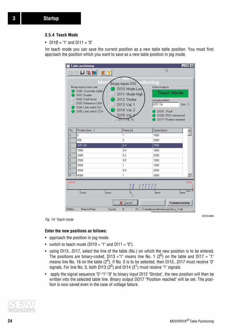
3.5.4 Teach Mode
• DI1Ø = "1" and DI11 = "0"
Im teach mode you can save the current position as a new table table position. You must firstapproach the position which you want to save as a new table position in jog mode.
02761AENFig. 14: Teach mode
Enter the new positions as follows:
• approach the position in jog mode.
• switch to teach mode (DI10 = "1" and DI11 = "0").• using DI13...DI17, select the line of the table (No.) on which the new position is to be entered.
The positions are binary-coded, DI13 ="1" means line No. 1 (20) on the table and DI17 = "1"means line No. 16 on the table (24). If No. 0 is to be selected, then DI13...DI17 must receive "0"signals. For line No. 3, both DI13 (20) and DI14 (21) must receive "1" signals.
• apply the signal sequence "0"-"1"-"0" to binary input DI12 "Strobe", the new position will then bewritten into the selected table line. Binary output DO17 "Position reached" will be set. The posi-tion is now saved even in the case of voltage failure.

MOVIDRIVE® Table Positioning 25
Startup 3
3.5.5 Automatic Operation
• DI1Ø = "1" and DI11 = "1"
In automatic operation you can select a table position via binary inputs DI13...DI17. The positionsare binary coded, DI13 ="1" means line No. 1 (20) on the table, DI17 = "1" means line No. 16 (24). IfNo. 0 is to be selected, then inputs DI13...DI17 must receive "0" signals.
Only lines from the table can be selected on which positions have been entered. If a line without aposition entry is selected, it will be ignored.
Applying a "1" signal to an binary input DI12 "Start Pos." starts the positioning travel operation. The"1" signal must remain on DI12 during the entire travel operation, otherwise the drive will stop.
02762AENFig. 15: Automatic opeartion
When the selected position has been reached, the drive comes to a position-controlled standstill.
The blue bar indicates the selected table line. The current position of the drive is displayed as anumerical value in the "Current Position" window and also graphically with a green arrow on thescale.

26 MOVIDRIVE® Table Positioning
4 Operation and Service
4 Operation and Service
4.1 Pulse Diagrams
The following requirements apply to the pulse diagrams:• DIØØ "/Controller inhibit" = "1" and
• DIØ1 "Enable/Rapid stop" = "1" signals.
Binary output DBØØ "/Brake" is set. The brake is released, the drive comes to a postion-controlledhalt.
4.1.1 Reference Mode and Automatic Operation
02763AENFig.16: Pulse diagram for reference mode and automatic operation
3000
1000 0
-100
0
Auto
mat
ic m
ode
activ
atedStar
t pos
ition
ing
trave
l
Tabl
e po
sitio
n no
. 5ap
proa
ched
Tabl
e po
sitio
n no
. 3ap
proa
ched
Tabl
e po
sitio
n no
. 8ap
proa
ched
Refe
renc
e po
int
appr
oach
ed
Star
t ref
eren
ce tr
avel
Refe
renc
e m
ode
activ
ated
n [1
/min
]
DIØ3
Refe
renc
e ca
m
DI1Ø
Mod
e lo
w
DI11
Mod
e hi
gh
DI12
Func
tion
1
DI13
Func
tion
2
DI14
Func
tion
3
DI15
Func
tion
4
DI16
Func
tion
6
DI17
Func
tion
7
DOØ2
Axis
refe
renc
ed
DO17
Posi
tion
appr
oach
ed
Hand
skak
e w
ith P
LC
Tabl
e po
sitio
n no
. 5se
lect
ed
Tabl
e po
sitio
n no
. 8se
lect
ed
Tabl
e po
stio
n no
. 3se
lect
ed

MOVIDRIVE® Table Positioning 27
Operation and Service 4
4.1.2 Jog Mode and Teach Mode
02768AENFig.17: Pulse diagram for jog mode and teach mode
n [1
/min
]20
0 20 0
-20
-200
DI1Ø
Mod
e Lo
w
DI11
Mod
e Hi
gh
DI12
Func
tion
1
DI13
Func
tion
2
DI14
Func
tion
3
DI15
Func
tion
4
DI16
Func
tion
6
DI17
Func
tion
7
DOØ2
Axis
refe
renc
ed
DO17
Posi
tion
appr
oach
ed
Save
new
pos
ition
Tabl
e po
sitio
n no
. 3se
lect
edTe
ach
mod
eac
tivat
ed
Rapi
d m
ode
activ
e
Jogg
ing
nega
tive
Jog
mod
eac
tivat
ed
Rapi
d m
ode
activ
e
Jogg
ing
posi
tive

28 MOVIDRIVE® Table Positioning
4 Operation and Service
4.2 Fault Information
The fault memory (P080) saves the last five fault messages (Fault t-0...t-4). The oldest of the faultmessages is deleted when more than five faults occur. When a fault occurs, the following data issaved:Fault occurred • status of the binary inputs/outputs • operational status of the inverter • inverterstatus • heat sink temperature • speed • output current • active current • unit utilization • DC linkvoltage • mains ON operating time • operating time (enabled) • parameter set • motor utilization.
Three responses are possible depending on the fault type; the inverter remains disabled in faultmode:
• Immediate switch-off:The unit cannot brake the drive any longer; the output stage becomes high-resistant when a faultoccurs and the brake is applied immediately (DBØØ "/Brake" = "0").
• Rapid stop:In this case, the motor is decelerated using the stop ramp t13/t23. When the stop speed is rea-ched, the brake is applied (DBØØ "/Brake" = "0"). The output stage becomes high-resistant whenthe brake has been applied (P732 / P735).
• Emergency stop:In this case the drive ramps down the emergency stop ramp t14/t24. After reaching the stopspeed, the brake is applied (DBØØ "/Brake" = "0"). The output stage becomes high-resistant whenthe brake has been applied (P732 / P735).
RESET: A fault message can be reset by:
• Power-down and power-up.Recommendation: observe a minimum switch-off time for the supply system contactor K11.
• Reset via binary input DI02. When table positioning is started, this input is assigned the "Reset"function.
• Open the Status window in the MOVITOOLS manager and activate the Reset button.
02771AENFig.18: Reset in MOVITOOLS
• Manual reset in Shell (P840 = "Yes" or [parameter] / [Manual reset])
• Manual reset on the DBG11A (pressing the <E> button when a fault occurs brings you directly toparameter P840)
Timeout active:
If the inverter is controlled via a communications interface (fieldbus, RS-485 or SBus) and if theinverter has been powered-up or down or a fault reset carried out, enable remains inactive until theinverter receives valid data again via the interface monitored by Timeout.

MOVIDRIVE® Table Positioning 29
Operation and Service 4
4.3 Fault Signals
The fault code or warning code is displayed in BCD-coded form according to the following displaysequence:
After reset or when the fault or warning code changes back to "0", the operating status is displayedagain.
List of faults:
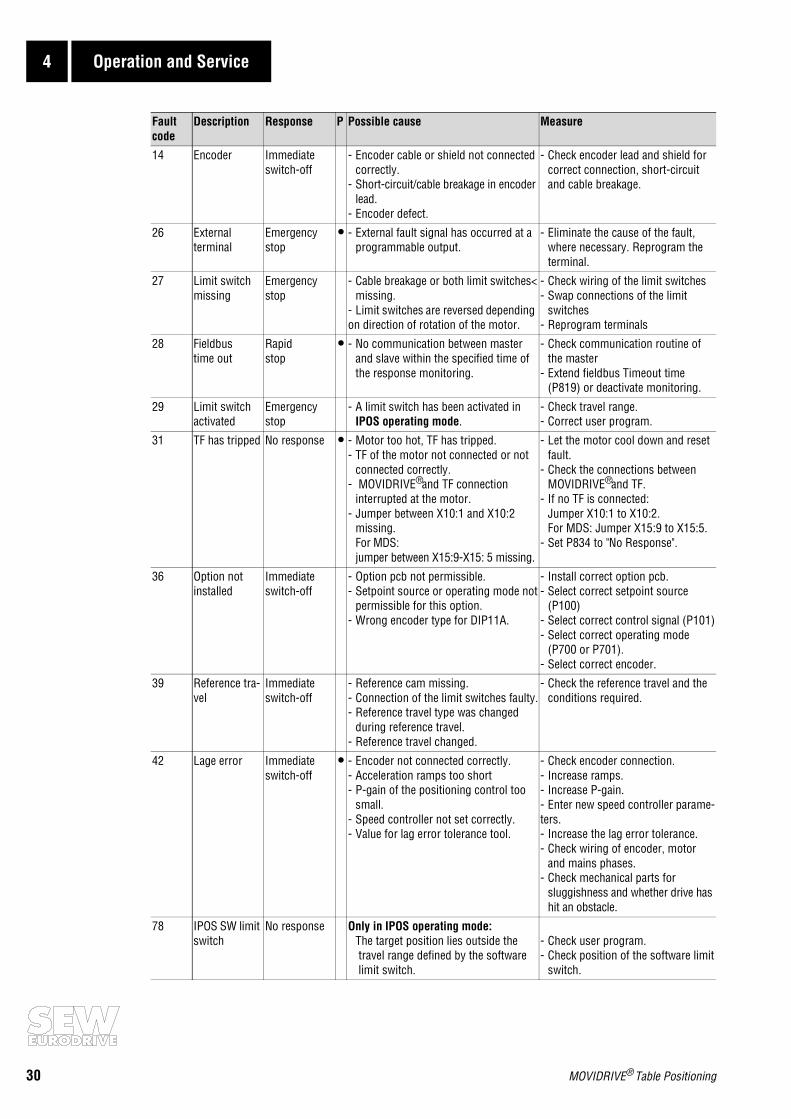
The following table contains an extract of the complete fault list (→ MOVIDRIVE® MD_60A Opera-ting Instructions). Only those faults are listed which specifially occur during table positioning.
One point in the "P" column means that the response can be programmed (P83_ Fault response).The fault response set in the factory is listed in the "Response" column.
01038AXXFig.19: Fault message
Flashing, approx. 1s
Display off, approx. 0.2s
Tens digits, approx. 1s
Display off, approx. 0.2s
Units digits, approx. 1s
Display off approx. 0.2s
Fault code
Description Response P Possible cause Measure
00 No fault -
07 DC link over-voltage
Immediate switch-off
DC link voltage. - Increase deceleration ramps.- Check connecting leads of the
brake resistor.- Check technical data of the brake resistor.
08 Speed moni-toring
Immediate switch-off
- Speed controller or current controller(in VFC mode without encoder) opera-
ting at the limit due to mechanical over-loading or phase failure on the mainsor motor.
- Encoder nicht connected correctly orwrong direction of rotation.
- With torque control, nmax is exceeded.
- Reduce load.- Increase delay time (501 or P503)- Check encoder connection, where
necessary, swap A/A and B/B.-Check voltage supply to encoders.- Check current limitation.- Increase ramps, if required.- Check motor leads and motors- Check mains phases.
30 MOVIDRIVE® Table Positioning
4 Operation and Service
14 Encoder Immediate switch-off
- Encoder cable or shield not connectedcorrectly.
- Short-circuit/cable breakage in encoderlead.
- Encoder defect.
- Check encoder lead and shield forcorrect connection, short-circuitand cable breakage.
26 Externalterminal
Emergencystop
• - External fault signal has occurred at aprogrammable output.
- Eliminate the cause of the fault,where necessary. Reprogram theterminal.
27 Limit switch missing
Emergencystop
- Cable breakage or both limit switches<missing.
- Limit switches are reversed depending on direction of rotation of the motor.
- Check wiring of the limit switches- Swap connections of the limit
switches - Reprogram terminals
28 Fieldbustime out
Rapidstop
• - No communication between master and slave within the specified time of
the response monitoring.
- Check communication routine ofthe master
- Extend fieldbus Timeout time(P819) or deactivate monitoring.
29 Limit switch activated
Emergencystop
- A limit switch has been activated inIPOS operating mode.
- Check travel range.- Correct user program.
31 TF has tripped No response • - Motor too hot, TF has tripped.- TF of the motor not connected or not
connected correctly.- MOVIDRIVE® and TF connection
interrupted at the motor.- Jumper between X10:1 and X10:2
missing.For MDS: jumper between X15:9-X15: 5 missing.
- Let the motor cool down and resetfault.
- Check the connections betweenMOVIDRIVE® and TF.
- If no TF is connected:Jumper X10:1 to X10:2.For MDS: Jumper X15:9 to X15:5.
- Set P834 to "No Response".
36 Option not installed
Immediate switch-off
- Option pcb not permissible.- Setpoint source or operating mode not
permissible for this option.- Wrong encoder type for DIP11A.
- Install correct option pcb.- Select correct setpoint source
(P100)- Select correct control signal (P101)- Select correct operating mode
(P700 or P701).- Select correct encoder.
39 Reference tra-vel
Immediate switch-off
- Reference cam missing.- Connection of the limit switches faulty.- Reference travel type was changed
during reference travel.- Reference travel changed.
- Check the reference travel and the conditions required.
42 Lage error Immediate switch-off
• - Encoder not connected correctly.- Acceleration ramps too short- P-gain of the positioning control too
small.- Speed controller not set correctly.- Value for lag error tolerance tool.
- Check encoder connection.- Increase ramps.- Increase P-gain.- Enter new speed controller parame-ters.- Increase the lag error tolerance.- Check wiring of encoder, motor
and mains phases.- Check mechanical parts for
sluggishness and whether drive hashit an obstacle.
78 IPOS SW limit switch
No response Only in IPOS operating mode:The target position lies outside the travel range defined by the software limit switch.
- Check user program.- Check position of the software limit
switch.
Fault code
Description Response P Possible cause Measure

MOVIDRIVE® Table Positioning 31
Operation and Service 4
92 DIP Arbeits-bereich
Emergency stop
Only with the DIP11A option :The drive has travelled beyond the opera-ting range of the absolute encoders. The setting of the DIP parameter for encoder type/operating range is possibly faulty.
Check position offset parameter, zero point offset.
93 DIP encoder Emergencystop
Only with the DIP11A option:The encoder reports a fault such as power failure for instance.- Encoder-DIP connecting lead
does not comply with therequirements (twisted-pair, shielded).
- Pulse frequency too high for the lengthof the lead.
- Permissible max. speed/acceleration of the encoder has been exceeded.
- Encoder defect.
- Check connection of the encoder.- Check the connection leads.
- Select the correct pulse frequency.- Reduce max. travel speed or ramp.- Change absolute encoder.
94 EEPROM Check sum
Immediate switch-off
The inverter electronics have been destroyed, possibly due to EMC distur-bances or faults.
Return unit for repair.
95 DIP plausibi-lity fault Emergency
stop
Only with DIP11A option:A plausible position could not be deter-mined.- Wrong encoder type set.- IPOS travel parameter set incorrectly.- Numerator/denominator factor set incorrectly.- Zero compensation carried out.- Encoder defect.
- Set correct encoder type.- Check IPOS travel parameter.- Check travel speed.- Correct numerator/denominator factor.- Reset after zero compensation.- Change absolute encoder.
Fault code
Description Response P Possible cause Measure

SEW-EURODRIVE right around the globe isyour competent partner in matters of power
transmission with manufacturing and assem-bly plants in most major industrial countries.
We are available, wherever you need us.Worldwide.
SEW-EURODRIVE GmbH & Co · P.O.Box 30 23 · D-76642 Bruchsal/GermanyTel. +49-7251-75-0 · Fax +49-7251-75-19 70 · Telex 7 822 391http://www.SEW-EURODRIVE.com · [email protected]