t ube screaming ultras in series along
TRANSCRIPT

Combo Pedal Wiring 1-2-3 by Playsforfun
There are many ways to wire up a pedal. Some of the folks around GuitarPCB.com like the way some of my “Combo
Builds” turned out and asked me to do a little tutorial. This is my usual way of planning it. Your results may vary.
Barry suggested a combo design based on “Stevie Ray’s style of playing using two Tube Screaming Ultras in series along
with the Emexar Micro Amp Style Boost circuit. This “3 in 1” Combo will work in a chain and add more versatility to other
dirt pedals. A small request right? I decided to take it on since I had the boards and parts on hand anyway. It may not
seem newbie friendly but boards in series are not a big deal. I did throw in a bass boost mod using a 3PDT (on-on) toggle
switch that boosts both boards simultaneously by changing the capacitor(s) C5 from the stock 220n to 470n.
I have used 2 of the boards known as Tube Screaming Ultra and the Micro Amp style boost in series. These boards offer
a clipping option for different overdrive sounds with a choice of silicon diodes or LEDs or letting the 4558 chip do the
driving by using a SPDT on-off-on. Of course these are socketed as well for any possibility in the future. I opted for
symmetrical clipping of the 1N914s and used 3mm red LEDs. See Tips, Tricks and Tutorials on the GuitarPCB.com site
about clipping options for your builds. I suggest you read them for maximum fun.
So let’s get to it. The circuit boards have been populated and the other components have been gathered together. You
can see jumpers added to the undersides of the Tube Screaming Ultra boards in place of C5 already in preparation for
the mod. A pair of 220n and a pair of 470n caps have been soldered to the 3PDT switch as the method chosen for the
mod. The wiring method was changed for this mod slightly as I got into it. Explanation is further down. 2 stereo jacks
were used just because that is what I had on hand. The enclosure is a 1590DD which will provide enough width for three
stomp switches comfortably.
What we want to ultimately achieve is a neatly wired enclosure without a lot of wasted wire that looks like it was done
professionally. Next we need to plan and visualize how to run the wires. There are many ways of doing the same thing.
Secondly, the more that can be done outside the constraint of the enclosure the better. So we pick which wire colors will
be used for what purpose and begin pre-wiring.

It’s good to have several colors of wire to work with. It helps if you use a color for a certain purpose. If you can just look
at a color and know what it does it helps tremendously. For example I chose white for the bypass signal from input,
through each 3PDT Wiring board and to the output. Violet was used for the board ins and outs. As you apply heat to the
wires while soldering you will notice that the insulation will melt back slightly. That is normal.
Once you apply solder it is good practice to push the wire through the hole while the solder is still molten so that the
insulation butts up close to the board. It looks great and should help eliminate shorts when packing everything into the
enclosure. You will feel secure as the undersides of the boards go out of site that no wires will cross and short.

Barry has done a tutorial on wiring a pot and using shrink boot for that pro look and also as an insulator against shorts to
the underside of the boards. It has become habit for me. Among the other great tutorials, look for it on the
GuitarPCB.com site under Tips, Tricks and Tutorials.
Pre-wiring is complete and we are ready to begin assembly. You may notice that some of the pots have only two wires
on them. That is because when a build schematic calls for lugs 2 and 3 for example, to be connected together I
personally place a jumper on the pot using a scrap piece of component lead. Then run a single wire instead of both to
the board. (Optional) You will also notice that changes were made to the jumpers from the C5 area on each of the Tube
Screaming Ultra boards. The green wires were removed from each ground pad of the C5s. And one yellow wire has

changed length. Each yellow wire from C5 will route to the toggle switch positions 2 and 8. You can see black wires have
been prepped to the center lug 5. Black is my normal ground color. This is an optional Mod. Newbie’s feel free to build
stock and you may skip over this mod discussed below.
Notice on the schematic that C5 goes to ground and realize that ground is ground, and then you can see that I don’t
have to use the C5 ground pads on the board, so I have options. The caps will go to ground at the switch connection. The
switch will do a double duty as it also helps route a ground chain to the 3PDT boards.
At this point I have planned how I think each wire will route. Wire length was planned accordingly trying to reduce
waste. A general length of 3.5 inches was used and there was very little waste. It is planned out how the 9v power wires
will reach each destination (the 3PDT Wiring Boards will come in handy). It is planned out how the grounding will be
wired, how the pot wires will sweep into their positions and how the wires will route from the stomp switch boards.
Next I mount all off-board components to the enclosure. Regardless of method it is important to test each circuit
individually and then transfer to the enclosure when satisfied. I measure each resistor, cap and diode with a DMM
before I solder it and I will triple check that I am doing things properly and give myself confidence that I won’t make a
mistake. Yes, mistakes happen, regardless of experience.
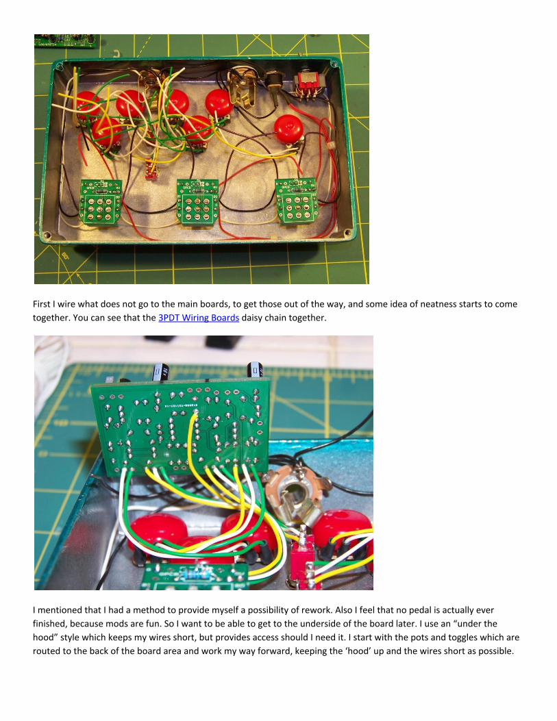
First I wire what does not go to the main boards, to get those out of the way, and some idea of neatness starts to come
together. You can see that the 3PDT Wiring Boards daisy chain together.
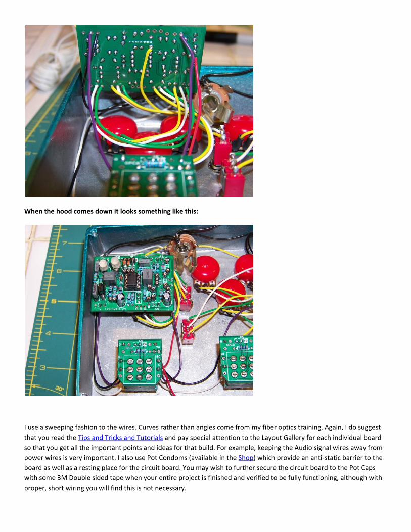
I mentioned that I had a method to provide myself a possibility of rework. Also I feel that no pedal is actually ever
finished, because mods are fun. So I want to be able to get to the underside of the board later. I use an “under the
hood” style which keeps my wires short, but provides access should I need it. I start with the pots and toggles which are
routed to the back of the board area and work my way forward, keeping the ‘hood’ up and the wires short as possible.
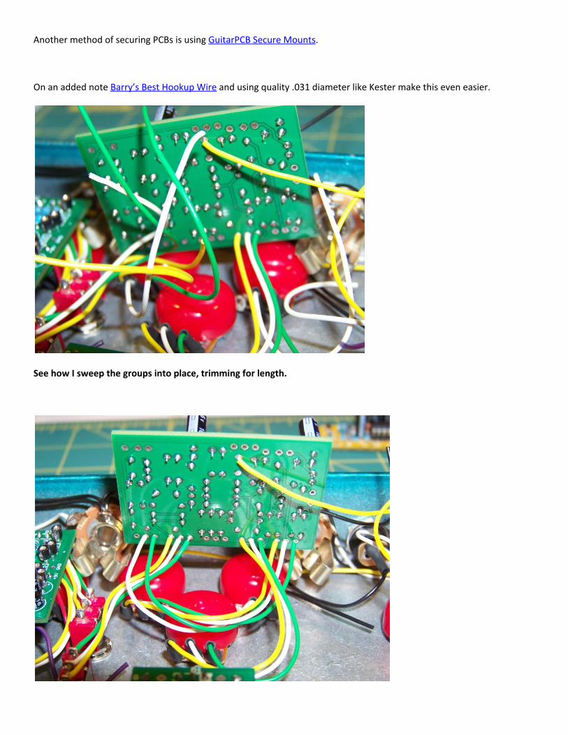
When the hood comes down it looks something like this:
I use a sweeping fashion to the wires. Curves rather than angles come from my fiber optics training. Again, I do suggest
that you read the Tips and Tricks and Tutorials and pay special attention to the Layout Gallery for each individual board
so that you get all the important points and ideas for that build. For example, keeping the Audio signal wires away from
power wires is very important. I also use Pot Condoms (available in the Shop) which provide an anti-static barrier to the
board as well as a resting place for the circuit board. You may wish to further secure the circuit board to the Pot Caps
with some 3M Double sided tape when your entire project is finished and verified to be fully functioning, although with
proper, short wiring you will find this is not necessary.
Another method of securing PCBs is using GuitarPCB Secure Mounts.
On an added note Barry’s Best Hookup Wire and using quality .031 diameter like Kester make this even easier.
See how I sweep the groups into place, trimming for length.

Keeping wires short but allowing for the hood up possibility for future mods.
Hood up.
Hood down. See how a lot of that wiring spaghetti is disappearing?

Finished!
Wires routed for neatness and effectiveness. A few wires shortened for looks and ground loop removed.
As an added note I cannot stress how much using the 3PDT Wiring Boards makes this a breeze. And there you have it.
Here is another one: CTO (Colortone Overdrive) + Stage 357 – What a fantastic & versatile combo!
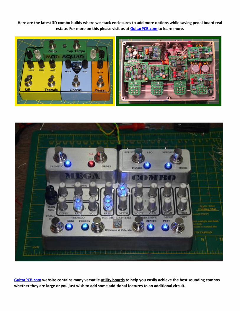
Here are the latest 3D combo builds where we stack enclosures to add more options while saving pedal board real
estate. For more on this please visit us at GuitarPCB.com to learn more.
GuitarPCB.com website contains many versatile utility boards to help you easily achieve the best sounding combos
whether they are large or you just wish to add some additional features to an additional circuit.

GuitarPCB offers 3PDT wiring boards, DPDT wiring boards, Easy Order Switching boards in both 4PDT and 3PDT Toggle
versions, 2 Knob Job board (instantly change any potentiometer setting and back), our famous Tone TwEQ active 3
band EQ (can be added to any circuit in multiple ways), our Roto-Tone 4 option rotary switch and many more.
Here are a few examples:
See below what you can do using our famous Tone TwEQ
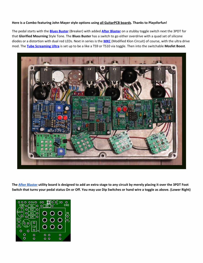
Here is a Combo featuring John Mayer style options using all GuitarPCB boards. Thanks to Playsforfun!
The pedal starts with the Blues Buster (Breaker) with added After Blaster on a stubby toggle switch next the 3PDT for
that Glorified Mourning Style Tone. The Blues Buster has a switch to go either overdrive with a quad set of silicone
diodes or a distortion with dual red LEDs. Next in series is the MKC (Modified Klon Circuit) of course, with the ultra drive
mod. The Tube Screaming Ultra is set up to be a like a TS9 or TS10 via toggle. Then into the switchable Mosfet Boost.
The After Blaster utility board is designed to add an extra stage to any circuit by merely placing it over the 3PDT Foot
Switch that turns your pedal status On or Off. You may use Dip Switches or hand wire a toggle as above. (Lower Right)
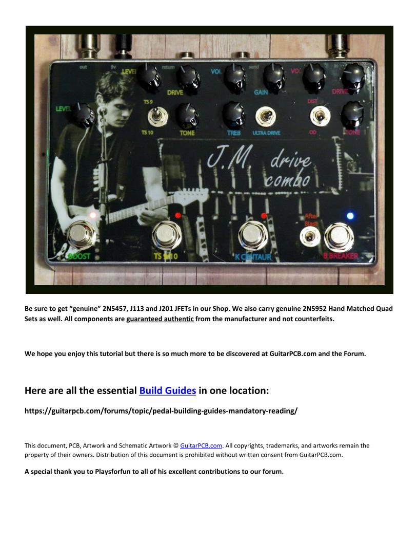
Be sure to get “genuine” 2N5457, J113 and J201 JFETs in our Shop. We also carry genuine 2N5952 Hand Matched Quad
Sets as well. All components are guaranteed authentic from the manufacturer and not counterfeits.
We hope you enjoy this tutorial but there is so much more to be discovered at GuitarPCB.com and the Forum.
Here are all the essential Build Guides in one location:
https://guitarpcb.com/forums/topic/pedal-building-guides-mandatory-reading/
This document, PCB, Artwork and Schematic Artwork © GuitarPCB.com. All copyrights, trademarks, and artworks remain the
property of their owners. Distribution of this document is prohibited without written consent from GuitarPCB.com.
A special thank you to Playsforfun to all of his excellent contributions to our forum.