t2™ tibial nailing system - · pdf fileaccording to the fracture type, the system offers...
TRANSCRIPT

T2™ Tibial Nailing System
Operative Technique
2 3
Contributing Surgeons :
Prof. Dr. med. Volker BührenChief of Surgical ServicesMedical Director of Murnau Trauma CenterMurnau, Germany
Kyle F. Dickson, M. D.Director of Surgery & Chief of OrthopaedicsCharity HospitalAssociate Professor & Director of Orthopaedic TraumaTulane UniversityAssistant Clinical ProfessorLouisiana State UniversityNew Orleans, LouisianaUSA
Paul Tornetta, III, M. D.Director of Orthopaedic Trauma, Boston Medical CenterProfessor and Vice Chairman Department of Orthopaedic SurgeryBoston University School of MedicineBoston, MassachusettsUSA
This publication sets forth detailed recommended procedures for using Stryker Trauma devices and instruments.
It offers guidance that you should heed, but, as with any such technical guide, each surgeon must considerthe particular needs of each patient and make appropriate adjustments when and as required.
A workshop training is required prior to first surgery.
Tibial Nailing System
2 3
1. Introduction
1.1. Implant Features
1.2. Instrument Features
1.3. References
2. Indications
3. Pre-operative Planning
4. Operative Technique
4.1. Patient Positioning Options and Reduction
4.2. Incision
4.3. Entry Point
4.4. Unreamed Technique
4.5. Reamed Technique
4.6. Nail Selection
4.7. Nail Insertion
4.8. Guided Locking Mode (via Target Device)
4.9. Static Locking Mode
4.10. Freehand Distal Locking
4.11. End Cap Insertion
4.12. Dynamic Locking Mode
4.13. Apposition /Compression Locking Mode
4.14. Advanced Locking Mode
4.15. Nail Removal
4.16 Blocking Screw Technique (optional)
Ordering Information – Implants
Ordering Information – Instruments
4
4
6
6
7
7
8
8
8
8
9
9
10
10
13
14
16
17
18
18
20
21
22
24
28
Contents

4 5
1. Introduction
The T2™ Tibial Nailing System represents the latest and most com-prehensive development of the original intramedullary principles presented by Prof. Gerhard Küntscher in 1940.Stryker Trauma has created a new generation locking nail system, bringing together all the capabilities and benefits of separate nailing systems to create a single, integrated surgical resource for fixation of long bone fractures.
The T2™ Tibial Nailing System offers the competitive advantages of:
• Not limiting the approach to a certain nailing technique.
• Accommodating reamed or unreamed procedures.
• Providing locking options for all types of fractures, plus the Advanced Locking Mode for increased rotational stability.
Through the development of a com-mon, streamlined and intuitive surgical approach, both in principle and in detail, the T2™ Tibial Nailing System offers significantly increased speed and functionality for the treatment of fractures as well as sim-plifying the training requirements for all personnel involved.
1.1. Implant Features
The T2™ Tibial Nailing System is the realization of superior biome-chanical intramedullary stabilization using small caliber, strong cannulated implants for internal fixation of long bones.
According to the fracture type, the system offers the option of different locking modes. In addition to static locking, a controlled dynamization with rotational stability is optional.
In some indications, a controlled apposition/compression of bone fragments can be applied by introducing a Compression Screw from the top of the nail. To further increase rotational stability, the nail can be locked statically after using the controlled dynamization and apposition/compression option.
The Compression Screw is pushed against the proximal Partially Threaded Locking Screw that has been placed in the oblong hole, drawing the distal segment towards the fracture site. In stable fractures, this has the biomechanical advantage of creating active circumferential compression to the fracture site, transferring axial load to the bone, and reducing the function of the nail as a load bearing device (1).
This ability to transfer load back to the bone can reduce the incidence of implant failure secondary to fatigue. Typical statically locked nails function as load bearing devices and failure rates in excess of 20 % have been reported (2).
The beneficial effect of apposition/compression in treating long bone fractures in cases involving transverse and short oblique fractures that are axially stable is well documented (3, 4).In addition to the T2™ Standard Tibial Nail that features options to address very proximal and very distal fractures as well as the advanced compression feature, there are two additional Tibial Nail designs avail-able on a special order basis that address specific surgical indications:
The T2™ Distal Tibial Nail, avail-able in 10mm diameter only, may be used for very distal fractures * . As with the Standard Nail, an oblong hole is located in the proximal third of the nail for optional controlled
Introduction
dynamization and apposition/compression. Compared to the Stand-ard Nail, the oblong hole is 7mm further distal, ending just above the Herzog 10 ° bend. The Distal Tibial Nail has 2 distal locking holes at 5mm and 13mm centered from the distal tip.
The T2™ Proximal Tibial Nail may also be used for very proximal and very distal fractures. The Proxi-mal Tibial Nail does not feature an oblong hole for optional controlled dynamization and apposition/com-pression. The location of the 3 distal locking holes is the same as the Standard Nail.
Note: All three nail designs feature the distal most hole centered at 5mm from the distal tip to better address hard to reach distal fractures.
Common 5mm cortical screws simplify the surgical procedure and promote a minimally invasive approach. Fully Threaded Locking Screws are available for regular locking procedures. Partially Thread-ed Locking Screws (Shaft Screws) are designed for use if apposition/compression is applied.
Note: The 8mm T2™ Tibial Nail can only be locked distally with 4mm Fully Threaded screws. As with all diameters of T2™ Tibial Nails, the proximal screws are 5mm.
One common Compression Screw to close the fracture site, and End Caps in eight sizes are available to provide a
“best fit” for every indication.
All implants in the T2™ Tibial Nail-ing System are gun-drilled and made of Type II anodized titanium alloy (Ti6AL4V) for enhanced biomechanical and biomedical per-formance.
* The Distal Tibial Nail is not cleared for primary ankle arthrodesis in the U. S.
4 5
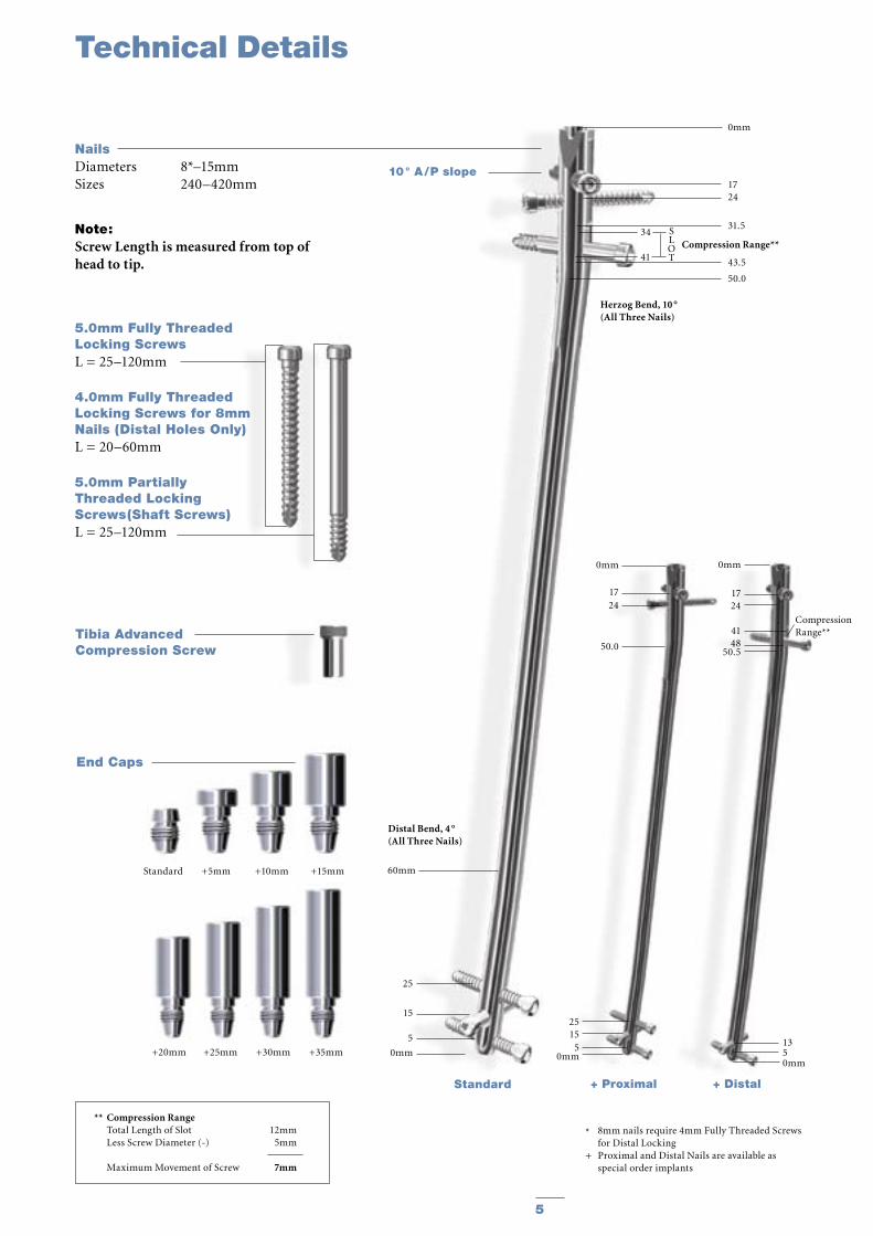
NailsDiameters 8*–15mmSizes 240–420mm
10 ° A / P slope
Compression Range**34
41
Herzog Bend, 10 °(All Three Nails)
1350mm
+ Distal
0mm
1724 4148
50.5
CompressionRange**
0mm
1724
50.0
2515
50mm
25
15
5
0mm
Distal Bend, 4 °(All Three Nails)
60mm
0mm
1724
31.5
43.5
50.0
SLOT
+ ProximalStandard
Technical Details
5.0mm Fully ThreadedLocking ScrewsL = 25–120mm
4.0mm Fully ThreadedLocking Screws for 8mm Nails (Distal Holes Only)L = 20–60mm
5.0mm Partially Threaded Locking Screws(Shaft Screws)L = 25–120mm
Tibia AdvancedCompression Screw
* 8mm nails require 4mm Fully Threaded Screws for Distal Locking+ Proximal and Distal Nails are available as special order implants
Note: Screw Length is measured from top of head to tip.
End Caps
Standard +5mm +10mm +15mm
** Compression Range Total Length of Slot 12mm Less Screw Diameter (-) 5mm
Maximum Movement of Screw 7mm
+20mm +25mm +30mm +35mm

6 7
1.2. Instrument Features
The major advantage of the instru-ment system is a breakthrough in the integration of the instrument platform which can be used not only for the complete T2™ Nailing System, but will be the platform for all future nailing systems, thereby reducing complexity and inventory.
The innovative instrument platform offers advanced precision and usability, and features ergonomically styled tar-geting devices.
In addition to the advanced precision and usability, the instruments are both color, number and symbol coded to indicate its usage during the surgical procedure.
Color and number coding indicates the step during the procedure in which the instrument is used. This color code system is marked on the trays to easily identify the correct instrument.
1. T. E. Richardson, M. Voor, D. Seligson, Fracture Site Compression and Motion with Three Types of Intramedullary Fixation of the Femur, Osteosynthese International (1998), 6: 261-264.
2. Hutson et al., Mechanical Failures of Intramedullary Tibial Nails Applied without Reaming, Clin. Orthop. (1995), 315: 129-137.
3. M. E. Müller, et al. Manual of Internal Fixation, Springer-Verlag, Berlin.
Features
1.3. References
4. O. Gonschorek, G. O. Hofmann, V. Bühren, Interlocking Compression Nailing: a Report on 402 Applications, Arch. Orthop. Trauma Surg (1998), 117: 430-437.
5. Mehdi Mousavi, et al., Pressure Changes During Reaming with Different Parameters and Reamer Designs, Clinical Orthopaedics and Related Research, Number 373, pp. 295-303, 2000.
6. Tibial Portal Placement: The Radiographic Correlate of the Anatomic Safe Zone, Timothy McConnell, Paul Tornetta III, John Tizley, David Casey, Journal of Orthopaedic Trauma, Vol. 15, No. 3, pp. 207-209
7. Stedtfeld H.-W., Rapke C., Jurowich B. Besonder-heiten der Verriegelungsnagelung proximaler Tibiaschaftfrakturen. Osteosynthese International 1995; 4: 264-270.
8. Stedtfeld H.-W. Die transmedulläre Stützschraube. Osteosynthese International (Suppl 1) 2000; 8: 170-172.
Step Color NumberOpening Red 1Reduction Brown 2Nail Introduction Green 3Guided Locking Light Blue 4Freehand Locking Dark Blue 5
Drills
Drills feature color-coded rings:
4.2mm = GreenFor 5.0mm Fully Threaded Locking Screws and for the second cortex when using 5.0mm Partially Threaded Locking Screws (Shaft Screws).
5.0mm = BlackFor the first cortex when using 5.0mm Partially Threaded Locking Screws (Shaft Screws).
3.5mm = OrangeFor 4.0mm Fully Threaded Locking Screws for the distal holes only of the 8mm Tibial Nail.
Symbol coding on the instruments indicates the type of procedure, and must not be mixed.
Symbol
Square = Long instruments, Femur
Triangular = Short instruments, Tibia and Humerus

6 7
2. Indications
The T2™ Tibial Nailing System is indicated for:
• Open or closed shaft fractures with a very proximal and very distal extent in which locking screw fixation can be obtained• Multi-fragment fractures• Segmental fractures• Proximal or distal non-unions• Proximal or distal mal-unions• Pseudarthrosis• Corrective osteotomies• Pathologic and impending pathologic fractures• Tumor resections• Comminuted fractures with or without bone loss• Primary ankle arthrodesis *.
3. Pre-Operative Planning
An X-Ray Template (1806-0000 for Standard and Proximal nails, 1806-0001 for Distal nails) is available for pre-operative planning.
Thorough evaluation of preoperative radiographs of the affected extremity is critical. Careful radiographic exami-nation can prevent intra-operative complications.
For standard mid-shaft fractures, the proper nail length should extend from just below the Tibial Plateau at the appropriate medio-lateral position to just proximal to the Epiphyseal Scar of the ankle joint.
This allows the surgeon to consider the apposition/compression feature of the T2™ Standard Tibial Nail and T2™ Distal Tibial Nail knowing that 7mm of active apposition/compression is possible, prior to determining the final length of the implant. If appo-sition/compression is planned, the nail should be at least 7mm shorter.
Note: Check with local representative regarding availability of sizes and nail types.
* This indication is not cleared for use in the U. S.
Indications

8 9
Fig. 1
4. Operative Technique
4.1. Patient Positioning Options and Reduction
a) The patient is placed in the supine position on a radiolucent fracture table and the leg is hyperflexed on the table with the aid of a leg holder, or b) The leg is free draped and hung over the edge of the table (Fig. 1).
The knee is flexed to >90°. A triangle may be used under the knee to accom-modate flexion intra-operatively. It is important that the knee rest is placed under the posterior aspect of the lower thigh in order to reduce the risk of vascular compression and of pushing the proximal fragment of the tibia anteriorly.Anatomical reduction can be achieved by internal or external rotation of the fracture and by traction, adduction or abduction, and must be confirmed under image intensification. Draping must leave the knee and the distal end of the leg exposed.
4.2. Incision
Based on radiological image, a para-tendenous incision is made from the patella extending down approximately 1.5–4cm in preparation of nail inser-tion. The Patellar Tendon may be retracted laterally or split at the junc-tion of the medial third, and lateral two-thirds of the Patellar Ligament. This determines the entry point (Fig. 2).
4.3. Entry Point
The medullary canal is opened through a superolateral plateau entry portal. The center point of the portal is located slightly medial to the lateral tibial spine as visualized on the A/P radiograph and immediately adjacent and anterior to the anterior articular margin as visualized on the true lat-eral radiograph. It is located lateral to the midline of the tibia by an average of 6 percent of the tibial plateau width. Radiographic confirmation of this area is essential to prevent damage to the intra-articular structure during portal placement and nail insertion (Fig. 3). The opening should be directed with a
Fig. 3
Fig. 5Fig. 4
Fig. 2
Operative Technique
central orientation in relation to the medullary canal. After penetrating the cor-tex with the 3×285mm K-Wire (1806-0050S), the Ø10mm Rigid Reamer (1806-2010) or the “special order” Ø11.5 Rigid Reamer (1806-2011) is used to access the medullary canal (Fig. 4). Alternatively, to penetrate the cortex, the Ø10mm Straight (1806-0045), “special order” Ø11.5mm Straight (1806-0047), or Curved (1806-0040) Awl may be used (Fig. 5).
Note: A more distal entry point may result in damage to the posterior cortex during nail insertion.
Note: Guiding the Rigid Reamer over the K-Wire prior to K-Wire insertion within the Proximal Tibia will help to keep it straight while guiding the opening in-strument centrally towards the canal. Do not use bent K-Wires.
Note:During opening the entry portal with the Awl, dense cortex may block the tip of the Awl. An Awl Plug (1806-0032) can be inserted through the Awl to avoid penetration of bone debris into the cannulation of the Awl shaft.
L M

8 9
Fig. 8
4.4. Unreamed Technique
If an unreamed technique is prefer-red, the 3×800mm Smooth Tip Guide Wire (1806-0090S) is passed through the fracture site using the Guide Wire Handle (1806-0095 and 1806-0096) (Fig. 6). The Universal Rod (1806-0110) with Reduction Spoon (1806-0125), or the Reduction Tip (special order 1806-0120), may be used as a fracture reduction tool to facilitate Guide Wire insertion (Fig. 7), and as a “sound” to help determine the diameter of the medullary canal. The Universal Rod is 9mm diameter. Internal rotation during insertion will aid in passing the Guide Wire down the tibial shaft. The Guide Wire should lie in the center of the metaph-ysis and the diaphysis in both the A/P and Lateral views to avoid offset posi-tioning of the nail. The Guide Wire handle is removed leaving the Guide Wire in place.
4.5. Reamed Technique
For reamed techniques, the 3 × 800mm Ball Tip Guide Wire (1806-0080S) is inserted through the fracture site. Except for the 8mm Tibial Nails, use of the Ball Tip Guide Wire does not require a Guide Wire exchange. The Universal Rod with Reduction Spoon or Reduction Tip may be used as a frac-ture reduction tool to facilitate Guide Wire insertion through the fracture site (see Fig. 7).
Note: The Ball Tip at the end of the Guide Wire will stop the reamer head.
Reaming (Fig. 8) is commenced in 0.5mm increments until cortical contact is appreciated. Final reaming should be 1mm –1.5mm larger than the diameter of the nail to be used.
Note: The proximal diameter of the 8mm –11mm diameter nails is 11.5mm. Additional proximal meta-physeal reaming may be required to facilitate nail insertion. Nail sizes 12–15mm have a constant diameter.
Note: 8mm Tibial Nails cannot be inserted over the 3×800mm Ball Tip Guide Wire (1806-0080S). The Ball Tip Guide wire must be exchanged for the 3×800mm Smooth Tip Guide Wire (1806-0090S) prior to nail insertion.
Bixcut™ Reamer
The complete range of Bixcut™ ream-ers is available with either modular or fixed heads. The optimized cutting flute geometry is designed to reduce intramedullary pressure and tempera-ture. This is achieved by the forward and side cutting face combination of the reamer blades. The large clear-ance rate resulting from the reduced number of reamer blades, coupled with the reduced length of the reamer head, relieves the intramedullary pres-sure and provides efficient removal of reamed material. See pages 30–31 for additional Bixcut™ Reamer system details.
Fig. 6
Fig. 7
Operative Technique

10 11
End of Guide Wire Rulerequals Measurement Reference
Fig. 10
Hole Positions
Fig. 9
Compression Slot1. Dynamic2. Static 3. Dynamic - > Distal Nail Only
> Standard Nail OnlyOblique Holes-Static
Proximal Distal
Length
Hole Positions
Strike Plate
Nail Holding Screw
Nail Handle
Targeting Arm
Fig. 11
4.6. Nail Selection
DiameterThe diameter of the selected nail should be 1–1.5mm smaller than that of the last reamer used.
LengthThe X-Ray Ruler (1806-0010) may be used to determine nail diameter and length. The X-Ray Ruler may also be used as a guide to help determine final Locking Screw positions (Fig. 9).
Note: X-Ray Ruler also features Distal Hole Configurations
Alternatively, nail length may be deter-mined by measuring the remaining length of the Guide Wire. The Guide
Wire Ruler (1806-0020) is placed on the Guide Wire and the correct nail length is read at the end of the Guide Wire on the Guide Wire Ruler (Fig. 10).
Note: If the fracture is suitable for appo-sition/compression, the implant selected should be 7–12mm shorter than measured to help avoid migra-tion of the nail beyond the insertion site.
The Guide Wire Ruler is calibrated for 800 and 1000mm Guidewires with markings for the Tibia, Femur and Humerus.
Upon completion of reaming, the appropriate size nail is ready for insertion.
4.7. Nail Insertion
The selected nail is assembled onto the Tibial Target Device (1806-1000) with the Tibial Nail Holding Screw (1806-0370) (Fig. 11). Securely tighten the Nail Holding Screw with the Insertion Wrench (1806-0135) so that it does not loosen during nail insertion.
To attach the Nail Handle to the Targeting Arm, turn the Quick-Lock Ring on the Targeting Arm clockwise. Triangles on the Quick-Lock Ring and the Targeting Arm indicate the cor-rect position to attach the Nail Handle when both triangles are in line with each other.
Operative Technique
10 11
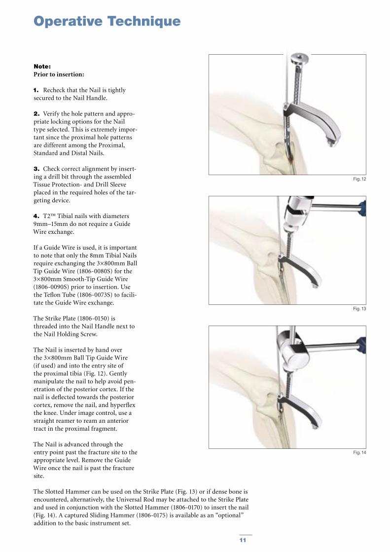
Note: Prior to insertion:
1. Recheck that the Nail is tightly secured to the Nail Handle.
2. Verify the hole pattern and appro-priate locking options for the Nail type selected. This is extremely impor-tant since the proximal hole patterns are different among the Proximal, Standard and Distal Nails.
3. Check correct alignment by insert-ing a drill bit through the assembled Tissue Protection- and Drill Sleeve placed in the required holes of the tar-geting device.
4. T2™ Tibial nails with diameters 9mm–15mm do not require a Guide Wire exchange.
If a Guide Wire is used, it is important to note that only the 8mm Tibial Nails require exchanging the 3×800mm Ball Tip Guide Wire (1806-0080S) for the 3×800mm Smooth-Tip Guide Wire (1806-0090S) prior to insertion. Use the Teflon Tube (1806-0073S) to facili-tate the Guide Wire exchange.
The Strike Plate (1806-0150) is threaded into the Nail Handle next to the Nail Holding Screw.
The Nail is inserted by hand over the 3×800mm Ball Tip Guide Wire (if used) and into the entry site of the proximal tibia (Fig. 12). Gently manipulate the nail to help avoid pen-etration of the posterior cortex. If the nail is deflected towards the posterior cortex, remove the nail, and hyperflex the knee. Under image control, use a straight reamer to ream an anterior tract in the proximal fragment.
The Nail is advanced through the entry point past the fracture site to the appropriate level. Remove the Guide Wire once the nail is past the fracture site.
Fig. 13
Fig. 14
Fig. 12
The Slotted Hammer can be used on the Strike Plate (Fig. 13) or if dense bone is encountered, alternatively, the Universal Rod may be attached to the Strike Plate and used in conjunction with the Slotted Hammer (1806-0170) to insert the nail (Fig. 14). A captured Sliding Hammer (1806-0175) is available as an “optional” addition to the basic instrument set.
Operative Technique
12 13
Fig. 15 Fig. 16
12mm compression slot allows 7mm of compression(Standard and Distal Nails Only)
Fig. 16A
2mm
7mm
12mm
Static
Dynamic
Apposition/Compression
Fig. 17
Turn silver Quick-Lock Ring Clockwise
Bring Targeting Arm up to Nail Handle
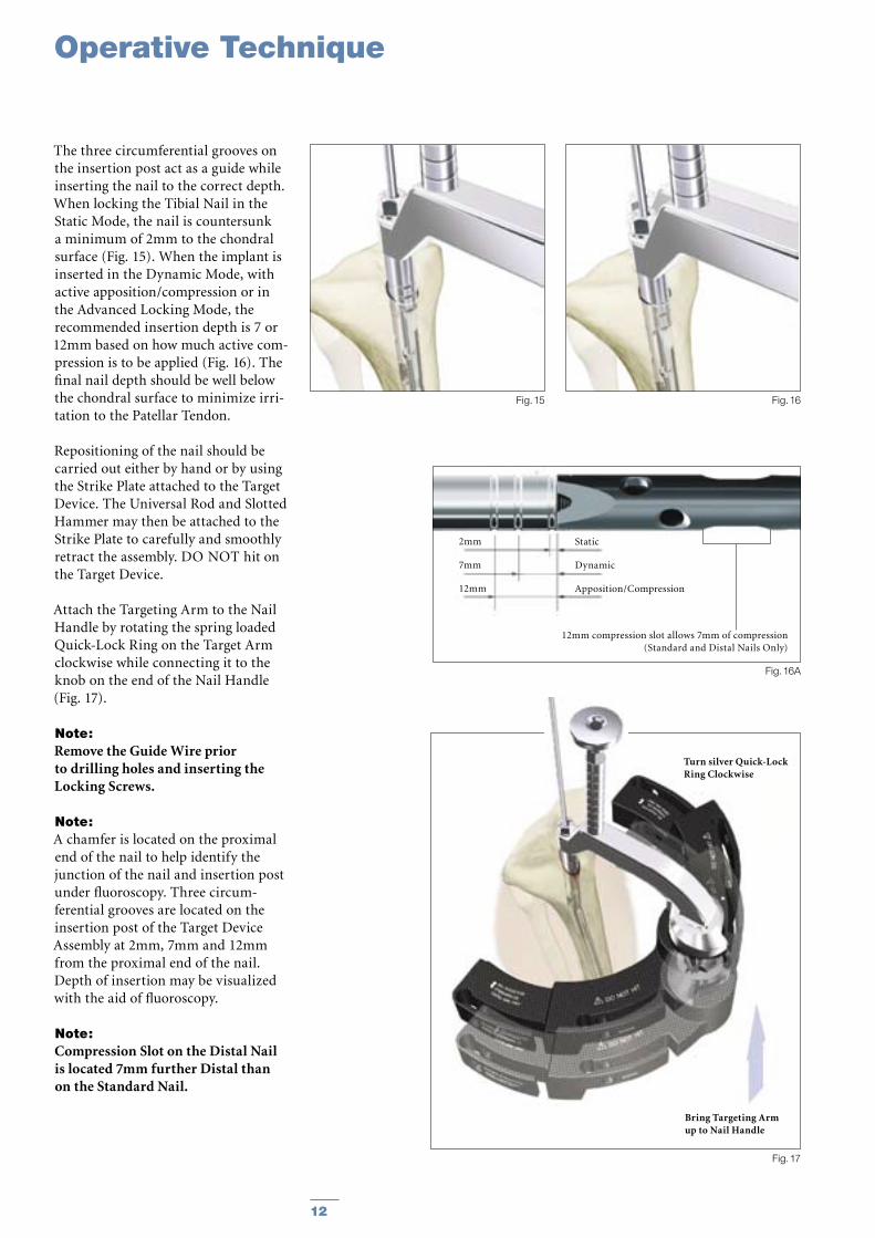
The three circumferential grooves on the insertion post act as a guide while inserting the nail to the correct depth. When locking the Tibial Nail in the Static Mode, the nail is countersunk a minimum of 2mm to the chondral surface (Fig. 15). When the implant is inserted in the Dynamic Mode, with active apposition/compression or in the Advanced Locking Mode, the recommended insertion depth is 7 or 12mm based on how much active com-pression is to be applied (Fig. 16). The final nail depth should be well below the chondral surface to minimize irri-tation to the Patellar Tendon.
Repositioning of the nail should be carried out either by hand or by using the Strike Plate attached to the Target Device. The Universal Rod and Slotted Hammer may then be attached to the Strike Plate to carefully and smoothly retract the assembly. DO NOT hit on the Target Device.
Attach the Targeting Arm to the Nail Handle by rotating the spring loaded Quick-Lock Ring on the Target Arm clockwise while connecting it to the knob on the end of the Nail Handle (Fig. 17).
Note: Remove the Guide Wire prior to drilling holes and inserting the Locking Screws.
Note: A chamfer is located on the proximal end of the nail to help identify the junction of the nail and insertion post under fluoroscopy. Three circum-ferential grooves are located on the insertion post of the Target Device Assembly at 2mm, 7mm and 12mm from the proximal end of the nail. Depth of insertion may be visualized with the aid of fluoroscopy.
Note: Compression Slot on the Distal Nail is located 7mm further Distal than on the Standard Nail.
Operative Technique
12 13
4.8. Guided Locking Mode (via Target Device)
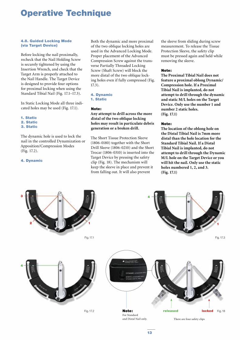
Before locking the nail proximally, recheck that the Nail Holding Screw is securely tightened by using the Insertion Wrench, and check that the Target Arm is properly attached to the Nail Handle. The Target Device is designed to provide four options for proximal locking when using the Standard Tibial Nail (Fig. 17.1–17.3).
In Static Locking Mode all three indi-cated holes may be used (Fig. 17.1).
1. Static2. Static3. Static
The dynamic hole is used to lock the nail in the controlled Dynamization or Apposition/Compression Modes (Fig. 17.2).
4. Dynamic
Both the dynamic and more proximal of the two oblique locking holes are used in the Advanced Locking Mode. Proper placement of the Advanced Compression Screw against the trans-verse Partially Threaded Locking Screw (Shaft Screw) will block the more distal of the two oblique lock-ing holes even if fully compressed (Fig. 17.3).
4. Dynamic1. Static
Note: Any attempt to drill across the more distal of the two oblique locking holes may result in particulate debris generation or a broken drill.
The Short Tissue Protection Sleeve (1806-0180) together with the Short Drill Sleeve (1806-0210) and the Short Trocar (1806-0310) is inserted into the Target Device by pressing the safety clip (Fig. 18). The mechanism will keep the sleeve in place and prevent it from falling out. It will also prevent
the sleeve from sliding during screw measurement. To release the Tissue Protection Sleeve, the safety clip must be pressed again and held while removing the sleeve.
Note: The Proximal Tibial Nail does not feature a proximal oblong Dynamic/Compression hole. If a Proximal Tibial Nail is implanted, do not attempt to drill through the dynamic and static M/L holes on the Target Device. Only use the number 1 and number 2 static holes. (Fig. 17.1)
Note: The location of the oblong hole on the Distal Tibial Nail is 7mm more distal than the hole location for the Standard Tibial Nail. If a Distal Tibial Nail is implanted, do not attempt to drill through the Dynamic M/L hole on the Target Device or you will hit the nail. Only use the static holes numbered 1, 2, and 3. (Fig. 17.1)
Fig. 17.2 Fig. 18
There are four safety clips
Note: For Standard
and Distal Nail only.
4
Fig. 17.1 Fig. 17.3
3
2 1
4
1
released locked
Operative Technique

14 15
Fig. 19
Fig. 21
50mm
50mm
Fig. 20
4.9. Static Locking Mode
For static locking of the Standard Tibial Nail, both proximal oblique screws and the M/L Locking Screw may be used. In highly unstable, com-minuted fractures the M/L screw is placed in the static position of the oblong hole. This may further improve stability of the proximal fragment.
If secondary dynamization is planned, the M/L screw may be inserted in the dynamic position of the oblong hole on the Target Device. This allows con-trolled dynamization of the fracture in cases of delayed union after removal of the proximal oblique screws.
Note: If secondary dynamization is used with the Distal Tibial Nail, the M/L screw has to be inserted through the distal most part of of the oblong hole the Target Device. (The oblong hole on the Distal Tibial Nail is 7mm more distal than on the Standard Tibial Nail).
Always start with the most distal oblique Fully Threaded Locking Screw. The Short Tissue Protection Sleeve (assembled with the short Drill Sleeve and Trocar) is positioned through the static locking hole on the Target Device. A small skin incision is made, and while pressing the safety clip, the Tissue Protection Sleeve is pushed through until it is in contact with the anterior cortex (Fig. 19).
The Short Trocar is removed, with the Tissue Protection Sleeve and Drill Sleeve remaining in position.
Operative Technique
14 15
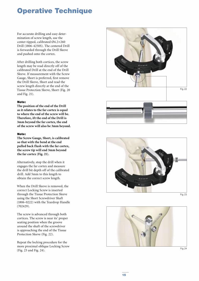
For accurate drilling and easy deter-mination of screw length, use the center-tipped, calibrated Ø4.2×260 Drill (1806-4250S). The centered Drill is forwarded through the Drill Sleeve and pushed onto the cortex.
After drilling both cortices, the screw length may be read directly off of the calibrated Drill at the end of the Drill Sleeve. If measurement with the Screw Gauge, Short is preferred, first remove the Drill Sleeve, Short and read the screw length directly at the end of the Tissue Protection Sleeve, Short (Fig. 20 and Fig. 21).
Note: The position of the end of the Drill as it relates to the far cortex is equal to where the end of the screw will be. Therefore, ift the end of the Drill is 3mm beyond the far cortex, the end of the screw will also be 3mm beyond.
Note: The Screw Gauge, Short, is calibrated so that with the bend at the end pulled back flush with the far cortex, the screw tip will end 3mm beyond the far cortex (Fig. 21).
Alternatively, stop the drill when it engages the far cortex and measure the drill bit depth off of the calibrated drill. Add 5mm to this length to obtain the correct screw length.
When the Drill Sleeve is removed, the correct Locking Screw is inserted through the Tissue Protection Sleeve using the Short Screwdriver Shaft (1806-0222) with the Teardrop Handle (702429).
The screw is advanced through both cortices. The screw is near its’ proper seating position when the groove around the shaft of the screwdriver is approaching the end of the Tissue Protection Sleeve (Fig. 22).
Repeat the locking procedure for the more proximal oblique Locking Screw (Fig. 23 and Fig. 24).
Fig. 22
Fig. 23
Fig. 24
Operative Technique
16 17
20mm
Fig. 25
Fig. 26
Fig. 28
Green Ring
Fig. 27
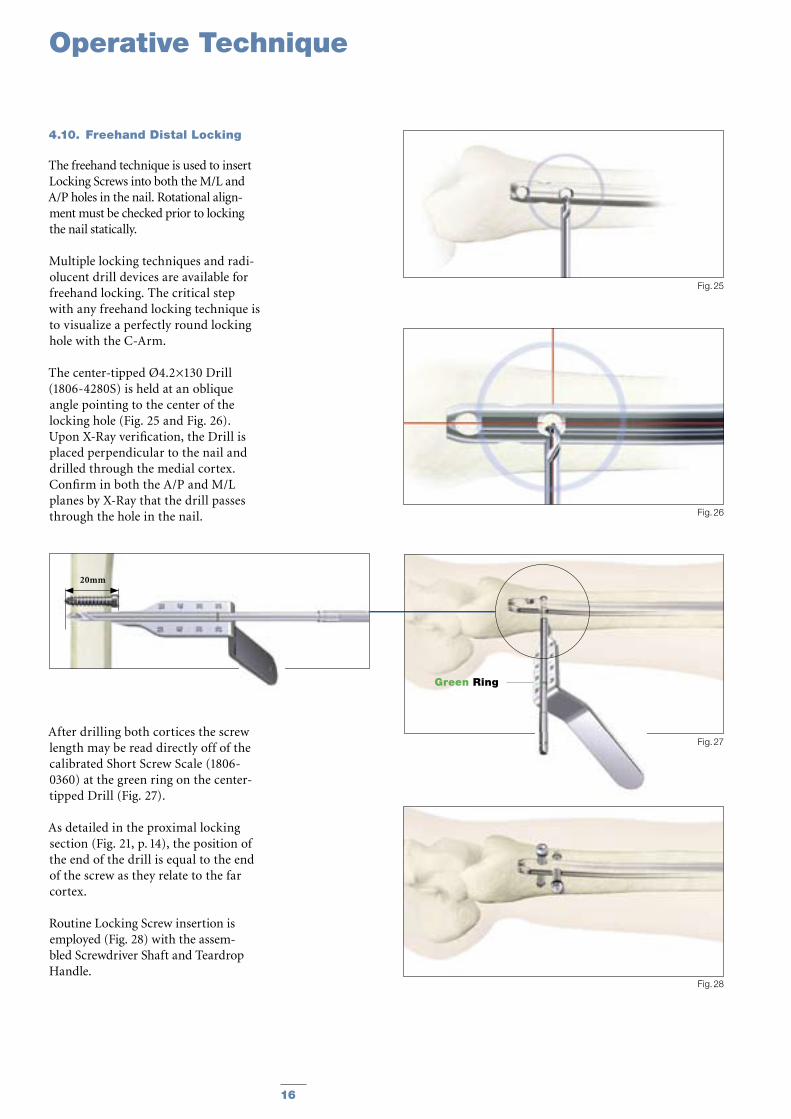
4.10. Freehand Distal Locking
The freehand technique is used to insert Locking Screws into both the M/L and A/P holes in the nail. Rotational align-ment must be checked prior to locking the nail statically.
Multiple locking techniques and radi-olucent drill devices are available for freehand locking. The critical step with any freehand locking technique is to visualize a perfectly round locking hole with the C-Arm.
The center-tipped Ø4.2×130 Drill (1806-4280S) is held at an oblique angle pointing to the center of the locking hole (Fig. 25 and Fig. 26). Upon X-Ray verification, the Drill is placed perpendicular to the nail and drilled through the medial cortex. Confirm in both the A/P and M/L planes by X-Ray that the drill passes through the hole in the nail.
After drilling both cortices the screw length may be read directly off of the calibrated Short Screw Scale (1806-0360) at the green ring on the center-tipped Drill (Fig. 27).
As detailed in the proximal locking section (Fig. 21, p. 14), the position of the end of the drill is equal to the end of the screw as they relate to the far cortex.
Routine Locking Screw insertion is employed (Fig. 28) with the assem-bled Screwdriver Shaft and Teardrop Handle.
Operative Technique
16 17
Fig. 30
Fig. 31
Standard +5mm +10mm +15mm +20mm +25mm +30mm +35mm
Fig. 29
Note: The Screwdriver Shaft may be used in conjunction with the
“optional” Short Screw Capture Sleeve (1806-0245).
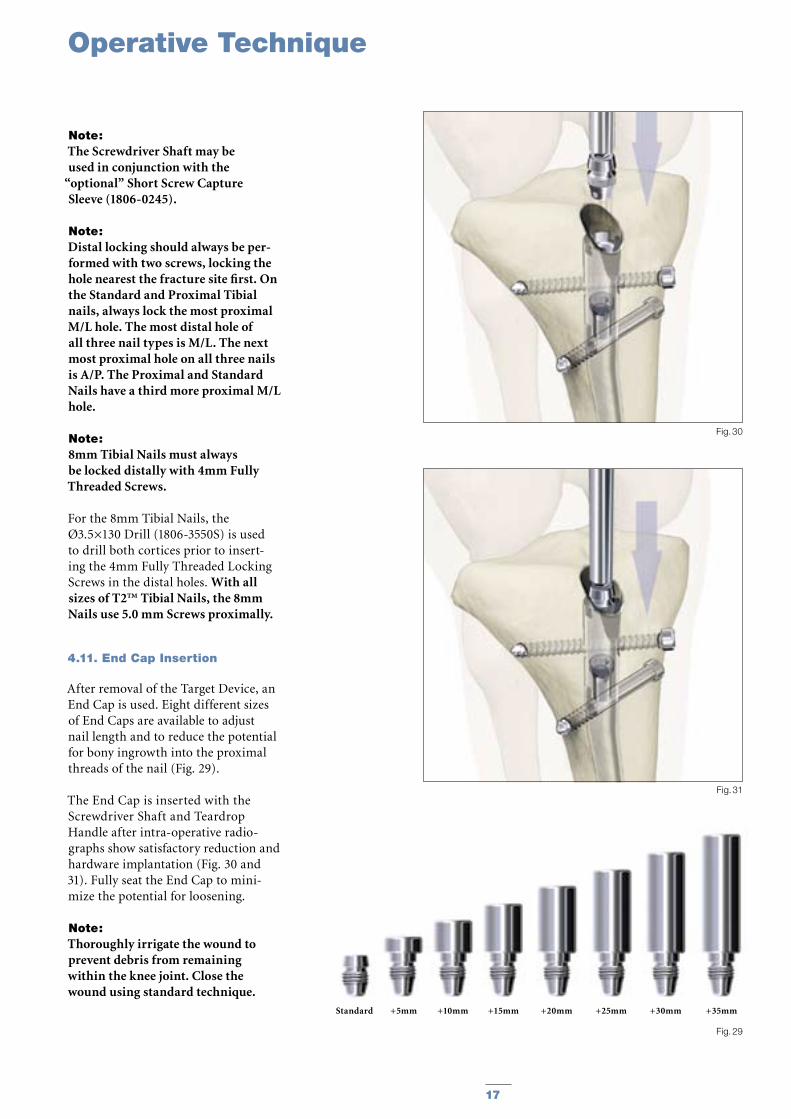
Note: Distal locking should always be per-formed with two screws, locking the hole nearest the fracture site first. On the Standard and Proximal Tibial nails, always lock the most proximal M/L hole. The most distal hole of all three nail types is M/L. The next most proximal hole on all three nails is A/P. The Proximal and Standard Nails have a third more proximal M/L hole.
Note: 8mm Tibial Nails must always be locked distally with 4mm Fully Threaded Screws.
For the 8mm Tibial Nails, the Ø3.5×130 Drill (1806-3550S) is used to drill both cortices prior to insert-ing the 4mm Fully Threaded Locking Screws in the distal holes. With all sizes of T2™ Tibial Nails, the 8mm Nails use 5.0 mm Screws proximally.
4.11. End Cap Insertion
After removal of the Target Device, an End Cap is used. Eight different sizes of End Caps are available to adjust nail length and to reduce the potential for bony ingrowth into the proximal threads of the nail (Fig. 29).
The End Cap is inserted with the Screwdriver Shaft and Teardrop Handle after intra-operative radio-graphs show satisfactory reduction and hardware implantation (Fig. 30 and 31). Fully seat the End Cap to mini-mize the potential for loosening.
Note: Thoroughly irrigate the wound to prevent debris from remaining within the knee joint. Close the wound using standard technique.
Operative Technique
18 19
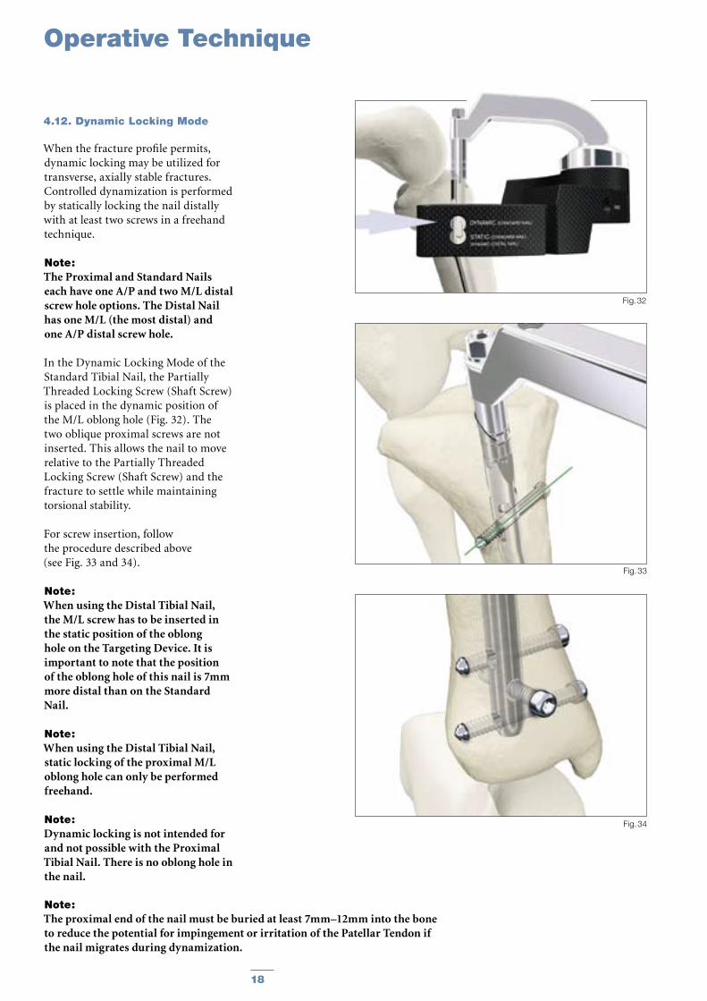
4.12. Dynamic Locking Mode
When the fracture profile permits, dynamic locking may be utilized for transverse, axially stable fractures. Controlled dynamization is performed by statically locking the nail distally with at least two screws in a freehand technique.
Note: The Proximal and Standard Nails each have one A/P and two M/L distal screw hole options. The Distal Nail has one M/L (the most distal) and one A/P distal screw hole.
In the Dynamic Locking Mode of the Standard Tibial Nail, the Partially Threaded Locking Screw (Shaft Screw) is placed in the dynamic position of the M/L oblong hole (Fig. 32). The two oblique proximal screws are not inserted. This allows the nail to move relative to the Partially Threaded Locking Screw (Shaft Screw) and the fracture to settle while maintaining torsional stability.
For screw insertion, follow the procedure described above (see Fig. 33 and 34).
Note: When using the Distal Tibial Nail, the M/L screw has to be inserted in the static position of the oblong hole on the Targeting Device. It is important to note that the position of the oblong hole of this nail is 7mm more distal than on the Standard Nail.
Note: When using the Distal Tibial Nail, static locking of the proximal M/L oblong hole can only be performed freehand.
Note: Dynamic locking is not intended for and not possible with the Proximal Tibial Nail. There is no oblong hole in the nail.
Fig. 34
Fig. 33
Fig. 32
Note: The proximal end of the nail must be buried at least 7mm–12mm into the bone to reduce the potential for impingement or irritation of the Patellar Tendon if the nail migrates during dynamization.
Operative Technique
18 19
4.13. Apposition/Compression Locking Mode
In transverse or axially stable frac-ture patterns, active apposition/compression increases fracture stabil-ity, may enhance fracture healing and allow for early weight bearing. The T2™ Standard Tibial Nail and T2™ Distal Tibial Nail provide the option to treat a tibial fracture with active mechanical apposition/compression prior to leaving the operating room.
Note: Distal freehand static locking with at least two screws must be per-formed prior to applying active, controlled apposition/compression to the fracture site.
If active apposition/compression is required for the T2 Standard Tibial Nail, a Partially Threaded Locking Screw is inserted via the Target Device in the dynamic position of the of the oblong hole. The Distal Tibial Nail uses the static position of the oblong hole.
This will allow for a maximum of 7mm of active, controlled apposition/compression. In order to insert the Partially Threaded Locking Screw (Shaft Screw), drill both cortices with the Ø4.2×260 Drill (1806-4250S). Correct screw length may be read from the calibration on the Drill at the end of the Drill Sleeve. The near cor-tex ONLY is overdrilled using the Ø5×180mm Drill (1806-5010S).
Note: It may be easier to insert the Compres-sion Screw prior to fully seating the nail. Once the nail tip has cleared the fracture site, the guide wire (if used) is withdrawn. With the proximal portion of the nail still not fully seated and extending out of the bone, the Nail Holding Screw is removed and the Compression Screw is inserted. Care should be taken that the shaft of the Compression Screw does not extend into the area of the oblong hole.
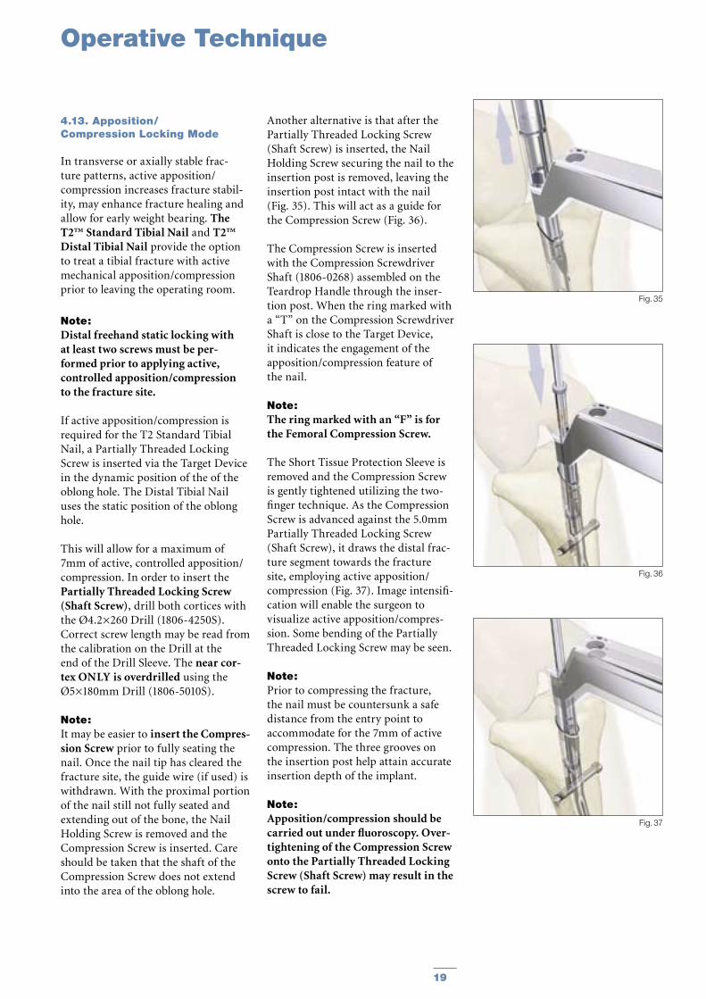
Another alternative is that after the Partially Threaded Locking Screw (Shaft Screw) is inserted, the Nail Holding Screw securing the nail to the insertion post is removed, leaving the insertion post intact with the nail (Fig. 35). This will act as a guide for the Compression Screw (Fig. 36).
The Compression Screw is inserted with the Compression Screwdriver Shaft (1806-0268) assembled on the Teardrop Handle through the inser-tion post. When the ring marked with a “T” on the Compression Screwdriver Shaft is close to the Target Device, it indicates the engagement of the apposition/compression feature of the nail.
Note: The ring marked with an “F” is for the Femoral Compression Screw.
The Short Tissue Protection Sleeve is removed and the Compression Screw is gently tightened utilizing the two-finger technique. As the Compression Screw is advanced against the 5.0mm Partially Threaded Locking Screw (Shaft Screw), it draws the distal frac-ture segment towards the fracture site, employing active apposition/compression (Fig. 37). Image intensifi-cation will enable the surgeon to visualize active apposition/compres-sion. Some bending of the Partially Threaded Locking Screw may be seen.
Note: Prior to compressing the fracture, the nail must be countersunk a safe distance from the entry point to accommodate for the 7mm of active compression. The three grooves on the insertion post help attain accurate insertion depth of the implant.
Note: Apposition/compression should be carried out under fluoroscopy. Over-tightening of the Compression Screw onto the Partially Threaded Locking Screw (Shaft Screw) may result in the screw to fail.
Fig. 37
Fig. 36
Fig. 35
Operative Technique

20 21
4.14. Advanced Locking Mode In order to achieve additional fixation, and to reduce the load on the Partially Threaded Locking Screw, the design of the T2™ Standard Tibial Nail and T2™ Distal Tibial Nail provide the opportunity to insert an additional Fully Threaded Locking Screw (Shaft Screw) into the more proximal of the two oblique holes after the optimum amount of apposition/compression is attained.
Affix the Compression Screw onto the self-retaining Compression Screw-driver Shaft. Remove the Nail Holding Screw leaving the Target Device in place. Advance the Compression Screw through the Target Device until the ring marked with a “ T ” on the Compres-sion Screwdriver Shaft is close to the Target Device and compression is applied (Fig. 38).
To insert the Advanced Compression Screw, follow the procedure under 4.13 on page 19.
Note: As previously described, it may be easier to insert the Compression Screw prior to fully seating the nail.
To reattach the Target Device, detach the Teardrop Handle from the Compression Screwdriver Shaft and screw the Nail Holding Screw over the Compression Screwdriver Shaft back into position (Fig. 39).
Prior to guided locking via the Target Device, the Nail Holding Screw must be securely tightened with the Insertion Wrench.
Note: When using the Advanced Compres-sion Screw, only the more proximal oblique hole can be locked with a screw. The more distal oblique hole will be partially blocked by the top of the Advanced Compression Screw regardless of the amount of compres-sion applied to the Shaft Screw in the M/L oblong hole.
Fig. 40
Fig. 38
Fig. 39
Operative Technique
20 21
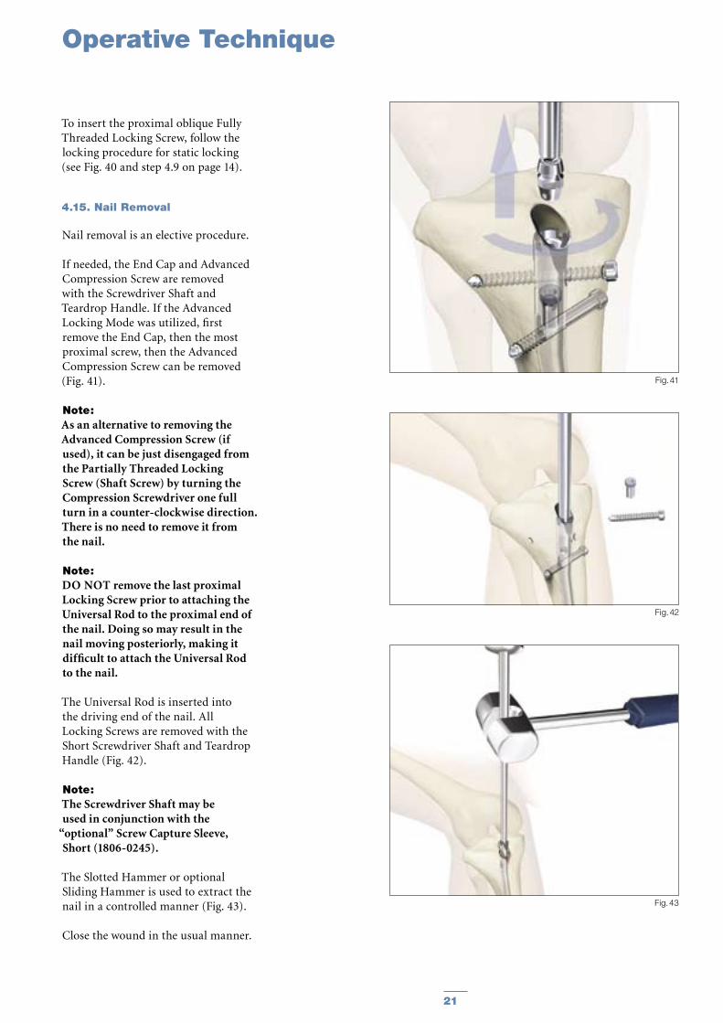
To insert the proximal oblique Fully Threaded Locking Screw, follow the locking procedure for static locking (see Fig. 40 and step 4.9 on page 14).
4.15. Nail Removal
Nail removal is an elective procedure.
If needed, the End Cap and Advanced Compression Screw are removed with the Screwdriver Shaft and Teardrop Handle. If the Advanced Locking Mode was utilized, first remove the End Cap, then the most proximal screw, then the Advanced Compression Screw can be removed (Fig. 41).
Note: As an alternative to removing the Advanced Compression Screw (if used), it can be just disengaged from the Partially Threaded Locking Screw (Shaft Screw) by turning the Compression Screwdriver one full turn in a counter-clockwise direction. There is no need to remove it from the nail.
Note: DO NOT remove the last proximal Locking Screw prior to attaching the Universal Rod to the proximal end of the nail. Doing so may result in the nail moving posteriorly, making it difficult to attach the Universal Rod to the nail.
The Universal Rod is inserted into the driving end of the nail. All Locking Screws are removed with the Short Screwdriver Shaft and Teardrop Handle (Fig. 42).
Note: The Screwdriver Shaft may be used in conjunction with the
“optional” Screw Capture Sleeve, Short (1806-0245).
The Slotted Hammer or optional Sliding Hammer is used to extract the nail in a controlled manner (Fig. 43).
Close the wound in the usual manner.
Fig. 41
Fig. 42
Fig. 43
Operative Technique

22 23
Fig. 44
Fig. 45
Mechanics of Blocking Screw
Radiographic location ofSuperolateral Nail Entry Portal
Superolateral Entry Portal
Fig. 46
Blocking Screw
Awl
Nail
Blocking Screw
Blocking Screw Technique (optional)
Fig. 47
Just medial to lateral spine Anterior adjacent to joint

22 23
Superolateral Entry Portal
The nail often sits against the pos-terior cortex which causes anterior angulation of the fracture because the shaft position is fixed by the nail (Fig. 48).
For Varus/ Valgus AdjustmentOne of the advantages of the very proximal bend in the nail, is its’ use-fulness in correcting varus/valgus angulation. Do not lock the nail dis-tally until after angular correction.
The principle of the use of a Blocking Screw is to prevent posterior nail passage by decreasing the effective diameter of the canal and directing the nail more anterior as shown
(Fig. 49). Using the superolateral entry point and with the Blocking Screw in place, the nail accurately aligns the shaft (fracture) (Fig. 50) (6, 7, 8)
Fig. 49
Blocking Screw
Placed to PreventNail passage
Fig. 50
Fig. 51a Fig. 51b Fig. 51c
Blocking Screw
Cross Locking Screws
Blocking Screw
10° Herzog Bend
Place the Blocking Screw at the level of the Proximal (Herzog) Bend (Fig. 51a). In cases where a Blocking Screw is used, simple rotation of the nail (Fig. 51b) will allow the Herzog Bend to correct the angulation (Fig. 51c).
Note: As an option, or in an exchange/revision nailing with a more distal entry portal, this principal can also be applied with a Lateral Blocking Screw placed A/P as an alternative method to help prevent Varus/Valgus deformity.
Fig. 48
Blocking Screw Technique (optional)

24 25
REF Diameter Length mm mm
1822-0924S 9.0 240 1822-0925S 9.0 255 1822-0927S 9.0 270 1822-0928S 9.0 285 1822-0930S 9.0 300 1822-0931S 9.0 315 1822-0933S 9.0 330 1822-0934S 9.0 345 1822-0936S 9.0 360 1822-0937S 9.0 375 1822-0939S 9.0 390 1822-0940S 9.0 405 1822-0942S 9.0 420
1822-1024S 10.0 240 1822-1025S 10.0 255 1822-1027S 10.0 270 1822-1028S 10.0 285 1822-1030S 10.0 300 1822-1031S 10.0 315 1822-1033S 10.0 330 1822-1034S 10.0 345 1822-1036S 10.0 360 1822-1037S 10.0 375 1822-1039S 10.0 390 1822-1040S 10.0 405 1822-1042S 10.0 420
1822-1124S 11.0 240 1822-1125S 11.0 255 1822-1127S 11.0 270 1822-1128S 11.0 285 1822-1130S 11.0 300 1822-1131S 11.0 315 1822-1133S 11.0 330 1822-1134S 11.0 345 1822-1136S 11.0 360 1822-1137S 11.0 375 1822-1139S 11.0 390 1822-1140S 11.0 405 1822-1142S 11.0 420
1822-1224S 12.0 240 1822-1225S 12.0 255 1822-1227S 12.0 270 1822-1228S 12.0 285 1822-1230S 12.0 300 1822-1231S 12.0 315 1822-1233S 12.0 330 1822-1234S 12.0 345 1822-1236S 12.0 360 1822-1237S 12.0 375 1822-1239S 12.0 390 1822-1240S 12.0 405 1822-1242S 12.0 420
1822-1324S 13.0 240 1822-1325S 13.0 255 1822-1327S 13.0 270 1822-1328S 13.0 285 1822-1330S 13.0 300 1822-1331S 13.0 315 1822-1333S 13.0 330 1822-1334S 13.0 345 1822-1336S 13.0 360 1822-1337S 13.0 375 1822-1339S 13.0 390 1822-1340S 13.0 405 1822-1342S 13.0 420
T2 Standard Tibial Nail
REF Diameter Length mm mm
1822-1424S 14.0 240 1822-1425S 14.0 255 1822-1427S 14.0 270 1822-1428S 14.0 285 1822-1430S 14.0 300 1822-1431S 14.0 315 1822-1433S 14.0 330 1822-1434S 14.0 345 1822-1436S 14.0 360 1822-1437S 14.0 375 1822-1439S 14.0 390 1822-1440S 14.0 405 1822-1442S 14.0 420
1822-1524S 15.0 240 1822-1525S 15.0 255 1822-1527S 15.0 270 1822-1528S 15.0 285 1822-1530S 15.0 300 1822-1531S 15.0 315 1822-1533S 15.0 330 1822-1534S 15.0 345 1822-1536S 15.0 360 1822-1537S 15.0 375 1822-1539S 15.0 390 1822-1540S 15.0 405 1822-1542S 15.0 420
Implants in sterile packaging
Note: Check with local representative regarding availability of nail sizes and types.
Ordering Information - Implants

24 25
REF Diameter Length mm mm
1823-0924S 9.0 240 1823-0925S 9.0 255 1823-0927S 9.0 270 1823-0928S 9.0 285 1823-0930S 9.0 300 1823-0931S 9.0 315 1823-0933S 9.0 330 1823-0934S 9.0 345 1823-0936S 9.0 360 1823-0937S 9.0 375 1823-0939S 9.0 390 1823-0940S 9.0 405 1823-0942S 9.0 420
1823-1024S 10.0 240 1823-1025S 10.0 255 1823-1027S 10.0 270 1823-1028S 10.0 285 1823-1030S 10.0 300 1823-1031S 10.0 315 1823-1033S 10.0 330 1823-1034S 10.0 345 1823-1036S 10.0 360 1823-1037S 10.0 375 1823-1039S 10.0 390 1823-1040S 10.0 405 1823-1042S 10.0 420
1823-1124S 11.0 240 1823-1125S 11.0 255 1823-1127S 11.0 270 1823-1128S 11.0 285 1823-1130S 11.0 300 1823-1131S 11.0 315 1823-1133S 11.0 330 1823-1134S 11.0 345 1823-1136S 11.0 360 1823-1137S 11.0 375 1823-1139S 11.0 390 1823-1140S 11.0 405 1823-1142S 11.0 420
1823-1224S 12.0 240 1823-1225S 12.0 255 1823-1227S 12.0 270 1823-1228S 12.0 285 1823-1230S 12.0 300 1823-1231S 12.0 315 1823-1233S 12.0 330 1823-1234S 12.0 345 1823-1236S 12.0 360 1823-1237S 12.0 375 1823-1239S 12.0 390 1823-1240S 12.0 405 1823-1242S 12.0 420
1823-1324S 13.0 2401823-1325S 13.0 255 1823-1327S 13.0 270 1823-1328S 13.0 285 1823-1330S 13.0 300 1823-1331S 13.0 315 1823-1333S 13.0 330 1823-1334S 13.0 345 1823-1336S 13.0 360 1823-1337S 13.0 375 1823-1339S 13.0 390 1823-1340S 13.0 405 1823-1342S 13.0 420
T2™ Proximal Tibial Nail
REF Diameter Length mm mm
1823-1424S 14.0 240 1823-1425S 14.0 255 1823-1427S 14.0 270 1823-1428S 14.0 285 1823-1430S 14.0 300 1823-1431S 14.0 315 1823-1433S 14.0 330 1823-1434S 14.0 345 1823-1436S 14.0 360 1823-1437S 14.0 375 1823-1439S 14.0 390 1823-1440S 14.0 405 1823-1442S 14.0 420
1823-1524S 15.0 240 1823-1525S 15.0 255 1823-1527S 15.0 270 1823-1528S 15.0 285 1823-1530S 15.0 300 1823-1531S 15.0 315 1823-1533S 15.0 330 1823-1534S 15.0 345 1823-1536S 15.0 360 1823-1537S 15.0 375 1823-1539S 15.0 390 1823-1540S 15.0 405 1823-1542S 15.0 420
Ordering Information - Implants
Implants in sterile packaging
Proximal Tibial Nails available as Special Order.
Note: Check with local representative regarding availability of nail sizes and types.

26 27
1896-5025S1896-5027S1896-5030S1896-5032S1896-5035S1896-5037S1896-5040S1896-5042S1896-5045S1896-5047S1896-5050S1896-5052S1896-5055S1896-5057S1896-5060S1896-5065S1896-5070S1896-5075S1896-5080S1896-5085S1896-5090S1896-5095S1896-5100S1896-5105S1896-5110S1896-5115S1896-5120S
5.0 25.05.0 27.55.0 30.05.0 32.55.0 35.0 5.0 37.55.0 40.0 5.0 42.55.0 45.0 5.0 47.5 5.0 50.05.0 52.5 5.0 55.0 5.0 57.5 5.0 60.0 5.0 65.0 5.0 70.0 5.0 75.0 5.0 80.0 5.0 85.0 5.0 90.0 5.0 95.0 5.0 100.05.0 105.05.0 110.05.0 115.05.0 120.0
REF Diameter Length mm mm
1824-1024S 10.0 2401824-1025S 10.0 2551824-1027S 10.0 2701824-1028S 10.0 2851824-1030S 10.0 3001824-1031S 10.0 3151824-1033S 10.0 3301824-1034S 10.0 3451824-1036S 10.0 3601824-1037S 10.0 3751824-1039S 10.0 3901824-1040S 10.0 4051824-1042S 10.0 420
T2 Distal Tibial Nail 5mm Fully Threaded Locking Screws+
Ordering Information - Implants
REF Diameter Length mm mm
Distal Tibial Nails available as Special Order
+ Outside of the U. S., Locking Screws may be ordered non-sterile without the “S” at the end of the corresponding Catalogue Number.
Shaft Screws
REF Diameter Length mm mm
1896-4020S 4.0 201896-4025S 4.0 251896-4030S 4.0 301896-4035S 4.0 351896-4040S 4.0 401896-4045S 4.0 451896-4050S 4.0 501896-4055S 4.0 551896-4060S 4.0 60
4mm Fully Threaded Locking Screws
1891-5025S1891-5030S1891-5035S1891-5040S1891-5045S1891-5050S1891-5055S1891-5060S1891-5065S1891-5070S1891-5075S1891-5080S1891-5085S1891-5090S1891-5095S1891-5100S1891-5105S1891-5110S1891-5115S1891-5120S
5mm Partially Threaded Locking Screws+
5.0 255.0 305.0 355.0 405.0 455.0 505.0 555.0 605.0 655.0 705.0 755.0 805.0 855.0 905.0 955.0 1005.0 1055.0 1105.0 1155.0 120
REF Diameter Length mm mm

26 27
REF Diameter Length mm mm
1822-0824S 8.0 2401822-0825S 8.0 2551822-0827S 8.0 2701822-0828S 8.0 2851822-0830S 8.0 3001822-0831S 8.0 3151822-0833S 8.0 3301822-0834S 8.0 3451822-0836S 8.0 3601822-0837S 8.0 3751822-0839S 8.0 3901822-0840S 8.0 4051822-0842S 8.0 420
8mm Tibial Nail, Standard
REF Diameter Length mm mm
1823-0824S 8.0 2401823-0825S 8.0 2551823-0827S 8.0 2701823-0828S 8.0 2851823-0830S 8.0 3001823-0831S 8.0 3151823-0833S 8.0 3301823-0834S 8.0 3451823-0836S 8.0 3601823-0837S 8.0 3751823-0839S 8.0 3901823-0840S 8.0 4051823-0842S 8.0 420
8mm Tibial Nail, Proximal
Implants in sterile packaging
Note: Check with local representative regarding availability of nail sizes and types.
Partially Threaded Locking Screws (Shaft Screws) are used in conjunction with the Advanced Compression Screw feature of the Distal and Standard Nails, or may also be used as a “Blocking Screw“ with all three nail types, including the Proximal Nail.
(See optional “Blocking Screw Technique“ section on pages 22 and 23)
Ordering Information - Implants
REF Diameter Length mm mm
1822-0001S 8.0
+5mm +10mm
+15mm
StandardFully Threaded
REF Diameter Length mm mm
1822-0004S 7.0 Fully Threaded1822-0003S 8.0 Standard1822-0005S 11.5 + 5mm1822-0010S 11.5 +10mm1822-0015S 11.5 +15mm1822-0020S 11.5 +20mm1822-0025S 11.5 +25mm1822-0030S 11.5 +30mm1822-0035S 11.5 +35mm
End Caps
+20mm
+25mm +30mm
+35mm
Advanced Compression Screws, Tibia
28 29
Ordering Information - Instruments
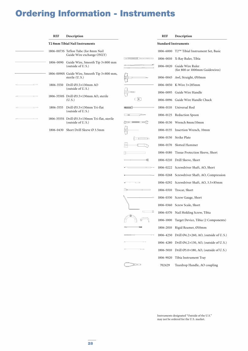
REF Description
T2 8mm Tibial Nail Instruments
1806-0073S Teflon Tube (for 8mm Nail Guide Wire exchange ONLY)
1806-0090 Guide Wire, Smooth Tip 3×800 mm (outside of U. S.)
1806-0090S Guide Wire, Smooth Tip 3×800 mm, sterile (U. S.)
1806-3550 Drill Ø3.5×130mm AO (outside of U. S.)
1806-3550S Drill Ø3.5×130mm AO, sterile (U. S.)
1806-3555 Drill Ø3.5×130mm Tri-f lat (outside of U. S.)
1806-3555S Drill Ø3.5×130mm Tri-f lat, sterile (outside of U. S.)
1806-0430 Short Drill Sleeve Ø 3.5mm
Instruments designated “Outside of the U.S.” may not be ordered for the U.S. market.
REF Description
Standard Instruments
1806-6000 T2™ Tibial Instrument Set, Basic
1806-0010 X-Ray Ruler, Tibia
1806-0020 Guide Wire Ruler (for 800 or 1000mm Guidewires)
1806-0045 Awl, Straight, Ø10mm
1806-0050 K-Wire 3×285mm
1806-0095 Guide Wire Handle
1806-0096 Guide Wire Handle Chuck
1806-0110 Universal Rod
1806-0125 Reduction Spoon
1806-0130 Wrench 8mm/10mm
1806-0135 Insertion Wrench, 10mm
1806-0150 Strike Plate
1806-0170 Slotted Hammer
1806-0180 Tissue Protection Sleeve, Short
1806-0210 Drill Sleeve, Short
1806-0222 Screwdriver Shaft, AO, Short
1806-0268 Screwdriver Shaft, AO, Compression
1806-0292 Screwdriver Shaft, AO, 3.5×85mm
1806-0310 Trocar, Short
1806-0330 Screw Gauge, Short
1806-0360 Screw Scale, Short
1806-0370 Nail Holding Screw, Tibia
1806-1000 Target Device, Tibia (2 Components)
1806-2010 Rigid Reamer, Ø10mm
1806-4250 Drill Ø4.2×260, AO, (outside of U. S.)
1806-4280 Drill Ø4.2×130, AO, (outside of U. S.)
1806-5010 Drill Ø5.0×180, AO, (outside of U. S.)
1806-9020 Tibia Instrument Tray
702429 Teardrop Handle, AO coupling
28 29
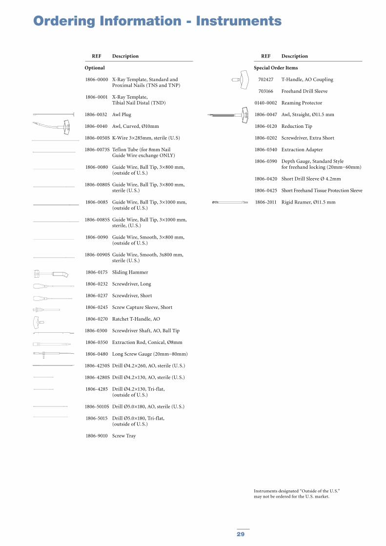
REF Description
Optional
1806-0000 X-Ray Template, Standard and Proximal Nails (TNS and TNP)
1806-0001 X-Ray Template, Tibial Nail Distal (TND)
1806-0032 Awl Plug
1806-0040 Awl, Curved, Ø10mm
1806-0050S K-Wire 3×285mm, sterile (U. S)
1806-0073S Teflon Tube (for 8mm Nail Guide Wire exchange ONLY)
1806-0080 Guide Wire, Ball Tip, 3×800 mm, (outside of U. S.)
1806-0080S Guide Wire, Ball Tip, 3×800 mm, sterile (U. S.)
1806-0085 Guide Wire, Ball Tip, 3×1000 mm, (outside of U. S.)
1806-0085S Guide Wire, Ball Tip, 3×1000 mm, sterile, (U. S.)
1806-0090 Guide Wire, Smooth, 3×800 mm, (outside of U. S.)
1806-0090S Guide Wire, Smooth, 3x800 mm, sterile (U. S.)
1806-0175 Sliding Hammer
1806-0232 Screwdriver, Long
1806-0237 Screwdriver, Short
1806-0245 Screw Capture Sleeve, Short
1806-0270 Ratchet T-Handle, AO
1806-0300 Screwdriver Shaft, AO, Ball Tip
1806-0350 Extraction Rod, Conical, Ø8mm
1806-0480 Long Screw Gauge (20mm−80mm)
1806-4250S Drill Ø4.2×260, AO, sterile (U. S.)
1806-4280S Drill Ø4.2×130, AO, sterile (U. S.)
1806-4285 Drill Ø4.2×130, Tri-f lat, (outside of U. S.)
1806-5010S Drill Ø5.0×180, AO, sterile (U. S.)
1806-5015 Drill Ø5.0×180, Tri-f lat, (outside of U. S.)
1806-9010 Screw Tray
REF Description
Special Order Items
702427 T-Handle, AO Coupling
703166 Freehand Drill Sleeve
0140-0002 Reaming Protector
1806-0047 Awl, Straight, Ø11.5 mm
1806-0120 Reduction Tip
1806-0202 Screwdriver, Extra Short
1806-0340 Extraction Adapter
1806-0390 Depth Gauge, Standard Style for freehand locking (20mm−60mm)
1806-0420 Short Drill Sleeve Ø 4.2mm
1806-0425 Short Freehand Tissue Protection Sleeve
1806-2011 Rigid Reamer, Ø11.5 mm
Instruments designated “Outside of the U. S.”may not be ordered for the U. S. market.
Ordering Information - Instruments
30 31
Ordering Information - Instruments
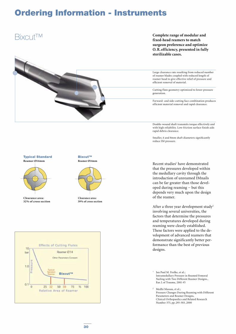
Complete range of modular and fixed-head reamers to match surgeon preference and optimize O. R. efficiency, presented in fully sterilizable cases.
Recent studies1 have demonstrated that the pressures developed within the medullary cavity through the introduction of unreamed IMnails can be far greater than those devel-oped during reaming − but this depends very much upon the design of the reamer.
After a three year development study2 involving several universities, the factors that determine the pressures and temperatures developed during reaming were clearly established. These factors were applied to the de-velopment of advanced reamers that demonstrate significantly better per-formance than the best of previous designs.
1 Jan Paul M. Frolke, et al. ; Intramedullary Pressure in Reamed Femoral
Nailing with Two Different Reamer Designs., Eur. J. of Trauma, 2001 #5
2 Medhi Massau, et al.; Pressure Changes During Reaming with Different
Parameters and Reamer Designs, Clinical Orthopaedics and Related Research
Number 373, pp. 295-303, 2000
Large clearance rate resulting from reduced number of reamer blades coupled with reduced length of reamer head to give effective relief of pressure and efficient removal of material.
Cutting f lute geometry optimized to lower pressure generation.
Forward- and side-cutting face combination produces efficient material removal and rapid clearance.
Double-wound shaft transmits torque effectively and with high reliability. Low-friction surface finish aids rapid debris clearance.
Smaller, 6 and 8mm shaft diameters significantly reduce IM pressure.
Bixcut™
Typical StandardReamer Ø14mm
Clearance area :32% of cross section
Bixcut™Reamer Ø14mm
Clearance area :59% of cross section
Bixcut™
30 31
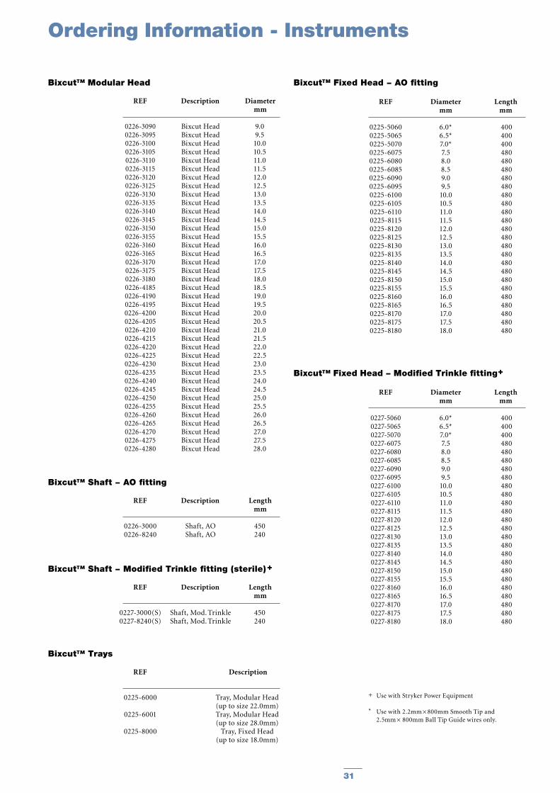
REF Description Diameter mm
Bixcut™ Modular Head
REF Diameter Length mm mm
Bixcut™ Fixed Head − AO fitting
REF Description Length mm
Bixcut™ Shaft − AO fitting
REF Description Length mm
Bixcut™ Shaft − Modified Trinkle fitting (sterile) +
REF Description
Bixcut™ Trays
REF Diameter Length mm mm
Bixcut™ Fixed Head − Modified Trinkle fitting+
Ordering Information - Instruments
0226-30900226-30950226-31000226-31050226-31100226-31150226-31200226-31250226-31300226-31350226-31400226-31450226-31500226-31550226-31600226-31650226-31700226-31750226-31800226-41850226-41900226-41950226-42000226-42050226-42100226-42150226-42200226-42250226-42300226-42350226-42400226-42450226-42500226-42550226-42600226-42650226-42700226-42750226-4280
Bixcut HeadBixcut HeadBixcut HeadBixcut HeadBixcut HeadBixcut HeadBixcut HeadBixcut HeadBixcut HeadBixcut HeadBixcut HeadBixcut HeadBixcut HeadBixcut HeadBixcut HeadBixcut HeadBixcut HeadBixcut HeadBixcut HeadBixcut HeadBixcut HeadBixcut HeadBixcut HeadBixcut HeadBixcut HeadBixcut HeadBixcut HeadBixcut HeadBixcut HeadBixcut HeadBixcut HeadBixcut HeadBixcut HeadBixcut HeadBixcut HeadBixcut HeadBixcut HeadBixcut HeadBixcut Head
9.09.5
10.010.511.011.512.012.513.013.514.014.515.015.516.016.517.017.518.018.519.019.520.020.521.021.522.022.523.023.524.024.525.025.526.026.527.027.528.0
0226-30000226-8240
Shaft, AOShaft, AO
450240
0227-3000(S)0227-8240(S)
Shaft, Mod. TrinkleShaft, Mod. Trinkle
450240
0225-6000
0225-6001
0225-8000
Tray, Modular Head (up to size 22.0mm)Tray, Modular Head (up to size 28.0mm)
Tray, Fixed Head (up to size 18.0mm)
0227-50600227-50650227-50700227-60750227-60800227-60850227-60900227-60950227-61000227-61050227-61100227-81150227-81200227-81250227-81300227-81350227-81400227-81450227-81500227-81550227-81600227-81650227-81700227-81750227-8180
6.0*6.5*7.0*7.58.08.59.09.5
10.010.511.011.512.012.513.013.514.014.515.015.516.016.517.017.518.0
400400400480480480480480480480480480480480480480480480480480480480480480480
0225-50600225-50650225-50700225-60750225-60800225-60850225-60900225-60950225-61000225-61050225-61100225-81150225-81200225-81250225-81300225-81350225-81400225-81450225-81500225-81550225-81600225-81650225-81700225-81750225-8180
6.0*6.5*7.0*7.58.08.59.09.5
10.010.511.011.512.012.513.013.514.014.515.015.516.016.517.017.518.0
400400400480480480480480480480480480480480480480480480480480480480480480480
+ Use with Stryker Power Equipment
* Use with 2.2mm × 800mm Smooth Tip and 2.5mm × 800mm Ball Tip Guide wires only.

Joint Replacements
Trauma
Spine
Micro Implants
Orthobiologics
Instruments
Interventional Pain
Navigation
Endoscopy
Communications
Patient Handling Equipment
EMS Equipment
Stryker Trauma GmbHProf.-Küntscher-Strasse 1-5D-24232 SchönkirchenGermany
www.trauma.stryker.com
The information presented in this brochure is intended to demonstrate a Stryker product. Always refer to the package insert, product label and/or user instructions before using any Stryker product. Products may not be available in all markets. Product availability is subject to the regulatory or medical practices that govern individual markets. Please contact your Stryker representative if you have questions about the availability of Stryker products in your area.
Products referenced with ™ designation are trademarks of Stryker. Products referenced with ® designation are registered trademarks of Stryker.
Literature Number : B1000005LOT B2104
Copyright © 2004 StrykerPrinted in Germany