table 2-19. northwest rail alignment fencing recommendations · 2010-02-25 · the following is a...
TRANSCRIPT

Northwest Rail Corridor Draft Environmental Evaluation
Northwest Rai l Corr idor
2-61 February 2010
TABLE 2-19. NORTHWEST RAIL ALIGNMENT FENCING RECOMMENDATIONS Section and Segment Fence Type
Broomfield Section
US 36 – West 120th Avenue
• High-Tensile Wire Type II (or High-Tensile Wire Type IV if additional development occurs before implementation of NWR)
• High-Tensile Wire Type I in vicinity of Airport Creek
West 120th Avenue– Nickel Street
• High-Tensile Wire Type II on southwest side of rail alignment
• High-Tensile Wire Type IV on northeast side of rail alignment and in vicinity of housing
Nickel Street – Brainard Drive
• High-Tensile Wire Type II on southwest side of rail alignment and northeast side of rail alignment between Nickel Street and Hunter Douglas property
• High-Tensile Wire Type I between Hunter Douglas property and Brainard Drive
Brainard Drive – Northwest Parkway • High-Tensile Wire Type I (or High-Tensile Wire Type II or
IV on west side of rail alignment if additional development occurs before implementation of the NWR Corridor)
Louisville Section Northwest Parkway – Dillon Road • High-Tensile Wire Type I
Dillon Road – Lock Street (Louisville City Park)
• High-Tensile Wire Type I on west side of rail alignment • High-Tensile Wire Type I (modified with denser strand
design) on east side of rail alignment
Lock Street – South Boulder Road • High-Tensile Wire Type IV (modified to permit wildlife crossing)
South Boulder Road – Baseline Road • High-Tensile Wire Type IV (modified to permit wildlife crossing)
Boulder Section Baseline Road – Arapahoe Road • High-Tensile Wire Type I
Arapahoe Road – Boulder Creek • High-Tensile Wire Type II • High-Tensile Wire Type I in vicinity of Boulder Creek, South
Boulder Creek, and Dry Creek No. 2 Ditch
Boulder Creek – Foothills Parkway • High-Tensile Wire Type II • High-Tensile Wire Type I in vicinity of Goose Creek and
Wonderland Creek Foothills Parkway – 55th Street • High-Tensile Wire Type I 55th Street – 63rd Street • High-Tensile Wire Type I 63rd Street – SH 52 • High-Tensile Wire Type I Longmont Section SH 52 – Niwot Road • High-Tensile Wire Type I Niwot Road – Hover Road • High-Tensile Wire Type I Hover Road – Sunset • High-Tensile Wire Type II Sunset – Nelson • High-Tensile Wire Type I Nelson – Downtown Longmont • High-Tensile Wire Type II Source: NWR Corridor Project Team, 2009. Notes: 1 Proposed fence type for the shared alignment between DUS and Pecos is chain link. I-76 = Interstate 76 NWR = Northwest Rail SH = State Highway

Northwest Rail Corridor Draft Environmental Evaluation
Northwest Rai l Corr idor
February 2010 2-62
FIGURE 2-16. GEOGRAPHIC LIMITS OF FENCING TYPES
Source: NWR Corridor Project Team, 2008; DRCOG 2007-08; CDOT 2006; ESRI SDC, 2004.

Northwest Rail Corridor Draft Environmental Evaluation
Northwest Rai l Corr idor
2-63 February 2010
2.3.4 Conclusion As a result of the Level 1 – Conceptual Alternative Screening and Level 2 – Preferred Alternative Refinement, Alternative B – Double Track from Denver to Longmont was selected as the Preferred Alternative. Alternative A – No Action and the Preferred Alternative, with DMU vehicle technology, were carried forward to undergo detailed evaluation in the NWR Corridor EE. Figure 2-17 depicts a summary of the screening process.
FIGURE 2-17. ALTERNATIVES SCREENING PROCESS
Source: NWR Corridor Project Team, 2008.

Northwest Rail Corridor Draft Environmental Evaluation
Northwest Rai l Corr idor
February 2010 2-64
2.4 DESCRIPTION OF NO ACTION AND PREFERRED ALTERNATIVES
The following is a brief description of the No Action Alternative and the Preferred Alternative.
2.4.1 No Action Alternative The No Action Alternative represents the Denver metropolitan region and the project study area in a 2035 horizon-year scenario. The No Action Alternative includes the existing and committed transportation improvements in DRCOG’s fiscally constrained 2035 Metro Vision Regional Transportation Plan (2035 MVRTP) (DRCOG 2007a). It also includes the entire FasTracks Plan, except for the NWR Corridor Project. Under the No Action Alternative, no new rail transit projects would be constructed within the project study area for the NWR Corridor. The No Action Alternative provides a basis for comparison to the build alternatives.
2.4.2 Preferred Alternative Elements of the Preferred Alternative include the rail alignment, station locations, and operational characteristics as described below and depicted in Figure 2-18.
2.4.2.1 Alignment The NWR Corridor Project will be phased; the first phase, from DUS to the South Westminster/71st Avenue Station (approximately up to Bradburn Boulevard) would use EMU technology. Phase 2 would use DMU technology from DUS to Longmont and would share the tracks used by the EMU vehicles in the Phase 1 segment between DUS and the South Westminster/71st Avenue Station. Ultimately, the Preferred Alternative would begin at DUS in downtown Denver and extend northwest along the BNSF Railway Company alignment to Boulder and then northeast to Downtown Longmont. The NWR Corridor is approximately 41 miles in length. The first 3.5 miles of the alignment between DUS and Pecos Street would be shared with the Gold Line Project. The remaining 37.5 miles of track would be dedicated to the NWR Corridor Project, but shared with existing freight operations.
Between the South Westminster/71st Avenue Station and Longmont, the existing BNSF Railway Company track would be rehabilitated/replaced, and one new track, adjacent to the existing BNSF Railway Company track, would be constructed. Both tracks would be utilized by freight and commuter rail vehicles. For Phase 1, RTD would operate on tracks exclusively dedicated to commuter rail transit from DUS to the South Westminster/71st Avenue Station. Future phases constructed beyond the South Westminster/71st Avenue Station would share track and ROW with freight operations and would require an operating easement from the BNSF Railway Company. RTD is currently negotiating the necessary agreements with the BNSF Railway Company.

Northwest Rail Corridor Draft Environmental Evaluation
Northwest Rai l Corr idor
2-65 February 2010
2.4.2.2 Stations There are 11 stations proposed as part of the Preferred Alternative, located at:
• South Westminster/71st Avenue • East Boulder • Westminster/88th Avenue • Boulder Transit Village • Walnut Creek • Gunbarrel • Broomfield/116th Avenue • Twin Peaks • Flatiron • Downtown Longmont • Downtown Louisville
Four of the 11 stations (Westminster/88th Avenue, Broomfield/116th Avenue, East Boulder, and Twin Peaks) would not be funded by FasTracks and would require additional funding sources in order to be constructed. The environmental impacts (including aquatic) related to the four unfunded stations are included as part of the evaluation in this EE.

Northwest Rail Corridor Draft Environmental Evaluation
Northwest Rai l Corr idor
February 2010 2-66
FIGURE 2-18. PREFERRED ALTERNATIVE
Source: NWR Corridor Project Team, 2009.

Northwest Rail Corridor Draft Environmental Evaluation
Northwest Rai l Corr idor
2-67 February 2010
Per RTD, Board of Directors policy established in 1994 and reconfirmed in 2003, new rapid transit stations are typically named for the nearest street intersections, major cross street, or the name of the geographic location of the area. The policy recognizes the need for flexibility in station naming and the Board’s prerogative to select alternate names. Station names in this EE document that are not in conformance with this policy will be considered preliminary until final naming is approved by the Board.
Concept plans for the 11 stations are shown in Figures 2-19 through 2-30.
FIGURE 2-19. SOUTH WESTMINSTER/71ST AVENUE STATION CONCEPT PLAN
Source: NWR Corridor Project Team, 2009.

Northwest Rail Corridor Draft Environmental Evaluation
Northwest Rai l Corr idor
February 2010 2-68
FIGURE 2-20. WESTMINSTER/88TH AVENUE STATION CONCEPT PLAN
Source: NWR Corridor Project Team, 2009.

Northwest Rail Corridor Draft Environmental Evaluation
Northwest Rai l Corr idor
2-69 February 2010
FIGURE 2-21. WALNUT CREEK STATION CONCEPT PLAN
Source: NWR Corridor Project Team, 2009.

Northwest Rail Corridor Draft Environmental Evaluation
Northwest Rai l Corr idor
February 2010 2-70
FIGURE 2-22. BROOMFIELD/116TH AVENUE STATION CONCEPT PLAN
Source: NWR Corridor Project Team, 2009.

Northwest Rail Corridor Draft Environmental Evaluation
Northwest Rai l Corr idor
2-71 February 2010
FIGURE 2-23. FLATIRON STATION CONCEPT PLAN
Source: NWR Corridor Project Team, 2009.

Northwest Rail Corridor Draft Environmental Evaluation
Northwest Rai l Corr idor
February 2010 2-72
FIGURE 2-24. DOWNTOWN LOUISVILLE STATION CONCEPT PLAN
Source: NWR Corridor Project Team, 2009.
Northwest Rail Corridor Draft Environmental Evaluation
Northwest Rai l Corr idor
2-73 February 2010
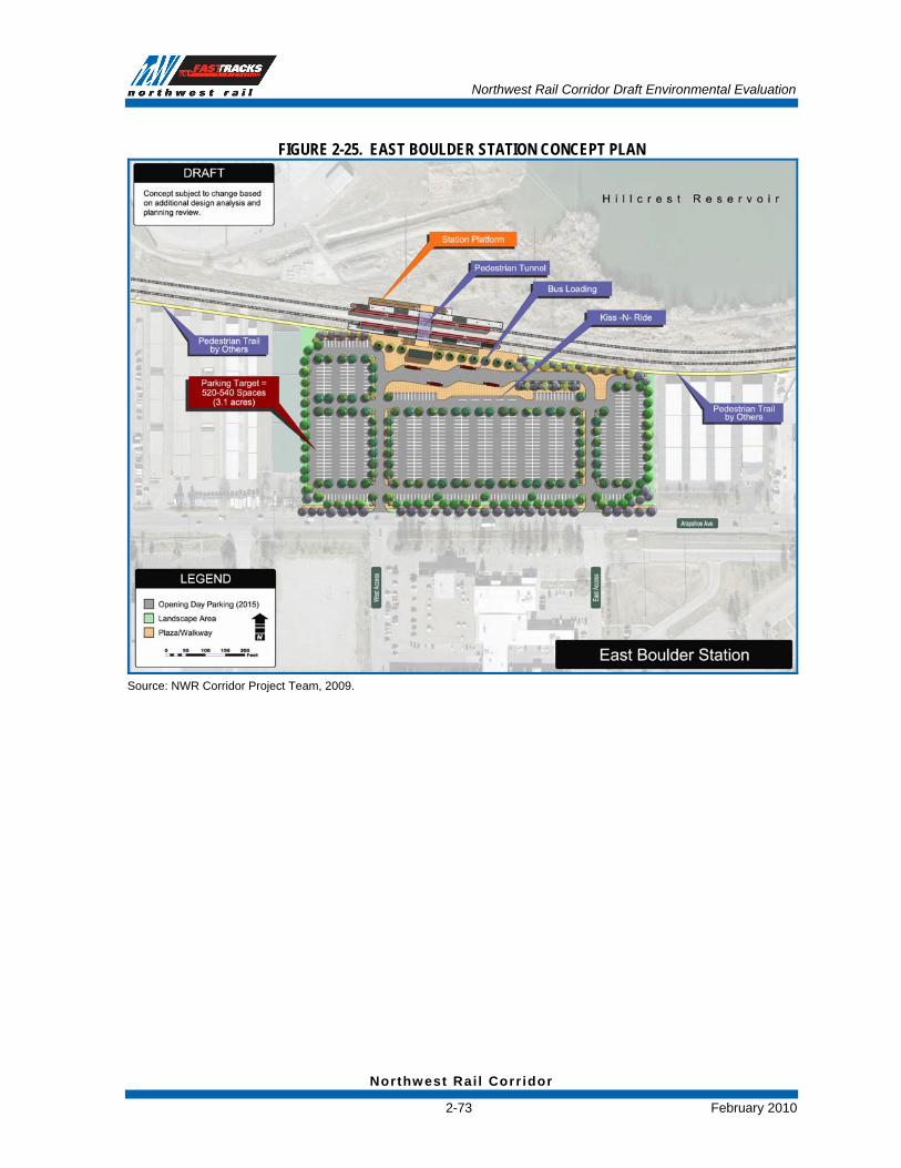
FIGURE 2-25. EAST BOULDER STATION CONCEPT PLAN
Source: NWR Corridor Project Team, 2009.

Northwest Rail Corridor Draft Environmental Evaluation
Northwest Rai l Corr idor
February 2010 2-74
FIGURE 2-26. BOULDER TRANSIT VILLAGE STATION CONCEPT PLAN
Source: NWR Corridor Project Team, 2009.

Northwest Rail Corridor Draft Environmental Evaluation
Northwest Rai l Corr idor
2-75 February 2010
FIGURE 2-27. GUNBARREL STATION CONCEPT PLAN
Source: NWR Corridor Project Team, 2009.

Northwest Rail Corridor Draft Environmental Evaluation
Northwest Rai l Corr idor
February 2010 2-76
FIGURE 2-28. TWIN PEAKS STATION CONCEPT PLAN
Source: NWR Corridor Project Team, 2009.

Northwest Rail Corridor Draft Environmental Evaluation
Northwest Rai l Corr idor
2-77 February 2010
FIGURE 2-29. DOWNTOWN LONGMONT (2015) STATION CONCEPT PLAN
Source: NWR Corridor Project Team, 2009.

Northwest Rail Corridor Draft Environmental Evaluation
Northwest Rai l Corr idor
February 2010 2-78
FIGURE 2-30. DOWNTOWN LONGMONT (2035) STATION CONCEPT PLAN
Source: NWR Corridor Project Team, 2009.
2.4.2.3 Shared-Access Track and Commuter Rail Maintenance Facility The Preferred Alternative would assume the provision of commuter rail transit from DUS in the City and County of Denver to downtown Longmont. Track from the DUS terminal to what is known as the DUS "throat" near Coors Field at Park Avenue was considered a part of the DUS Project. As a result, impacts for this segment of track (DUS to the throat) are presented in the DUS Final Environmental Impact Statement (Final EIS) document. The study area for the NWR EE initiates at the DUS “throat” and extends to the north. The first 3.5 miles of the alignment between the DUS throat and Pecos Street would be shared with the Gold Line Project. The remaining 37.5 miles of track would be dedicated to the NWR Corridor.
The NWR Corridor cannot function without a supporting Commuter Rail Maintenance Facility (CRMF). Therefore, the Preferred Alternative assumes the provision of a CRMF located on the Fox North Site, north of downtown Denver. The CRMF would include facilities to repair, maintain, clean, fuel, and store both DMU and electric multiple unit (EMU) commuter rail trains for the FasTracks commuter rail program. The impacts associated with the CRMF were initially presented in a Supplemental Environmental Assessment (SEA), a supplement to the Gold Line DEIS, which was distributed to the public in April 2009. Both the Gold Line and CRMF projects are discussed in more detail below in Section 2.4.2.7, Projects Linked to

Northwest Rail Corridor Draft Environmental Evaluation
Northwest Rai l Corr idor
2-79 February 2010
the NWR Corridor Project. The CRMF impacts are incorporated here by reference. See Figure 2-31 for a depiction of the location of the CRMF.
2.4.2.4 Operations By 2035 the Preferred Alternative would provide 15-minute service in the morning and evening peak periods from Boulder to Denver and 30-minute service between Longmont and Boulder. Service would be provided at 30-minute headways at most other times throughout the corridor. Peak periods are defined as weekday mornings from 6:00 a.m. to 9:30 a.m. and weekday evenings from 2:30 p.m. to 7:30 p.m.
The operations plan will be optimized as the design progresses such that the project minimizes operational costs while maximizing ridership. The change to the operational plan that is most likely will be the reduction of train frequencies. The reduction of train frequencies would reduce traffic, parking, and noise impacts. Therefore, the train frequencies assumed in this document, represent “worst case” from an environmental impact perspective.
2.4.2.5 Capital and Operating Costs The capital and operating costs of the Preferred Alternative are included in Table 2-20.
TABLE 2-20. CAPITAL AND OPERATING COSTS
Preferred Alternative Element Capital Cost (2008 Dollars)
Annual Operations and Maintenance Cost
(2008 Dollars) NWR Corridor Project with proposed FasTracks stations $641.1 million
Shared Alignment Gold Line/NWR Corridor (DUS to Pecos Street) $261.5 million1
$17.9 million
Four Unfunded Stations $100.3 million2 $2.8 million Total $1.0 billion $20.7 million
Source: NWR Corridor Project Team, 2009. Notes: 1. The cost for the Shared Alignment segment, although illustrated in this estimate, will be funded as a FasTracks program-wide expense since the section from DUS to the Pecos Station will be shared jointly by the Gold Line, and the section from DUS to the Maintenance Facility will be used by the East and North Metro corridors. 2. Proposed unfunded station costs estimate the following capital cost per station: – Westminster/88th Avenue Station: $52.9 million – Broomfield/116th Avenue Station: $13.3 million – East Boulder Station: $22.8 million
– Twin Peaks Station: $11.3 million
2.4.2.6 Phased Implementation This project may be constructed in phases. Phase 1 would include construction from DUS to the South Westminster/71st Avenue Station (approximately Bradburn Boulevard). Phase 1 would be constructed as a component of RTD’s Eagle P3 project. The Eagle P3 is a Public Private Partnership that will conduct final design and build RTD’s East Corridor, Gold Line and this portion of NWR. For Phase 1, RTD would operate on tracks exclusively dedicated to commuter rail transit from DUS to the South Westminster/71st Avenue Station. Future phases constructed beyond the South Westminster/71st Avenue Station would share track and ROW with freight operations and would require an operating easement from the BNSF

Northwest Rail Corridor Draft Environmental Evaluation
Northwest Rai l Corr idor
February 2010 2-80
Railway Company. RTD is currently negotiating the necessary agreements with the BNSF Railway Company. Because the Eagle P3 project includes EMU technology for the Gold Line and East Corridor projects, the Phase 1 Alignment would be electrified from DUS to the South Westminster/71st Avenue Station.
Future phases constructed north of the South Westminster/71st Avenue Station would be DMU. DMU technology would eventually operate seamlessly (sharing the track with the Phase 1 EMU) from DUS to downtown Longmont. See Figure 2-31 for a depiction of the Phase 1 study area.
2.4.2.7 Projects Linked to the NWR Corridor Project Two projects that were conducted concurrently and are linked with the NWR Corridor Project are the Gold Line EIS and the Commuter Rail Maintenance Facility Supplemental Environmental Assessment (CRMF SEA). These proposed projects are to provide commuter rail from DUS in downtown Denver to Ward Road in Wheat Ridge, Colorado for Gold Line, and a CRMF to serve the FasTracks commuter rail system.
Shared Facilities
The CRMF (just north of 48th Avenue in Denver) and the track alignment (from DUS to the CRMF) are shared by all of the FasTracks commuter rail corridors for service at the CRMF and for passenger service for the NWR and Gold Line corridors. North of the CRMF to Pecos Street, the alignment is shared by the NWR and the Gold Line for a continuation of passenger service on those corridors. West of Pecos Street to Ward Road, the Gold Line Project would operate primarily within the existing BNSF Railway Company and Union Pacific Railroad Company ROW.
CRMF SEA
As mentioned above, the CRMF is shared by all four of the FasTracks commuter rail corridors. None of these corridors could function without a maintenance facility. For this reason, the CRMF is considered to be part of the Preferred Alternative for all four of the commuter rail corridors. The CRMF SEA was distributed to the public for comment in April 2009. The impacts documented in the CRMF SEA are incorporated into this NWR EE document by reference.
Gold Line Final EIS and ROD
The Gold Line Final EIS was released for public circulation in August 2009. The Final EIS documents the project activities that have occurred from the close of the Gold Line DEIS public comment period (September 1, 2008) until the completion of the Final EIS and Preliminary Engineering. Part of the finalization process for the Gold Line Final EIS was incorporating updates and comments related to the CRMF as part of the Gold Line Preferred Alternative. Responses to comments on the Gold Line DEIS and the CRMF SEA are included in the Gold Line Final EIS document. Impacts documented in the Gold Line Final EIS for the alignment from DUS to Pecos Street are incorporated in this NWR EE by reference. Subsequently, the Gold Line Project
Team responded to comments on the Final EIS and a ROD was issued by the FTA on November 2, 2009, marking the end of the project's planning process.

Northwest Rail Corridor Draft Environmental Evaluation
Northwest Rai l Corr idor
2-81 February 2010
FIGURE 2-31. PHASE 1 STUDY AREA
Source: NWR Corridor Project Team, 2009.

Northwest Rail Corridor Draft Environmental Evaluation
Northwest Rai l Corr idor
February 2010 2-82
This page intentionally left blank.