table of contents - burlington, vt
TRANSCRIPT

i
TABLE OF CONTENTS
TABLE OF CONTENTS ........................................................................................................... i
Intent Of Specifications .......................................................................................................... 1
Bid Bond ................................................................................................................................. 2
Certificate Of Insurance ......................................................................................................... 2
Delivery .................................................................................................................................. 2
Exceptions .............................................................................................................................. 2
ISO Compliance ..................................................................................................................... 3
Proposal Price ......................................................................................................................... 3
Reference List ......................................................................................................................... 4
Service Requirements ............................................................................................................. 4
Overall Height Restriction ...................................................................................................... 4
Overall Length Restriction ..................................................................................................... 4
NFPA Compliance .................................................................................................................. 4
Equipment Capacity ............................................................................................................... 4
CHASSIS SPECS And PREP .................................................................................................... 4
Kenworth Chassis ................................................................................................................... 4
Kenworth Chassis Prep ......................................................................................................... 12
BUMPERS ............................................................................................................................... 12
Bumper ................................................................................................................................. 12
Bumper Extension ................................................................................................................ 12
Bumper Gravel Shield .......................................................................................................... 12
WHEEL OPTIONS .................................................................................................................. 12
Front And Rear Wheel Trim Package .................................................................................. 12
TIRE OPTIONS ....................................................................................................................... 12
Tire Pressure Indicators ........................................................................................................ 12
AIR SYSTEM OPTIONS ......................................................................................................... 13
Air Inlet ................................................................................................................................ 13
Air Horns .............................................................................................................................. 13
EXHAUST OPTIONS .............................................................................................................. 13
Exhaust End Modification .................................................................................................... 13
BATTERIES ............................................................................................................................. 13
Battery Jumper Stud Location .............................................................................................. 13
Commercial Chassis Battery Relocation .............................................................................. 13
Battery Box ........................................................................................................................... 13
CHASSIS OPTIONS ................................................................................................................ 14
Front Tow Hooks .................................................................................................................. 14
Three (3) Underbody Receivers ........................................................................................... 14
Front Bumper Receiver ........................................................................................................ 14
CAB DOOR OPTIONS ............................................................................................................ 14
Cab Door Interior Striping .................................................................................................... 14
MISC EXTERIOR CAB OPTIONS ........................................................................................ 14
Grover Air Horns .................................................................................................................. 15
Label ``Diesel Fuel Only`` ................................................................................................... 15
SEATS ...................................................................................................................................... 15
Seating Capacity Tag ............................................................................................................ 15
MISC INTERIOR CAB OPTIONS .......................................................................................... 15
Air Horn Lanyard(S) ............................................................................................................ 15

ii
Cab Console .......................................................................................................................... 15
CAB ELECTRICAL OPTIONS ............................................................................................... 15
Cab Dome Lights .................................................................................................................. 15
Battery Charger Receptacle .................................................................................................. 16
Antenna Base (Qty 2) ........................................................................................................... 16
Battery Charger .................................................................................................................... 16
BODY SPEC ............................................................................................................................ 16
Stainless Steel Rescue Body Design And Construction ....................................................... 16
RESCUE BODY LOWER ....................................................................................................... 17
Body Dimensions ................................................................................................................. 17
Transverse Compartment Floor Extension ........................................................................... 18
RESCUE BODY UPPER ......................................................................................................... 18
Perimeter Roof Center Rear, Entrance From Rear Ladder ................................................... 18
Upper Roof Top Compartment Arrangement ....................................................................... 18
RESCUE BODY REAR ........................................................................................................... 19
Rear Panel Compartments .................................................................................................... 20
Rear Tail Board .................................................................................................................... 20
Rear Body Trim .................................................................................................................... 20
Recessed Step Area .............................................................................................................. 20
RESCUE BODY OPTIONS ..................................................................................................... 20
Awning Side Body (Qty 2) ................................................................................................... 20
DOORS ..................................................................................................................................... 21
Painted Roll Up Compartment Door .................................................................................... 21
Single Drop-Down Compartment Door B2 .......................................................................... 21
Stainless Steel Double Compartment Doors B1 ................................................................... 22
SHELVES ................................................................................................................................. 23
Adjustable Shelf [Qty: 2] ...................................................................................................... 23
Unistrut Tracking .................................................................................................................. 23
COMPARTMENT DIVIDERS ................................................................................................ 23
Partition Vertical Bolt-In B1 ................................................................................................ 23
Compartment Instructions B1 ............................................................................................... 23
TRAYS / TOOLBOARDS ....................................................................................................... 23
Floor Mounted Roll Out Trays (Qty 4) ................................................................................ 23
Adjustable Roll-Out Tray ..................................................................................................... 24
Roll-Out/Tilt Down Tray (Qty 2) ......................................................................................... 24
Toolboard [Qty: 2] ................................................................................................................ 24
LADDER STORAGE / RACKS .............................................................................................. 25
Adjustable Ladder Brackets ................................................................................................. 25
HANDRAILS / STEPS ............................................................................................................ 25
Rescue Body Access Ladder ................................................................................................ 25
MISC BODY OPTIONS .......................................................................................................... 26
Mud Flaps ............................................................................................................................. 26
Body Fender Panels .............................................................................................................. 26
Stainless Steel Rubrails, Sides Of Body ............................................................................... 26
Trench Panel Storage Module .............................................................................................. 26
Riser, Light Tower ................................................................................................................ 26
Floor Pass-Thru .................................................................................................................... 27
Louvers Wall ........................................................................................................................ 27
CASCADE SYSTEM/FILL STATIONS ................................................................................. 27
4 Bottle Breathing Air Cascade System, DOT 6000 PSI ..................................................... 27

iii
Spacesaver 2-Bottle Fill Station ........................................................................................... 29
SCBA BOTTLE STORAGE .................................................................................................... 29
Zico SCBA Storage Rack Large [Qty: 18] ........................................................................... 29
SCBA Strap .......................................................................................................................... 29
SCBA Storage ...................................................................................................................... 30
ELECTRICAL SYSTEMS ....................................................................................................... 30
Multiplex Electrical System ................................................................................................. 30
Electrical System .............................................................................................................. 30
Multiplex System .............................................................................................................. 30
Wiring ............................................................................................................................... 31
Wiring Protection ............................................................................................................. 31
Wiring Connectors ............................................................................................................ 31
NFPA Required Testing Of Electrical System ................................................................. 32
NFPA Required Documentation ....................................................................................... 32
Vehicle Data Recorder ......................................................................................................... 33
Occupant Detection System ............................................................................................. 33
Multiplex Display ................................................................................................................. 33
Electrical Connection Protection .......................................................................................... 34
LIGHT BARS ........................................................................................................................... 34
Light Bar ............................................................................................................................... 34
Light Bar Mount ................................................................................................................... 34
WARNING LIGHT PACKAGES ............................................................................................ 35
Lower Level Warning Light Package ................................................................................... 35
ADDITIONAL WARNING LIGHTS ...................................................................................... 35
Warning Lights (Qty 4) ........................................................................................................ 35
Hazard (Door Ajar) Light ..................................................................................................... 35
SIRENS .................................................................................................................................... 35
Electronic Siren .................................................................................................................... 36
SPEAKERS .............................................................................................................................. 36
Siren Speaker ........................................................................................................................ 36
DOT LIGHTING ...................................................................................................................... 36
License Plate Light ............................................................................................................... 36
Tail Lights ............................................................................................................................ 36
Turn Signals .......................................................................................................................... 36
Body Marker Lights ............................................................................................................. 37
LIGHTS - COMPARTMENT, STEP & GROUND ................................................................ 37
Compartment Light Package ................................................................................................ 37
Ground Lights ....................................................................................................................... 38
Step Lights ............................................................................................................................ 38
LIGHTS - DECK AND SCENE .............................................................................................. 38
Scenelights Qty (6) ............................................................................................................... 38
Deck/Scene Light Wired To Back-Up Lights ...................................................................... 39
LIGHTS - NON-WARNING ................................................................................................... 39
Engine Compartment Light .................................................................................................. 39
CAMERAS / INTERCOM ....................................................................................................... 39
Camera Back-Up .................................................................................................................. 39
MISC ELECTRICAL ............................................................................................................... 39
Trailer Hitch Pre-Wire Harness ............................................................................................ 39
Back-Up Alarm .................................................................................................................... 40
12 Volt DC Power Distribution Modules (Qty2) ................................................................. 40

iv
Refrigerator ........................................................................................................................... 40
GENERATOR .......................................................................................................................... 41
15KW Direct Drive Generator ............................................................................................. 41
Rating And Capacity ........................................................................................................ 41
Driveline ........................................................................................................................... 41
Generator Controls ........................................................................................................... 41
Gauge Panel ...................................................................................................................... 41
GENERATOR TEST ............................................................................................................... 42
3rd Party Generator Testing ................................................................................................. 42
BREAKER BOXES ................................................................................................................. 42
Circuit Breaker Panel ........................................................................................................... 42
LIGHT TOWERS ..................................................................................................................... 42
Light Tower .......................................................................................................................... 42
Back Light Option ................................................................................................................ 43
RECEPTACLES ....................................................................................................................... 43
Receptacles 20 Amp (Qty 2) ................................................................................................ 43
Receptacles 20 Amp (Qty 2) ................................................................................................ 44
Receptacles 15 Amp (Qty 2) ................................................................................................ 44
Receptacle ............................................................................................................................. 44
MISC LOOSE EQUIPMENT .................................................................................................. 44
DOT Required Drive Away Kit ........................................................................................... 44
EXTERIOR PAINT .................................................................................................................. 44
Commercial Cab Paint .......................................................................................................... 44
Paint Stainless Steel Rescue Body ....................................................................................... 44
Undercoating ........................................................................................................................ 45
LETTERING ............................................................................................................................ 45
Sign Gold Letter [Qty: 100] ................................................................................................. 45
Sign Gold Letters [Qty: 20] .................................................................................................. 45
Lettering Shade And/Or Outline [Qty: 118] ......................................................................... 46
STRIPING ................................................................................................................................ 46
Cab And Body Stripe ............................................................................................................ 46
Cab And Body Stripe [Qty: 2] .............................................................................................. 46
Rear Body Scotchlite Striping .............................................................................................. 46
Front Bumper Scotchlite Striping ......................................................................................... 46
Designated Standing / Walking Area Indication .................................................................. 46
GRAPHICS .............................................................................................................................. 46
Customer Supplied Logo [Qty: 2] ........................................................................................ 47
WARRANTY / STANDARD & EXTENDED ........................................................................ 47
Standard 1 Year Warranty .................................................................................................... 47
10 Year Paint And Corrosion Warranty ............................................................................... 47
Warranty 20 Year Structural ................................................................................................ 47
SUPPORT, DELIVERY, INSPECTIONS AND MANUALS................................................. 47
Electronic Manuals ............................................................................................................... 47
Fire Apparatus Safety Guide ................................................................................................ 48
DEALER ADDED EQUIPMENT ........................................................................................... 48
Dealer ................................................................................................................................... 48

Specification for: CITY OF BURLINGTON FIRE DEPARTMENT
1
BIDDER
COMPLIES
YES NO
Intent of Specifications
It is the intent of these specifications to clearly describe the furnishing and delivery to the
Purchaser, a complete apparatus equipped as specified. The primary objective of these
specifications is to obtain the most acceptable apparatus for service in the Fire Department.
These specifications cover specific requirements as to the tests the apparatus must conform,
together with certain details as to finish, material preferences, equipment and appliances with
which the bidder should conform.
PLEASE NOTE:
These specifications are not meant to be specific to any one manufacturer, but are meant to
establish a minimum quality level against which the purchaser shall compare all proposals for
accuracy, warranty, service and the estimated apparatus life cycle. Alternate body materials
such as aluminum, built using an extruded aluminum method of construction, may be
considered. Steel bodies, aluminum bodies built on a steel sub-frame, or bent and formed body
construction shall not meet the intent of these specifications.
The design of the apparatus must embody the latest approved automotive design practices. The
workmanship must be of the highest quality in its respective field. Special consideration shall be
given to service access to areas needing periodic maintenance, ease of operation, and
symmetrical proportions. Construction must be heavy-duty and ample safety factors must be
provided to carry loads as specified. The construction method employed will be in such a
manner as to allow ready removal of any component for service or repair.
The apparatus shall conform to the National Fire Protection Association Standard for
Automotive Fire Apparatus, number 1901, in its most recent edition, unless otherwise specified
in this document. Only the specified firefighting support equipment listed in these specifications
shall be provided.
The apparatus shall further conform to all Federal Motor Vehicle Safety Standards. No
exception.
Each bidder shall furnish satisfactory evidence of their ability to design, engineer, and construct
the apparatus specified and shall state the location of the factory producing the apparatus. They
shall also substantiate they are in a position to render prompt and proper service and to furnish
replacement parts for the apparatus.
Each bid must be accompanied by a set of detailed contractor's specifications consisting of a
detailed description of the apparatus and equipment proposed. All bid proposal specifications
must be in the same sequence as the advertised specification for ease of comparison. These
specifications shall include size, location, type, and model of all component parts being
furnished. Detailed information shall be provided on the materials used to construct all facets of
the apparatus body. Any bidder who fails to submit detailed construction specifications, or who
photo copies and submits these specifications as their own construction details will be
considered non-responsive and shall render their proposal ineligible for award. No exception.
Proposals will be addressed and submitted in accordance with the instructions provided on the
cover sheet. The words ''Fire Apparatus Proposal'', the due date, and opening time if any shall be
stated on the front of the envelope.

Specification for: CITY OF BURLINGTON FIRE DEPARTMENT
2
BIDDER
COMPLIES
YES NO
It shall be the responsibility of the bidder to assure that their proposal arrives at the location and
time indicated. Late proposals, telegrams, facsimile, or telephone bids will not be considered.
No exception.
All bidders are required to propose payment terms as invoiced and due at time of delivery. No
required prepayments or progress payments are to be required.
Bid Bond
A bid security in the form of a Bid Bond, cashier's check, or certified check made payable to the
Purchaser in the amount of ten percent (10%) of the total bid shall be required. This shall serve
as a guarantee which may be forfeited and retained by the Purchaser in lieu of its other legal
remedies if a successful bidder's proposal is accepted by the Purchaser and the bidder shall fail
to execute and return to the Purchaser the required contract and bonds within ten (10) days after
delivery. If a Bid Bond is provided, it shall be issued by a bonding company licensed to bond in
this State.
Certificate of Insurance
Each bidder shall furnish, with their proposal, a Certificate of Product Liability Insurance for a
minimum of ten (10) million dollars. Failure to provide this documentation shall render the
proposal non-responsive and the bid shall be rejected. This certificate shall be from the prime
builder only. Certificates submitted from various sub-contractors in order to total the ten million
dollar minimum will not be acceptable as meeting the requirements of this section.
If one of the major portions of the apparatus (i.e. chassis, aerial, or body) is not designed,
fabricated, and assembled by the prime builder, a separate Certificate of Liability Insurance for
a minimum of ten (10) million dollars must be provided by each additional contractor.
The Certificate must be made out to the Purchaser and must be original. Submission of a non-
original Certificate, or a Certificate provided that is not made out to the Purchaser, will not meet
the requirements of this section.
Delivery
The bidder shall state the time required for delivery of the completed unit on the proposal page.
The completed unit shall be delivered to the purchaser with familiarization instructions provided
to Fire Department personnel on operation, care and maintenance of apparatus at the purchaser's
location.
Exceptions
The following apparatus specifications are considered minimum design and construction
standards against which the apparatus will be inspected. It is the intent to receive proposals on
equipment/apparatus meeting the attached detailed specifications in their entirety. Any
proposals being submitted, without ''Full Compliance'' with these specifications, shall so state on
the bid proposal page, followed by a detailed ''Letter of Exceptions'' listing the areas of non-

Specification for: CITY OF BURLINGTON FIRE DEPARTMENT
3
BIDDER
COMPLIES
YES NO
compliance. The reference must include page number, paragraph, and the exact nature of the
exception.
Failure to follow this format, provided for the convenience of the Purchaser, will render the
vendor's proposal non-responsive and ineligible for award of contract.
The Purchaser may add the statement ''No Exception'' to a component or design feature in these
specifications. In the interest of fleet conformity or specific performance requirements, the
Purchaser will not permit exceptions taken to these item(s).
The Purchaser reserves the right to reject any or all bid proposals and purchase the equipment it
deems most suitable to its needs. The Purchaser does not, in any way, obligate itself to accept
the lowest or any bid. Any bidder taking total exception to the complete specification or a major
element will result in immediate rejection of the proposal.
ISO Compliance
The manufacturer shall operate a Quality Management System meeting the requirements of ISO
9001:2000.
The International Organization for Standardization (ISO) is a recognized world leader in
establishing and maintaining stringent manufacturing standards and values. The
manufacturer’s certificate of compliance affirms that these principles form the basis for a quality
system that unswervingly controls design, manufacture, installation, and service.
The manufacturer’s quality systems shall consist of, but not be limited to, all written quality
procedures (aka QOP) and other procedures referenced within the pages of the manufacturer’s
Quality Manual, as well as all Work Instructions, Workmanship Standards, and Calibration
Administration that directly or indirectly impacts products or processes. In addition, all
apparatus assembly processes shall be documented for traceability and reference. The
manufacturer shall also engage the services of a certified third party for testing purposes where
required.
If the manufacturer operates more than one manufacturing facility each facility must be ISO
certified.
By virtue of its ISO compliance the manufacturer shall provide an apparatus that is built to
exacting standards, meets the customer’s expectations, and satisfies the customer’s
requirements.
A copy of the manufacturer’s certificate of ISO compliance for each manufacturing facility shall
be provided with the bid.
Proposal Price
Each bidder's proposal must include all items required in the specifications unless a specific
exception is taken. Any bidder who option prices an item included in these specifications that

Specification for: CITY OF BURLINGTON FIRE DEPARTMENT
4
BIDDER
COMPLIES
YES NO
does not specifically require option pricing will have their proposal rejected without further
cause.
Reference List
Each bid shall be accompanied by a list of at least twenty-five (25) similarly constructed
apparatus presently in service. Each reference must be apparatus built of the same construction
style as these specifications call for. This list shall include customers’ names, addresses and date
apparatus was placed in service.
Service Requirements
Each bidder shall supply, with their proposal, detailed information on the bidder's ability to
perform routine and emergency service on the apparatus after delivery. Detailed information
shall be provided on service facilities, personnel, service vehicles, and the type and nature of
repair work the bidder is able to provide. Bidder shall state the number of miles from the
Purchaser's facility to the nearest fully staffed repair facility operated by the bidder. It is the
intent of the Purchaser to assure that parts and service are readily available for the equipment
specified. Service capabilities will be one of the criteria for award of this contract.
Overall Height Restriction
The apparatus shall have overall height restrictions (unloaded condition) of 10 ft 9 inches.
Overall Length Restriction
The completed unit shall have an overall length restriction 31 feet.
NFPA Compliance
The supplied components of the apparatus shall be compliant with NFPA 1901, 2016 edition.
Equipment Capacity
Equipment allowance on the apparatus shall be 4000 lbs. This allowance is in addition to the
weight of the cascade system and ladders listed in this document.
CHASSIS SPECS and PREP
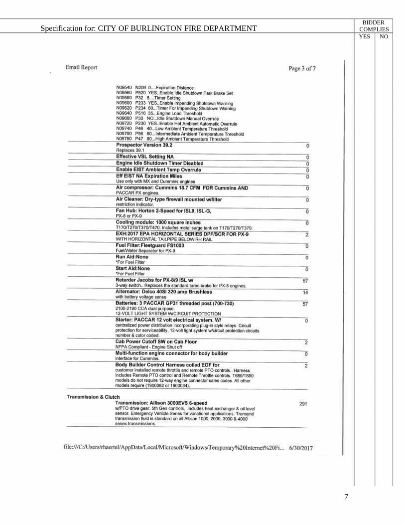
Kenworth Chassis
The commercial chassis specifications are as follows:

Specification for: CITY OF BURLINGTON FIRE DEPARTMENT
5
BIDDER
COMPLIES
YES NO

Specification for: CITY OF BURLINGTON FIRE DEPARTMENT
6
BIDDER
COMPLIES
YES NO
Specification for: CITY OF BURLINGTON FIRE DEPARTMENT
7
BIDDER
COMPLIES
YES NO

Specification for: CITY OF BURLINGTON FIRE DEPARTMENT
8
BIDDER
COMPLIES
YES NO

Specification for: CITY OF BURLINGTON FIRE DEPARTMENT
9
BIDDER
COMPLIES
YES NO

Specification for: CITY OF BURLINGTON FIRE DEPARTMENT
10
BIDDER
COMPLIES
YES NO

Specification for: CITY OF BURLINGTON FIRE DEPARTMENT
11
BIDDER
COMPLIES
YES NO

Specification for: CITY OF BURLINGTON FIRE DEPARTMENT
12
BIDDER
COMPLIES
YES NO
Kenworth Chassis Prep
The commercial chassis shall be made ready for installation of components required by the fire
apparatus specifications such as warning lights and sirens, cab wire harness, etc. Preparation
shall also include relocating of components as necessary to meet the fire apparatus requirements
such as exhaust tail pipe, air system components, batteries, etc.
BUMPERS
Bumper
A heavy duty 10" high steel channel type front bumper shall be provided. The front corners of
the bumper shall be angled to reduce swing clearance. The bumper shall be painted job color.
Bumper Extension
The front bumper extension shall be approximately 12” from the face of the cab as required.
Bumper Gravel Shield
The extended front bumper gravel shield shall be made of 3/16” (.375”) aluminum tread
plate material.
WHEEL OPTIONS
Front and Rear Wheel Trim Package
The front and Rear aluminum wheels shall have stainless steel lug nut covers. The front axle
shall be covered with American made Real Wheels brand mirror finish, 304L grade, non-
corrosive stainless steel universal baby moons. The rear axle shall be covered with American
made Real Wheels brand mirror finish, 304L grade, non-corrosive stainless steel high hats. All
stainless steel components shall carry a lifetime warranty plus a 2 year re-buffing policy. There
shall be two (2) baby moons, (2) high hats and forty (40) lug nut covers.
TIRE OPTIONS
Tire Pressure Indicators
The apparatus shall be provided with Real Wheels AirGuard LED tire pressure indicating valve
stem caps. When the tire is under inflated by 5-10 PSI, the LED indicator on the cap shall flash
red. The indicator housings shall be shock resistant and constructed from polished stainless
steel. The indicators shall be calibrated by attaching to valve stem of a tire at proper air pressure
per load ratings and easily re-calibrated by simply removing and re-installing them during
service.

Specification for: CITY OF BURLINGTON FIRE DEPARTMENT
13
BIDDER
COMPLIES
YES NO
AIR SYSTEM OPTIONS
Air Inlet
A 1/4” male plug air hose inlet shall be connected to the air reservoir tank. A 1/4” inline check
valve will be installed in the line. Air hose connection will provide the capability of filling the
air brake system with air from an outside source. Location: driver's door step area.
Air Horns
Dual Grover hood mounted air horns shall be installed.
EXHAUST OPTIONS
Exhaust End Modification
The end of the exhaust tail pipe shall be modified to accommodate a Plymovent in-house
exhaust extraction system. The tail pipe will be at 90 degrees and straight out below the officer
side of body in front of the rear wheels. A stop ring shall be provided on the tail pipe to properly
position the Plymovent nozzle.
BATTERIES
Battery Jumper Stud Location
Auxiliary battery jumper studs shall be located near the cab to allow external battery charging.
Commercial Chassis Battery Relocation
Batteries shall be placed on non-corrosive rubber matting and shall be located on the forward
driver side top of the body, above the cascade bottles. The batteries shall be secured with hold-
down brackets to prevent movement, vibration, and road shock. The hold-down bracket J-hooks
shall be cut to fit and shall have all sharp edges removed. The batteries shall be placed in plastic
trays to provide preliminary containment should there be leakage of hazardous battery fluids.
There shall be two (2) plastic trays, each containing (2) batteries (if applicable). Each battery
tray shall be equipped with a rubber vent hose to facilitate drainage. The rubber vent hose shall
be routed to drain beneath the battery box.
Battery Box
There shall be a diamond plate battery box enclosing the batteries for protection. Cover shall
include ventilation louvers.

Specification for: CITY OF BURLINGTON FIRE DEPARTMENT
14
BIDDER
COMPLIES
YES NO
CHASSIS OPTIONS
Front Tow Hooks
Two (2) heavy duty painted front tow hooks shall be securely bolted to the front chassis frame
rail extensions to allow towing (not lifting) of the apparatus without damage. They shall be
mounted in the downward position.
Three (3) Underbody Receivers
An underbody three (3) way receiver assembly with (3) winch connections shall be provided.
There shall be three (3) receivers provided below the rear of the body; one (1) rear facing
winch/Class IV hitch receiver and two (2) Class III side facing winch receivers. The
receivers shall be of an integral construction to the underbody support assembly.
The rearward facing Class IV hitch/winch receiver shall include two (2) tow eye connections
and an electrical connection for a portable winch application. The two (2) side facing winch
receivers shall be located one (1) each side below the rearward most body compartment. Each
side facing hitch receiver shall include an electrical connection for a portable winch application.
Rear receiver shall be rated as a Class IV trailer hitch with a 10,000 lb. gross trailer weight with
a 1000 lb. max trailer tongue weight.
Each side facing portable winch connection shall be rated for a maximum of 9,000 lb. straight
line pull.
Front Bumper Receiver
A front bumper winch receiver shall be provided. The receiver shall be constructed of steel
tubing and attached to the chassis framing. An electrical connection shall be provided for use
with a portable winch.
The portable winch connection shall be rated for a 9,000 pound straight line pull.
CAB DOOR OPTIONS
Cab Door Interior Striping
Reflective striping shall be installed on commercial cab doors, visible when the door is open,
meeting NFPA requirement of 96 sq. in. coverage for each door.
MISC EXTERIOR CAB OPTIONS

Specification for: CITY OF BURLINGTON FIRE DEPARTMENT
15
BIDDER
COMPLIES
YES NO
Grover Air Horns
Dual Grover air horns shall be provided and connected to the chassis air system. The horns shall
be mounted on the hood of the chassis. A pressure protection valve shall be installed to prevent
the air brake system from being depleted of air pressure
Label ``Diesel Fuel Only``
Located above each fuel filler housing shall be a metallic label that designates ”Diesel Fuel
Only” requirements. It shall be black with white or equivalent contrasting letters a minimum of
1/2” high.
SEATS
Seating Capacity Tag
A tag that is in view of the driver stating seating capacity of two (2) personnel shall be provided.
MISC INTERIOR CAB OPTIONS
Air Horn Lanyard(s)
There shall be a “Y” style lanyard mounted in the center of the cab to a single switch that allows
the driver and officer to operate the air horns on units thus equipped. The lanyard shall activate
a single center mounted electrical air switch.
Cab Console
The console shall be centrally located and shall allow the driver and/or officer access to all
components while seated with seat belts secured.
The console shall be constructed of aluminum smooth plate with a black Zolatone finish. The
top surface shall have a non-reflective material for increased visibility of labels and controls.
Any switches located on the console shall be clearly labeled and shall be back-lit for easy
operation and visibility.
CAB ELECTRICAL OPTIONS
Cab Dome Lights
A dome light assembly with two incandescent bulbs with one white lens and one red lens and
plastic housing shall be installed. The white lights activate with appropriate cab door and light
assembly mounted push button switch, the red light activates with light assembly mounted push
button switch only.

Specification for: CITY OF BURLINGTON FIRE DEPARTMENT
16
BIDDER
COMPLIES
YES NO
The lights shall be mounted in the front of the cab, one in the driver and one in the officer
ceiling.
Battery Charger Receptacle
A 20 amp battery charger receptacle shall be installed below the driver door in the step area.
The cover color shall be Yellow.
Antenna Base (Qty 2)
There shall be a Tessco P/N 90942 universal antenna base mounted on the each side (qty 2) of
the cab roof using weatherproof connectors. The antenna base shall be NMO Motorola
Style (equivalent to a MATM style) with RG58U coax cable. The coaxial cable shall terminate
in the center console.
Battery Charger
An LPC 20 battery charger with remote mounted LED display shall be installed.
A fully automatic charging system shall be installed on the apparatus. The system shall have a
120 volt, 60 hertz, 7 amp AC input with an output of 20 amps 12 volts DC. The battery charging
system shall be connected directly to the shoreline to ensure the batteries remain fully charged
while the vehicle is in the fire station or firehouse.
The system shall include a remote charging status indicator panel. The panel shall consist of two
(2) LED lights to provide a visual signal if battery voltage is good or drops below 11.5 volts.
The microprocessor shall be continuously powered from the battery to provide the charge status.
BODY SPEC
Stainless Steel Rescue Body Design And Construction
The compartment floors, ceilings, front panels, vertical side sheets, rear walls, door openings,
wheel wells, compartment panels, dividing walls, and reinforcements shall be constructed of 12
gauge 304L stainless steel material.
To eliminate unnecessary seams and overlapping areas, the construction of all component panels
shall feature break-formed fabrication. Angle iron framing is not acceptable. Component
panels shall be in single metal sections wherever possible.
The assembly of body component panels shall be with inert gas, continuous feed welders. Stick
welding is not acceptable. The use of sheet metal fasteners in assembly of body components is
unacceptable.

Specification for: CITY OF BURLINGTON FIRE DEPARTMENT
17
BIDDER
COMPLIES
YES NO
Structural supports shall be incorporated into the overall design to provide the necessary support
for component panels and body modules.
The body shall be a free standing module supported only by the top of the chassis frame rails
using a transverse 7 gauge 304L stainless steel structure assembly consisting of 2" x 3" tubes
and 3/16” mounting plates. This structure shall be secured in a minimum of eight (8) locations,
using a double flex mount system with angle brackets bolted to both the body structural
assembly and the sides of the chassis frame rails using Grade 8 fasteners. Mylar shall be used to
isolate the structural assembly from the frame rails. A body substructure using carbon steel,
outrigger arms or any other mounting method is not acceptable. This design is required to
eliminate shift and stress on the body module and component panels.
Each compartment door opening shall have at least a double break-formed door jamb for
recessed door seal inboard of the exterior of the body. The break-formed door jamb is required
for superior strength and body construction integrity. Doors that utilize only a single break-
formed door jamb are not acceptable.
The compartment floor construction shall permit easy cleaning with a true sweep-out design.
The outer floor area, making up the compartment door jamb, shall incorporate triple break-
formed construction for recessed door seal inboard of the exterior of the body. This shall be
required to eliminate road splash and debris from entering the compartments at floor level.
Angles, lips, or door moldings are not acceptable in the base of the door opening. There shall be
a minimum of two (2) 3/8" drain holes in each of the compartment floors.
The interior of all compartments shall have a machine sanded DA finish that shall not be
painted. Each interior compartment seam shall be sealed with a silver silicone caulk. The rear
walls of each compartment shall be provided with a bright stainless steel louvered vent.
RESCUE BODY LOWER
Body Dimensions
Left Side Body Compartments
Compartment L1, directly behind the cab, shall be 52.0" wide x 80.0" high x 27.0" deep in the
lower section and transverse over the frame rails to R1 with one (1) rollup door.
Compartment L2, directly ahead of the rear wheels, shall be 52.0" wide x 80.0" high x 27.0"
deep in the lower section and transverse over the frame rails to R2 with one (1) rollup door.
Compartment L3, above the rear wheels, shall be 60.0" wide x 48.7" high x 27.0" deep with a
solid rear wall and one (1) rollup door.
Compartment L4, behind the rear wheels, shall be 52.0" wide x 80.0" high x 27.0" deep, full
height, with a solid rear wall and one (1) rollup door.

Specification for: CITY OF BURLINGTON FIRE DEPARTMENT
18
BIDDER
COMPLIES
YES NO
Right Side Body Compartments
Compartment R1, directly behind the cab, shall be 52.0" wide x 80.0" high x 27.0" deep in the
lower section and transverse over the frame rails to L1 with one (1) rollup door.
Compartment R2, directly ahead of the rear wheels, shall be 52.0" wide x 80.0" high x 27.0"
deep in the lower section and transverse over the frame rails to L2 with one (1) rollup door.
Compartment R3, above the rear wheels, shall be 60.0" wide x 48.7" high x 27.0" deep with a
solid rear wall and one (1) rollup door.
Compartment R4, behind the rear wheels, shall be 52.0" wide x 80.0" high x 27.0" deep, full
height, with a solid rear wall and one (1) rollup door.
Transverse Compartment Floor Extension
The floor at the frame height in L1, L2, R1 and R2 shall be extended to the door opening. The
floors are made from 12 gauge 304L stainless steel. Floor extensions shall be welded in place.
RESCUE BODY UPPER
Perimeter Roof Center Rear, Entrance From Rear Ladder
A perimeter roof at the top of body is designed to allow for storage and a walking area on top of
the truck. Entrance is at the rear on the curb side of the truck. There is a 30 inch wide aisle way
that runs between two (2) sets of roof compartments. The aisle shall have LED lights along the
walk way. The walkway ends at a top open transverse storage area at the front of the body.
Upper Roof Top Compartment Arrangement
Front Upper Body Transverse Storage Pocket
The front of the upper body header area shall be designed to provide a 66" long transverse
storage pocket for protected and concealed installation of a light tower and cascade bottles.
To prevent accumulation of water, the non-slip aluminum tread plate floor of this area shall be
provided with large drain holes and drainage tubing properly installed to discharge water down
and out of the body. The overall height and design of this transverse storage pocket shall
seamlessly blend with the remainder of the upper body header area.
Upper Body Compartments
Above the left and right side full depth rescue body compartments, rearward of the storage
pocket, shall be additional full length horizontal top loading storage compartments separated by
the 30 inch wide center aisle way. These compartments shall be constructed of 12 gauge 304L
stainless steel, formed and welded integral with the main body compartments, and shall not

Specification for: CITY OF BURLINGTON FIRE DEPARTMENT
19
BIDDER
COMPLIES
YES NO
appear as add-on compartments. There shall be divider panels between the drivers side upper
compartments only ( No Divider in Officers side). The finished overall body height shall closely
blend with the cab roof height for best appearance. The compartments shall be 23” high x 33"
wide and have the following lengths;
Driver side front compartment 104"
Driver side rear compartment 58"
Officer side front compartment 69"
Officer side rear compartment 69"
All dimensions are approximate.
The outer full length panel of these compartments shall provide room for installation of side and
rear Upper Zone warning lights, floodlighting, and body lettering.
Aisleway
Between the upper compartments shall be a 30" wide center aisle way. The floor of the aisle
way shall be stainless steel located above the tops of the lower center body area
compartments. For safe footing in all weather conditions, maintenance free Duradek T3500
slatted fiberglass non-skid yellow decking shall be installed on top of the flooring, full length
and width of the aisle way. Included shall be two (2) 4-1/2" diameter Truck-Lite LED recessed
clear lens lights for proper illumination of the aisle way, wired to come on with the cab
controlled step light or ground light switch.
Hatch Doors
The left and right side upper compartments shall each be equipped with top opening 3/16"
polished aluminum treadplate reinforced hatch style doors, hinged outboard, latching at the
center aisle way. A full perimeter formed raised lip door jamb shall be provided on the top of
the compartments for each door, and shall include a hollow core neoprene gasket on the doors
for a complete water tight seal.
To assist opening and closing the doors, each door shall include a chrome plated handle,
centered on the doors latching end for easy single hand operation. Each door shall have rubber
hood latch hold downs and two heavy duty gas tube hold open arms.
Two (2) recessed clear lens Whelen Model 5GC0CCCR LED (or equivalent) lights shall be
installed in each compartment. Lights will be bracket mounted under lid. Each lid shall be
wired to the door ajar indicator in the cab.
RESCUE BODY REAR

Specification for: CITY OF BURLINGTON FIRE DEPARTMENT
20
BIDDER
COMPLIES
YES NO
Rear Panel Compartments
The upper rear compartment B1, above chassis frame rails, shall be 45" wide x 57" high x 116"
deep with two box style (2) hinged doors.
Lower compartment B2, between the full length chassis frame rails, shall be 24" wide x 15"
high x 26" deep, with a smooth aluminum bottom hinged drop-down door and stainless steel
bent D-ring latch. The smooth aluminum material shall be an ideal surface for Chevron graphics
or as required. Rubber bumpers shall be installed on the face of the door where the open door
contacts the rear tailboard.
Rear Tail Board
A 3/16" non-skid aluminum treadplate rear step assembly shall be installed. Rear step outside
flanges shall be formed down a minimum of 2-1/2" and formed inward 1" for rigidity. The rear
tailboard shall be full width of the body supported by 12 gauge stainless steel channels, spaced
away for drainage and 12" deep. The step shall have Bustin Tread non-skid aluminum inserts
welded flush with the pattern of the treadplate for safe footing.
Rear Body Trim
The rear body panel shall be trimmed with 1/8" FRP panels that are painted job color.
Recessed Step Area
The rear right side above the Zico access ladder is recessed in 24" for access to the top of the
roof top compartments. The recessed area is approximately 20.5" wide and the stepping area
shall be embossed diamond plate.
RESCUE BODY OPTIONS
Awning Side Body (Qty 2)
A side body awning, approximately 19` long x 10` wide, shall be installed on each side of the
vehicle. The arms shall be attached to the vertical body extrusions allowing an unobstructed
walking area underneath the awning.
The canopy is woven of a tough acrylic fabric to resist rotting, cracking, and mildew, available
in a variety of colors.
A wrap around slatted metal enclosure secures the awning to the vehicle while traveling and will
minimize dirt and grime on the canopy.
Awning color will be Gray.

Specification for: CITY OF BURLINGTON FIRE DEPARTMENT
21
BIDDER
COMPLIES
YES NO
Awning will be connected to the door system to indicate when it is deployed.
DOORS
Painted Roll Up Compartment Door
A ROM brand roll up door painted job color shall be provided on all side body compartments.
The Robinson door slats shall be double wall box frame and manufactured from anodized
aluminum. The slats shall have interlocking end shoes on each slat. The slats shall have
interlocking joints with a PVC/vinyl inner seal to prevent any metal to metal contact and inhibit
moisture and dust penetration.
The track shall be painted aluminum with a finishing flange incorporated to provide a finished
look around the perimeter of the door without additional trim or caulking. The track shall have a
replaceable side seal to prevent water and dust from entering the compartment.
The doors shall be counterbalanced for ease in operation. A full width latch bar shall be
operable with one hand, even with heavy gloves. Securing method shall be a positive latch
device.
A magnetic type switch integral to the door shall be supplied for door ajar indication and
compartment light activation.
Single Drop-Down Compartment Door B2
A single compartment door shall be constructed using a box pan configuration with sanded
exterior finish shall be installed on compartment B2. The outer door pan shall beveled and shall
be constructed from 3/16” (0.188”) aluminum smooth plate. Inner door pan shall be constructed
from 3/32" (0.090”) smooth aluminum plate and shall have nutsert fittings to attach hold-open
hardware. The inner pan shall have a 95-degree bend to form an integral drip rail.
The compartment door shall have a 1” x 9/16” (1” x 0.43”) closed-cell ”P” EPDM sponge
gasket meeting ASTM D-1066 2A4 standards installed around the perimeter of the door to
provide a seal that is resistant to oil, sunlight, and ozone.
A drain hole shall be installed in the lower corner of the inside door pan to assist with drainage.
A polished stainless steel Hansen D-ring style twist-lock door handle with a #459 latch shall be
provided on the door. The 4-1/2” (4.5”) D-ring handle shall be mounted directly to the door
latching mechanism with screws that do not penetrate the door material for improved corrosion
resistance.
The compartment door shall be securely attached to the apparatus body with a full-length
stainless steel 1/4” (0.25”) rod piano-type hinge isolated from the body and compartment door

Specification for: CITY OF BURLINGTON FIRE DEPARTMENT
22
BIDDER
COMPLIES
YES NO
with a dielectric barrier. The door shall be attached with machine screws threaded into the door
frame. The door shall have chain style hold-open devices.
An anodized aluminum drip rail shall be mounted over the compartment opening to assist in
directing water run-off away from the compartment.
Stainless Steel Double Compartment Doors B1
Double vertically hinged compartment doors shall be installed on compartment B1. They shall
be lap style and feature a 12 gauge 304L stainless steel outer skin with a 1-1/2" deep 16 gauge
304L stainless steel full inner box pan. The compartment door box pans shall be spot welded to
the exterior sheet to reduce warping. Visible exterior side compartment door hinge mounting
hardware is not acceptable. Attachment of the panel to angle iron or tubular framework with
screws or pop rivets shall not be acceptable.
Each compartment door shall have a full length 14 gauge polished stainless steel continuous
hinge with a 1/4" stainless steel center pin. Hinge pins shall be tack welded at the end to
eliminate hinge pin drift, and to prevent the entry of moisture. The hinges shall be bolted to the
body and to the door for easy replacement and adjustment. A minimum of three (3) 5/16"
diameter holes shall be provided in the bottom of each inner door panel for drainage and
ventilation.
Each door shall be provided with extruded closed cell automotive type rubber moldings. This
molding shall protect the compartment door framing, yet provide a weather resistant seal around
the door. Each door shall be double sealed with seals installed around the perimeter of the inside
face of the outer door skin and full perimeter of the body door jamb.
The door latching mechanisms shall be slam type Eberhard 206 bent D-ring with cast post
strikers. The latch mechanisms shall not extend beyond the inner box pan of the compartment
doors. Cleveland style double spring overhead door checks shall be installed on all vertically
hinged compartment doors.
The first door closed shall be equipped with an Eberhard 206 latch with cast post striker
mounted directly to the upper door jamb. A vinyl covered braided stainless steel cable shall be
provided from this upper door jamb striker downward to the lower middle of the inner door pan
for easy access to release the latch and open the door.
The second door closed shall have an upper and lower Eberhard 206 latching mechanism with
cast post strikers mounted directly to the upper and lower door jambs and actuated by a single
exterior bent D-ring latch. Second closed doors that latch on the first closed door are not
acceptable.
Rubber bumpers shall be provided where open doors may strike each other.
The door jamb mounted automatic compartment light switch bracket shall be stainless steel and
located at the hinged side of the first open compartment door.

Specification for: CITY OF BURLINGTON FIRE DEPARTMENT
23
BIDDER
COMPLIES
YES NO
Highly polished extruded aluminum "J" channel drip moldings shall be permanently installed
above the side body doors.
SHELVES
Adjustable Shelf [Qty: 2]
There shall be (2) two aluminum adjustable shelves provided for compartment B1 curb side.
The shelf shall be constructed of 3/16” (.187”) smooth aluminum plate. The shelf shall have a
minimum 2” front and rear lips to accommodate optional plastic interlocking compartment tile
systems. For additional strength and reinforcement of the shelf a return break shall be provided
on the outward lip. The adjustable shelf shall be capable of holding 250 lbs.
The shelves shall be located to the curb side of the B1 compartment..
Unistrut Tracking
Unistruit shall be provided in the L1, L2, L3, R1, R2, R3 and B1 compartment to accommodate
future use by customer. Each compartment will have 4 adjustment tracks.
COMPARTMENT DIVIDERS
Partition Vertical Bolt-In B1
A vertical bolt in partition wall shall be located approximately 20 inches from the right side of
the B1 compartment to divide the compartment into two storage areas. The left or road side shall
be used for trench panel storage and the right or curb side shall be used for adjustable shelving
described previously. The partition shall be constructed of 3/16" 3003 smooth plate.
Compartment Instructions B1
Compartment instructions for B1;
One (1) vertical partition 20" off the officer’s side wall.
Two (2) vertically adjustable shelves right side of partition.
Trench panel storage module on left side of partition.
TRAYS / TOOLBOARDS
Floor Mounted Roll Out Trays (Qty 4)

Specification for: CITY OF BURLINGTON FIRE DEPARTMENT
24
BIDDER
COMPLIES
YES NO
There shall be a floor mounted SlideMaster with roll-out tray provided at the frame level and
extending to the door opening in compartments L1, R1, L2, and R2.
The roll-out tray shall be constructed of 3/16” (.187) smooth aluminum with welded corners for
strength and rigidity. The tray shall be sized in width and depth as applicable.
An Innovative Industries SlideMaster shall be provided for the tray for the ease of operation and
long service life. A positive twist lock shall be provided to lock the tray in the stored position.
The tray shall roll-out approximately 100% from its stored position.
The capacity rating shall be 1000 pounds distributed load and 500 pounds end load at full
extension.
Adjustable Roll-Out Tray
There shall be a adjustable mounted SlideMaster with roll-out tray provided in compartment L1.
The roll-out tray shall be constructed of 3/16” (.187) smooth aluminum with welded corners for
strength and rigidity. The tray shall be sized in width and depth as applicable.
An Innovative Industries SlideMaster shall be provided for the tray for the ease of operation and
long service life. A positive twist lock shall be provided to lock the tray in the stored position.
The tray shall roll-out approximately 100% from its stored position.
The capacity rating shall be 1000 pounds distributed load and 500 pounds end load at full
extension.
Roll-Out/Tilt Down Tray (Qty 2)
A roll-out/tilt-down tray(s) shall be floor mounted in compartment L3 and in compartment R3.
The tray(s) shall be constructed of 3/16” (.187”) smooth aluminum plate with welded corners
for increased strength and rigidity. The tray shall be sized in width and depth as applicable.
An Innovative Industries SlideMaster Tip Down frame and channel assembly shall be provided
for the tray(s) for the ease of operation and long service life. A positive twist lock shall be
provided to secure the tray(s) in the stored position. The tray(s) shall roll-out approximately
90% from the stored position and shall tip 30 degrees downward from horizontal.
The capacity rating of the tray, in the extended position, shall be 250 lb. distributed.
Toolboard [Qty: 2]
(2) Two adjustable roll-out aluminum toolboards shall be provided for compartment R4.

Specification for: CITY OF BURLINGTON FIRE DEPARTMENT
25
BIDDER
COMPLIES
YES NO
The toolboard shall be constructed of 3/16” (.187”) smooth aluminum plate with a sanded finish
and be sized in height and depth as applicable.
The toolboard shall be mounted on drawer slides, at the top and bottom, that will permit the
board to roll out of the compartment for easier access to tools and/or equipment. The slide
mechanisms shall have ball bearings for ease of extension and retraction operation and
dependable service. The toolboard shall be mounted at top and bottom on adjustable tracking for
ease of placement.
The capacity rating shall be 250 lbs. maximum at full extension. A pneumatic shock shall be
utilized to secure the toolboard in the open or closed position.
LADDER STORAGE / RACKS
Adjustable Ladder Brackets
There shall be two (2) adjustable ladder brackets provided with spring-loaded hold-down
handles mounted in the adjustable ladder tracks.
The tracks shall be located to the in upper aisle way on driver's side wall of the roof top
compartments.
The ladder hold down brackets shall be able to secure a 24 ft Duo Safety extension ladder and a
Duo Safety 14 ft roof ladder.
HANDRAILS / STEPS
Rescue Body Access Ladder
A Zico Quic-Ladder shall be provided for access to top of body walkway and storage areas.
The ladder shall include a pull-out and swing down lower section. This shall allow for easier
access from ground level and shall allow the ladder to be stowed parallel to the body.
The ladder shall have 10.75” wide cast aluminum rungs with flat non-skid surface to provide
better traction during normal or wet conditions. (The use of round rungs shall not be
acceptable.)
The outer hand rails shall be heavy walled aluminum tubing and shall have a grit type black
powder coating for increased gripping by personnel access or egress from the upper body area.
(The use of smooth or rubber coated hand rails shall not be acceptable.)
The ladder shall be positioned at the rear of body officer side. This position shall not block
and/or obstruct rearward facing DOT and/or NFPA lighting

Specification for: CITY OF BURLINGTON FIRE DEPARTMENT
26
BIDDER
COMPLIES
YES NO
MISC BODY OPTIONS
Mud Flaps
Black mud flaps with logo shall be provided for the body wheel wells.
Body Fender Panels
The construction of the wheel well assemblies shall be an integral part of the overall body
design. Rear fender panels shall be formed of 12 gauge 304L stainless steel and shall be finish
painted job color.
Mirror polished stainless steel fenderettes shall be installed at the outer panels and protrude a
maximum of 3/4". Black closed cell foam rubber shall be installed between the flare and outer
wheel well panel. Mounting hardware shall not be visible on the exterior of the body.
Bolt-on 16 gauge 304L stainless steel wheel well liners shall be installed, unpainted. A
minimum of 1/4" spacing shall be provided at the lower leading and trailing mounting areas for
proper drainage and ventilation.
Black rubber mud flaps shall be installed behind the rear wheels and securely fastened to the
wheel well liners with stainless steel hardware.
Stainless Steel Rubrails, Sides of Body
The rubrails shall be of 16 gauge brushed stainless steel construction, reversed hat channel
style. Rubrails shall be a minimum of 2-1/4" high x 1" deep with bottom drain holes and
fastened to the body below the lower side compartment doors. The rubrail ends shall be
enclosed using machined gray structural impact resistant non-corrosive copolymer material with
3/16" stand-off and mounting structure. This design is required for superior energy absorption
and ease of replacement.
Trench Panel Storage Module
A bolt-in trench panel storage module constructed of smooth plate aluminum shall be installed
on floor of compartment B1 offset to the driver side. The module shall hold (4) 2' x 12" x 10'
pieces of lumber, and minimum of (6) trench panels. The Trench Panels are 4 x 8 x 3/4 inch
plywood with 2 x 12 x 10 foot strong backs.
The trench panels shall extend into the transverse L2/R2 compartment within a bolt-
in enclosure.
Riser, Light Tower

Specification for: CITY OF BURLINGTON FIRE DEPARTMENT
27
BIDDER
COMPLIES
YES NO
A riser for use with the light tower shall be provided in the forward body transverse storage
area. The riser shall elevate the installed light tower in the stowed configuration so to not exceed
over all height of body components.
Floor Pass-Thru
(1) One square 6" X 6" pass-thru hole, located at rearward edge of L4 ceiling mid depth and
extending into the roof top compartment shall be provided. This pass-thru is to accommodate
future installation of an air pressure booster pump.
Louvers Wall
The walls of the rooftop compartment above L4 shall have additional louvers. The louvers shall
be vented to the walkway. The additional louvers shall provide ventilation for any future air
pressure booster pump installed in compartment area.
CASCADE SYSTEM/FILL STATIONS
4 Bottle Breathing Air Cascade System, DOT 6000 PSI
A 4-Bottle DOT 6000 PSI breathing air cascade system with air panel and all associated air
lines, valves and gauges shall be installed. NOTE: DOT storage bottles are to be customer
installed and are not included. System shall be installed with hoses routed to bottle racks and
ready for customer bottle install.
Codes and Standards
Air purity shall meet or exceed the standards of the Compressed Gas Association Specification
G-7.1 for Grade ”E” Breathing Air.
All tubing shall meet NFPA, SAE, JIC and ANSI Standards. All valves shall meet the
applicable National Codes such as those of the Bureau of Explosives, DOT and CGA. The entire
air system shall meet all requirements established by the Occupational Safety and Health Act,
otherwise known as OSHA. Air receivers shall have a four to one safety factor and shall be
constructed in accordance with Section VIII of the ASME Code for Unfired Pressure Vessels or
Department of Transportation (DOT) Code. All equipment supplied shall be new.
Identification
All major components and accessories are to be clearly identified with permanently affixed
nameplates stating the make, model and serial number. Other pertinent information such as
capacities, pressures, voltages, currents, etc., are to be indicated in the proper manner.
Instructions
Specification for: CITY OF BURLINGTON FIRE DEPARTMENT
28
BIDDER
COMPLIES
YES NO
Appropriate tags and warning labels shall be affixed where necessary for safety and ease in the
operation and adjustment of the valves, switches and controls. A manual shall be delivered with
the system containing information on operation, maintenance, troubleshooting and replacement
parts.
Testing and Warranty
All equipment shall be factory assembled, thoroughly tested and backed by a one-year limited
warranty covering parts and labor.
All panel-mounted gauges shall have a working pressure that does not exceed 2/3 of the gauge
pressure, with a 4:1 safety factor. All gauges seeing 6000 psi shall read at least 10,000 psi with a
4:1 safety factor.
All high pressure hoses shall be rated at 6000 PSI working pressure with a 4:1 safety factor.
All high pressure valves with exception of 3-way valve, shall be soft seat for safety and easy
operation. They shall have replaceable seats and be rated at 6000 PSI working pressure with a
4:1 safety factor.
All high pressure tubing shall be as follows:
3/8” O.D. x .065 wall stainless steel, 1/4” O.D. x .049 wall stainless steel, 1/8” O.D. x .035 wall
stainless steel (NOTE: may be used on gauges only). All tubing shall be fully annealed and
suitable for bending.
DOT Storage System
The storage system shall accommodate four (4) DOT/ISO/UN storage receivers designed and
constructed to conform to Department of Transportation codes and standards and in accordance
with current OSHA requirements.
Each receiver shall contain a minimum of 509 CF of air at 6000 psig with a safety factor of not
less than 2.25:1 at 6000 psig working pressure.
Receivers shall be mounted securely in a vertical or horizontal position in a rack designed for
that purpose. Each receiver to have its own isolation valve with safety burst disc.
Racks are to be located in the roof top forward area, 2 bottles each side, below bolt-in floors.
Control Panel
Each bank shall have an individual pressure gauge and multi-turn control valve located on the
control panel.
Panel shall have a back-fill connection with quick-connect fitting for refilling storage vessels.

Specification for: CITY OF BURLINGTON FIRE DEPARTMENT
29
BIDDER
COMPLIES
YES NO
Panel shall have a 0-10,000 PSI master gauge displaying the master pressure of the system.
Panel shall have an Aqua Environment 0-6000 PSI regulator for controlling pressure into the fill
station.
Panel shall have a pressure gauge and shut-off valve controlling the pressure going into the fill
station. Pressure gauge shall have indication points for 2216 PSI and 4500 PSI bottles.
SpaceSaver 2-Bottle Fill Station
A SpaceSaver M2792M two (2) bottle vertical fill station shall be installed in the rearward area
of L4.
The mobile 2-position vertical fill station shall meet NFPA 1901 guidelines for mobile fill
stations.
An automatic, air operated, safety interlock system shall be provided to prevent the accidental
filling of a cylinder until the door is completely closed and latched.
The fill station shall be designed so if a cylinder should rupture, rapidly expanding air is vented
through an opening in the bottom of the enclosure and out through the compartment floor. A
break-away rubber seal will be provided to seal the compartment floor.
An air storage system must be specified with this fill station.
Dimensions:
• 13.5” W x 23.5” D x 53” H with door open
• Weight approximately 425 lbs.
SCBA BOTTLE STORAGE
Zico SCBA Storage Rack Large [Qty: 18]
A QUIC-STORAGE rack system to hold 18 SCBA cylinders shall be installed forward in the L4
compartment. Each storage unit measures 7-3/4" square by 23" long, holds one cylinder, and
has rubber cushions at the forward edge. The units shall be PVC coated and Black in color.
The rack will be located rearward in the L4 compartment.
SCBA Strap
Straps shall be provided in each SCBA cylinder storage area to provide a secondary means to
hold each SCBA bottle in the compartment. The straps shall be constructed from 1" nylon
webbing formed in a loop. The strap(s) shall be mounted to the storage compartment ceiling
directly inside the door opening at each bottle location.

Specification for: CITY OF BURLINGTON FIRE DEPARTMENT
30
BIDDER
COMPLIES
YES NO
SCBA Storage
The body wheel well area shall store up to twelve (12) SCBA bottles- six (6) on the officer side
(3 forward, 3 rearward) and six (6) on the driver side (3 forward, 3 rearward). The bottles shall
be secured in each storage area by a vertically hinged brushed stainless steel door which shall be
secured in the closed position by a push button latch.
ELECTRICAL SYSTEMS
Multiplex Electrical System
Electrical System
The apparatus shall incorporate a Weldon V-MUX multiplex 12 volt electrical system. The
system shall have the capability of delivering multiple signals via a CAN bus. The electrical
system installed by the apparatus manufacturer shall conform to current SAE standards, the
latest FMVSS standards, and the requirements of the applicable NFPA 1901 standards.
The electrical system shall be pre-wired for optional computer modem accessibility to allow
service personnel to easily plug in a modem to allow remote diagnostics.
The electrical circuits shall be provided with low voltage over-current protective devices. Such
devices shall be accessible and located in required terminal connection locations or weather-
resistant enclosures. The over-current protection shall be suitable for electrical equipment and
shall be automatic reset type and meet SAE standards. All electrical equipment, switches, relays,
terminals, and connectors shall have a direct current rating of 125 percent of maximum current
for which the circuit is protected. The system shall have electro-magnetic interference
suppression provided as required in applicable SAE standards.
Any electrical junction or terminal boxes shall be weather-resistant and located away from water
spray conditions.
Multiplex System
For superior system integrity, the networked multiplex system shall meet the following
minimum component requirements:
The network system must be Peer to Peer technology based on RS485 protocol. No one
module shall hold the programming for other modules. One or two modules on a
network referred to as Peer to Peer, while the rest of the network consists of a one master
and several slaves is not considered Peer to Peer for this application.
Modules shall be IP67 rated to handle the extreme operating environment found in the
fire service industry.
All modules shall be solid state circuitry utilizing MOS-FET technology and utilize
Deutsch series input/output connectors.
Each module that controls a device shall hold its own configuration program.
Specification for: CITY OF BURLINGTON FIRE DEPARTMENT
31
BIDDER
COMPLIES
YES NO
Each module should be able to function as a standalone module. No “add-on” module
will be acceptable to achieve this form of operation.
Load shedding power management (8 levels).
Switch input capability for chassis functions.
Responsible for lighting device activation.
Self-contained diagnostic indicators.
Wire harness needed to interface electrical devices with multiplex modules.
The grounds from each device should return to main ground trunk in each sub harness by
the use of ultrasonic splices.
Wiring
All harnessing, wiring and connectors shall be manufactured to the following
standards/guidelines. No exceptions.
NFPA 1901-Standard for Automotive Fire Apparatus
SAE J1127 and J1127
IPC/WHMA-A-620 – Requirements and Acceptance for Cable and Wire Harness
Assemblies. (Class 3 – High Performance Electronic Products)
All wiring shall be copper or copper alloys of a gauge rated to carry 125 of the maximum
current for which the circuit is protected. Insulated wire and cable 8 gauge and smaller shall be
SXL, GXL, or TXL per SAE J1128. Conductors 6 gauge and larger shall be SXL or SGT per
SAE J1127.
All wiring shall be colored coded and imprinted with the circuits function. Minimum height of
imprinted characters shall not be less than .082” plus or minus .01”. The imprinted characters
shall repeat at a distance not greater than 3”.
A coil of wire shall be provided behind electrical appliances to allow them to be pulled away
from mounting area for inspection and service work.
Wiring Protection
The overall covering of the conductors shall be loom or braid.
Braid style wiring covers shall be constructed using a woven PVC-coated nylon multifilament
braiding yarn. The yarn shall have a diameter of no less than .04” and a tensile strength of 22
lbs. The yarn shall have a service temperature rating of -65 F to 194 F. The braid shall consist of
24 strands of yarn with 21 black and 3 yellow. The yellow shall be oriented the same and be
next to each other.
Wiring loom shall be flame retardant black nylon. The loom shall have a service temperature of
-40 F to 300 F and be secured to the wire bundle with adhesive-backed vinyl tape.
Wiring Connectors

Specification for: CITY OF BURLINGTON FIRE DEPARTMENT
32
BIDDER
COMPLIES
YES NO
All connectors shall be Deutsch series unless a different series of connector is needed to mate to
a supplier’s component. The connectors and terminals shall be assembled per the
connector/terminal manufacturer’s specification. Crimble/Solderless heat shrink terminals shall
be acceptable.
NFPA Required Testing of Electrical System
The apparatus shall be electrical tested upon completion of the vehicle and prior to delivery. The
electrical testing, certifications, and test results shall be submitted with delivery documentation
per requirements of NFPA 1901. The following minimum testing shall be completed by the
apparatus manufacturer:
1. Reserve capacity test:
The engine shall be started and kept running until the engine and engine compartment
temperatures are stabilized at normal operating temperatures and the battery system is fully
charged. The engine shall be shut off and the minimum continuous electrical load shall be
activated for ten (10) minutes. All electrical loads shall be turned off prior to attempting to
restart the engine. The battery system shall then be capable of restarting the engine. Failure to
restart the engine shall be considered a test fail.
2. Alternator performance test at idle:
The minimum continuous electrical load shall be activated with the engine running at idle speed.
The engine temperature shall be stabilized at normal operating temperature. The battery system
shall be tested to detect the presence of battery discharge current. The detection of battery
discharge current shall be considered a test failure.
3. Alternator performance test at full load:
The total continuous electrical load shall be activated with the engine running up to the engine
manufacturer`s governed speed. The test duration shall be a minimum of two (2) hours.
Activation of the load management system shall be permitted during this test. However, an
alarm sounded by excessive battery discharge, as detected by the system required in NFPA 1901
Standard, or a system voltage of less than 11.7 volts DC for a 12 volt nominal system, for more
than 120 seconds, shall be considered a test failure.
4. Low voltage alarm test:
Following the completion of the above tests, the engine shall be shut off. The total continuous
electrical load shall be activated and shall continue to be applied until the excessive battery
discharge alarm activates. The battery voltage shall be measured at the battery terminals. With
the load still applied, a reading of less than 11.7 volts DC for a 12 volt nominal system shall be
considered a test failure. The battery system shall then be able to restart the engine. Failure to
restart the engine shall be considered a test failure.
NFPA Required Documentation
Specification for: CITY OF BURLINGTON FIRE DEPARTMENT
33
BIDDER
COMPLIES
YES NO
The following documentation shall be provided on delivery of the apparatus:
A. Documentation of the electrical system performance tests required above.
B. A written load analysis, including:
a. The nameplate rating of the alternator.
b. The alternator rating under the conditions.
c. Each specified component load.
d. Individual intermittent loads.
Vehicle Data Recorder
A vehicle data recorder system shall be provided to comply with NFPA 1901, 2009 edition. The
following data shall be monitored:
Vehicle speed MPH
Acceleration (from speedometer) MPH/Sec.
Deceleration (from speedometer) MPH/Sec.
Engine speed RPM
Engine throttle position % of full throttle
ABS Event On/Off
Seat occupied status Occupied Yes/No by position
Seat belt status Buckled Yes/No by position
Master Optical Warning Device Switch On/Off
Time: 24 hour time
Date: Year/Month/Day
Occupant Detection System
There shall be a visual and audible warning system installed in the cab that indicates the
occupant buckle status of all cab seating positions that are designed to be occupied during
vehicle movement.
The audible warning shall activate when the vehicle’s park brake is released and a seat position
is not in a valid state. A valid state is defined as a seat that is unoccupied and the seat belt is
unbuckled, or one that has the seat belt buckled after the seat has been occupied.
The visual warning shall consist of a graphical representation of each cab seat in the multiplex
display screen that will continuously indicate the validity of each seat position.
The system shall include a seat sensor and safety belt latch switch for each cab seating position,
audible alarm and wiring harness.
Multiplex Display

Specification for: CITY OF BURLINGTON FIRE DEPARTMENT
34
BIDDER
COMPLIES
YES NO
The V-MUX multiplex electrical system shall include a Vista IV color display.
The display shall have the following features:
Aspect ratio of 16:9 (Wide Screen)
Diagonal measurement of no less than 7”
Master warning switch
Engine high idle switch
Five (5) tactile switches to access secondary menus
Eight (8) multi-function programmable tactile switches
Specific door ajar indication
Real time clock
Provides access to the multiplex system diagnostics
Video capability for optional back-up camera(s) and GPS display
The display shall be located center dash on an adjustable Weldon slim-line mount.
Electrical Connection Protection
The vehicle electrical system shall be made more robust by the application of a corrosion
inhibiting spray coating on all exposed electrical connections on the chassis and body. If
equipped with an aerial device, the exposed connections on the aerial components shall also be
protected.
The coating shall use nanotechnology to penetrate at the molecular level into uneven surfaces to
create a protective water repellant film. The coating shall protect electrical connections against
the environmental conditions apparatus are commonly exposed to.
LIGHT BARS
Light Bar
A Whelen Freedom IV Series 55” LED light bar model F4X0 with eight (8) LED modules shall
be provided; two (2) front corner mounted LED modules, four (4) forward facing LED modules
and two (2) side facing LED modules and two (2) rear corner LED modules.
The light bars shall have clear lenses.
The white LEDs (if equipped) shall be switched off in blocking right of way mode.
The light bar shall be installed centered on the front cab roof.
Light Bar Mount
One (1) pair of Whelen 1.5" tall (model MKEZ7) mounts shall be provided on the front light
bar.

Specification for: CITY OF BURLINGTON FIRE DEPARTMENT
35
BIDDER
COMPLIES
YES NO
.
WARNING LIGHT PACKAGES
Lower Level Warning Light Package
Eight (8) Whelen M6R Super LED red light heads and two (2) Whelen TIR3 Super LED red
light heads shall be provided.
The lights shall include chrome flanges where applicable. The lights shall be wired with
weatherproof connectors and shall be mounted as close to the corner points of the apparatus as
is practical as follows:
• Two (2) Whelen M6R Super LED red lights on the front of the apparatus facing forward.
• Two (2) Whelen M6R Super LED red lights on the rear of the apparatus facing rearward.
• Two (2) lights each side of the apparatus, one (1) Whelen M6R Super LED red each side at the
forward most point (as practical), and one (1) Whelen TIR3 Super LED red each side at the
rearward most point (as practical).
• One (1) Whelen M6R Super LED red light each side of the apparatus centrally located to
provide midship warning light.
The side facing lights shall be located at forward most position, centered in rear wheel well, and
side facing at rear of body in rubrail if equipped.
All warning devices shall be surface mounted in compliance with NFPA standards.
ADDITIONAL WARNING LIGHTS
Warning Lights (Qty 4)
Four (4) Whelen 900 series Super LED model 90RR5FRR light heads with red lens shall be
provided. The rectangular lights shall include chrome flanges.
Two (2) shall be located on either side at the rear of the body up high facing rearward. Two (2)
shall be located one either side, towards the rear of the body up high, to provide additional side
warning lights.
Hazard (Door Ajar) Light
There shall be a 2.5” red incandescent hazard light installed in the cab.
The light shall be located center overhead.
SIRENS

Specification for: CITY OF BURLINGTON FIRE DEPARTMENT
36
BIDDER
COMPLIES
YES NO
Electronic Siren
A Federal PA300 siren model 690010 solid state electronic siren with attached noise-canceling
microphone shall be installed. The unit shall be capable of driving a single high power speaker
up to 200 watts to achieve a sound output level that meets Class ”A” requirements.
Operating modes shall include Hi-Lo, yelp, wail, P.A., air horn and radio re-broadcast.
The siren shall be recessed mounted in the cab console.
SPEAKERS
Siren Speaker
One (1) Federal Signal model ES100 Dynamax 100 watt speaker shall be flush mounted as far
forward and as low as possible on the front of the vehicle. A polished model MSFMT with
grille shall be provided on the outside of the speaker to prevent road debris from entering the
speaker.
Speaker dimensions shall be: 5.5 in. high x 5.9 in. wide x 2.5 in. deep. Weight = 5.5 lbs.
The speaker shall produce a minimum sound output of 120 dB at 10 feet to meet current NFPA
1901 requirements.
The speaker shall be located center front bumper.
DOT LIGHTING
License Plate Light
One (1) Truck-Lite model 15905 white LED license plate light mounted in a Truck-Lite model
15732 chrome plated plastic license plate housing shall be mounted at the rear of the body.
Tail Lights
One (1) 7" red LED, one (1) 7" amber LED turn and one (1) 7" clear incandescent Weldon
model 1010 round light shall be installed on each side at the rear of the vehicle. Light functions
shall include running lights, brake lights, turn signal lights, and back-up lights.
Turn Signals
A pair of Weldon model 9186-8580-29 bubble style LED amber auxiliary turn signals with
stainless steel bezels shall be installed. They shall be located (1) each side in body wheel well
offset forward.

Specification for: CITY OF BURLINGTON FIRE DEPARTMENT
37
BIDDER
COMPLIES
YES NO
Body Marker Lights
LED clearance/marker lights shall be installed as specified.
Upper Body:
• One (1) red Truck-Lite LED clearance light each side, rear of body to the side.
• One (1) red Truck-Lite LED clearance light each side, rear of body to the rear.
• One (1) amber Truck-Lite LED clearance light each side, front of body to the side.
• One (1) amber Truck-Lite LED clearance light each side, front of body to the front (if
applicable).
Lower Body:
• Three (3) red Truck-Lite LED clearance lights centered at rear, recessed in the step.
• One (1) red Truck-Lite LED clearance light each side at the trailing edge of the body as far
rearward as practical.
LIGHTS - COMPARTMENT, STEP & GROUND
Compartment Light Package
Two (2) Amdor Luma-Bar compartment light strip shall be mounted in compartments L1, L2,
L4, R1, R2 and R4. A single compartment light shall be mounted in compartments L3 and R3.
The lights shall be of sufficient height to provide illumination over the entire compartment
height. Compartment lights shall be wired to a master on/off compartment light switch.
Supplemental lighting
Whelen Micro Pioneer™ Model # MPPBCS shall be provided in the upper area of
Compartment L4 to allow for increased illumination of the work area around this compartment.
The 45 watt +12 DC Micro Pioneer lighthead configuration shall incorporate 12 white Super-
LED® with a TIR reflector installed in a black die-cast powder coated aluminum housing and a
polycarbonate cover with a chrome finish. The MPPBCS shall have an On/Off switch covered
by a rubber boot and a black fiberglass enforced polycarbonate handle. The MPPBCS shall have
a standard 8° spot light lens and have the ability to change the optics with three different flood
light pattern lenses provided with the Micro Pioneer. The additional lens patterns are 40°x 20°
flood, 40°x 8° flood, and 90°x 20°flood. The low profile pedestal mount shall consist of a cast
stainless steel pedestal base with cast stainless steel swivel mount stud, pivot, and hinge
assembly. The MPPBCS light shall have 4,100 usable lumens.
A cast aluminum alloy lens retainer with a liquid injected silicone gasket shall protect
against environmental conditions. The hard coated lenses shall provide extended life/luster
protection against UV and chemical stresses. The MPPBCS shall be shall be vibration resistant.
The Pioneer PC boards shall be conformal coated for additional protection. The MPPBCS shall
have extended LED operation with low current consumption and low operating temperature.

Specification for: CITY OF BURLINGTON FIRE DEPARTMENT
38
BIDDER
COMPLIES
YES NO
Two breathable membrane patches shall be installed to the bottom of the housing to maintain a
consistent internal pressure. The MPPBCS shall be furnished with a 6’ 2/C 18GA unterminated
cable. The MPPBCS is covered by a five year factory warranty. Stainless steel mounting
hardware is included with the MPPBCS.
Voltage: +12v DC
Size: H=8.69”, W=5.0”, D=3.25”
Amp Draw: Spot Light = 3.50 Amps
Ground Lights
The apparatus shall be equipped with a sufficient quantity of lights to properly illuminate the
ground areas around the apparatus in accordance with current NFPA requirements. The lights
shall be TecNiq model T440 4” circular LED (Light Emitting Diode) with clear lenses mounted
in a resilient shock absorbent mount for improved bulb life. The wiring connections shall be
made with a weather resistant plug in style connector.
Ground area lights shall be switched from the cab dash with the work light switch.
One (1) ground light shall be supplied under each side of the front bumper extension if
equipped.
Lights in areas under the driver and crew area exits shall be activated automatically when the
exit doors are opened.
Step Lights
The apparatus shall be equipped with a sufficient quantity of lights to properly illuminate the
steps around the apparatus in accordance with current NFPA requirements. The lights shall be
TecNiq model T440 4” circular LED (Light Emitting Diode) with clear lenses mounted in a
resilient shock absorbent mount for improved bulb life (a smaller light may be used if space is
limited). The wiring connections shall be made with a weather resistant plug in style connector.
The step lights shall be switched from the cab dash with the work light switch.
LIGHTS - DECK AND SCENE
Scenelights Qty (6)
Two (2) Whelen 900 series model 9SC0ENZR Super LED Opti-Scenelights shall be provided at
the upper rear of the body rear facing. Two (2) shall be provided on the driver side of the body
up high, one forward and one rearward. Two (2) shall be provided on the officer side of the
body up high, one forward and one rearward.
Each light head shall contain twenty-four (24) diodes producing 6,500 lumens. The lights heads
shall be equipped with lenses that have gradient optics to enhance light output.

Specification for: CITY OF BURLINGTON FIRE DEPARTMENT
39
BIDDER
COMPLIES
YES NO
The lights shall be switched in the cab as left side, right side and rear scene lights.
Deck/Scene Light Wired to Back-Up Lights
The rear scene lights shall be activated when the chassis is placed in reverse to provide
additional lighting, in addition to the back-up lights, when backing the vehicle.
LIGHTS - NON-WARNING
Engine Compartment Light
There shall be lighting provided in compliance with NFPA to illuminate the engine
compartment area. The light wiring circuit shall activate when the cab is tilted and master power
is switched on.
CAMERAS / INTERCOM
Camera Back-Up
There shall be a Voyager camera model number VCCS150B provided and mounted on the rear
of the apparatus. The camera shall feature a wide angle lens, IR LED assisted illumination for
enhanced low-light performance, non-corrosive mounting bracket, and stainless steel hardware.
The camera shall be interlocked with the chassis transmission. When the apparatus is placed in
reverse the camera shall automatically be activated and when the transmission is placed in any
other gear the screen shall return to the previously displayed screen.
The camera shall having the following specifications:
NTSC/PAL Video output signal format
150º Viewing angle
Housing: Aluminum
Waterproof: IPX7
Built-in microphone
Dimensions: 2.7" W x 1.7" H x 2.5" D
The camera shall be located at the rear of the truck, up as high as possible.
MISC ELECTRICAL
Trailer Hitch Pre-Wire Harness
There shall be a pre-wire assembly provided under the rear of the apparatus for future
installation of a trailer hitch pin connector. The coiled wire harness shall include wires from the

Specification for: CITY OF BURLINGTON FIRE DEPARTMENT
40
BIDDER
COMPLIES
YES NO
stop light circuit, marker light circuit, turn signal circuit and a ground. It shall be rated at 3
amps.
Back-Up Alarm
An electronic back-up alarm shall be supplied. The 97 dB alarm shall be wired into the chassis
back-up lights to signal when the vehicle is in reverse gear.
12 Volt DC Power Distribution Modules (Qty2)
There shall be a 12 place 12 volt DC power distribution module installed in the cab center
console and in the L1 compartment high on the forward wall.
The module will have six (6) circuits wired directly to the battery and have six (6) circuits wired
through the master battery switch with 12 positions for grounds. Connection to the power
module circuit will be through a .250 female spade connector. Each buss will be protected with
a 50 amp circuit breaker for overload protection. The module will accept ATC blade type fuses
or 22X series circuit breakers.
Refrigerator
A black Norcold NR751BB AC/DC refrigerator shall be provided and installed in the L2
compartment rearward.:
It shall feature:
• Danfoss BD35 compressor improves performance, especially at higher ambient temperatures
• LED interior light
• Improved styling - new hidden ventilation grill
• Base model is 12/24 DC - AC operation requires optional Power Cord
• Closing freezer door
• Self-venting
Model Height Width Depth
NR751BB 20-1/2" 18-1/2" 21-1/16"
Interior Volume Net Weight
2.7 cu.ft 49 lbs
Power Source
Amps 120V/AC Amps 12V/DC Amps 24V/DC
0.7 3.0 1.5

Specification for: CITY OF BURLINGTON FIRE DEPARTMENT
41
BIDDER
COMPLIES
YES NO
GENERATOR
15KW Direct Drive Generator
The apparatus shall be equipped with an ONAN YD two (2) bearing direct drive power take off
driven generator. The generator shall be mounted on a heavily reinforced steel frame in the
chassis frame rail area providing adequate road clearance, and service accessibility. The
generator shall be protected from direct road spray with underside 1/8” aluminum bolt-on
protection guard.
Rating and Capacity
Rating: 15,000 watt continuous duty rating: 100% of nameplate rating
Volts: 120/240(with voltage control of +3%)
Amps: 208/104
RPM: 1800
Cycles: 60 (with frequency control of + 1%)
Phase: Single
A Data Plate shall be installed on the generator instrument panel with the above electrical
generator information, including engine speed and all information noted above on generator
performance.
Driveline
The generator shall be driven from a 10 bolt power-take-off from the automatic transmission. A
”PTO control” shall be located at driver`s position. Generator shall be equipped with a means to
prevent the unintended movement of the control device from its set position. An interlock shall
prevent PTO engagement unless the parking brake is engaged. An interlock shall be installed to
prevent engine speed control from any other source while the generator is operating. A
nameplate indicating the chassis transmission shift selector position to be used for generator
operation shall be provided in the driving compartment and located so that it can easily be read
from the drivers position.
Generator Controls
A green indicator light shall be located in the driving compartment. The light shall be energized
when the PTO drive has been engaged and shall be marked ”GENERATOR PTO ENGAGED.”
A second green light shall be energized when generation is engaged, transmission is in neutral,
and parking brake is set and marked ”OK TO OPERATE GENERATOR”. A green indicator
light shall be located on the operators panel. The green light shall be energized when both the
PTO drive has been engaged, chassis transmission is in neutral, and parking brake engaged. The
green light shall be marked ”GENERATOR PTO ENGAGED.”
Gauge Panel

Specification for: CITY OF BURLINGTON FIRE DEPARTMENT
42
BIDDER
COMPLIES
YES NO
A generator gauge panel shall be provided in the L1 compartment forward wall that displays the
following information:
A) Amp meter for each leg
B) Volt meter
C) Frequency meter
D) Generator hour meter
GENERATOR TEST
3rd Party Generator Testing
The generator shall be tested at the manufacturers facility by an independent, third-party testing
service. The conditions and testing of the generator shall be as outlined in current NFPA 1901.
The test shall include operating the generator for two hours at 100% of the rated load. Power
source voltage, amps, frequency shall be monitored. The prime movers oil pressure, water
temperature, transmission temperature (if applicable) and power source hydraulic fluid
temperature (if applicable) shall be monitored during testing.
The results of the test shall be recorded and provided with delivery documentation.
BREAKER BOXES
Circuit Breaker Panel
A twelve (12) place breaker box with up to twelve (12) appropriately sized ground-fault
interrupter circuit breakers shall be installed in the L1 compartment on the forward wall. The
breaker box will include a master breaker sized according to the generator output. The breaker
box will be located in the specified compartment, not to exceed 12` run of wire.
Note: If generator is 5.5KW or less, the main breaker will occupy 2 places, leaving 10
available.
Dimensions: 17.92” high x 14.25” wide x 3.75” deep.
LIGHT TOWERS
Light Tower
A Command Light model KL475 light tower shall be provided. The light tower shall be a two-
stage articulating device with a lighting bank on top of a second stage capable of 360 degrees
continuous rotation. The light shall be elevated by electric linear actuators, one (1) actuator shall
elevate the light bank, and one (1) actuator shall adjust the light bank angle from 0 to 110
degrees.

Specification for: CITY OF BURLINGTON FIRE DEPARTMENT
43
BIDDER
COMPLIES
YES NO
The light bank shall have six (6) weatherproof 750 watt output, FRC Optimum quartz halogen
lights. Light heads shall be mounted in three (3) pairs, giving two (2) vertical lines of three (3)
when the lights are in the upright position. Power for light bank shall be transmitted through
power collecting rings thus allowing 360+ degrees rotation in either direction, NO
EXCEPTIONS.
Light tower shall be controlled with a hand-held umbilical line remote control. The storage
station for the remote control unit shall be equipped with a button to activate the ”Auto-Park”
automatic nesting feature. The controls on the remote box shall be:
1. Three (3) switches, one (1) for each light bank.
2. One (1) light bank rotation switch.
3. One (1) switch for elevating lower stage.
4. One (1) switch for elevating upper stage.
5. One (1) indicator light to indicate when light bank is out of roof nest position.
6. One (1) indicator light to indicate when light bank is rotated to proper nest position.
7. One (1) on/off switch for the top mounted strobe.
The controls shall be located next to the breaker box.
The tower base shall have a light that illuminates the envelope of motion during any movements
of the light tower mast.
The Command Light assembly shall be all aluminum construction, with stainless steel shafts
and bronze bushings for long life and low maintenance.
The overall size of nested light tower shall be approximately 25” wide x 47” long x 13” high.
The light tower shall be located centered as far forward as possible in the upper aisle way
transverse compartment on a riser. .
Back Light Option
A back light option shall be provided on the Command Light brand light tower. The option shall
allow the lower two (2) lights to rotate for down lighting or additional lighting to the rear of the
light tower.
RECEPTACLES
Receptacles 20 amp (Qty 2)
(2) Two 20 amp, 110 volt 3-prong straight blade NEMA 5-20 duplex household receptacles with
stainless steel cover plate shall be installed in a non-weather exposed area. The receptacle shall
be wired to the inlet receptacle where it will have over current protection from an external
source.

Specification for: CITY OF BURLINGTON FIRE DEPARTMENT
44
BIDDER
COMPLIES
YES NO
Location: L1 high on forward wall, R1 high on forward wall.
Receptacles 20 amp (Qty 2)
A 20 amp, 110 volt 3 prong straight blade NEMA #5-20 duplex receptacle with a weatherproof
cover plate shall be installed.
Location: L2 high on rearward wall, R2 high on rearward wall
Receptacles 15 amp (Qty 2)
(2) Two 15 amp, 110 volt NEMA L5-15 twist lock receptacle with a weatherproof cover plate
shall be installed as specified by the department.
Location: L3 aft wall 10" above floor close to door opening, R3 aft wall 10" above floor close to
door opening.
Receptacle
A 30 amp, 220 volt NEMA L6-30 twist lock receptacle with a weatherproof cover plate shall be
installed as specified by the department.
Location: driver side rearward roof top compartment, centered on rearward wall, close to aisle
way side corner.
.
MISC LOOSE EQUIPMENT
DOT Required Drive Away Kit
Three (3) triangular warning reflectors with carrying case shall be supplied to satisfy the DOT
requirement.
EXTERIOR PAINT
Commercial Cab Paint
The cab shall be painted by the chassis supplier. The cab paint color shall match FLNA3047
Red.
Paint shall be warranted by the cab/chassis manufacturer.
Paint Stainless Steel Rescue Body
Exterior Body Surfaces

Specification for: CITY OF BURLINGTON FIRE DEPARTMENT
45
BIDDER
COMPLIES
YES NO
FRP (fiber reinforced) panels shall be provided to overlay the stainless steel outer side of body
panels that are not covered with aluminum treadplate. The FRP panels shall be painted as
detailed under "Painting Information" and then installed on the body exterior.
Polished Surfaces
Polished stainless steel full height vertical corner trim scuff guards shall be installed on the outer
front and rear body corners.
Painting Information
The final finishing of the vehicle shall be performed to the highest standards of the fire
apparatus industry.
All removable components and accessories shall be fitted to the body and then removed prior to
final preparation, ensuring paint has been applied under all components and accessories.
Care shall be taken during paint preparation to properly fill all surface imperfections. Welded
seam areas shall be ground flush and metal finished. Bare metal surfaces shall be etched
chemically to ensure proper adhesion. The primer shall be sanded to assure a smooth surface for
painting.
The interior of all compartments shall have a machine sanded DA finish that shall not be
painted. Compartment seams shall be sealed with a silver silicone caulk.
The body exterior shall be finish painted using Sikkens paint, color FLNA3047 Red. One pint
of touch-up paint, including hardener to match each of the exterior colors, shall be furnished.
Undercoating
Undercoating shall consist of a heavy coating of soft seal film sprayed on the entire underside of
the vehicle to repel water and road elements. The undercoating shall be applied after customer
final inspection.
LETTERING
Sign Gold Letter [Qty: 100]
Sign Gold letters upto 6" tall shall be applied.
The exact size and location of the letters shall be as specified by the customer.
Sign Gold Letters [Qty: 20]
Sign Gold letters upto 12" tall shall be applied.

Specification for: CITY OF BURLINGTON FIRE DEPARTMENT
46
BIDDER
COMPLIES
YES NO
The exact size, color and location of the letters shall be as specified by the customer.
Lettering Shade and/or Outline [Qty: 120]
Existing letters shall be shaded and/or outlined as specified by the customer to provide a
contrast.
STRIPING
Cab and Body Stripe
A single Scotchlite stripe, up to 6 inches in width shall be installed on the cab and body . The
stripe shall have a hockey style, Z or S style or any other customer specific design style.
The stripe shall be NFPA compliant and the size, color and location shall be as specified by the
customer.
Cab and Body Stripe [Qty: 2]
Two additional Scotchlite stripes, up to 3 inches in width shall be installed on the cab and body.
The stripe shall be NFPA compliant and the design, size, color and location shall be as specified
by the customer.
Rear Body Scotchlite Striping
Printed chevron style Scotchlite striping shall be provided on the rear of the apparatus. The
stripes shall consist of 6” Yellow/Red alternating stripes in an ”A” pattern. The striping shall be
located on the rear facing extrusions, panels, doors and inboard/outboard of the beavertails if
applicable.
Front Bumper Scotchlite Striping
Chevron style printed Scotchlite striping shall be provided on the front bumper of the apparatus.
The stripes shall consist of 6" Yellow/Red alternating stripes in an "A" pattern.
Designated Standing / Walking Area Indication
A 1" wide yellow line shall be applied to indicate the outside perimeter of designated standing
and walking areas above 48" from the ground in compliance with 2016 NFPA 1901. Steps,
ladders and areas with a railing or structure at least 12" high are excluded from requiring the
line.
GRAPHICS

Specification for: CITY OF BURLINGTON FIRE DEPARTMENT
47
BIDDER
COMPLIES
YES NO
Customer Supplied Logo [Qty: 2]
(2) logos shall be supplied by the customer and installed as specified.
WARRANTY / STANDARD & EXTENDED
Standard 1 Year Warranty
The apparatus manufacturer shall provide a full 1-year standard warranty. All components
manufactured by the apparatus manufacturer shall be covered against defects in materials or
workmanship for a 1-year period. All components covered by separate suppliers such as
engines, transmissions, tires, and batteries shall maintain the warranty as provided by the
component supplier. A copy of the warranty document shall be provided with the proposal.
12 Year Paint and Corrosion Warranty
The apparatus manufacturer shall provide a 12-year non prorated paint and corrosion perforation
warranty for the body. This warranty shall cover paint peeling, cracking, blistering, and
corrosion provided the vehicle is used in a normal and reasonable manner.
The warranty period shall begin upon delivery of the apparatus to the original user-purchaser. A
copy of the warranty document shall be provided with the proposal.
Painted roll-up door paint warranty shall be provided by the door manufacturer.
Warranty 20 Year Structural
The apparatus manufacturer shall provide a comprehensive 20 year/100,000 mile structural
warranty. This warranty shall cover all structural components of the stainless steel body
manufactured by the apparatus manufacturer against defects in materials or workmanship for 20
years or 100,000 miles, whichever occurs first. Excluded from this warranty are all hardware,
mechanical items, electrical items, or paint finishes. A copy of the warranty document shall be
provided with the proposal.
SUPPORT, DELIVERY, INSPECTIONS AND MANUALS
Electronic Manuals
Two (2) copies of all operator, service, and parts manuals MUST be supplied at the time of
delivery in electronic format (USB Flash drive) -NO EXCEPTIONS! The electronic manuals
shall include the following information:

Specification for: CITY OF BURLINGTON FIRE DEPARTMENT
48
BIDDER
COMPLIES
YES NO
Operating Instructions, descriptions, specifications, and ratings of the cab, chassis, body,
aerial (if applicable), installed components, and auxiliary systems.
Warnings and cautions pertaining to the operation and maintenance of the fire apparatus
and fire fighting systems.
Charts, tables, checklists, and illustrations relating to lubrication, cleaning,
troubleshooting, diagnostics, and inspections.
Instructions regarding the frequency and procedure for recommended maintenance.
Maintenance instructions for the repair and replacement of installed components.
Parts listing with descriptions and illustrations for identification.
Warranty descriptions and coverage.
The Flash Drive shall incorporate a navigation page with electronic links to the operator`s
manual, service manual, parts manual, and warranty information, as well as instructions on how
to use the manual. Each copy shall include a table of contents with links to the specified
documents or illustrations.
The Flash Drive must be formatted in such a manner as to allow not only the printing of the
entire manual, but to also the cutting, pasting, or copying of individual documents to other
electronic media, such as electronic mail, memos, and the like.
A find feature shall be included to allow for searches by text or by part number.
These electronic manuals shall be accessible from any computer operating system capable of
supporting portable document format (PDF). Permanent copies of all pertinent data shall be kept
file at both the local dealership and at the manufacturers location.
NOTE: Engine overhaul, engine parts, transmission overhaul, and transmission parts manuals
are not included.
Fire Apparatus Safety Guide
Fire Apparatus Safety Guide published by FAMA, latest edition. This safety manual is intended
to point out some of the basic safety situations that may be encountered during the normal
operation and maintenance of a fire apparatus and to suggest possible ways of dealing with these
situations. This manual is NOT a substitute for the fire apparatus manufacturer operator and
maintenance manuals or commercial chassis manufacturers operator and maintenance manuals.
DEALER ADDED EQUIPMENT
Dealer
[1] A set of On-Spot Automatic Tire Chains shall be installed.
[1] A $35,000 voucher for supplying battery operated hydraulic rescue tools shall be included.

Specification for: CITY OF BURLINGTON FIRE DEPARTMENT
49
BIDDER
COMPLIES
YES NO
[1] A voucher in the amount of $15,000 shall be included to purchase and install the customer
radio equipment.
[1] A voucher in the amount of $27,000 for a Paratech Model 22-796855 Vehicle Stabilization
kit, including two Paratech Hydrafusion Strut Kits, and a griphoist winch shall be included.
[1] A voucher in amount of $5000 shall be included. The voucher is for use by the purchaser in
obtaining and if necessary installing loose equipment.
[1] This Vehicle shall include Station Delivery and Orientation.
[2] Roll Out tray vertical dividers shall be supplied to facilitate installation of SCBA air packs.
The dividers shall be installed to the purchaser’s specification at delivery.
[1] Travel and Meeting Time will be supplied for two Fire Department Members at the factory
for Pre Build Factory Conference.
[1] Travel for 2 Members of the Fire Department to the Factory for Final Inspection and
Acceptance shall be supplied.
END OF SPECIFICATIONS