tac 5 regulation sat knx module6 2. operating princip l e the sat knx enable to link one or several...
TRANSCRIPT

TAC5 Regulation +
SAT KNX Module

TAC5 Regulation
+ SAT KNX Module
Installation and user’s manual


TABLE OF CONTENTS
1. FUNCTIONALITIES OF THE REGULATION ........................................................................................ 5
2. Operating PRINCIPLE ......................................................................................................................... 6
2.1 KNX Network ................................................................................................................................ 6 2.1.1 Topology ................................................................................................................................6 2.1.2 Individual Addresses ..............................................................................................................7 2.1.3 Selecting, configuring and programming .................................................................................7 2.1.4 Group Objects........................................................................................................................7 2.1.5 Group Address and Associations ...........................................................................................8
3. Wiring of SAT KNX ............................................................................................................................. 9
4. GROUP OBJECTS OF THE SAT KNX MODULE............................................................................... 10
4.1 Group objects categories for TAC5 DG, DM and DT ................................................................ 10 4.1.1 Drive Category for TAC5 DG, DM and DT ............................................................................ 10 4.1.2 Mode and functions Category for TAC5 DG, DM and DT ...................................................... 12 4.1.3 Flow, Pressure, Voltage, Temperature Category for TAC5 DG, DM and DT.......................... 13 4.1.4 Heat/Cool exchanger Category for TAC5 DG, DM and DT.................................................... 14 4.1.5 Alarms Category for TAC5 DG, DM and DT ......................................................................... 15 4.1.6 Analogue Input/Output Category for TAC5 DG, DM and DT ................................................. 16 4.1.7 Constant Torque Category for TAC5 DG, DM and DT .......................................................... 17
4.2 Group objects categories for TAC5 SC, F ................................................................................. 18 4.2.1 Drive Category for TAC5 SC, F ............................................................................................ 18 4.2.2 Mode and functions Category for TAC5 SC, F ...................................................................... 19 4.2.3 Flow, Pressure, Voltage Category for TAC5 SC, F ............................................................... 20 4.2.4 Heat/Cool exchanger Category for TAC5 SC ........................................................................ 21 4.2.5 Alarms Category for TAC5 SC, F ......................................................................................... 22 4.2.6 Analogue Input/Output Category for TAC5 SC, F ................................................................. 23 4.2.7 Constant Torque Category for TAC5 SC, F .......................................................................... 23
4.3 Control and optimization parameters of the KNX bus .............................................................. 24
5. INTEGRATION OF THE SAT KNX IN A ETS™ PROJECT (4 OR MAJOR) ....................................... 24
5.1 SAT KNX start up project ........................................................................................................... 24
5.2 Include the SAT KNX device in a ETS™ project ....................................................................... 25
5.3 SAT KNX Commissioning .......................................................................................................... 25
6. KNX NETWORK SPECIFICATIONS .................................................................................................. 26
6.1 Layer 7 – Application ................................................................................................................. 26 6.1.1 Application layer PDU - A_PDU............................................................................................ 26
6.2 Layer 6 – Presentation ............................................................................................................... 26
6.3 Layer 5 – Session ....................................................................................................................... 26
6.4 Layer 4 – Transport .................................................................................................................... 26 6.4.1 In unconnected mode........................................................................................................... 26 6.4.2 In connected mode .............................................................................................................. 26 6.4.3 Transport layer PDU - T_PDU .............................................................................................. 27
6.5 Layer 3 – Network ...................................................................................................................... 27 6.5.1 Network layer PDU - N_PDU ................................................................................................ 27
6.6 Layer 2 – Data link ...................................................................................................................... 27 6.6.1 Data link PDU - L_PDU ........................................................................................................ 28 6.6.2 Telegrams acknowledge ...................................................................................................... 29
6.7 Layer 1 – Physical ...................................................................................................................... 29
7. CABLE SPECIFICATIONS ................................................................................................................ 31

8. ANNEXES .......................................................................................................................................... 32
8.1 Annex 1: Datapoints types .............................................................................................................. 32
8.2 Annex 2: most used datapoints ...................................................................................................... 33
8.3 Annex 3: A_PDU type ...................................................................................................................... 41

Installation and user’s manual TAC5 + KNX
5
1. FUNCTIONALITIES OF THE REGULATION The TAC5 control boards are mounted in the HRglobal [TAC5 DG], HRup [TAC5 DG], HRflat [TAC5 DG], HRmural [TAC5 DM] units and single flow units as COMPO [TAC5 SC] or CUBUS [TAC5 F]. The features of each TAC5 regulation are plainly explained in their specific user manual. The TAC5 control boards provide the following functionalities:
- Control of supply and exhaust fans in constant air flow (CA), constant torque (TQ), constant airflow linked to a 0-10V signal (LS) mode, constant measured pressure (CPs) and calculated pressure (CPf, only available on [TAC5 SC] and [TAC5 F] control boards).
- Management of 6 time slots. - Default, set point and pressure alarms. - Management of airflows in case of fire alarm. - BOOST function that helps to force the supply and exhaust airflows to a value set beforehand-
overriding all configurations and conditions. - Automatic management of the bypass for free cooling (100% bypass on HRglobal-Up-flat units
and 70% bypass in HRmural unit). [TAC5 DG], [TAC5 DT], [TAC5 DM]. - Automatic management of the opening and closing of valves mounted on the suction side. - Anti-frost protection of the heat recovery exchanger by modulation of the supply airflow or by
regulating the power of the pre-heating electric coil (KWin). [TAC5 DG], [TAC5 DT]. - Regulation of the post-heating water (NV) or electric (KWout) coils to maintain a constant
supply temperature. [TAC5 DG] , [TAC5 DT] - Display of the settings and working fans - Analogical output signals of airflow and pressure. [TAC5 DG] , [TAC5 DT] - Advanced setup
The following options can be combined with the TAC5 control board:
- Option SAT TAC5 BA/KW [TAC5 DG], [TAC5 DT], [TAC5 DM], [TAC5 SC]: Regulation of 2 external heat exchangers (hot and/or cold).
- SAT3 Option : Circuit with 2 relays for
Information about the « Pressure alarm » (on O.R.1) Information about the « FAN ON » (or the control of damper(s) CT [TAC5 DM], [TAC5
SC], [TAC5 F]) (on O.R.2). and/or [TAC5 DG], [TAC5 DT] Status of NV option circulator (on O.R.3) Information about the status of the « bypass » (on O.R.4)
SAT KNX option is not compatible with SAT MODBUS/ SAT ETHERNET/ SAT WIFI options and so neither with GRC option. To have more details, see the install manual of each option

6
2. OPERATING PRINCIPLE The SAT KNX enable to link one or several TAC5 (DM, DG, DT, SC, F) units on a KNX TP (Twisted Pair) type network. It will be then possible to drive and monitor the units by this network through the ETS™ software which is provided by the KNX association or through other KNX devices by group objects associations. The units’ configuration should be done beforehand locally (via RC or directly on TAC5 DM/SC/F).
2.1 KNX Network
2.1.1 Topology The devices are linked on a line of the KNX network. They can reach a theoretical maximum of 256 but the real limit is 64 on KNX TP network (see KNX network specification).Each line must have a KNX power supply (24VDC and coil). 16 lines can be grouped by line couplers to form areas. Those areas can themselves be linked with area couplers till a maximum of 16 on a line called main line or «Backbone ». Figure 1 shows this topology.
Figure 1 – KNX Network Topology

Installation and user’s manual TAC5 + KNX
7
2.1.2 Individual Addresses The devices will each have an individual address which is unique on the network. This individual address will match the location of the device in the network topology. It is made up by 4 bits identifying the area, 4 bits the line and 8 the device (see figure 2). The individual address can be programmed by ETS™.
Figure 2 – Individual address structure
2.1.3 Selecting, configuring and programming The ETS™ software supplied by the KNX association enables the KNX network management. The different devices to connect on the network can be selected by this software and be inserted in the network according to the desired topology. The devices parameters concerned with the network optimisation can be configured through ETS™. ETS™ will also enable the programming of the individual address of the device upon which the programming button shall be pressed.
2.1.4 Group Objects The KNX devices can have one or several memory locations called group objects which size can range from 1 bit to 14 bytes according to the object functionality. The different value types are defined by the datapoints which include the data type and the size. The data type is itself based on the format and coding of the data while the size is based on the range (max and min value) and the unit (see figure 3). The datapoints are identified by a name, the DPT_NAME and by 2 numbers separated by a point (main number and sub-number), the DPT_ID. They are classified in 5 big categories detailed in annex 1. The datapoints are standardized and allow the compatibility on the bus of devices from different manufacturers (see the most frequent in annex 2).
Figure 3 – datapoint composition
The value changes can be communicated on the bus by different types of telegrams and the communication related behaviour of each group object is defined by flags:
- Communication: Active flag: the object has a normal link to the bus. Inactive flag: The telegrams are validated. The group object is not modified.
- READ:
Active flag: the object value can be read by the bus. Inactive flag: the object value cannot be read by the bus.
- WRITE:
Active flag: the value of the object can be modified by the bus.

8
Inactive flag: the value of the object cannot be modified by the bus.
- TRANSMIT: Active flag: a telegram is transmitted when the group object value has changed. Inactive flag: the group object will send an answer only after the reception of a reading
request.
- UPDATE: Active flag: the answer telegram values are interpreted as writing command. The value
of the group object is updated. Inactive flag: the answer telegram values are not interpreted as writing command. The
value of the group object stays unchanged.
- READ ON INIT: Active flag: the device sends independently the value read command for the
initialization of the group object after the switch on. Inactive flag: after the switch on, the device doesn’t initialize the value of the assigned
objects with value read command. The default values of these flags should not be modified.
2.1.5 Group Address and Associations The devices group objects can be grouped by functionalities and associated to each other for interacting provided that they are of the same datapoint type. The grouping is done by giving a group address which can have the following structures:
- Level 3 address: made of 5 bits (values ranging from 0 to 31) to identify the main group, 3 bits (values ranging from 0 to 7) to identify the middle group and 8 bits (from 0 to 255) for the subgroup.
- Level 2 address: same as level 3 without the middle group - Free group: address id defined with the 16 available bits (from 0 to 65535).
The address 0/0/0 is reserved for broadcast messages sent to all the devices on the bus. The ETS™ software enables to create the different groups levels and to associate the group addresses to the desired group objects. Several group objects from different devices but with the same datapoint type can receive the same group address, this way and according to their respective communication flags, the value change of a group object at this address will be transmitted to all the other objects with the same group address and these ones, once more according to their communications flags, will update their value to the one transmitted. It is important to distinguish the group addresses of the group objects of the device with the individual address of that device, which will be used to find it on the network and to program it. The individual address is unique on the network and associated to the device, the group address is not unique on the network and is associated to the group objects of that device. A device can have one or several group objects.

Installation and user’s manual TAC5 + KNX
9
3. WIRING OF SAT KNX Just switch off and plug the SAT KNX on the « MODBUS » connector on the TAC5 board (figure 4). Warning: plugging the SAT KNX in the wrong connector on the TAC5 board can be fatal to both circuits!
Figure 4 - Plugging of SAT KNX on the TAC5 control board
TAC5 DM/SC/F
TAC5 DG/DT

10
Then, connect the SAT KNX to the KNX network as shown in figure 5 and in respect with the KNX TP network specification (see point 4). .
4. GROUP OBJECTS OF THE SAT KNX MODULE The group objects of SAT KNX are categories sets. One set of categories is dedicated to TAC5
DG, DM and DT controls, the other to TAC5 SC and F. The data flow direction is given by I (Input) or O (Output):
4.1 Group objects categories for TAC5 DG, DM and DT
4.1.1 Drive Category for TAC5 DG, DM and DT The SAT KNX group objects of the drive category are listed and detailed in table 1:
N. Name I/O Size Type (DPT) Flags
CRWTU Function
1
Pilot - Main switch – Switch I 1 bit DPT 1.001 C-W-U Turn fans on or off. If turned on and group object <Airflow - Supply flow - Value> or <Airflow - Exhaust flow - Value> is set to a value > 0, then the fans are started in 'constant airflow' mode. If turned on and group objects <Airflow - Supply flow - Value> and <Airflow - Exhaust flow - Value> are set to 0, then the fans are started in the mode that is configured. The intention is to control the HVAC using one of the following group objects: use <Pilot - Main switch - Switch> or <Pilot - Fan speed 1 on/off - Switch>...<Pilot - Fan speed 3 on/off - Switch> or <Pilot - Speed % - Value> or <Pilot - Set Supply flow % - Value> and <Pilot - Set Exhaust flow % - Value> (using a mix might get confusing)
2 Pilot - Main switch – State O 1 bit DPT 1.001 CR-T- Shows if HVAC unit is currently On or Off. 'On' means fans running. Is always sent on start up.
3
Pilot - Fan speed 1 on/off - Switch I 1 bit DPT 1.001 C-W-U Select fans speed 1. Writing value 1 activates speed 1 and resets the other <Pilot - Fan speed * on/off - Switch> group objects. Writing 0 stops fans.
4
Pilot - Fan speed 2 on/off - Switch I 1 bit DPT 1.001 C-W-U Select fans speed 2. Writing value 1 activates speed 2 and resets the other <Pilot - Fan speed * on/off - Switch> group objects. Writing 0 stops fans.
5
Pilot - Fan speed 3 on/off - Switch I 1 bit DPT 1.001 C-W-U Select fans speed 3. Writing value 1 activates speed 3 and resets the other <Pilot - Fan speed * on/off - Switch> group objects. Writing 0 stops fans.
Figure 5 – Wiring to the KNX Network

Installation and user’s manual TAC5 + KNX
11
N. Name I/O Size Type (DPT) Flags
CRWTU Function
6 Pilot - Fan speed 1 on/off - State O 1 bit DPT 1.001 CR-T- Is 'On' if fans are running with speed 1 (LOW speed)
7 Pilot - Fan speed 2 on/off - State O 1 bit DPT 1.001 CR-T- Is 'On' if fans are running with speed 2 (MEDIUM speed)
8 Pilot - Fan speed 3 on/off - State O 1 bit DPT 1.001 CR-T- Is 'On' if fans are running with speed 3 (HIGH speed)
9
Pilot - Speed % - Value I 1 byte DPT 5.001 DPT_Scaling
C-W-U
Select fans speed with a percentage value. 0 - 9%: Fans OFF 40 - 69%: MEDIUM speed 10 - 39%: LOW speed 70 - 100%: HIGH speed
10
Pilot - Speed % - State O 1 byte DPT 5.001 DPT_Scaling
CR-T-
Shows the current fans speed as a percentage: 0% if fans are OFF, 33% for LOW speed, 66% for MEDIUM speed, 100% for HIGH speed.
11
Pilot - Set Supply flow % - Value I 1 byte DPT 5.001 DPT_Scaling
C-W-U
Set supply flow as 0..100% of the fan's max flow. This overrides the normal control via the viewer OFF/I/II/III buttons. If set: forces 'constant airflow' mode with independent airflow setpoints for supply and exhaust fans. If group object <Airflow - Supply flow - Value> or <Airflow - Exhaust flow - Value> is changed and either is set to a value > 0, then the 'constant airflow' mode is activated and the fans are started. If group object <Airflow - Supply flow - Value> or <Airflow - Exhaust flow - Value> is changed and both are set to 0, then the 'constant airflow' mode is terminated and the fans are stopped. Normal control via the viewer is resumed. (DPT 5.001: Value 0..255 means 0..100%).
12 Pilot - Set Supply flow % - State O 1 byte DPT 5.001
DPT_Scaling CR-T-
Feedback of group object <Airflow - Supply flow - Value>
13
Pilot - Set Exhaust flow % - Value I 1 byte DPT 5.001 DPT_Scaling
C-W-U
Set exhaust flow as 0..100% of the fan's max flow. This overrides the normal control via the viewer OFF/I/II/III buttons. If set: forces 'constant airflow' mode with independent airflow setpoints for supply and exhaust fans. If group object <Airflow - Supply flow - Value> or <Airflow - Exhaust flow - Value> is changed and either is set to a value > 0, then the 'constant airflow' mode is activated and the fans are started. If group object <Airflow - Supply flow - Value> or <Airflow - Exhaust flow - Value> is changed and both are set to 0, then the 'constant airflow' mode is terminated and the fans are stopped. Normal control via the viewer is resumed. (DPT 5.001: Value 0..255 means 0..100%).
14 Pilot - Set Exhaust flow % - State O 1 byte DPT 5.001
DPT_Scaling CR-T-
Feedback of group object <Airflow - Exhaust flow - Value>
15 Pilot - Fans Running - State O 1 bit DPT 1.002 CR-T- Shows that all fans (that should be running) are running. Is 1 (True) if fans are running. Is always sent on start up.
16 Pilot - Working hours - State O 2 byte unsigned DPT 7.007 CR-T- Shows the number of working hours of the fans. 0 .. 65535 hours. If the number of working hours internally is over 65535 hours, it will be reported as 65535 hours in KNX.
17 Pilot - Reset working hours - Trigger I 1 bit DPT 1.015
DPT_Reset C-W-U
Reset Fans working hours to zero. 0 = no action. 1 = reset. Is turned off automatically.
18
Pilot - Reset pending alarms - Trigger
I 1 bit DPT 1.015 DPT_Reset
C-W-U
Perform a RESET to clear pending alarms and resume normal working. 0 = no action. 1 = reset. Is turned off automatically.
19
Pilot - Working mode - State O 1 byte DPT 5 CR-T- Value that shows the current working mode. This is an enumeration. Each value represents a certain working mode.
0 = Off (OFF) 1 = Constant airflow mode (CA) 2 = Linked system mode (LS) 3 = Constant air pressure mode (CPf)
4 = Constant air pressure mode with sensor (CPs) 5 = Initializing (INIT) 6 = Constant Torque mode (TQ) 7-255: reserved
Table 1 SAT KNX Group objects – Drive category for TAC5 DG, DM and DT

12
4.1.2 Mode and functions Category for TAC5 DG, DM and DT The SAT KNX group objects of the Mode and functions category are listed and detailed in table 2:
N. Name
I/O Size Type (DPT) Flags
CRWTU Function
31 CPs mode - Supply fan setpoint - Value I 2 byte float DPT 9.020 C-W-U Set voltage setpoint for CPs mode for the supply fans. Range 0 .. 10000 mV. (voltage is internally stored with 0.1V resolution)
32 CPs mode - Supply fan setpoint - State O 2 byte float DPT 9.020 CR-T- Feedback of group object <CPs mode - Supply fan setpoint - Value>
33 CPs mode - Exhaust fan setpoint - Value I 2 byte float DPT 9.020 C-W-U Set voltage setpoint for CPs mode for the exhaust fans. Range 0 .. 10000 mV. (voltage is internally stored with 0.1V resolution)
34 CPs mode - Exhaust fan setpoint - State O 2 byte float DPT 9.020 CR-T- Feedback of group object <CPs mode - Exhaust fan setpoint - Value>
39 Operation mode - Automatic on/off - Switch I 1 bit DPT 1.001 C-W-U Turn 'automatic' mode on or off. In automatic mode, the HVAC is controlled using a timetable. Automatic mode can only be used if a timetable is configured.
40 Operation mode - Automatic on/off - State O 1 bit DPT 1.001 CR-T- Shows if 'automatic' mode is on
41 Operation mode - Boost on/off - Switch I 1 bit DPT 1.001 C-W-U Force boost mode on (high air flow).
42 Operation mode - Boost on/off - State O 1 bit DPT 1.001 CR-T- Shows if boost mode is on
43 Bypass function - Force bypass on - Switch I 1 bit DPT 1.001 C-W-U Force the bypass on (valve open or heat wheel stop). Normally, the bypass is controlled automatically. When this group object is set to 'on' the bypass function is forced on.
44 Bypass function - Force bypass on - State O 1 bit DPT 1.001 CR-T- Feedback of group object <Bypass function - Force on - Switch>
45
Bypass function - Bypass on/off - State O 1 bit DPT 1.001 CR-T- Shows if the bypass is on (valve open or heatwheel stop) or off. If the bypass valve is partially open, its status is reported as 'on'. While the bypass valve is opening, the status is reported as 'on'. While the bypass valve is closing, the status is reported as 'off'.
46
Air inlet function - Valve open/close - State O 1 bit DPT 1.009 CR-T- Shows the status of the air inlet valve (CT-in option). (0=open, 1=closed) While the valve is opening, the status is reported as 'open'. While the valve is closing, the status is reported as 'closed'.
47 MK3 function - MK3 on/off - Switch I 1 bit DPT 1.001 C-W-U Force activation of MK3 (mixing cabinet). When this group object is set to 'on' the MK3 function is forced active.
48
MK3 function - Current Status - State O 1 bit DPT 1.001 CR-T- Shows if the MK3 function is on. During the switchover from off to on, the status is reported as 'on'. During the switchover from on to off, the status is reported as 'off'.
Table 2 SAT KNX Group objects – Mode and Function category for TAC5 DG, DM and DT

Installation and user’s manual TAC5 + KNX
13
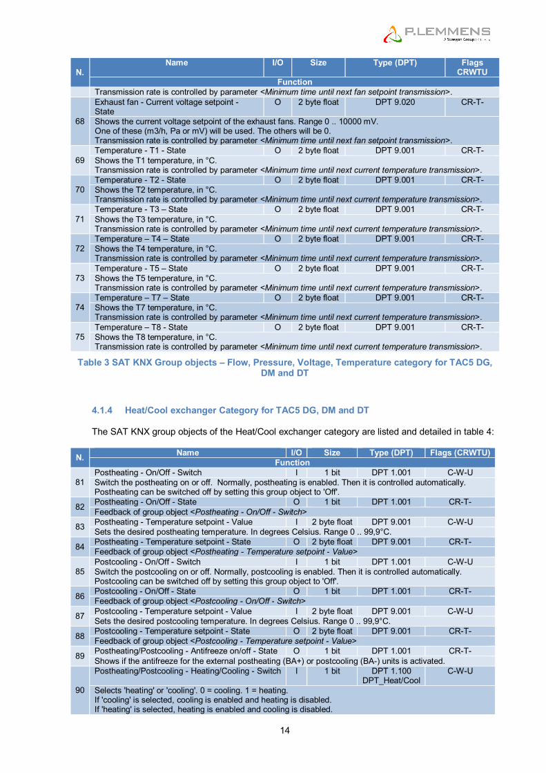
4.1.3 Flow, Pressure, Voltage, Temperature Category for TAC5 DG, DM and DT The SAT KNX group objects of the Flow, Pressure, Voltage, Temperature category are listed and
detailed in table 3:
N. Name I/O Size Type (DPT) Flags
CRWTU Function
51 Airflow - Ratio exhaust/supply flow – Value I 1 byte DPT 5.004
DPT_Percent_U8 C-W-U
Set the desired exhaust flow / supply flow ratio. Range 5..255%. (DPT 5.004: Value 0..255 means 0..255%)
52
Airflow - Ratio exhaust/supply flow – State O 1 byte DPT 5.004 DPT_Percent_U8
CR-T-
Shows the configured exhaust flow / supply flow ratio. Range 5..255%. If the ratio is configured > 255% it will be reported as 255% in KNX.
53
Airflow - Sleep mode - Value I 1 byte DPT 5.001 DPT_Scaling
C-W-U
Set the desired sleep mode airflow reduction percentage. Range 10..100%. (this value is internally stored with 1% resolution) (DPT 5.001: Value 0..255 means 0..100%)
54 Airflow - Sleep mode - State O 1 byte DPT 5.001
DPT_Scaling CR-T-
Shows the configured sleep mode airflow reduction percentage. Range 10..100%.
55 Fan 1 - Current airflow - State O 2 byte float DPT 9.009 CR-T- Shows the current airflow of fan 1. Range 0..19999 m3/h. Transmission rate is controlled by parameter <Minimum time until next current airflow or air pressure transmission>.
56 Fan 1 - Current airpressure - State O 2 byte float DPT 9.006 CR-T- Shows the current airpressure on fan 1. Range 0..11999 Pa. Transmission rate is controlled by parameter <Minimum time until next current airflow/airpressure/torque transmission>.
57 Fan 2 - Current airflow - State O 2 byte float DPT 9.009 CR-T- Shows the current airflow of fan 2. Range 0..19999 m3/h. Transmission rate is controlled by parameter <Minimum time until next current airflow/airpressure/torque transmission>.
58 Fan 2 - Current airpressure - State O 2 byte float DPT 9.006 CR-T- Shows the current airpressure on fan 2. Range 0..1999 Pa. Transmission rate is controlled by parameter <Minimum time until next current airflow/airpressure/torque transmission>.
59 Fan 3 - Current airflow - State O 2 byte float DPT 9.009 CR-T- Shows the current airflow of fan 3. Range 0..19999 m3/h. Transmission rate is controlled by parameter <Minimum time until next current airflow/airpressure/torque transmission>.
60 Fan 3 - Current airpressure - State O 2 byte float DPT 9.006 CR-T- Shows the current airpressure on fan 3. Range 0..1999 Pa. Transmission rate is controlled by parameter <Minimum time until next current airflow/airpressure/torque transmission>.
61 Fan 4 - Current airflow - State O 2 byte float DPT 9.009 CR-T- Shows the current airflow of fan 4. Range 0..19999 m3/h. Transmission rate is controlled by parameter <Minimum time until next current airflow/airpressure/torque transmission>.
62 Fan 4 - Current airpressure - State O 2 byte float DPT 9.006 CR-T- Shows the current airpressure on fan 4. Range 0..1999 Pa. Transmission rate is controlled by parameter <Minimum time until next current airflow/airpressure/torque transmission>.
63
Supply fan - Current flow setpoint - State O 2 byte float DPT 9.009 CR-T- Shows the current flow setpoint of the supply fans. Range 0 .. 19999 m3/h. One of these (m3/h, Pa or mV) will be used. The others will be 0. Transmission rate is controlled by parameter <Minimum time until next fan setpoint transmission>.
64
Supply fan - Current pressure setpoint - State
O 2 byte float DPT 9.006 CR-T-
Shows the current pressure setpoint of the supply fans. Range 0 .. 1999 Pa. One of these (m3/h, Pa or mV) will be used. The others will be 0. Transmission rate is controlled by parameter <Minimum time until next fan setpoint transmission>.
65
Supply fan - Current voltage setpoint - State O 2 byte float DPT 9.020 CR-T- Shows the current voltage setpoint of the supply fans. Range 0 .. 10000 mV. One of these (m3/h, Pa or mV) will be used. The others will be 0. Transmission rate is controlled by parameter <Minimum time until next fan setpoint transmission>.
66
Exhaust fan - Current flow setpoint - State O 2 byte float DPT 9.009 CR-T- Shows the current flow setpoint of the exhaust fans. Range 0 .. 19999 m3/h. One of these (m3/h, Pa or mV) will be used. The others will be 0. Transmission rate is controlled by parameter <Minimum time until next fan setpoint transmission>.
67
Exhaust fan - Current pressure setpoint - State
O 2 byte float DPT 9.006 CR-T-
Shows the current pressure setpoint of the exhaust fans. Range 0 .. 1999 Pa. One of these (m3/h, Pa or mV) will be used. The others will be 0.
14
N. Name I/O Size Type (DPT) Flags
CRWTU Function
Transmission rate is controlled by parameter <Minimum time until next fan setpoint transmission>.
68
Exhaust fan - Current voltage setpoint - State
O 2 byte float DPT 9.020 CR-T-
Shows the current voltage setpoint of the exhaust fans. Range 0 .. 10000 mV. One of these (m3/h, Pa or mV) will be used. The others will be 0. Transmission rate is controlled by parameter <Minimum time until next fan setpoint transmission>.
69 Temperature - T1 - State O 2 byte float DPT 9.001 CR-T- Shows the T1 temperature, in °C. Transmission rate is controlled by parameter <Minimum time until next current temperature transmission>.
70 Temperature - T2 - State O 2 byte float DPT 9.001 CR-T- Shows the T2 temperature, in °C. Transmission rate is controlled by parameter <Minimum time until next current temperature transmission>.
71 Temperature - T3 – State O 2 byte float DPT 9.001 CR-T- Shows the T3 temperature, in °C. Transmission rate is controlled by parameter <Minimum time until next current temperature transmission>.
72 Temperature – T4 – State O 2 byte float DPT 9.001 CR-T- Shows the T4 temperature, in °C. Transmission rate is controlled by parameter <Minimum time until next current temperature transmission>.
73 Temperature - T5 – State O 2 byte float DPT 9.001 CR-T- Shows the T5 temperature, in °C. Transmission rate is controlled by parameter <Minimum time until next current temperature transmission>.
74 Temperature – T7 – State O 2 byte float DPT 9.001 CR-T- Shows the T7 temperature, in °C. Transmission rate is controlled by parameter <Minimum time until next current temperature transmission>.
75 Temperature – T8 - State O 2 byte float DPT 9.001 CR-T- Shows the T8 temperature, in °C. Transmission rate is controlled by parameter <Minimum time until next current temperature transmission>.
Table 3 SAT KNX Group objects – Flow, Pressure, Voltage, Temperature category for TAC5 DG, DM and DT
4.1.4 Heat/Cool exchanger Category for TAC5 DG, DM and DT The SAT KNX group objects of the Heat/Cool exchanger category are listed and detailed in table 4:
N. Name I/O Size Type (DPT) Flags (CRWTU) Function
81 Postheating - On/Off - Switch I 1 bit DPT 1.001 C-W-U Switch the postheating on or off. Normally, postheating is enabled. Then it is controlled automatically. Postheating can be switched off by setting this group object to 'Off'.
82 Postheating - On/Off - State O 1 bit DPT 1.001 CR-T- Feedback of group object <Postheating - On/Off - Switch>
83 Postheating - Temperature setpoint - Value I 2 byte float DPT 9.001 C-W-U Sets the desired postheating temperature. In degrees Celsius. Range 0 .. 99,9°C.
84 Postheating - Temperature setpoint - State O 2 byte float DPT 9.001 CR-T- Feedback of group object <Postheating - Temperature setpoint - Value>
85 Postcooling - On/Off - Switch I 1 bit DPT 1.001 C-W-U Switch the postcooling on or off. Normally, postcooling is enabled. Then it is controlled automatically. Postcooling can be switched off by setting this group object to 'Off'.
86 Postcooling - On/Off - State O 1 bit DPT 1.001 CR-T- Feedback of group object <Postcooling - On/Off - Switch>
87 Postcooling - Temperature setpoint - Value I 2 byte float DPT 9.001 C-W-U Sets the desired postcooling temperature. In degrees Celsius. Range 0 .. 99,9°C.
88 Postcooling - Temperature setpoint - State O 2 byte float DPT 9.001 CR-T- Feedback of group object <Postcooling - Temperature setpoint - Value>
89 Postheating/Postcooling - Antifreeze on/off - State O 1 bit DPT 1.001 CR-T- Shows if the antifreeze for the external postheating (BA+) or postcooling (BA-) units is activated.
90
Postheating/Postcooling - Heating/Cooling - Switch I 1 bit DPT 1.100 DPT_Heat/Cool
C-W-U
Selects 'heating' or 'cooling'. 0 = cooling. 1 = heating. If 'cooling' is selected, cooling is enabled and heating is disabled. If 'heating' is selected, heating is enabled and cooling is disabled.

Installation and user’s manual TAC5 + KNX
15
N. Name I/O Size Type (DPT) Flags (CRWTU) Function
91 Postheating/Postcooling- Heating/Cooling - State O 1 bit DPT 1.100
DPT_Heat/Cool CR-T-
Shows if heating or cooling is selected. 0 = cooling. 1 = heating.
92 Postheating/Postcooling - On/Off - State O 1 bit DPT 1.001 CR-T- Shows if heating or cooling is on.
93 Postheating/Postcooling - Current setpoint - State O 2 byte float DPT 9.001 CR-T- Shows the current setpoint for heating/cooling setpoint temperature. Range 0 .. 99.9 °C.
94 Heat exchanger - Antifreeze on/off - State O 1 bit DPT 1.001 CR-T- Shows if the antifreeze for the internal heat exchanger or NV is activated.
95 Freecooling - Temperature setpoint - Value I 2 byte float DPT 9.001 C-W-U Sets the desired freecooling temperature. In degrees Celsius. Range 0 .. 99,9°C.
96 Freecooling - Temperature setpoint – State O 2 byte float DPT 9.001 CR-T- Feedback of group object <Freecooling - Temperature setpoint - Value>
Table 4 SAT KNX Group objects – Heat/Cool exchanger category for TAC5 DG, DM and DT
4.1.5 Alarms Category for TAC5 DG, DM and DT The SAT KNX group objects of the Alarms category are listed and detailed in table 5:
N. Name I/O Size Type (DPT) Flags
CRWTU Function
101 Alarm - Pressure - Trigger I 1 bit DPT 1.005 C-W-U Force a pressure alarm. Intended for external overpressure detector. 0 = no alarm. 1 = alarm.
102 Alarm - Fire - Trigger I 1 bit DPT 1.005 C-W-U Set the fire alarm on. Intended for external fire alarm I. 0 = no alarm. 1 = alarm.
103 Alarm - State O 1 bit DPT 1.005 CR-T- Shows that an alarm (non-fatal or fatal) is pending. 0 = no alarm, 1 = alarm. Alarm number is in group object <Alarm - Number - State> Is always sent on start up.
104 Alarm - Fatal - State O 1 bit DPT 1.005 CR-T- Shows that a fatal alarm is pending. Ventilation is stopped. 0 = no alarm, 1 = alarm. Alarm number is in group object <Alarm - Number - State> Is always sent on start up.
105
Alarm - Number - State O 1 byte DPT 5 CR-T- Value that shows the pending alarm. This is an enumeration. Each value represents a certain alarm. 0 = No alarm 1 = Software alarm: The program code in flash has a checksum error, or the configuration data in eeprom has a checksum error. Fatal. 2 = Fan alarm: a fan is defective. Fatal. 3 = Pressure alarm: overpressure. 4 = T° sensor alarm: a temperature sensor is defective. Fatal. 5 = Setpoint alarm: can’t reach the requested setpoint. 6 = Service warning alarm. 7 = Stop-for-service alarm. Fatal. 8 = Fire Alarm. Fatal. 9 = Antifrost alarm: in antifreeze mode. 10 = Condensate drain pan is full. 11 = Comfort temperature alarm (postheating, postcooling) 12 = Heatwheel speed. Fatal. 13 = Modulating bypass position alarm. Fatal. 14 = SAT-BA module does not respond. Fatal. 15-255: reserved. Is always sent on start up.
Table 5 SAT KNX Group objects – Alarms category for TAC5 DG, DM and DT

16
4.1.6 Analogue Input/Output Category for TAC5 DG, DM and DT
The SAT KNX group objects of the Analogue Input/Output category are listed and detailed in table 6:
N. Name I/O Size Type (DPT) Flags
CRWTU Function
111
Analog input - K2 – State O 1 byte DPT 5.001 DPT_Scaling
CR-T-
Shows the actual level on analogue input K2. Range 0..100%. (DPT 5.001: Value 0..255 means 0..100%). Transmission rate is controlled by parameter <Minimum time until next input status transmission>.
112
Analog input - K3 – State O 1 byte DPT 5.001 DPT_Scaling
CR-T-
Shows the actual level on analogue input K3. Range 0..100%. (DPT 5.001: Value 0..255 means 0..100%). Transmission rate is controlled by parameter <Minimum time until next input status transmission>.
113
Analog output - OUT1 - State O 1 byte DPT 5.001 DPT_Scaling
CR-T-
Shows the actual level on analogue output OUT1. In %. (DPT 5.001: Value 0..255 means 0..100%). Transmission rate is controlled by parameter <Minimum time until next output status transmission>.
114
Analog output - OUT4 - State O 1 byte DPT 5.001 DPT_Scaling
CR-T-
Shows the actual level on analogue output OUT4. In %. (DPT 5.001: Value 0..255 means 0..100%). Transmission rate is controlled by parameter <Minimum time until next output status transmission>.
115
Analog output - OUT7 - State O 1 byte DPT 5.001 DPT_Scaling
CR-T-
Shows the actual level on analogue output OUT7. In %. (DPT 5.001: Value 0..255 means 0..100%). Transmission rate is controlled by parameter <Minimum time until next output status transmission>.
116
Analog output - OUT8 - State O 1 byte DPT 5.001 DPT_Scaling
CR-T-
Shows the actual level on analogue output OUT8. In %. (DPT 5.001: Value 0..255 means 0..100%). Transmission rate is controlled by parameter <Minimum time until next output status transmission>.
117
Analog output - KWin - State O 1 byte DPT 5.001 DPT_Scaling
CR-T-
Shows the actual level on analogue output KWin. In %. (DPT 5.001: Value 0..255 means 0..100%). Transmission rate is controlled by parameter <Minimum time until next output status transmission>.
118
Analog output - KWout - State O 1 byte DPT 5.001 DPT_Scaling
CR-T-
Shows the actual level on analogue output KWout. In %. (DPT 5.001: Value 0..255 means 0..100%). Transmission rate is controlled by parameter <Minimum time until next output status transmission>.
119
Analog output - KWext - State O 1 byte DPT 5.001 DPT_Scaling
CR-T-
Shows the actual level on analogue output KWext. In %. (DPT 5.001: Value 0..255 means 0..100%). Transmission rate is controlled by parameter <Minimum time until next output status transmission>.
120
Bypass% - Position - State O 1 byte DPT 5.001 DPT_Scaling
CR-T-
Shows the position of the proportional bypass valve. 0% means closed, 100% means fully open. (DPT 5.001: Value 0..255 means 0..100%). Transmission rate is controlled by parameter <Minimum time until next output status transmission>.
Table 6 SAT KNX Group objects – Analogue Input/Output category for TAC5 DG, DM and DT
Installation and user’s manual TAC5 + KNX
17
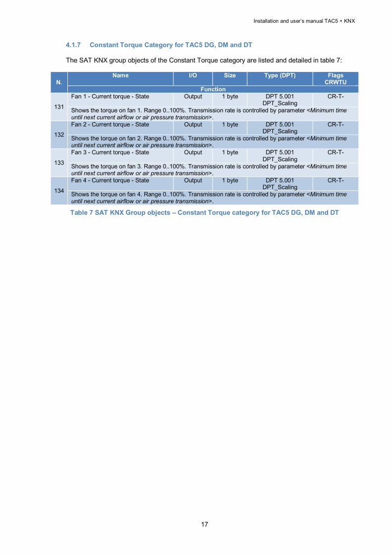
4.1.7 Constant Torque Category for TAC5 DG, DM and DT The SAT KNX group objects of the Constant Torque category are listed and detailed in table 7:
N. Name I/O Size Type (DPT) Flags
CRWTU Function
131
Fan 1 - Current torque - State Output 1 byte DPT 5.001 DPT_Scaling
CR-T-
Shows the torque on fan 1. Range 0..100%. Transmission rate is controlled by parameter <Minimum time until next current airflow or air pressure transmission>.
132
Fan 2 - Current torque - State Output 1 byte DPT 5.001 DPT_Scaling
CR-T-
Shows the torque on fan 2. Range 0..100%. Transmission rate is controlled by parameter <Minimum time until next current airflow or air pressure transmission>.
133
Fan 3 - Current torque - State Output 1 byte DPT 5.001 DPT_Scaling
CR-T-
Shows the torque on fan 3. Range 0..100%. Transmission rate is controlled by parameter <Minimum time until next current airflow or air pressure transmission>.
134
Fan 4 - Current torque - State Output 1 byte DPT 5.001 DPT_Scaling
CR-T-
Shows the torque on fan 4. Range 0..100%. Transmission rate is controlled by parameter <Minimum time until next current airflow or air pressure transmission>.
Table 7 SAT KNX Group objects – Constant Torque category for TAC5 DG, DM and DT

18
4.2 Group objects categories for TAC5 SC, F The categories are presented with the hypothesis that two fans are presents. If only one fan is present, only the objects referred to “fan 1” should be considered.
4.2.1 Drive Category for TAC5 SC, F The SAT KNX group objects of the drive category are listed and detailed in table 8:
N. Name I/O Size Type (DPT) Flags
CRWTU Function
1
Pilot - Main switch – Switch I 1 bit DPT 1.001 C-W-U Turn fans on or off. If turned on and group object <Airflow – Fan 1 flow - Value> or <Airflow – Fan 2 flow - Value> is set to a value > 0, then the fans are started in 'constant airflow' mode. If turned on and group objects <Airflow – Fan 1 flow - Value> and <Airflow – Fan 2 flow - Value> are set to 0, then the fans are started in the mode that is configured. The intention is to control the HVAC using one of the following group objects: use <Pilot - Main switch - Switch> or <Pilot - Fan speed 1 on/off - Switch>.<Pilot - Fan speed 3 on/off - Switch> or <Pilot - Speed % - Value> or <Pilot - Set Fan 1 flow % - Value> and <Pilot - Set Fan 2 flow % - Value> (using a mix might get confusing)
2 Pilot - Main switch – State O 1 bit DPT 1.001 CR-T- Shows if HVAC unit is currently On or Off. 'On' means fans running. Is always sent on start up.
3 Pilot - Fan speed 1 on/off - Switch I 1 bit DPT 1.001 C-W-U Select fans speed 1. Writing value 1 activates speed 1 and resets the other <Pilot - Fan speed * on/off - Switch> group objects. Writing 0 stops fans.
4 Pilot - Fan speed 2 on/off - Switch I 1 bit DPT 1.001 C-W-U Select fans speed 2. Writing value 1 activates speed 2 and resets the other <Pilot - Fan speed * on/off - Switch> group objects. Writing 0 stops fans.
5 Pilot - Fan speed 3 on/off - Switch I 1 bit DPT 1.001 C-W-U Select fans speed 3. Writing value 1 activates speed 3 and resets the other <Pilot - Fan speed * on/off - Switch> group objects. Writing 0 stops fans.
6 Pilot - Fan speed 1 on/off - State O 1 bit DPT 1.001 CR-T- Is 'On' if fans are running with speed 1 (LOW speed)
7 Pilot - Fan speed 2 on/off - State O 1 bit DPT 1.001 CR-T- Is 'On' if fans are running with speed 2 (MEDIUM speed)
8 Pilot - Fan speed 3 on/off - State O 1 bit DPT 1.001 CR-T- Is 'On' if fans are running with speed 3 (HIGH speed)
9
Pilot - Speed % - Value I 1 byte DPT 5.001 DPT_Scaling
C-W-U
Select fans speed with a percentage value. 0 - 9%: Fans OFF 40 - 69%: MEDIUM speed 10 - 39%: LOW speed 70 - 100%: HIGH speed
10
Pilot - Speed % - State O 1 byte DPT 5.001 DPT_Scaling
CR-T-
Shows the current fans speed as a percentage: 0% if fans are OFF, 33% for LOW speed, 66% for MEDIUM speed, 100% for HIGH speed.
11
Pilot - Set Fan 1 flow % - Value I 1 byte DPT 5.001 DPT_Scaling
C-W-U
Set fan 1 flow as 0..100% of the fan's max flow. This overrides the normal control via the viewer OFF/I/II/III buttons. If set: forces 'constant airflow' mode with independent airflow setpoints for fans 1 and 2. If group object <Airflow – Fan 1 flow - Value> or <Airflow – Fan 2 flow - Value> is changed and either is set to a value > 0, then the 'constant airflow' mode is activated and the fans are started. If group object <Airflow – Fan 1 flow - Value> or <Airflow – Fan 2 flow - Value> is changed and both are set to 0, then the 'constant airflow' mode is terminated and the fans are stopped. Normal control via the viewer is resumed. (DPT 5.001: Value 0..255 means 0..100%).
12 Pilot - Set Fan 1 flow % - State O 1 byte DPT 5.001
DPT_Scaling CR-T-
Feedback of group object <Airflow – Fan 1 flow - Value>
13 Pilot - Set Fan 2 flow % - Value I 1 byte DPT 5.001 DPT_Scaling
C-W-U

Installation and user’s manual TAC5 + KNX
19
N. Name I/O Size Type (DPT) Flags
CRWTU Function
Set fan 2 flow as 0..100% of the fan's max flow. This overrides the normal control via the viewer OFF/I/II/III buttons. If set: forces 'constant airflow' mode with independent airflow setpoints for fans 1 and 2. If group object <Airflow – Fan 1 flow - Value> or <Airflow – Fan 2 flow - Value> is changed and either is set to a value > 0, then the 'constant airflow' mode is activated and the fans are started. If group object <Airflow – Fan 1 flow - Value> or <Airflow – Fan 2 flow - Value> is changed and both are set to 0, then the 'constant airflow' mode is terminated and the fans are stopped. Normal control via the viewer is resumed. (DPT 5.001: Value 0..255 means 0..100%).
14 Pilot - Set Fan 2 flow % - State O 1 byte DPT 5.001
DPT_Scaling CR-T-
Feedback of group object <Airflow – Fan 2 flow - Value>
15 Pilot - Fans Running - State O 1 bit DPT 1.002 CR-T- Shows that all fans (that should be running) are running. Is 1 (True) if fans are running. Is always sent on start up.
16
Pilot - Working hours - State O 2 byte unsigned
DPT 7.007 CR-T-
Shows the number of working hours of the fans. 0 .. 65535 hours. If the number of working hours internally is over 65535 hours, it will be reported as 65535 hours in KNX.
17 Pilot - Reset working hours - Trigger I 1 bit DPT 1.015
DPT_Reset C-W-U
Reset Fans working hours to zero 0 = no action. 1 = reset. Is turned off automatically.
18
Pilot - Reset pending alarms - Trigger I 1 bit DPT 1.015 DPT_Reset
C-W-U
Perform a RESET to clear pending alarms and resume normal working. 0 = no action. 1 = reset. Is turned off automatically.
19
Pilot - Working mode - State O 1 byte DPT 5 CR-T- Value that shows the current working mode. This is an enumeration. Each value represents a certain working mode. 0 = Off (OFF) 1 = Constant airflow mode (CA) 2 = Linked system mode (LS) 3 = Constant air pressure mode (CPf)
4 = Constant air pressure mode with sensor (CPs) 5 = Initializing (INIT) 6 = Constant Torque mode (TQ) 7-255: reserved
Table 8 SAT KNX Group objects – Drive category for TAC5 SC, F
4.2.2 Mode and functions Category for TAC5 SC, F The SAT KNX group objects of the Mode and functions category are listed and detailed in table 9:
N. Name I/O Size Type (DPT) Flags
CRWTU Function
31 CPs mode – Fan 1 setpoint - Value I 2 byte float DPT 9.020 C-W-U Set voltage setpoint for CPs mode for fan 1. Range 0 .. 10000 mV. (voltage is internally stored with 0.1V resolution)
32 CPs mode – Fan 1 setpoint – State O 2 byte float DPT 9.020 CR-T- Feedback of group object <CPs mode – Fan 1 setpoint - Value>
33 CPs mode – Fan 2 setpoint – Value [TAC5 F] I 2 byte float DPT 9.020 C-W-U Set voltage setpoint for CPs mode for fan 2. Range 0 .. 10000 mV. (voltage is internally stored with 0.1V resolution)
34 CPs mode – Fan 2 setpoint – State [TAC5 F] O 2 byte float DPT 9.020 CR-T- Feedback of group object <CPs mode – Fan 2 setpoint - Value>
35 CPf mode – Fan 1 setpoint - Value I 2 byte float DPT 9.006 C-W-U Set the pressure setpoint for CPf mode for Fan 1. Range 0 .. 1999 Pa. (pressure is internally stored with 1Pa resolution)
36 CPf mode – Fan 1 setpoint – State O 2 byte float DPT 9.006 CR-T- Feedback of group object <CPf mode – Fan 1 setpoint - Value>
37 CPf mode – Fan 2 setpoint – Value [TAC5 F] I 2 byte float DPT 9.006 C-W-U Set the pressure setpoint for CPf mode for fan 2. Range 0 .. 1999 Pa. (pressure is internally stored with 1Pa resolution)
38 CPf mode – Fan 2 setpoint – State [TAC5 F] O 2 byte float DPT 9.006 CR-T- Feedback of group object <CPf mode – Fan 2 setpoint - Value>

20
N. Name I/O Size Type (DPT) Flags
CRWTU Function
39 Operation mode - Automatic on/off - Switch I 1 bit DPT 1.001 C-W-U Turn 'automatic' mode on or off. In automatic mode, the HVAC is controlled using a timetable. Automatic mode can only be used if a timetable is configured.
40 Operation mode - Automatic on/off – State O 1 bit DPT 1.001 CR-T- Shows if 'automatic' mode is on
41 Operation mode - Boost on/off - Switch I 1 bit DPT 1.001 C-W-U Force boost mode on (high air flow).
42 Operation mode - Boost on/off – State O 1 bit DPT 1.001 CR-T- Shows if boost mode is on
46
Air inlet function - Valve open/close - State O 1 bit DPT 1.009 CR-T- Shows the status of the air inlet valve (CT-in option). (0=open, 1=closed) While the valve is opening, the status is reported as 'open'. While the valve is closing, the status is reported as 'closed'.
47 MK3 function - MK3 on/off – Switch [TAC5 SC] I 1 bit DPT 1.001 C-W-U Force activation of MK3 (mixing cabinet). When this group object is set to 'on' the MK3 function is forced active.
48
MK3 function - Current Status – State [TAC5 SC] O 1 bit DPT 1.001 CR-T- Shows if the MK3 function is on. During the switchover from off to on, the status is reported as 'on'. During the switchover from on to off, the status is reported as 'off'.
Table 9 SAT KNX Group objects – Mode and Function category for TAC5 SC, F
4.2.3 Flow, Pressure, Voltage Category for TAC5 SC, F
The SAT KNX group objects of the Flow, Pressure, Voltage, Temperature category are listed and detailed in table 10:
N. Name I/O Size Type (DPT) Flags
CRWTU Function
51
Airflow - Ratio fan 2/fan 1 flow – Value I 1 byte DPT 5.004 DPT_Percent_U8
C-W-U
Set the desired fan 2 flow / fan 1 flow ratio. In configuration with 2 dependents fans. Range 5..255%. (DPT 5.004: Value 0..255 means 0..255%)
52
Airflow - Ratio fan 2/fan 1 flow – State O 1 byte DPT 5.004 DPT_Percent_U8
CR-T-
Shows the configured fan 2 flow / fan 1 flow ratio. In configuration with 2 dependents fans. Range 5..255%. If the ratio is configured > 255% it will be reported as 255% in KNX.
53
Airflow - Sleep mode - Value I 1 byte DPT 5.001 DPT_Scaling
C-W-U
Set the desired sleep mode airflow reduction percentage. Range 10..100%. (this value is internally stored with 1% resolution) (DPT 5.001: Value 0..255 means 0..100%)
54 Airflow - Sleep mode - State O 1 byte DPT 5.001
DPT_Scaling CR-T-
Shows the configured sleep mode airflow reduction percentage. Range 10..100%.
55 Fan 1 - Current airflow - State O 2 byte float DPT 9.009 CR-T- Shows the current airflow of fan 1. Range 0..19999 m3/h. Transmission rate is controlled by parameter <Minimum time until next current airflow or air pressure transmission>.
56 Fan 1 - Current airpressure - State O 2 byte float DPT 9.006 CR-T- Shows the current airpressure on fan 1. Range 0..11999 Pa. Transmission rate is controlled by parameter <Minimum time until next current airflow/airpressure/torque transmission>.
59 Fan 2 - Current airflow – State O 2 byte float DPT 9.009 CR-T- Shows the current airflow of fan 2. Range 0..19999 m3/h. Transmission rate is controlled by parameter <Minimum time until next current airflow/airpressure/torque transmission>.
60 Fan 2 - Current airpressure - State O 2 byte float DPT 9.006 CR-T- Shows the current airpressure on fan 2. Range 0..1999 Pa. Transmission rate is controlled by parameter <Minimum time until next current airflow/airpressure/torque transmission>.
63 Fan 1 - Current flow setpoint - State O 2 byte float DPT 9.009 CR-T- Shows the current flow setpoint of fan 1. Range 0 .. 19999 m3/h. One of these (m3/h, Pa or mV) will be used. The others will be 0.

Installation and user’s manual TAC5 + KNX
21
70 Temperature - T2 – State [TAC5 SC] O 2 byte float DPT 9.001 CR-T- Shows the T2 temperature, in °C. Transmission rate is controlled by parameter <Minimum time until next current temperature transmission>.
73 Temperature - T5 – State [TAC5 SC] O 2 byte float DPT 9.001 CR-T- Shows the T5 temperature, in °C. Transmission rate is controlled by parameter <Minimum time until next current temperature transmission>.
74 Temperature – T7 – State [TAC5 SC] O 2 byte float DPT 9.001 CR-T- Shows the T7 temperature, in °C. Transmission rate is controlled by parameter <Minimum time until next current temperature transmission>.
75 Temperature – T8 – State [TAC5 SC] O 2 byte float DPT 9.001 CR-T- Shows the T8 temperature, in °C. Transmission rate is controlled by parameter <Minimum time until next current temperature transmission>.
Table 10 SAT KNX Group objects – Flow, Pressure, Voltage category for TAC5 SC, F
4.2.4 Heat/Cool exchanger Category for TAC5 SC The SAT KNX group objects of the Heat/Cool exchanger category are listed and detailed in table
11:
N. Name I/O Size Type (DPT) Flags (CRWTU) Function
81 Postheating - On/Off - Switch I 1 bit DPT 1.001 C-W-U Switch the postheating on or off. Normally, postheating is enabled. Then it is controlled automatically. Postheating can be switched off by setting this group object to 'Off'.
82 Postheating - On/Off - State O 1 bit DPT 1.001 CR-T- Feedback of group object <Postheating - On/Off - Switch>
83 Postheating - Temperature setpoint - Value I 2 byte float DPT 9.001 C-W-U Sets the desired postheating temperature. In degrees Celsius. Range 0 .. 99,9°C.
84 Postheating - Temperature setpoint - State O 2 byte float DPT 9.001 CR-T- Feedback of group object <Postheating - Temperature setpoint - Value>
85 Postcooling - On/Off - Switch I 1 bit DPT 1.001 C-W-U Switch the postcooling on or off. Normally, postcooling is enabled. Then it is controlled automatically. Postcooling can be switched off by setting this group object to 'Off'.
86 Postcooling - On/Off - State O 1 bit DPT 1.001 CR-T- Feedback of group object <Postcooling - On/Off - Switch>
87 Postcooling - Temperature setpoint - Value I 2 byte float DPT 9.001 C-W-U Sets the desired postcooling temperature. In degrees Celsius. Range 0 .. 99,9°C.
Transmission rate is controlled by parameter <Minimum time until next fan setpoint transmission>.
64
Fan 1 - Current pressure setpoint - State O 2 byte float DPT 9.006 CR-T- Shows the current pressure setpoint of fan 1. Range 0 .. 1999 Pa. One of these (m3/h, Pa or mV) will be used. The others will be 0. Transmission rate is controlled by parameter <Minimum time until next fan setpoint transmission>.
65
Fan 1 - Current voltage setpoint - State O 2 byte float DPT 9.020 CR-T- Shows the current voltage setpoint of fan 1. Range 0 .. 10000 mV. One of these (m3/h, Pa or mV) will be used. The others will be 0. Transmission rate is controlled by parameter <Minimum time until next fan setpoint transmission>.
66
Fan 2 - Current flow setpoint - State O 2 byte float DPT 9.009 CR-T- Shows the current flow setpoint of fan 2. Range 0 .. 19999 m3/h. One of these (m3/h, Pa or mV) will be used. The others will be 0. Transmission rate is controlled by parameter <Minimum time until next fan setpoint transmission>.
67
Fan 2 - Current pressure setpoint – State [TAC5 F]
O 2 byte float DPT 9.006 CR-T-
Shows the current pressure setpoint of fan 2. Range 0 .. 1999 Pa. One of these (m3/h, Pa or mV) will be used. The others will be 0. Transmission rate is controlled by parameter <Minimum time until next fan setpoint transmission>.
68
Fan 2 - Current voltage setpoint – State [TAC5 F]
O 2 byte float DPT 9.020 CR-T-
Shows the current voltage setpoint of fan 2. Range 0 .. 10000 mV. One of these (m3/h, Pa or mV) will be used. The others will be 0. Transmission rate is controlled by parameter <Minimum time until next fan setpoint transmission>.

22
N. Name I/O Size Type (DPT) Flags (CRWTU) Function
88 Postcooling - Temperature setpoint - State O 2 byte float DPT 9.001 CR-T- Feedback of group object <Postcooling - Temperature setpoint - Value>
89 Postheating/Postcooling - Antifreeze on/off - State O 1 bit DPT 1.001 CR-T- Shows if the antifreeze for the external postheating (BA+) or postcooling (BA-) units is activated.
90
Postheating/Postcooling - Heating/Cooling - Switch I 1 bit DPT 1.100 DPT_Heat/Cool
C-W-U
Selects 'heating' or 'cooling'. 0 = cooling. 1 = heating. If 'cooling' is selected, cooling is enabled and heating is disabled. If 'heating' is selected, heating is enabled and cooling is disabled.
91 Postheating/Postcooling- Heating/Cooling - State O 1 bit DPT 1.100
DPT_Heat/Cool CR-T-
Shows if heating or cooling is selected. 0 = cooling. 1 = heating.
92 Postheating/Postcooling - On/Off - State O 1 bit DPT 1.001 CR-T- Shows if heating or cooling is on.
93 Postheating/Postcooling - Current setpoint - State O 2 byte float DPT 9.001 CR-T- Shows the current setpoint for heating/cooling setpoint temperature. Range 0 .. 99.9 °C.
Table 11 SAT KNX Group objects – Heat/Cool exchanger category for TAC5 SC
4.2.5 Alarms Category for TAC5 SC, F The SAT KNX group objects of the Alarms category are listed and detailed in table 12:
N. Name I/O Size Type (DPT) Flags
CRWTU Function
101 Alarm - Pressure - Trigger I 1 bit DPT 1.005 C-W-U Force a pressure alarm. Intended for external overpressure detector. 0 = no alarm. 1 = alarm.
102 Alarm - Fire - Trigger I 1 bit DPT 1.005 C-W-U Set the fire alarm on. Intended for external fire alarm I. 0 = no alarm. 1 = alarm.
103 Alarm - State O 1 bit DPT 1.005 CR-T- Shows that an alarm (non-fatal or fatal) is pending. 0 = no alarm, 1 = alarm. Alarm number is in group object <Alarm - Number - State> Is always sent on start up.
104 Alarm - Fatal - State O 1 bit DPT 1.005 CR-T- Shows that a fatal alarm is pending. Ventilation is stopped. 0 = no alarm, 1 = alarm. Alarm number is in group object <Alarm - Number - State> Is always sent on start up.
105
Alarm - Number - State O 1 byte DPT 5 CR-T- Value that shows the pending alarm. This is an enumeration. Each value represents a certain alarm. 0 = No alarm 1 = Software alarm: The program code in flash has a checksum error, or the configuration data in eeprom has a checksum error. Fatal. 2 = Fan alarm: a fan is defective. Fatal. 3 = Pressure alarm: overpressure. 4 = Not used. 5 = Setpoint alarm: can’t reach the requested setpoint. 6 = Service warning alarm. 7 = Stop-for-service alarm. Fatal. 8 = Fire Alarm. Fatal. 9 = Not used. 10 = Not used. 11 = Comfort temperature alarm (postheating, postcooling) [TAC5 SC] 12 = Not used. 13 = Not used. 14 = SAT-BA module does not respond. Fatal. [TAC5 SC]. 15-255: reserved. Is always sent on start up.
Table 12 SAT KNX Group objects – Alarms category for TAC5 SC, F
Installation and user’s manual TAC5 + KNX
23
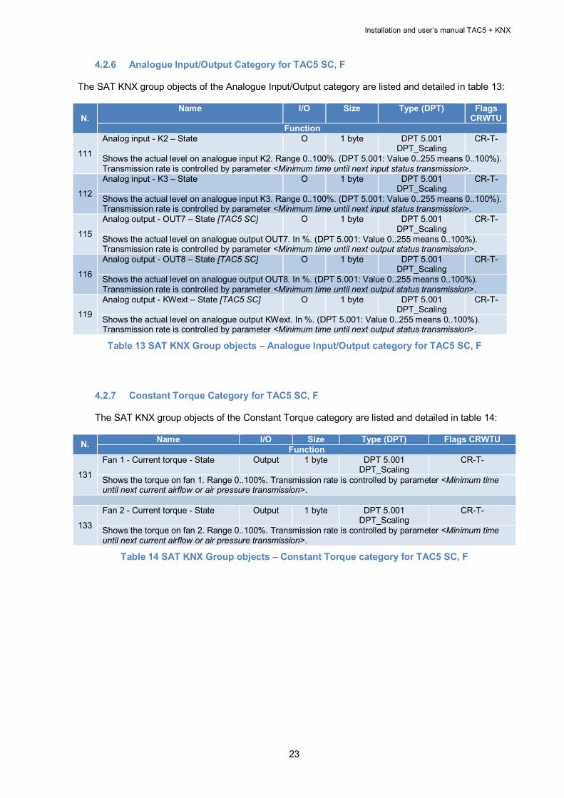
4.2.6 Analogue Input/Output Category for TAC5 SC, F
The SAT KNX group objects of the Analogue Input/Output category are listed and detailed in table 13:
N. Name I/O Size Type (DPT) Flags
CRWTU Function
111
Analog input - K2 – State O 1 byte DPT 5.001 DPT_Scaling
CR-T-
Shows the actual level on analogue input K2. Range 0..100%. (DPT 5.001: Value 0..255 means 0..100%). Transmission rate is controlled by parameter <Minimum time until next input status transmission>.
112
Analog input - K3 – State O 1 byte DPT 5.001 DPT_Scaling
CR-T-
Shows the actual level on analogue input K3. Range 0..100%. (DPT 5.001: Value 0..255 means 0..100%). Transmission rate is controlled by parameter <Minimum time until next input status transmission>.
115
Analog output - OUT7 – State [TAC5 SC] O 1 byte DPT 5.001 DPT_Scaling
CR-T-
Shows the actual level on analogue output OUT7. In %. (DPT 5.001: Value 0..255 means 0..100%). Transmission rate is controlled by parameter <Minimum time until next output status transmission>.
116
Analog output - OUT8 – State [TAC5 SC] O 1 byte DPT 5.001 DPT_Scaling
CR-T-
Shows the actual level on analogue output OUT8. In %. (DPT 5.001: Value 0..255 means 0..100%). Transmission rate is controlled by parameter <Minimum time until next output status transmission>.
119
Analog output - KWext – State [TAC5 SC] O 1 byte DPT 5.001 DPT_Scaling
CR-T-
Shows the actual level on analogue output KWext. In %. (DPT 5.001: Value 0..255 means 0..100%). Transmission rate is controlled by parameter <Minimum time until next output status transmission>.
Table 13 SAT KNX Group objects – Analogue Input/Output category for TAC5 SC, F
4.2.7 Constant Torque Category for TAC5 SC, F The SAT KNX group objects of the Constant Torque category are listed and detailed in table 14:
N. Name I/O Size Type (DPT) Flags CRWTU Function
131
Fan 1 - Current torque - State Output 1 byte DPT 5.001 DPT_Scaling
CR-T-
Shows the torque on fan 1. Range 0..100%. Transmission rate is controlled by parameter <Minimum time until next current airflow or air pressure transmission>.
133
Fan 2 - Current torque - State Output 1 byte DPT 5.001 DPT_Scaling
CR-T-
Shows the torque on fan 2. Range 0..100%. Transmission rate is controlled by parameter <Minimum time until next current airflow or air pressure transmission>.
Table 14 SAT KNX Group objects – Constant Torque category for TAC5 SC, F

24
4.3 Control and optimization parameters of the KNX bus These parameters are not group objects and enable to control and to optimize the use of the KNX
bus. They are listed in table 15:
N. Name Size /Type Default value Function
1 Delay before sending group objects (0 - 255 sec) Byte 2 Delay before any group object is transmitted to the KNX bus after start up. Group objects are sent only if they change value. Range 0 .. 255 seconds.
2
Maximum number of messages sent per second (1 - 255) Byte 10 To control KNX bus load. Limit the number of group objects transmitted per second. If the maximum number of messages sent per second is reached, further messages will be delayed until the next second. Range 1..255.
3 Minimum time until next fan setpoint transmission (0 - 255 sec) Byte 5 To control KNX bus load. Sometimes fan setpoint values may change frequently. This parameter defines a minimum delay time before the same group object is sent again. Range 0..255 seconds.
4
Minimum time until next current airflow/airpressure/torque transmission (0 - 255 sec)
Byte 5
To control KNX bus load. The fan's current airflow and airpressure will change frequently. This parameter defines a minimum delay time before the same group object is sent again. Range 0..255 seconds.
5 Minimum time until next input status transmission (0 - 255 sec) Byte 5 To control KNX bus load. Sometimes input values (mainly analogue inputs) may change frequently. This parameter defines a minimum delay time before the same group object is sent again. Range 0..255 seconds.
6 Minimum time until next current temperature transmission (0 - 255 sec) Byte 30 To control KNX bus load. Sometimes temperature inputs may change frequently. This parameter defines a minimum delay time before the same group object is sent again. Range 0..255 seconds.
7 Minimum time until next output state transmission (0 - 255 sec) Byte 5 To control KNX bus load. Sometimes output values 'mainly analogue outputs) may change frequently. This parameter defines a minimum delay time before the same group object is sent again. Range 0..255 seconds.
Table 15 Control and Optimization parameters of the KNX bus
5. INTEGRATION OF THE SAT KNX IN A ETS™ PROJECT (4 OR MAJOR) The integration of the SAT KNX presumes and requires from the user the necessary knowledge of ETS™ software, version 4 or major provided by the KNX organization (see the site WWW.KNX.ORG).
5.1 SAT KNX start up project Download from Lemmens website (www.Lemmens.com) the last SAT KNX Starter project matching the control board of the unit and the software version installed on it. In fact, the SAT KNX project are differentiated by TAC control board (TAC5 DG, TAC5 DM, TAC5 DT, TAC5 SC and TAC5 F), by the software version installed on these boards and by the project version itself. The nomenclature of the projects on the site is as follows:
Unless stated otherwise, select the file with the highest project version and with the regulation software version identical to the one running on the board. If no matching regulation software version is available, take the one directly below in the order of the revision number, then minor version and finally major version.

Installation and user’s manual TAC5 + KNX
25
Example: The installed unit on site is HR MURAL 450 with TAC5 DM control board where software version 4.0.5 is running. The KNX Starter projects on the website are: - SAT KNX Starter_TAC5DG_026000 S 02.05.16 P01 - SAT KNX Starter_TAC5DG_026000 S 02.05.16 P02 - SAT KNX Starter_TAC5DG_026000 S 02.05.17 P01 - SAT KNX Starter_TAC5DM_026002 S 04.00.04 P01 - SAT KNX Starter_TAC5DM_026002 S 04.00.04 P02 - SAT KNX Starter_TAC5DM_026002 S 04.00.06 P01 - SAT KNX Starter_TAC5DT_026001 S 02.06.14 P01 - SAT KNX Starter_TAC5DT_026001 S 02.06.18 P01 SAT KNX Starter_TAC5DM_026002 S 04.00.04 P02 project must be chosen.
5.2 Include the SAT KNX device in a ETS™ project
Open the SAT KNX start up project with the ETS™ (version 4 or major) software and select the device « SAT KNX Lemmens » in the devices window. Add it then to the favourite. Open the KNX project wherein the SAT KNX must be included and select the “SAT KNX Lemmens” device in the Favourite windows. Copy the device and paste it in the topology window at the desired row. From now on, use the “SAT KNX Lemmens” device as any other KNX device with ETS™.
5.3 SAT KNX Commissioning
Once the project defined, the SAT KNX device can be commissioned by the ETS™ programming. Just push the SAT KNX programming button and the programming will begin. While programming, the red led will light.
Figure 6 – Programming Button Figure 7 – Programming Led

26
6. KNX NETWORK SPECIFICATIONS The KNX communication is based on the reference model OSI which define 7 layers characterized by their own functionalities. The transmitted data go from the highest layer to the lowest, each layers adding its specific information to build what is called the PDU (Protocol Data Unit). The received data go from the lowest layer to the highest, each layer using and withdrawing the data that are necessary for it and that have been added by the corresponding layer during the transmission. The communication can be established in connected or unconnected mode. - Connected mode: the message transmitting part first establishes a logical link for the
connection with the addressed part. This link will be maintained during the entire communication.
- Unconnected mode: the transmitting part doesn’t establish a connection and send its messages to all the devices on the network during the entire communication that will last until the addressed part acknowledges the messages that are destined for it.
The 7 layers are listed here below with their description and implementation in KNX:
6.1 Layer 7 – Application
That is the application support for sending and receiving useful data. In KNX, that means on one side the use of the group object in the participating modules in unconnected communication mode, on the other side the building and treatment of the configuration messages («management service») which are sent to the modules during the commissioning phase in connected communication mode.
6.1.1 Application layer PDU - A_PDU The different types of A_PDU in function of the 2 first bits of the T_PDU (transport layer PDU) are detailed in annex 3.
6.2 Layer 6 – Presentation Not implemented in KNX
6.3 Layer 5 – Session Not implemented in KNX
6.4 Layer 4 – Transport
6.4.1 In unconnected mode
Check the associations of the group objects in the bus devices with the group addresses:
6.4.1.1 During the transmission: Ensure that the group address is sent with the value of the group object that has been modified.
6.4.1.2 During the reception:
Ensure that the values of all group objects whose group address is associated to the one received are updated.
6.4.2 In connected mode
To establish a communication in connected mode, the transmitter device will send a connection message using for destination address, the individual address of the receiving device.

Installation and user’s manual TAC5 + KNX
27
During the connected mode established communication, the transport layer of each component will use the « ACK » and « NACK » messages of the transport layer to acknowledge or reject messages. The rejected messages are repeated up to 3 times. The communication is monitored by timers. If a telegram cannot be transmitted between a certain time interval or if neither a « ACK » nor a « NACK » have been received by the other part, the established communication is broken. The connection is monitored by a sequence number that goes from 0 to 15 and if the sequence is not respected, the receiver will break the established communication.
6.4.3 Transport layer PDU - T_PDU La T_PDU contains :
2 bits to indicate the communication type at transport level (00=Unnumbered Data Packet-UDP, 01=Numbered Data Packet-NDP, 10=Unnumbered Control Data-UCD, 11=Numbered Control Data-NCD)
4 bits for the sequential number (only for «Numbered » communication type, otherwise meaningless and set to 0).
The rest of the T_PDU is the A_PDU, Application PDU (see point 6.1.1).
6.5 Layer 3 – Network Ensures the routing of the data through the network nodes which are interconnected by links. In a KNX network, the links are the segment while the nodes are the area and the line couplers. Loops between 2 lines are not allowed. The network layer will add to the transmitted telegram a routing counter whose value will be evaluated only by the network layer of the coupler and by the modules. For a value of 7, the telegram will always be routed to the receiving coupler. This value is allowed only for ETS™. For a value from 1 to 6, the telegram will be routed by the coupler when: In connected mode: the individual address present in the telegram as destination address is the one of a component placed at the opposite side than the one of the line or the area of the receiving coupler. During routing, the coupler will decrement the value of the routing counter. In unconnected mode: the group address used in the telegram as destination address is inside its filter table. With a 0 value, the telegram will not be routed by the area or line coupler.
6.5.1 Network layer PDU - N_PDU The N_PDU is composed by the data of the network and the higher layers. The specific data for the network layer are represented by:
- Tb (1 bit) : it is a bit that indicates that the address of the receiver of the layer 2 data link PDU must be interpreted as an individual address or as a group address (see point 6.6.1.3).
- Rb (3 bits) : routing counter. - Lb (4 bits) : useful length of the telegram - T_PDU: Transport PDU (see point 6.4.3).
6.6 Layer 2 – Data link Ensures the transmission of a telegram between 2 network nodes. The errors control informations will be inserted at this level.

28
This layer ensures also the collisions control due to simultaneous transmission and uses here the CSMA/CA system (Carrier Sense Multiple Access with Collision Avoidance). The maximum delay for collision detection is 10 µs.
6.6.1 Data link PDU - L_PDU KNX telegram structure of the link layer (L_PDU) :
6.6.1.1 Control Field of the L_PDU Structure (D7 to D0 represent 1 bit and D0 is the first sent):
D7 D6 D5 D4 D3 D2 D1 D0
1 0 /R 1 P P 0 0
The values 0 or 1 must be kept otherwise the telegram is rejected. D0 and D1 serve as preamble to the telegram and avoid interpreting the tension spikes as start bit. The 2 bits P set the priority (00= Priority 1-system functions; 10=Priority 2-alarms functions; 01=Priority 3-normal mode, high priority; 11=Priority 4-normal mode, low priority). This priority is referred to the ones defined at level 7 for group objects and is passed through the layers down to layer 2. The bit /R indicates that a telegram is repeated when its value is 0. The priority bits have this value because a telegram with the first bit to 0 has the priority in case of collision (see layer 1).
6.6.1.2 Source address of the L_PDU It is the individual address of the transmitter device. Structure (D15 to D0 represent 1 bit and D0 is the first sent): D15 D14 D13 D12 D11 D10 D9 D8 D7 D6 D5 D4 D3 D2 D1 D0
Area 0=backbone 1 to 15=area
Line 0=main line 1 to 15=line
Device address 0=coupler 1 to 64=device >64=line extension, other line segment
6.6.1.3 Receiver address of the L_PDU It can be either the group address (in unconnected mode) or the individual address (in connected mode) of the receiver device. The indication will be done on the first bit of the N_PDU field (see below). If this bit is 0, then the receiver address is its individual address and the structure is the same as the individual source address. If this bit is 1, then the receiver address is its group address (with 2 or 3 levels hierarchy) and the structure is the following (D15 to D0 represent 1 bit and D0 is the first sent):
Control field (8 bits)
Source address (16 bits)
Receiver address (16 bits)
N_PDU
Check field (8 bits) 8 bits T_PDU
6 bits A_PDU

Installation and user’s manual TAC5 + KNX
29
D15 D14 D13 D12 D11 D10 D9 D8 D7 D6 D5 D4 D3 D2 D1 D0
Main group Sub group
Main group Middle group Sub group
6.6.1.4 N_PDU field of the L_PDU See point 6.5.1.
.
6.6.1.5 Check field of the L_PDU
The technic for the errors detection is the «Cross check » that is the combination between the vertical parity check (parity bit per character) and the horizontal parity check (a control character whose each bit value is the parity of the character obtained by taking the corresponding bits on each transmitted character).
6.6.2 Telegrams acknowledge The telegrams acknowledge is also supported by the link layer. The bus device or the area/line coupler sends an acknowledge between a specified time (« IACK », « INACK »). The « BUSY » acknowledge type controls the data flow. If the layer 2 of the emitter receives an INACK or BUSY message or an incorrect message or no IACK message, then it sends again the telegram. The repeated telegrams are marked with the bit 5 of the control field.
6.7 Layer 1 – Physical This layer is concerned by the physical nature of the signal and converts the received bits of layer 2 in electrical signal in this case. The specifications and protocols of the media are supported by this layer. The KNX network uses a serial bus and a time multiplexing: TDM (Time Division Multiplexing). The data transmission type is the base band one where the binary information is transmitted as bipolar rectangular pulses for ‘0’ bits, no pulse for ‘1’ bits and this allows the collision detection during simultaneous transmission since a device will read a ‘0’ on the bus while it is transmitting a ‘1’. The binary signals shape is illustrated in figure 8.

30
Figure 8 – KNX binary signals shape
The bus device transmits a half wave (Va-Vb) and the other half wave is produced in great part with the supply coil and that explains the maximum distance of 350 m between device and supply. The transmission speed on the KNX bus is so of 1/104 µs = 9600 bit/s. For a KNX TP network (Twisted pair) used by this application, the physical layer is characterized as follows: . The network has one or several electrical segment with each one or two supplies but without line coupler. . Random topology . Total capacitance of a segment (measured at 10 KHz): Without bus device, line coupler, line repeater: 100 nF max With bus device, line coupler, line repeater: 120 nF max . Bus line resistance between supply and device, line coupler or repeater: 25 Ω max. . Bus line resistance between two devices, line coupler or repeater: 50 Ω max.
. Minimum resistance between two supplies: 15 Ω. . Bus line minimum length between two supplies: 200 m. . Tension drop on bus line between supply and device or line coupler: 5 V. . Maximum length of a bus line segment: 1000 m
. Maximum length between 2 devices: 700 m (due to maximum delay for the collision detection of 10 µs)
. Line maximum length between supply and device: 350 m . No terminal resistor needed. . The bus devices are fed with a supply of 24 V DC by the bus. . Maximum number of devices on a segment: 64.
Figure 9 shows the dimension limitations of the KNX network:

Installation and user’s manual TAC5 + KNX
31
Figure 9 – maximum dimensions in KNX network
For more information, see the documentation provided by the KNX association on the web site WWW.KNX.ORG
7. CABLE SPECIFICATIONS They result from the physical layer characteristics of the physical layer seen above. Use KNX green cable or a cable that match these criteria:
Twisted pair, 2 pairs. Use one pair to connect – and +. Load resistance per line: max 37 Ω/km (loop 74 Ω/km) Load capacitance per line: max 100 nF/km (800 Hz) Shielded Twist numbers: min. 5/m Section 0,5 mm² Place this cable far from power cable of the installation If the unit is installed outside, take care to use an adapted cable (weather and UV
protected, …).

32
8. ANNEXES
8.1 Annex 1: Datapoints types Symbol Field A Character A[n] Character string
B Boolean / Bit set
C Control
E Exponent
F Float value
N eNumerator
r Reserved bit or field
U Unsigned value
V 2nd complement signed value
Z8 Standardized status/B8 command. Encoded as DPT_StatusGen

Installation and user’s manual TAC5 + KNX
33
8.2 Annex 2: most used datapoints DPT_ID Format DPT_Name 1.001 B1 DPT_Switch
1.002 B1 DPT_Bool
1.003 B1 DPT_Enable
1.004 B1 DPT_Ramp
1.005 B1 DPT_Alarm
1.006 B1 DPT_BinaryValue
1.007 B1 DPT_Step
1.008 B1 DPT_UpDown
1.009 B1 DPT_OpenClose
1.010 B1 DPT_Start
1.011 B1 DPT_State
1.012 B1 DPT_Invert
1.013 B1 DPT_DimSendStyle
1.014 B1 DPT_InputSource
1.015 B1 DPT_Reset
1.016 B1 DPT_Ack
1.017 B1 DPT_Trigger
1.018 B1 DPT_Occupancy
1.019 B1 DPT_Window_Door
1.021 B1 DPT_LogicalFunction
1.022 B1 DPT_Scene_AB
1.023 B1 DPT_ShutterBlinds_Mode
1.100 B1 DPT_Heat/Cool
2.001 B2 DPT_Switch_Control
2.002 B2 DPT_Bool_Control
2.003 B2 DPT_Enable_Control
2.004 B2 DPT_Ramp_Control
2.005 B2 DPT_Alarm_Control
2.006 B2 DPT_BinaryValue_Control
2.007 B2 DPT_Step_Control
2.008 B2 DPT_Direction1_Control
2.009 B2 DPT_Direction2_Control
2.010 B2 DPT_Start_Control
2.011 B2 DPT_State_Control
2.012 B2 DPT_Invert_Control
3.007 B1U3 DPT_Control_Dimming
3.008 B1U3 DPT_Control_Blinds
4.001 A8 DPT_Char_ASCII
4.002 A8 DPT_Char_8859_1
5.001 U8 DPT_Scaling
5.003 U8 DPT_Angle
5.004 U8 DPT_Percent_U8
5.005 U8 DPT_DecimalFactor
5.006 U8 DPT_Tariff

34
DPT_ID Format DPT_Name 5.010 U8 DPT_Value_1_Ucount
6.001 V8 DPT_Percent_V8
6.010 V8 DPT_Value_1_Count
6.020 B5N3 DPT_Status_Mode3
7.001 U16 DPT_Value_2_Ucount
7.002 U16 DPT_TimePeriodMsec
7.003 U16 DPT_TimePeriod10MSec
7.004 U16 DPT_TimePeriod100MSec
7.005 U16 DPT_TimePeriodSec
7.006 U16 DPT_TimePeriodMin
7.007 U16 DPT_TimePeriodHrs
7.010 U16 DPT_PropDataType
7.011 U16 DPT_Length_mm
7.012 U16 DPT_UElCurrentmA
7.013 U16 DPT_Brightness
8.001 V16 DPT_Value_2_Count
8.002 V16 DPT_DeltaTimeMsec
8.003 V16 DPT_DeltaTime10MSec
8.004 V16 DPT_DeltaTime100MSec
8.005 V16 DPT_DeltaTimeSec
8.006 V16 DPT_DeltaTimeMin
8.007 V16 DPT_DeltaTimeHrs
8.010 V16 DPT_Percent_V16
8.011 V16 DPT_Rotation_Angle
9.001 F16 DPT_Value_Temp
9.002 F16 DPT_Value_Tempd
9.003 F16 DPT_Value_Tempa
9.004 F16 DPT_Value_Lux
9.005 F16 DPT_Value_Wsp
9.006 F16 DPT_Value_Pres
9.007 F16 DPT_Value_Humidity
9.008 F16 DPT_Value_AirQuality
9.010 F16 DPT_Value_Time1
9.011 F16 DPT_Value_Time2
9.020 F16 DPT_Value_Volt
9.021 F16 DPT_Value_Curr
9.022 F16 DPT_PowerDensity
9.023 F16 DPT_KelvinPerPercent
9.024 F16 DPT_Power
9.025 F16 DPT_Value_Volume_Flow
9.026 F16 DPT_Rain_Amount
9.027 F16 DPT_Value_Temp_F
9.028 F16 DPT_Value_Wsp_kmh
10.001 N3N5r2N6r2N6 DPT_TimeOfDay
11.001 r3N5r4N4r1U7 DPT_Date

Installation and user’s manual TAC5 + KNX
35
DPT_ID Format DPT_Name 12.001 U32 DPT_Value_4_Ucount
13.001 V32 DPT_Value_4_Count
13.010 V32 DPT_ActiveEnergy
13.011 V32 DPT_ApparantEnergy
13.012 V32 DPT_ReactiveEnergy
13.013 V32 DPT_ActiveEnergy_kWh
13.014 V32 DPT_ApparantEnergy_kVAh
13.015 V32 DPT_ReactiveEnergy_kVARh
13.100 V32 DPT_LongDeltaTimeSec
14.000 F32 DPT_Value_Acceleration
14.001 F32 DPT_Value_Acceleration_Angular
14.002 F32 DPT_Value_Activation_Energy
14.003 F32 DPT_Value_Activity
14.004 F32 DPT_Value_Mol
14.005 F32 DPT_Value_Amplitude
14.006 F32 DPT_Value_AngleRad
14.007 F32 DPT_Value_AngleDeg
14.008 F32 DPT_Value_Angular_Momentum
14.009 F32 DPT_Value_Angular_Velocity
14.010 F32 DPT_Value_Area
14.011 F32 DPT_Value_Capacitance
14.012 F32 DPT_Value_Charge_DensitySurface
14.013 F32 DPT_Value_Charge_DensityVolume
14.014 F32 DPT_Value_Compressibility
14.015 F32 DPT_Value_Conductance
14.016 F32 DPT_Value_Electrical_Conductivity
14.017 F32 DPT_Value_Density
14.018 F32 DPT_Value_Electric_Charge
14.019 F32 DPT_Value_Electric_Current
14.020 F32 DPT_Value_Electric_CurrentDensity
14.021 F32 DPT_Value_Electric_DipoleMoment
14.022 F32 DPT_Value_Electric_Displacement
14.023 F32 DPT_Value_Electric_FieldStrength
14.024 F32 DPT_Value_Electric_Flux
14.025 F32 DPT_Value_Electric_FluxDensity
14.026 F32 DPT_Value_Electric_Polarization
14.027 F32 DPT_Value_Electric_Potential
14.028 F32 DPT_Value_Electric_PotentialDifference
14.029 F32 DPT_Value_ElectromagneticMoment
14.030 F32 DPT_Value_Electromotive_Force
14.031 F32 DPT_Value_Energy
14.032 F32 DPT_Value_Force
14.033 F32 DPT_Value_Frequency
14.034 F32 DPT_Value_Angular_Frequency
14.035 F32 DPT_Value_Heat_Capacity

36
DPT_ID Format DPT_Name 14.036 F32 DPT_Value_Heat_FlowRate
14.037 F32 DPT_Value_Heat_Quantity
14.038 F32 DPT_Value_Impedance
14.039 F32 DPT_Value_Length
14.040 F32 DPT_Value_Light_Quantity
14.041 F32 DPT_Value_Luminance
14.042 F32 DPT_Value_Luminous_Flux
14.043 F32 DPT_Value_Luminous_Intensity
14.044 F32 DPT_Value_Magnetic_FieldStrength
14.045 F32 DPT_Value_Magnetic_Flux
14.046 F32 DPT_Value_Magnetic_FluxDensity
14.047 F32 DPT_Value_Magnetic_Moment
14.048 F32 DPT_Value_Magnetic_Polarization
14.049 F32 DPT_Value_Magnetization
14.050 F32 DPT_Value_MagnetomotiveForce
14.051 F32 DPT_Value_Mass
14.052 F32 DPT_Value_MassFlux
14.053 F32 DPT_Value_Momentum
14.054 F32 DPT_Value_Phase_AngleRad
14.055 F32 DPT_Value_Phase_AngleDeg
14.056 F32 DPT_Value_Power
14.057 F32 DPT_Value_Power_Factor
14.058 F32 DPT_Value_Pressure
14.059 F32 DPT_Value_Reactance
14.060 F32 DPT_Value_Resistance
14.061 F32 DPT_Value_Resistivity
14.062 F32 DPT_Value_SelfInductance
14.063 F32 DPT_Value_SolidAngle
14.064 F32 DPT_Value_Sound_Intensity
14.065 F32 DPT_Value_Speed
14.066 F32 DPT_Value_Stress
14.067 F32 DPT_Value_Surface_Tension
14.068 F32 DPT_Value_Common_Temperature
14.069 F32 DPT_Value_Absolute_Temperature
14.070 F32 DPT_Value_TemperatureDifference
14.071 F32 DPT_Value_Thermal_Capacity
14.072 F32 DPT_Value_Thermal_Conductivity
14.073 F32 DPT_Value_ThermoelectricPower
14.074 F32 DPT_Value_Time
14.075 F32 DPT_Value_Torque
14.076 F32 DPT_Value_Volume
14.077 F32 DPT_Value_Volume_Flux
14.078 F32 DPT_Value_Weight
14.079 F32 DPT_Value_Work
15.000 U4U4U4U4U4U4B4N4 DPT_Access_Data

Installation and user’s manual TAC5 + KNX
37
DPT_ID Format DPT_Name 16.000 A112 DPT_String_ASCII
16.001 A112 DPT_String_8859_1
17.001 r2U6 DPT_SceneNumber
18.001 B1r1U6 DPT_SceneControl
19.001 U8[r4U4][r3U5][U3U5][r2U6][r2U6]B16 DPT_DateTime
20.001 N8 DPT_SCLOMode
20.002 N8 DPT_BuildingMode
20.003 N8 DPT_OccMode
20.004 N8 DPT_Priority
20.005 N8 DPT_LightApplicationMode
20.006 N8 DPT_ApplicationArea
20.007 N8 DPT_AlarmClassType
20.008 N8 DPT_PSUMode
20.011 N8 DPT_ErrorClass_System
20.012 N8 DPT_ErrorClass_HVAC
20.013 N8 DPT_Time_Delay
20.014 N8 DPT_Beaufort_Wind_Force_Scale
20.017 N8 DPT_SensorSelect
20.100 N8 DPT_FuelType
20.101 N8 DPT_BurnerType
20.102 N8 DPT_HVACMode
20.103 N8 DPT_DHWMode
20.104 N8 DPT_LoadPriority
20.105 N8 DPT_HVACContrMode
20.106 N8 DPT_HVACEmergMode
20.107 N8 DPT_ChangeoverMode
20.108 N8 DPT_ValveMode
20.109 N8 DPT_DamperMode
20.110 N8 DPT_HeaterMode
20.111 N8 DPT_FanMode
20.112 N8 DPT_MasterSlaveMode
20.113 N8 DPT_StatusRoomSetp
20.600 N8 DPT_Behaviour_Lock_Unlock
20.601 N8 DPT_Behaviour_Bus_Power_Up_Down
201.000 N8 DPT_CommMode
201.001 N8 DPT_AddInfoTypes
201.002 N8 DPT_RF_ModeSelect
201.003 N8 DPT_RF_FilterSelect
21.001 B8 DPT_StatusGen
21.002 B8 DPT_Device_Control
21.100 B8 DPT_ForceSign
21.101 B8 DPT_ForceSignCool
21.102 B8 DPT_StatusRHC
21.103 B8 DPT_StatusSDHWC
21.104 B8 DPT_FuelTypeSet

38
DPT_ID Format DPT_Name 21.105 B8 DPT_StatusRCC
21.106 B8 DPT_StatusAHU
211.000 B8 DPT_RF_ModeInfo
211.001 B8 DPT_RF_FilterInfo
211.010 B8 DPT_Channel_Activation_8
22.100 B16 DPT_StatusDHWC
22.101 B16 DPT_StatusRHCC
221.000 B16 DPT_Media
221.010 B16 DPT_Channel_Activation_16
23.001 N2 DPT_OnOff_Action
23.002 N2 DPT_Alarm_Reaction
23.003 N2 DPT_UpDown_Action
23.102 N2 DPT_HVAC_PB_Action
24.001 A[n] DPT_VarString_8859_1
251.000 U4U4 DPT_DoubleNibble
26.001 r1b1U6 DPT_SceneInfo
27.001 B32 DPT_CombinedInfoOnOff
28.001 A[n] DPT_UTF-8
29.010 V64 DPT_ActiveEnergy_V64
29.011 V64 DPT_ApparantEnergy_V64
29.012 V64 DPT_ReactiveEnergy_V64
301.010 B24 DPT_Channel_Activation_24
31.101 N3 DPT_PB_Action_HVAC_Extended
200.100 B1Z8 DPT_Heat/Cool_Z
200.101 B1Z8 DPT_BinaryValue_Z
201.100 N8Z8 DPT_HVACMode_Z
201.102 N8Z8 DPT_DHWMode_Z
201.104 N8Z8 DPT_HVACContrMode_Z
201.105 N8Z8 DPT_EnablH/Cstage_Z DPT_EnablH/CStage
201.107 N8Z8 DPT_BuildingMode_Z
201.108 N8Z8 DPT_OccMode_Z
201.109 N8Z8 DPT_HVACEmergMode_Z
202.001 U8Z8 DPT_RelValue_Z
202.002 U8Z8 DPT_UCountValue8_Z
203.002 U16Z8 DPT_TimePeriodMsec_Z
203.003 U16Z8 DPT_TimePeriod10Msec_Z
203.004 U16Z8 DPT_TimePeriod100Msec_Z
203.005 U16Z8 DPT_TimePeriodSec_Z
203.006 U16Z8 DPT_TimePeriodMin_Z
203.007 U16Z8 DPT_TimePeriodHrs_Z
203.011 U16Z8 DPT_UFlowRateLiter/h_Z
203.012 U16Z8 DPT_UCountValue16_Z
203.013 U16Z8 DPT_UElCurrentμA_Z
203.014 U16Z8 DPT_PowerKW_Z
203.015 U16Z8 DPT_AtmPressureAbs_Z

Installation and user’s manual TAC5 + KNX
39
DPT_ID Format DPT_Name 203.017 U16Z8 DPT_PercentU16_Z
203.100 U16Z8 DPT_HVACAirQual_Z
203.101 U16Z8 DPT_WindSpeed_Z DPT_WindSpeed
203.102 U16Z8 DPT_SunIntensity_Z
203.104 U16Z8 DPT_HVACAirFlowAbs_Z
204.001 V8Z8 DPT_RelSignedValue_Z
205.002 V16Z8 DPT_DeltaTimeMsec_Z
205.003 V16Z8 DPT_DeltaTime10Msec_Z
205.004 V16Z8 DPT_DeltaTime100Msec_Z
205.005 V16Z8 DPT_DeltaTimeSec_Z
205.006 V16Z8 DPT_DeltaTimeMin_Z
205.007 V16Z8 DPT_DeltaTimeHrs_Z
205.100 V16Z8 DPT_TempHVACAbs_Z
205.101 V16Z8 DPT_TempHVACRel_Z
205.102 V16Z8 DPT_HVACAirFlowRel_Z
206.100 U16N8 DPT_HVACModeNext
206.102 U16N8 DPT_DHWModeNext
206.104 U16N8 DPT_OccModeNext
206.105 U16N8 DPT_BuildingModeNext
207.100 U8B8 DPT_StatusBUC
207.101 U8B8 DPT_LockSign
207.102 U8B8 DPT_ValueDemBOC
207.104 U8B8 DPT_ActPosDemAbs
207.105 U8B8 DPT_StatusAct
209.100 V16B8 DPT_StatusHPM
209.101 V16B8 DPT_TempRoomDemAbs
209.102 V16B8 DPT_StatusCPM
209.103 V16B8 DPT_StatusWTC
210.100 V16B16 DPT_TempFlowWaterDemAbs
211.100 U8N8 DPT_EnergyDemWater
212.100 V16V16V16 DPT_TempRoomSetpSetShift[3]
212.101 V16V16V16 DPT_TempRoomSetpSet[3]
213.100 V16V16V16V16 DPT_TempRoomSetpSet[4]
213.101 V16V16V16V16 DPT_TempDHWSetpSet[4]
213.102 V16V16V16V16 DPT_TempRoomSetpSetShift[4]
214.100 V16U8B8 DPT_PowerFlowWaterDemHPM
214.101 V16U8B8 DPT_PowerFlowWaterDemCPM
215.100 V16U8B16 DPT_StatusBOC
215.101 V16U8B16 DPT_StatusCC
216.100 U16U8N8B8 DPT_SpecHeatProd
217.001 U5U5U6 DPT_Version
218.001 V32Z8 DPT_VolumeLiter_Z
219.001 U8N8N8N8B8B8 DPT_AlarmInfo
220.100 U16V16 DPT_TempHVACAbsNext
221.001 N16U32 DPT_SerNum

40
DPT_ID Format DPT_Name 222.100 F16F16F16 DPT_TempRoomSetpSetF16[3]
222.101 F16F16F16 DPT_TempRoomSetpSetShiftF16[3]
223.100 V8N8N8 DPT_EnergyDemAir
224.100 V16V16N8N8 DPT_TempSupply AirSetpSet
225.001 U16U8 DPT_ScalingSpeed
225.002 U16U8 DPT_Scaling_Step_Time
229.001 V32N8Z8 DPT_MeteringValue
230.1000 U16U32U8N8 DPT_MBus_Address
231.001 A8A8A8A8 DPT_Locale_ASCII
232.600 U8U8U8 DPT_Colour_RGB
234.001 A8A8 DPT_LanguageCodeAlpha2_ASCII
234.002 A8A8 DPT_RegionCodeAlpha2_ASCII

Installation and user’s manual TAC5 + KNX
41
8.3 Annex 3: A_PDU type A_PDU is the PDU (Protocol Data Unit) of the application layer and is meaning depends on the 2 first bits of the T_PDU (transport layer PDU)
1- The 2 first bits of T_PDU are of UCD type (Unnumbered Control Data) = 00, a. The first 2 bits of A_PDU are 00: by mean of this telegram, a point to point connection
of the transport layer is established from the indicated emitter to the receiver. b. The first 2 bits of A_PDU are 00: by mean of this telegram, a point to point connection
of the transport layer is terminated/broken from the indicated emitter to the receiver. 2- 2 first bits of T_PDU are of NCD type (Numbered Control Data) = 11,
a. The first 2 bits of A_PDU are 10: by mean of this telegram, the transport layer of the emitter confirms to the receiver the reception of a previous telegram.
b. The first 2 bits of A_PDU are 11: by mean of this telegram, the transport layer of the emitter does not confirm to the receiver the reception of a previous telegram.
3- The 2 first bits of T_PDU are of UDP type (Unnumbered Data Packet) = 00 or NDP type (Numbered Data Packet) = 01. In this case, the bits of A_PDU form the APCI which is a 4 bits code for differentiating the services of the application layer.
APCI encoding The application layer manages the group objects values in function of the application program. It treats the group telegrams and the management functions that ensure the bus configuration. For those functions, a communication in connected mode (point to point) or broadcast (group address = 0/0) is used. The APCI used during configuration are shown in table 16.
APCI Name 0011 IndividualAddrWrite
0100 IndividualAddrRequest
0101 IndividualAddrResponse
0110 AdcRead
0111 AdcResponse
1000 MemoryRead
1001 MemoryResponse
1010 MemoryWrite
1011 UserMessage
1100 MaskVersionRead
1101 MaskVersionResponse
1110 Restart
1111 Escape
Table 16 APCI used during configuration
After configuration, during the communication in execution, the most used APCI are shown in table 17.
APCI Name 0000 GroupValueRead
0001 GroupValueResponse
0010 GroupValueWrite
Table 17 APCI used during execution
________________________________________________________________________ Particular care has been taken to produce this brochure. We may not, however, be held liable for any errors and/or omissions.


© PLC 03/2016 - Cid 050098
P. LEMMENS COMPANY S.A.
Parc Industriel de Sauvenière, 102, Chaussée de Tirlemont, B-5030 GEMBLOUX
TEL. : +32 (0) 81 62 52 52, FAX : +32 (0) 81 62 52 53
www.lemmens.com