taiwan takisawa technology co., ltd. shanghai takisawa
TRANSCRIPT

TWIN TURRET TWIN SPINDLEFX-800
CNC Turning Center
Taiwan TAKISAWA Technology Co., Ltd.Pingchen / No. 505, Sec 3, Yenping Rd., Pingchen Dist., Taoyuan City 324, TaiwanTEL: +886-3-4643166 FAX: +886-3-4642614
Yangmei /No. 89, Sec. 1, Meishi Rd., Yangmei Dist., Taoyuan City 326, TaiwanTEL.: +886-3-4813119 FAX: +886-3-4813185E-mail: [email protected]
Shanghai TAKISAWA Mechatronics Ltd.Shanghai /No. 1568, Yuanguo Road, Anting Town, Jiading District, ShanghaiTEL: +86-21-59562955 FAX: +86-21-59562956
TAKISAWA Tech CorpU.S.A /15271 Fairfield Ranch Rd., Unit 130, Chino Hills, CA 91709, U.S.ATEL: +1-866-606-6143 / +1-909-308-0903E-mail: [email protected]
TAKISAWA Tech Asia Co.,Ltd.Thailand /18/31 M.7, Bangchalong, Bangphi,Samutprakan, 10540. ThailandTEL: +66-20465900 FAX: +66-20465901E-mail: [email protected]
www.takisawa.com.tw
FX-800
01
Introduction Spindle Turret Machine SpecificationsTechnical Diagrams Special Specification Example NC Unit Specifications
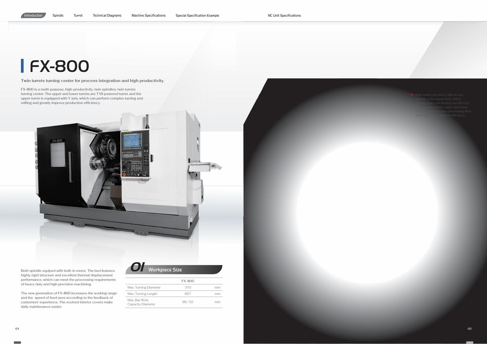
Both turret can mill or drill on one spindle at the same time, which means users can flexibly use the tool configuration of the upper and lower turrets, to reduce non-processing time and improve production efficiency.
02
mm
mm
mm
Workpiece Size 01Max. Turning Diameter
Max. Turning Length
Max. Bar Work Capacity Diameter
FX-800
310
657
65 / 52
FX-800 is a multi-purpose, high-productivity, twin spindles, twin turrets turning center. The upper and lower turrets are T16 powered turret, and the upper turret is equipped with Y axis, which can perform complex turning and milling and greatly improve production efficiency.
Both spindle equiped with built-in motor, The bed features highly rigid structure and excellent thermal displacement performance, which can meet the processing requirements of heavy duty and high precision machining.
The new generation of FX-800 increases the working range and the speed of feed axes according to the feedback of customers' experience. The evolved interior covers make daily maintenance easier.
Twin turrets turning center for process integration and high productivity.

03 04
TAIWAN TAKISAWA is committed to the basic research of machinery, through the finite element method (FEM) analysis to achieve higher machine rigidity and excellent thermal deformation performance.
The upper turret, lower turret and right spindle adopt independent linear slide rails. Since the lower turret and the right spindle are not in the same pair of railway, the rigidity of the right spindle can be improved. In addition, both turret can cut on the left spindle and right spindle, which greatly improves the flexibility and efficiency of use.
Introduction Spindle Turret Machine SpecificationsTechnical Diagrams Special Specification Example NC Unit Specifications
mm
m / min
mm
m / min
mm
m / min
mm
m / min
Travel & Rapid Traverse 02X1/X2-Axis Travel
X1/X2-Axis Rapid Traverse
Z1/Z2-Axis Travel
Z1/Z2-Axis Rapid Traverse
Y-Axis Travel
Y-Axis Rapid Traverse
B-Axis Travel
B-Axis Rapid Traverse
215 / 215
20 / 20
750 / 745
20 / 20
± 50
10
730
20
FX-800
The guideways introduce the concept of hybrid design. The X-axes and Y-axis with box ways which provide good vibration attenuation and dynamic rigidity. The Z-axes and B-axis with roller linear guides to achieve high precision, high rigidity and high speed.

05 06
SingleTurret
TwinTurret
Non-working Time Working Time
Cycle Time
Cycle Time
Introduction Spindle Turret Machine SpecificationsTechnical Diagrams Special Specification Example NC Unit Specifications
1030
125
105
Backward Tool
03 Working Area
04 Simultaneous Turning and Milling with Upper and Lower Turret
Sample Workpiece(S45C Ø56 x L63)
PRODUCTIVITY
Spindle
Spindle Output Diagram
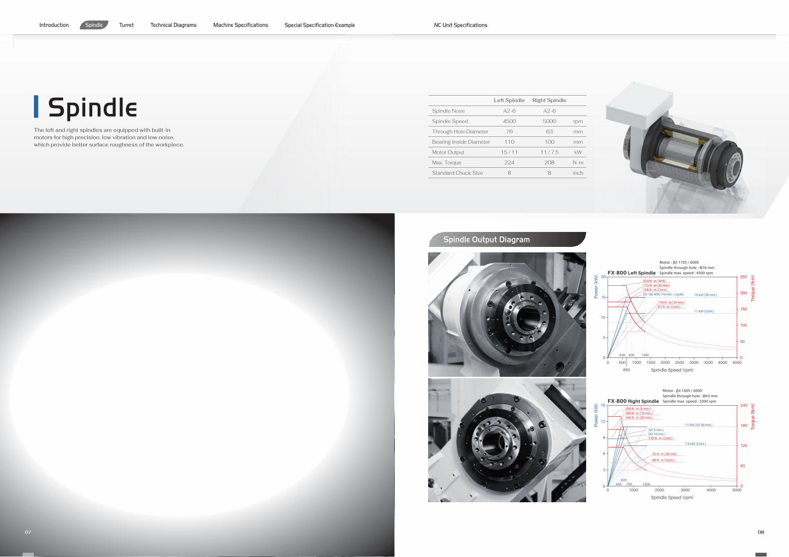
The left and right spindles are equipped with built-in motors for high precision, low vibration and low noise, which provide better surface roughness of the workpiece.
Spindle Nose
Spindle Speed
Through Hole Diameter
Bearing Inside Diameter
Motor Output
Max. Torque
Standard Chuck Size
rpm
mm
mm
kW
N · m
inch
A2-6
4500
76
110
15 / 11
224
8
Left Spindle
A2-6
5000
63
100
11 / 7.5
208
8
Right Spindle
07 08
Introduction Spindle Turret Machine SpecificationsTechnical Diagrams Special Specification Example NC Unit Specifications
FX-800 Left Spindle
Motor : βiI 170S / 6000Spindle through hole : Φ76 mmSpindle max. speed : 4500 rpm
Po
wer
(kW
)
Spindle Speed (rpm)
Torq
ue
(N·m
)
0
50
100
150
200
25020
15
10
5
00 500
640 1300
1000 1500 2000 2500 3000 3500 4000 4500
665
830
224 N · m [40%]173 N · m [30 min.]158 N · m [Cont.]
S3 / S6 40% [10 min. / cycle] 15 kW [30 min.]
11 kW [Cont.]
110 N · m [30 min.]81 N · m [Cont.]
FX-800 Right Spindle
Motor : βiI 160S / 6000Spindle through hole : Φ63 mmSpindle max. speed : 5000 rpm
Po
wer
(kW
)
Spindle Speed (rpm)
Torq
ue
(N·m
)15 240
000
180
120
60
12
9
6
3
1000 2000 3000 4000 5000
11 kW [S2 30 min.]
7.5 kW [Cont.]
505 750620
[S2 5 min.][S2 10 min.]
1500
115 N · m [Cont.]
140 N · m [30 min.]169 N · m [10 min.]208 N · m [5 min.]
70 N · m [30 min]
48 N · m [Cont.]

Turret
Number of Tools
OD Tool Shank Dimension
ID Tool Shank Diameter
Milling Shank Diameter
Milling Spindle Speed
Motor Output
Max. Torque
mm
mm
mm
rpm
Kw
N · m
16
25
40
20
4000
5.5 / 3.7
65.4
T16 Turret
Special Tool Holders
Gear Hobbing Broaching Power Skiving Adjustable Angle Milling
Spindle Output Diagram
Curvic Coupling O.D. 280 mm performs high rigidity and accuracy
Ready for 70 bar hi-pressure coolant
Easy to grease up
01
02
03
01 02 03 04
Turret Structure
01
0203
Euipped with 16 stations power turrets, which can handdle combined machining such as milling, drilling and tapping. Inside the turret, the large diameter of coupling gear set with curvic tooth profile provides high rigidity and high accurcy.
10
Introduction Spindle Turret Machine SpecificationsTechnical Diagrams Special Specification Example NC Unit Specifications
09
FX-800 Milling Spindle
Motor : βiI 3 / 12000-BMilling spindle max. speed : 4000 rpm
Spindle Speed (rpm)
Po
wer
(kW
)
Torq
ue
(N·m
)
0
2
4
6
8
0 1000 2000 3000 40000
20
40
60
80
65.4 N · m[15 min.]
5.5 kW [S2 15 min., S3 / S6 25%]
3.7 kW [S1 Cont.]
8031071 2410
44 N · m[60 min.]
33 N · m[Cont.]
4.1 kW
2.9 kW
[S2 60 min., S3 / S6 40%]

50
X2
Axi
s R
ef. P
oint
300
B Axis St. 730
Max.125
Max.105
Z1 Axis Ref. Point 831 105
81 Z1 Axis St. 750
142 Max. Turning Length 657 7
35
X1
Axi
s R
ef. P
oint
300
105
99
Z2 Axis Ref. Point 844
Z2 Axis St. 745
142Z2 Max. Turning Length 670
X1
Axi
s St
. 215
25
185
45
20
X2
Axi
s St
. 215
185
1030
80
109
NB-208A6
N-208A6
Interference
Travel Range
Tooling System
Machine Dimensions
11 12
Introduction Spindle Turret Machine SpecificationsTechnical Diagrams Special Specification Example NC Unit Specifications
1330
845
1284Opening width
955
600
2175
574
B
3400
150
791
170
1379
2175
234016
50
78
275
415
A
Op
enin
gd
epth
935
685 1330
201
O.D Tool HolderTurning Tool
Boring Bar
□25 mm
Drill SocketMT. 4 / 3 / 2 / 1
Short Drill SocketMT. 1
Drill
U-DrillU-Drill Holder
Faceing Holder
Boring Bar Bush
Short Boring Bar Bush
Ø32 / 25 / 20 / 16 / 12 / 10 / 8 / 6
Ø32 / 25 / 20 / 16 / 12 / 10 / 8 / 6
U-Drill SocketØ32 / 25 / 20
ColletER32 (Ø1 ~ Ø20)
X-Axis Milling Holder
Z-Axis Milling Holder
Ø40
□25 mmCutting Tool Cutting Tool Holder
Boring Bar / Drill Holder
Chip Conveyor Dimension
1236
1336
1540
1561
782
815
1012
1205
Standard
CE
Italy
USA
BA
∅760
470 300
58
58
30
25
Std.
Tur
ning
Dia
∅22
9
20
30
Std.
turn
ing
dia
∅22
9
20
∅760
X2 Axis st. 215 X1 Axis st. 215
Max
. Tur
ning
Dia
. ∅31
0
20Lower Turret (T2)
25
Spindle Center
80
∅230
∅210
535
470300
535
Upper Turret (T1)
∅230
∅210
∅20
80 3590
∅20
35 8090
7525
103
6380105
63
143
105
∅40
∅40
5050
Y A
xis
St. 1
00
5
31.7
5

Standard and Optional AccessoriesMachine SpecificationsItem FX-800
Max. Swing
Standard Turning Diameter
Max. Turning Diameter
Max. Turning Length
Max. Bar Work Capacity
Dist. Between Centers
X1/X2-Axis Travel
Z1/Z2-Axis Travel
Y-Axis Travel
B-Axis Travel
Spindle Speed
Spindle Nose
Through Hole Diameter
Bearing Diameter
Spindle Speed
Spindle Nose
Through Hole Diameter
Bearing Diameter
Number of Tools
OD Tool Shank Dimension
ID Tool Shank Diameter
Milling Shank Diameter
Spindle Speed
X1/X2-Axis Rapid Traverse
Z1/Z2-Axis Rapid Traverse
Y-Axis Rapid Traverse
B-Axis Rapid Traverse
Left Spindle Motor
Right Spindle Motor
Milling Spindle Motor
Index Motor
X1/X2-Axis Servo Motor
Z1/Z2-Axis Servo Motor
Y-Axis Servo Motor
B-Axis Servo Motor
Height
Width
Depth
Weight
mm
mm
mm
mm
mm
mm
mm
mm
mm
mm
rpm
mm
mm
rpm
mm
mm
mm
mm
m/min
m/min
m/min
m/min
kW
kW
kW
kW
kW
kW
kW
kW
mm
mm
mm
kg
Capacity
Travel
LeftSpindle
Feedrate
Machine Size
RightSpindle
Turret
Motor
310
229
310
657
65 / 52
1030
215 / 215
750 / 745
±50
730
4500
A2-6
76
110
5000
A2-6
63
100
T16 + T16
25
40
20
4000
20 / 20
20 / 20
10
20
15 / 11
11 / 7.5
5.5 / 3.7
1.2
3.0 / 2.5
2.5 / 2.5
2.5
2.5
2340
3550
2334
11000
Standard Optional Nope
Accessories FX-800
13 14
Built-In Motor Left Spindle
Built-In Motor Right Spindle
O.D Tool Holder (2 PCS)
Face Tool Holder (2 PCS)
U-Drill Tool Holder (2 PCS)
Boring Bar Tool Holder (8 PCS)
Boring Bar Bush (Ø6, Ø8, Ø10, Ø12)
Boring Bar Bush (Ø16, Ø20, Ø25, Ø32)
U-Drill Bush (Ø16, Ø20, Ø25, Ø32)
Short Boring Bar Bush (Ø6, Ø8, Ø10, Ø12)
Short Boring Bar Bush (Ø16, Ø20, Ø25, Ø32)
Drill Bush (MT.1, MT.2, MT.3, MT.4)
Short Drill Bush (MT.1)
X-Axis Milling Holder (2 PCS)
Z-Axis Milling Holder (2 PCS)
Automatic Tool Setter
Manual Tool Setter
Linear Scales
Coolant Pump (450W)
Coolant Pump (715W, 750W, 900W, 1400W)
Coolant Chiller
Nut Cooling Ball Screw
Hydraulic System
Hydraulic Oil Cooling
Hydraulic Pressure Sensor
Lubrication System
Hydraulic Chuck
Collet Chuck
Foot Switch
LED Interior Light
LED Signal Tower
Chip Cart
Right Side Chip Conveyor
Parts Catcher
Automatic Bar Feeder and Interface
Auto Door
Safety Door Switch
Safety Light Curtain
Air Blow
Oil Skimmer
Oil Mist Collector
Parts Counter
Automatic Power-Off
Introduction Spindle Turret Machine SpecificationsTechnical Diagrams Special Specification Example NC Unit Specifications

Special Specification ExampleLatheGantry LoaderWorkpiece Feeder
Layout VariationsParts Catcher Parts Pusher
Part Catcher Working Range
A B C
Peripheral Equipment
Highly Accurate Optional Equipment
High Speed Gantry Loader System
Turn-Key Solution
Pallet
Loading Weight
Max. Height
Worker Feeder Width
pcs
kg
mm
mm
16
40
450
610
X-Axis Rapid Traverse
Z-Axis Rapid Traverse
m / min
m / min
180
150
O.D
Length
Weight
mm
mm
kg
160
100
3 (x2)
Feedrate
Working Size
Gantry Loader Specifications
Work Feeder Specifications
Linear Scales
Automatic l Manual Tool Setter
Nut Cooling Ball Screw
High Pressure Coolant
Hydraulic Oil Cooling
Cutting Fluid Cooling
01
02
03
04
05
06
There are special requirements for precise machining accuracy and it is necessary to use approved high-precision optional equipment.
Please contact us for advice on these options.
Measuring Unit
Camera Positioning Unit
Washing Unit
Quality Chute
Part Catcher Specifications
Max. Parts Dia.
Max. Parts Length
Max. Parts Weight
mm
mm
kg
65
135
3.5
Smaller ClampingDiameter Range
(By Exchanging Jaws)
Default ClampingDiameter Range
15 16
Option to use jaws or boxes
Introduction Spindle Turret Machine SpecificationsTechnical Diagrams Special Specification Example NC Unit Specifications
377
MAX. 135
With part pusher, the maximum speed of sub-spindle will be limited to 4000 rpm.
01
04 05 06
02 03
MAX. ∅40
MIN. ∅8
MAX. ∅65
MIN. ∅40

NC Unit Specifications
Rapid Traverse Override (F0, 25%, 50%, 100%)
Feed Per Minute
Feed Per Revolution
Constant Tangential Speed Control
Cutting Feedrate Clamp
Automatic Acceleration / Deceleration
Rapid Traverse Bell-Shaped Accel / Decel
Linear Accel / Decel After Feedrate Interpolation
Feedrate Override (15 Steps)
Jog Override (15 Steps)
Override Cancel
Manual Feed Per Revolution
Feed Function
Program Input
Miscellaneous Function / Spindle Functions
Data I/O
Tape Code (EIA / ISO Auto Recognition)
Label Skip
Parity Check
Control In / Out
Optional Block Skip, 1 Piece
Optional Block Skip (2 to 9 Pieces)
Program Number O4 Digits
Program File Name 32 Characters
Sequence Number N5 Digits
Sequence Number N8 Digits
Absolute / Incremental Command
Decimal Point Input / Pocket Calculator Type Decimal Point Input
Diameter / Radius Programming (X-Axis)
Coordinate System Setting (G50)
Auto coordinate System Setting
Drawing Dimension Direct Input
G-Code System A
G-Code System B / C
Chamfering / Corner R Programming
Programmable Data Input
Sub Program Call (10 Levels)
Custom Macro
Additional Custom Macro Common Variables
Single Canned Cycle
Combined Canned Cycle
Combined Canned Cycle II
Drilling Canned Cycle
Arc Radius Programming
Macro Executor
Coordinate System Shift
Coordinate System Shift Direct Input
M Function (M3 Digits)
Second Miscellaneous Function (B Function)
Spindle Functions (S4 Digits)
Constant Surface Speed Control
Spindle Orientation
Rigid Tap (Spindle Center)
Rigid Tap (Rotary Tool)
RS-232C Interface for 1 ch
Fast Data Server
External Message
External Workpiece Number Search
Memory Card I/O
Specifications · ContentsT Function (T2 + 2 Digits)
Tool Offsets, 32 Pieces
Tool Offsets, 64 Pieces
Tool Offsets, 99 Pieces
Tool Offsets, 200 Pieces
Tool Offsets, 400 Pieces
Tool Geometry Size Data, 100 Pieces
Tool Position Offset
Tool Diameter / Nose R Compensation
Tool Geometry / Wear Compensation
Tool Offset Counter Input
Tool Offset Measured Value Direct Input
Tool Offset Measured Value Direct Input B
Tool Life Management
Tool Functions / Tool Offset Functions
Accuracy Offset Functions
Editing
Backlash Compensation
Backlash Compensation by Rapid Traverse / Feedrate
Part Program Memory Capacity 128K byte (320 m)
Part Program Memory Capacity 320K byte (800 m)
Part Program Memory Capacity 512K byte (1280 m)
Part Program Memory Capacity 1M byte
Part Program Memory Capacity 2M byte
Registrable Programs, 400 Programs
Registrable Programs, 800 Programs
Registrable Programs, 1000 Programs
Program Editing
Program Protection
Extended Program Editing
Background Editing
FX-800
FX-800FX-800
FX-800
Status Display
Clock Function
Current Position Display
Program Comment Display (31 Characters)
Parameter Setting and Display
Alarm Display
Alarm Log Display
Operator Message Log Display
Operation Message Log Display
Run Hours and Parts Count Display
Actual Speed Display
Actual Spindle Speed and T Code Display
Floppy Cassette Directory Display
Grouped Directory Display and Punching
Servo Adjustment Screen
Maintenance Information Screen
Data Protection Key, 1 Kind
Help Function
Self Diagnostic Function
Scheduled Maintenance Screen
Hardware & Software System Configuration Display
Graphic Display
Dynamic Graphic Display
English
Japanese (Kanji)
Other Language
Display Language Dynamic Switching
Setting / Display
Display Languages
Specifications · ContentsSpecifications · Contents
Standard OptionalNope
SpecialParameter setting is required
It provides simple operation and convenient function.
Smart Work Manager
This function can set tool life and wear limit to manage all tools.Tool Life Manager01
Detecting max load to check tool status.Load Monitor02
It offer parts counter, program history, operate time for today or this month.Parts and Machine Manager03
01
0302
(Option)
Introduction Spindle Turret Machine SpecificationsTechnical Diagrams Special Specification Example NC Unit Specifications
17 18
Specifications · Contents
0i-TF
8.4" Color LCD
10.4" Color LCD
15" Color LCD
Controller
NC Unit
Safety Device
Controlled Axes
Operation
Interpolating Functions
Front Door Interlock
Front Door Locking Mechanism
Safety Relay
Control Panel Breaker with Tripper
Least Input Increment
Maximum Programmable Dimension (± 999999.999)
Least Input Increment C
Inch / Metric Selection
Interlock
Machine Lock
Emergency Stop
Stored Stroke Check 1
Stored Stroke Check 2, 3
Stroke Limit Check Before Movement
Chuck Tailstock Barrie
Mirror Image (Each Axis)
Chamfering ON / OFF
Overload Detection
Position Switch
Poitioning (G00)
Exact Stop Mode (G61)
Tapping Mode (G63)
Cutting Mode (G64)
Exact Stop (G09)
Linear Interpolation (G01)
Circular Interpolation (G02 / 03)
Dwell (G04)
Polar Coordinate Interpolation
Cylindrical Interpolation
Thread Cutting
Multiple Thread Cutting
Thread Cutting Cycle and Retraction
Continuous Thread Cutting
Variable Lead Thread Cutting
Reference Point Return (G28)
Reference Point Return Check (G27)
2nd Reference Point Return (G30)
3rd, 4th Reference Point Return
Auto Run (Memory)
MDI Run
DNC Run
DNC Run with Memory Card
Program Number Search
Sequence Number Search
Sequence Number Collation and Stop
Wrong Operation Preventive
Buffer Register
Dry Run
Single Block
Jog Feed
Manual Reference Point Return
Dogless Reference Point Setting
Manual Handle Feed, 1 Unit