task7: nustar2 - design and prototype construction of a radiation-resistant magnet c. mühle gsi...
TRANSCRIPT
Task7: NUSTAR2 - Design and Prototype Task7: NUSTAR2 - Design and Prototype Construction of a Radiation-Resistant MagnetConstruction of a Radiation-Resistant Magnet
C. Mühle
GSI
Task leader: G. Moritz /GSI
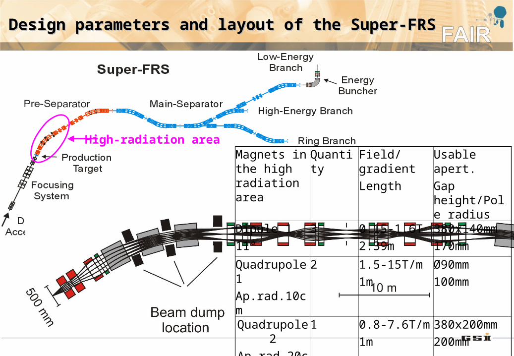
High-radiation area
Design parameters and layout of the Super-FRSDesign parameters and layout of the Super-FRS
Magnets in the high radiation area
Quantity Field/gradient
Length
Usable apert.
Gap height/Pole radius
Dipole 1
11°
3 0.15-1.6T
2.39m
380x140mm
170mm
Quadrupole 1
Ap.rad.10cm
2 1.5-15T/m
1m
Ø90mm
100mm
Quadrupole 2
Ap.rad.20cm
1 0.8-7.6T/m
1m
380x200mm
200mm
Sextupole 1 2 1.5-14T/m2
0.6m
380x200mm
200mm
Recap of first yearRecap of first year
Original idea:
Use of superconducting radiation resistant dipoles
Investigation of radiation loads:
Heat load on the cryogenic system for a 5 ton magnet: ≈ 2.3 kW (expected FAIR cryogenic power: 20 kW) => economic operation not possible
Decision
Normal conducting magnets with mineral insulated cable (MIC)
Surveying and alignment system for high-radiation areas
Not directly influenced by this decision
=> Main work in 2006 was dedicated to the conceptual design of a dipole with MIC
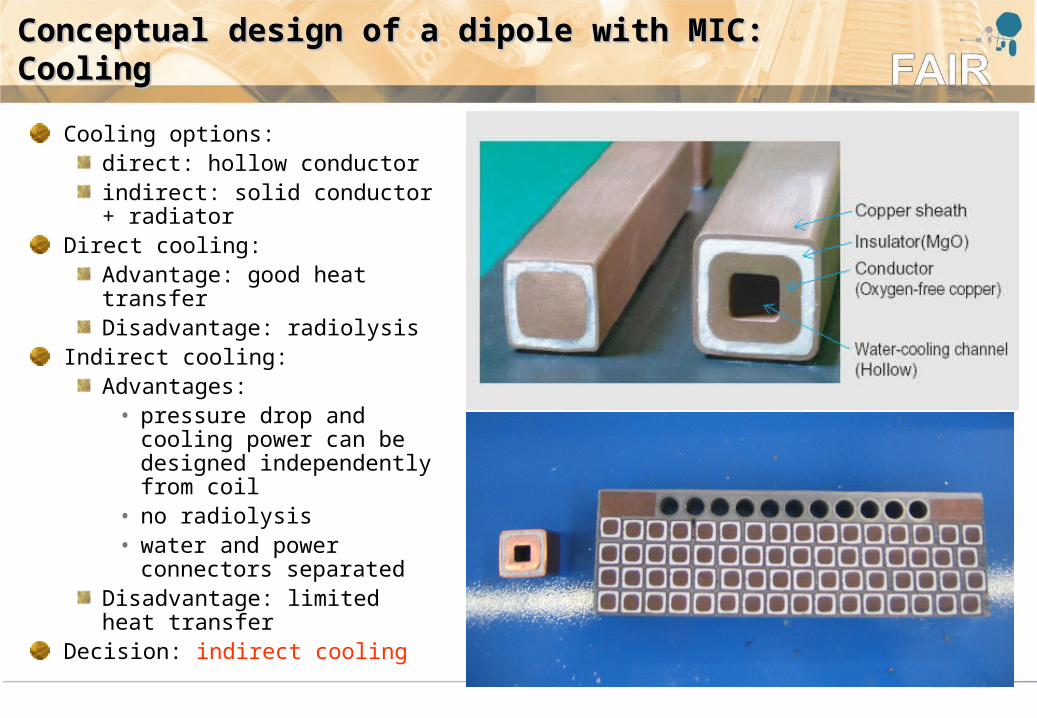
Conceptual design of a dipole with MIC: Conceptual design of a dipole with MIC: CoolingCooling
Cooling options:direct: hollow conductorindirect: solid conductor + radiator
Direct cooling:Advantage: good heat transferDisadvantage: radiolysis
Indirect cooling:Advantages:
• pressure drop and cooling power can be designed independently from coil
• no radiolysis• water and power
connectors separatedDisadvantage: limited heat transfer
Decision: indirect cooling

Conceptual design of a dipole with MIC: CoilConceptual design of a dipole with MIC: Coil
Conductor:Cable Size 19mm x 19mm Sheath Thickness 1 mmInsulation Thickness 1 - 1.5 mmCond. Area 190 mm2 Unit Length 100m
Radiator:Copper plate 12 mm thickStainless steel tube 10x1mm
Coil system:2 x 192 turns, 12 columns, 2 x 16 layers 2 x 8 double pancakes≈ 100 m conductor per single pancaketotal conductor length ≈ 3.2 km
Conceptual design of a dipole with MIC: YokeConceptual design of a dipole with MIC: Yoke
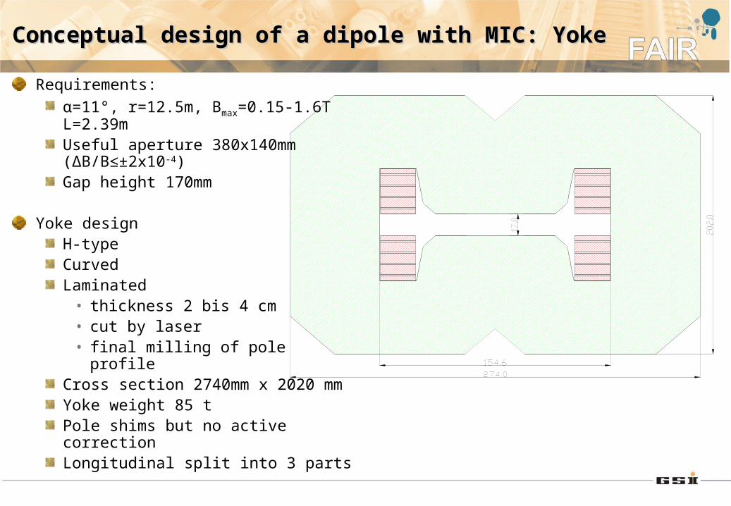
Requirements:
α=11°, r=12.5m, Bmax=0.15-1.6T L=2.39mUseful aperture 380x140mm (ΔB/B≤±2x10-4)Gap height 170mm
Yoke designH-typeCurvedLaminated
• thickness 2 bis 4 cm• cut by laser• final milling of pole profile
Cross section 2740mm x 2020 mmYoke weight 85 tPole shims but no active correctionLongitudinal split into 3 parts
Conceptual design of a dipole with MIC: Dipole Conceptual design of a dipole with MIC: Dipole operationoperation
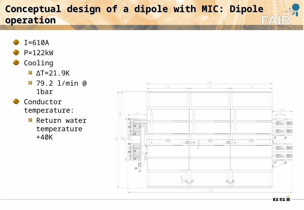
I=610A
P=122kW
Cooling
ΔT=21.9K
79.2 l/min @ 1bar
Conductor temperature:
Return water temperature +40K
Construction of a prototype dipole with MICConstruction of a prototype dipole with MIC
To be done in the remaining project time:
Manufacturing design
Production of tooling and first (test) double pancake
Production of full coil
Production of yoke
Assembly of final magnet
Time scale
≈ 1 year => close to the limit, but still feasible
Cost estimation of prototype magnet incl. tooling: 1.5 M€
Budget
This task: 568 k€ (50%EU,50%GSI)
Budget gap: ≈ 950 k€• Redirect money from other tasks• Finance remaining gap by GSI
SurveyingSurveying and alignment system for high-radiation areasand alignment system for high-radiation areas
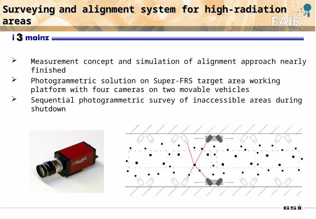
Measurement concept and simulation of alignment approach nearly finished Photogrammetric solution on Super-FRS target area working platform with four
cameras on two movable vehicles Sequential photogrammetric survey of inaccessible areas during shutdown
Surveying and alignment system for high-radiation Surveying and alignment system for high-radiation areasareas
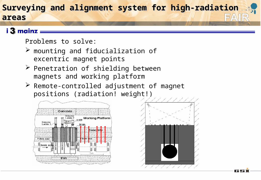
Problems to solve: mounting and fiducialization of excentric magnet
points Penetration of shielding between magnets and
working platform Remote-controlled adjustment of magnet positions
(radiation! weight!)