tav varsity exposed - upload2.evocdn.co.ukupload2.evocdn.co.uk/tavistock/uploads/asset_file/... ·...
TRANSCRIPT
REF: JS | 07.14 V1.00
Product codeVarsity Dual FunctionExposed Shower System
Varsity Single FunctionExposed Shower SystemSVA1712
Product codeSVA1813
Varsity Exposed Shower SystemsInstallation & aftercare instructions
Please retain for future reference
Customer ServicesTavistock, Brassmill Lane Trading Estate, Bath, BA1 3JFt. 01225 787 870 e. [email protected] w: www.tavistock-bathrooms.co.uk
VARSITYEXPOSED SHOWER SYSTEMInstallation & aftercare instructions
Please retain for future reference

Your exposed shower valve is a thermostatic mixer which incorporates a thermo-regulating cartridge to assure users of consistent showering temperatures. The valve has been designed & manufactured to comply with BS EN 1111:1999.This valve complies with the requirements of the above regulations and installation should be carried out in strict compliance with them.
Before installation the operating conditions of use must be checked. The table below contains details of the necessary conditions of operation. This valve is suitable for use with the following systems
• Gravity fed Hot & Cold (balanced pressures)• Gravity fed Hot & mains Cold (balanced pressures)• Unvented systems• Gas combination boiler• Pumped system
Note: On gravity systems the minimum Vertical distance (Drop) from the underside of the cold water storage tank to the shower valve must be 3 metres for single function showers and 5 metres for dual function showers. If water supply is fed by gravity then supply pressure should be verified to ensure the conditions of use are appropriate for the valve
Recommended outlet temperaturesThe BuildCert TMV scheme recommends the following set maximum mixed water outlet temperatures for use in all premises:41°C for showers;The mixed water temperatures must never exceed 46°C.The maximum mixed water temperature can be 2°C above the recommended maximum set outlet temperatures.
Note: 46°C is the maximum mixed water temperature from the bath tap. The maximum temperature takes account of the allowable temperature tolerances inherent in thermostatic mixing valves and temperature losses in metal baths. It is not a safe bathing temperature for adults or children.
The British Burns Association recommends 37 to 37.5°C as a comfortable bathing temperature for children. In premises covered by the Care Standards Act 2000, the maximum mixed water outlet temperature is 43°C.
The thermostatic mixing valve will be installed in such a position that maintenance of the TMV and its valves and the commissioning and testing of the TMV can be undertaken.
The fitting of strainers is recommended as close as is practicable to the water supply inlets of the thermostatic mixing valve.
HIGH PRESSURE
Maximum Static Pressure - BAR
Flow Pressure, Hot & Cold - BAR
Hot Supply Temperature - °C
Cold Supply Temperature - °C
10
0.3 to 5
55 to 65
Equal to or less than 25°C
Introduction
Operating Conditions of Use
2 11

We advise that the valves, check valves and filters be regularly serviced particularly in hard water areas. The check valves along with the filters are contained in the retaining nut. The water supplies must be isolated remotely from the valve before removal.
Valves should be tested against the original set temperature results once a year. When testing is due the following performance checks shall be carried out.
1. Measure the mixed water temperature at the outlet.2. Carry out the cold fail-safe shut off test by isolating the cold water supply to the TMV, wait for 5 seconds if water
is still flowing check that the temperature is below 46 degrees C.3. If there is no significant change to the set outlet temperature (+/- 2°C or less change from the original setting) and
the fail safe shut off is functioning, then the valve is working correctly and no further service work is required.
If further maintenance should be required contact Roper Rhodes for details. Please see contact details on the back page of this document.
Maintenance
The valve must be installed so that it is readily accessible for commissioning and maintenance. The valve must be installed with isolation valves on both the hot and cold water systems as close as possible to the valve; so as to allow the valve to be commissioned and tested correctly. The valve is fitted with integral check valve cartridges which command the water supply, therefore the thermostatic valve is protected against cross-flow due to unbalanced line pressures as required by the Water Supply (Water Fittings) Regulations 1999.
Most problems associated with the operation of thermostatic shower valves are caused by debris in the new pipe work getting into the thermostat. These problems are easily avoided by thoroughly flushing the pipe work BEFORE the shower valve is fitted.
Valve Installation Guidelines and Compliance
General Dimension
10 3
200
340
Dual Function
Single Function
200
340
148
148mm - 155mm
200
215 148
200
215
10 Year Guarantee
We have complete confidence in this Tavistock product and as such it is offered with a 10-year guarantee against defects in manufacture. This valve must be fitted by a competent installer. If in doubt seek advice from a qualified professional. The guarantee requires that this product be used in the manner for which it was intended and that it is installed & maintained in accordance with the fitting instructions and local water bylaws. The guarantee covers products in domestic use only. Always ensure this product is fully tested before concealing valves into the wall. On installation ensure that the valve and valve inlet threads can be removed or serviced in accordance with UK regulations. The guarantee is invalidated should the valve be damaged by water borne debris. Make sure that supply pipes are clear of any debris prior to installation, this is particularly important on new plumbing installations. In the unlikely event that this product should fail during the guarantee period we will either replace the faulty part or the complete unit as appropriate. This guarantee excludes normal wear and tear. This guarantee covers failure of the thermostatic cartridge within the first 2 years of purchase only. Replacement cartridges are available to purchase by contacting the Tavistock Customer Service team. Failure to follow the terms outlined above will invalidate this guarantee. Proof of purchase will be required to validate any guarantee claims.
148mm - 155mm
If you require further assistance beyond the guide below contact the help line on 01225 787 870
PROBLEM
Shower will not run hot enough when first installed
Cold water running back through the valve into the hot water system.
Shower only runs cold.
SOLUTION
Check for debrisCheck hot water temperature and boiler function
Check the filters and check valves are functioning correctly.
Check hot and cold pipework is installed to correct inlet on the valve
Whilst this item has a high quality durable finish, it should nevertheless be treated with care. Surfaces should be cleaned using only a soft damp cloth and clean water & dried using a soft cotton cloth. Bath / shower cleaning products, even non-scratch ones could damage the finished surface.
Trouble-shooting
Aftercare Instructions
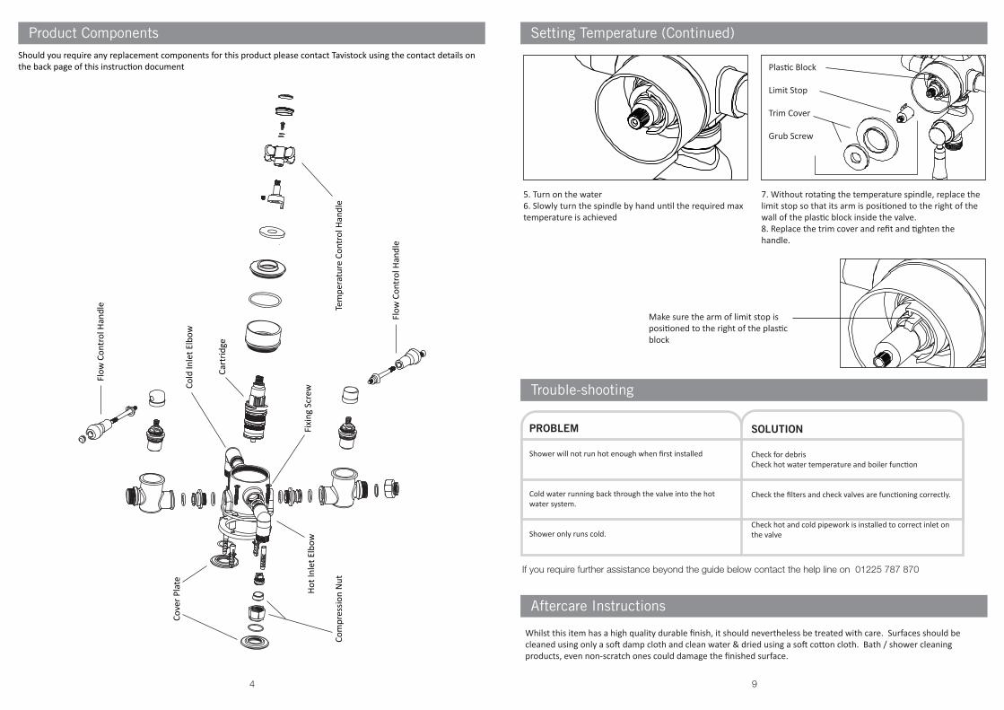
Should you require any replacement components for this product please contact Tavistock using the contact details on the back page of this instruction document
5. Turn on the water6. Slowly turn the spindle by hand until the required max temperature is achieved
Plastic Block
Limit Stop
Trim Cover
Grub Screw
7. Without rotating the temperature spindle, replace the limit stop so that its arm is positioned to the right of the wall of the plastic block inside the valve.8. Replace the trim cover and refit and tighten the handle.
Make sure the arm of limit stop is positioned to the right of the plastic block
Flow
Con
trol
Han
dle
Tem
pera
ture
Con
trol
Han
dle
Cart
ridge
Flow
Con
trol
Han
dle
Hot I
nlet
Elb
ow
Cold
Inle
t Elb
ow
Com
pres
sion
Nut
Cove
r Pla
te
Fixi
ng S
crew
94
Product Components Setting Temperature (Continued)
Commissioning
It is important that incoming water supplies conform to the requirements specified for pressure and temperature. Assure that supply water conditions satisfy any guidance information for the control of bacteria and that the designation of the supplied valve suits the application. Do not continue commissioning until supplies are correct and stable considering variation caused by other service users.
Use a calibrated thermometer for testing incoming and mixed water.
1. Record temperature of the incoming hot and cold supply.2. Record temperature of mixed discharge at maximum draw off rate.3. Record temperature of mixed discharge at minimum draw off rate.4. Isolate the cold water supply and measure the mixed water temperature as the cold water failure device reacts.
This should deviate by no more than + 2°C of the initial maximum set point. Restore the cold supply and measure the stabilised mixed water temperature. This must not deviate by more than + / - 2°C of the initial set recorded result. Record these findings.
5. Record the measuring equipment used for the measurements.
The above records must be retained and updated during the service life of the valve.
If there is a residual flow during the commissioning or the annual verification (cold water supply isolation test),then this is acceptable providing the temperature of the water seeping from the valve is no more than 2˚Cabove the designated maximum mixed water outlet temperature setting of the valve.Temperature readings should be taken at the normal flow rate after allowing for the system to stabilise. The sensing part of the thermometer probe must be fully submerged in the water that is to be tested.Any TMV that has been adjusted or serviced must be re-commissioned and re-tested in accordance with themanufacturers' instructions.
The installation of thermostatic mixing valves must comply with the requirements of the Water Supply (WaterFittings) Regulations 1999.
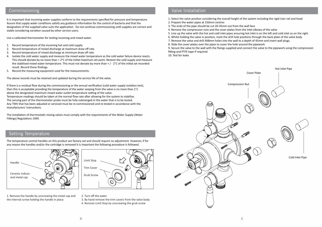
The temperature control handles on this product are factory set and should require no adjustment. However, if for any reason the handles and/or the cartridge is removed it is important the following procedure is followed.
Handle
Ceramic Indices and metal cap
1. Remove the handle by unscrewing the metal cap and the internal screw holding the handle in place.
Limit Stop
Trim Cover
Grub Screw
2. Turn off the water3. By hand remove the trim covers from the valve body4. Remove Limit Stop by unscrewing the grub screw
Setting Temperature
Valve Installation
1. Select the valve position considering the overall height of the system including the rigid riser rail and head2. Prepare the water pipes at 150mm centres3. The ends of the pipe should be cut 20-35mm out from the wall face4. Remove the compression nuts and the cover plates from the inlet elbows of the valve5. Line up the valve with the hot and cold inlet pipes ensuring hot inlet is on the left and cold inlet os on the right6. Whilst holding the valve in position, mark the drill hole positions through the back plate of the valve body7. Remove the valve and drill 4X8mm holes into the wall to a depth of 45mm and insert wall plugs.8. Slide the cover plates over the pipes to cover the hole around the pipework9. Secure the valve to the wall with the fixings supplied and connect the valve to the pipework using the compression fitting and PTFE tape if required10. Test for leaks
58
Cold Inlet Pipe
Hot Inlet PipeCover Plate
Compression Nut
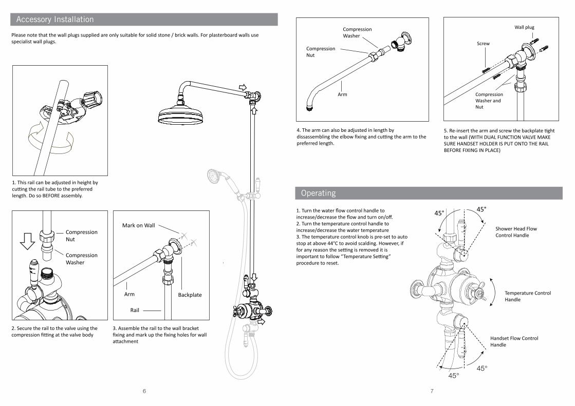
CompressionWasher
CompressionNut
2. Secure the rail to the valve using the compression fitting at the valve body
3. Assemble the rail to the wall bracket fixing and mark up the fixing holes for wall attachment
5. Re-insert the arm and screw the backplate tight to the wall (WITH DUAL FUNCTION VALVE MAKE SURE HANDSET HOLDER IS PUT ONTO THE RAIL BEFORE FIXING IN PLACE)
Mark on Wall
Screw
Backplate
CompressionWasher and Nut
CompressionWasher
CompressionNut
Arm
Rail
Arm
4. The arm can also be adjusted in length by dissassembling the elbow fixing and cutting the arm to the preferred length.
1. Turn the water flow control handle to increase/decrease the flow and turn on/off.2. Turn the temperature control handle to increase/decrease the water temperature3. The temperature control knob is pre-set to auto stop at above 44°C to avoid scalding. However, if for any reason the setting is removed it is important to follow “Temperature Setting” procedure to reset.
45°
Shower Head Flow Control Handle
Handset Flow Control Handle
Temperature Control Handle
Please note that the wall plugs supplied are only suitable for solid stone / brick walls. For plasterboard walls use specialist wall plugs.
1. This rail can be adjusted in height by cutting the rail tube to the preferred length. Do so BEFORE assembly.
45°
45°45°
Accessory Installation
Operating
Wall plug
The valve should be installed in accordance with the water bye-laws. For further details refer to the latest copy of Water Bye-laws guide or your local water authority.
1. Prepare the water supply pipes (hot on the left and cold on the right) at the identified height with a width of 150mm centers.2. Make the ends of pipes 20-25mm out from the face of wall.3. Remove the compression nuts and the back plates from the inlet elbows of valve.4. Line up the valve with the hot and cold inlet pipes making sure the correct elbow meet the correct pipe (refer to diagram)5. Whilst holding the valve in position, mark where the holes are on the wall.6. Remove the valve and drill 4X8mm holes into the wall where you marked to a depth of 45mm and insert wall plugs.7. Slide the cover plates under the compression nuts and position each pipe with the cover plate and nuts against the wall.8. Push the valve over each pipe and make them into the back plate.9. Tighten the two nuts on both inlets.
76