tcm 500 ndvi turf color meter - specmeters.com · 6 allow the temperature of the tcm 500 meter to...
TRANSCRIPT
TCM 500 NDVI Turf Color Meter PRODUCT MANUAL
Item # 2975NDVI
®
2
Contents General Overview 3
Computer Interface/Changing the Battery 5
Initial Startup 6
Identifying the Correct Com Port 7
Connecting to a GPS Unit 8
Keypad Operation 11
Standard Reading Mode 14
Field Scout Software Toolbar 16
Meter Settings 18
Data Files 19
Meter Indexes 20
Specifications 22
ERROR messages 23
Appendix 1: Time Zone Corrections 24
Frequently Asked Questions 25
Service and Support 26
T-handle 10
Adjusting the Grass Index 21

3
General Overview
Turf grass quality is visually evaluated by human assessors based on a scale of 1 (poorest, the grass is dead) to 9 (ideal, the grass is of outstanding quality) using a common assessment method. A rating of 6 or greater indicates adequate turf quality. Because this evaluation practice is subjective, individual biases are inevitable and lead to some level of inconsistency, even among the most highly trained observers. This variability led to the need for a more objective evaluation technique. To answer this need, researchers have developed the Normalized Difference Vegetative Index (NDVI). The Field Scout TCM 500 “NDVI” Turf Color Meter measures reflected light from turf grass in the red (660 nm) and near infrared (850 nm -NIR) spectral bands. Because chlorophyll absorbs the red band (660 nm) of incoming radiation, the reflectance at that wavelength is relatively low due to the strong absorption of the light by the plant pigments. The high reflectance in the NIR (850 nm) band is caused by the cellular structure of the plant leaves, particularly the spongy mesophyll leaf structure. The meter also provides the user with the option of viewing a Grass Index calculated from NDVI. This index can be adjusted to match the user’s evaluation of that field.

4
Features • A measuring target approximately 3 inches (7.6 cm) in
diameter. • Consistent internal light source that negates the effects
of sunny versus cloudy conditions. • Red & NIR data is presented in three forms: Percent
reflectance (0.0 to 99.9) of Red and NIR, NDVI (0.000 to 1.000), and Grass Index (ie. 1.00 to 9.00).
• GPS/DGPS can be used - requires GPS/DGPS cable (item 2950CV5).
• A running average is calculated and displayed as multiple readings are taken.
• Data is stored in comma-delimited text files. They can be opened and processed with any spreadsheet, graphing, statistical, or word processing program.
• Optional T-handle extension to allow measurements to be taken while standing.

5
Computer Interface/ Changing the Battery
Software Installation Insert the CD for Field Scout software into your PC’s disk drive. If auto-start is not enabled on your computer, select Run from the Start menu and type D:\Setup.exe (Substitute the appropriate drive letter for your CD drive). Click OK and follow the instructions on the screen. The meter’s data port can be accessed by removing the plastic screw to the left of the handle. It is through this port that the meter is connected to either a PC or to a GPS unit. The meter must be turned off before attempting communication with the software. Connecting to a PC The Field Scout software comes with a black PC interface cable. This cable connects to the USB port of your com-puter and to the meter’s computer port. The meter’s con-figuration can be modified by clicking on the Meter Set-tings button (see Meter Settings, p. 18). The Com Port, Meter Type, Download, Clear Memory and Meter Set-tings buttons are explained in the Main Toolbar section (p. 16). Note: Prior to 2014, the meter was shipped with a gray cable that connected to a 9-pin serial port. This cable will still work but may require a USB-to-serial adapter.
Changing the battery The battery compartment is accessed by removing the 4 phillips head screws on the underside of the meter and re-moving the bottom plate. The TCM 500 meter is powered by a 9-V battery.

6
Allow the temperature of the TCM 500 meter to equilibrate with the turf environment prior to sampling. When the TCM 500 meter is first turned on, the battery strength (Battery at __ %) will appear on the LCD. The available battery power percentage assumes alkaline batteries are being used. If rechargeable NiCd batteries are installed, the available battery power will be more than displayed. If the data logging option has not been enabled, the unit will then proceed to the standard reading mode. In order to record data and global positioning system (GPS) coordinates, the data logger must first be enabled through the software (See p. 18). If the data logger has been enabled, battery strength and the amount of remaining memory (Memory __ % FULL) will be displayed. If GPS data is being recorded as well, the meter will display the status of the GPS signal. The meter will then proceed to the standard reading mode. IMPORTANT: The GPS unit must be powered up, have located the satellites and been connected to the meter before turning the meter on (see “Connecting to GPS Unit”, p. 8).
Initial Startup

7
T h e c o m p u t e r Communications Port to which the cable is c o n n e c t e d c a n b e identified by using a paper clip. 1. Disconnect the serial cable from the meter.
2. To bring up the Port Selection screen, click on the Com Port Button, select the com port to be tested and click the Port Test button. Click the Test Port Now button. If the message “Connection OK” is displayed, another device (such as a modem) is probably connected to that port. If the message “No Connection” is displayed, this port may be the one connected to your serial cable and you can proceed to the next step. 3. Place a paperclip on the end of the serial pin so that it touches both the tip of the pin and the metal area between the two black rings. Again click on the Test Port Now button. If the message “Connection OK” now appears, this is the com port connected to your serial cable.
paper clip or wire
Identifying the Correct Com Port
NOTE: The meter does not short-circuit the serial pin. Therefore, when the Test Port Now button is clicked while the meter is connected, the “No Connection” message will be displayed.

8
Connecting to a GPS Unit
The data logger function must be enabled using the Field Scout software in order to record a GPS signal (see “Meter Settings”, p. 18).
The GPS unit must be plugged into the TCM500 meter and working when the meter is first turned on. If a GPS signal is found at startup, the logger will search for a GPS signal for every reading. If no GPS signal is found when the meter is first turned on, the meter will not search for one when taking readings, thereby saving time when taking readings. In this case the LCD will display the No GPS Found message.
If the GPS signal is found while taking geo-referenced readings, the LCD will briefly display the message, “Reading GPS ..” before displaying the measurement. If the GPS signal is lost during a series of readings, or if the specified differential correction is not found, the LCD will read “Reading GPS .. ERR” before returning to measurement mode. In this case, the data will be recorded without latitude and longitude. During subsequent readings, the meter will again search for a GPS.
GPS Setting Your GPS unit must be set for NMEA 0183 input/output messages. If the meter has trouble receiving the GPS signal, check that the GPS unit has the following settings: Data bits: 8 Stop bits: 1 Baud rate: 4800 bps Parity: None Timing: 1 second GGA data string

9
Cable Connections A GPS/DGPS cable (item # 2950CV5) is required to con-nect the TCM500 meter to a GPS unit. This cable has a 9-pin male connection and a stereo pin that connects to the meter’s data port. You will also need a cable that allows the GPS unit to connect to a 9-pin male serial port. If this cable doesn’t come standard with your GPS unit, it should be available from the manufacturer. This cable is gener-ally used to upload information from a computer to the GPS unit. These components should be connected as shown in the figure below. If you are using the T-handled probe, the y-splitter cable must be used to connect both the handle and the GPS re-ceiver to the TCM500 simultaneously. See “T-handle” (p. 10) for more information.
Connecting the TCM500 meter to a GPS unit
GPS computer interface cable
GPS Unit
Spectrum GPS/DGPS
Cable
TCM500 Meter
10
T-Handle
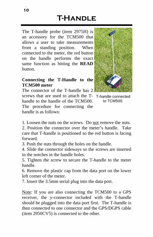
The T-handle probe (item 2975H) is an accessory for the TCM500 that allows a user to take measurements from a standing position. When connected to the meter, the red button on the handle performs the exact same function as hitting the READ button. Connecting the T-Handle to the TCM500 meter The connector of the T-handle has 2 screws that are used to attach the T-handle to the handle of the TCM500. The procedure for connecting the handle is as follows: 1. Loosen the nuts on the screws. Do not remove the nuts. 2. Position the connector over the meter’s handle. Take care that T-handle is positioned so the red button is facing forward. 3. Push the nuts through the holes on the handle. 4. Slide the connector sideways so the screws are inserted in the notches in the handle holes. 5. Tighten the screw to secure the T-handle to the meter handle. 6. Remove the plastic cap from the data port on the lower left corner of the meter. 7. Insert the 3.5mm serial plug into the data port. Note: If you are also connecting the TCM500 to a GPS receiver, the y-connector included with the T-handle should be plugged into the data port first. The T-handle is then connected to one connector and the GPS/DGPS cable (item 2950CV5) is connected to the other.
T-handle connected to TCM500.
11
Keypad Operation
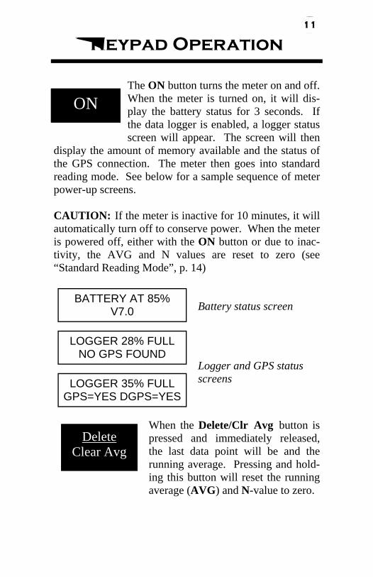
The ON button turns the meter on and off. When the meter is turned on, it will dis-play the battery status for 3 seconds. If the data logger is enabled, a logger status screen will appear. The screen will then
display the amount of memory available and the status of the GPS connection. The meter then goes into standard reading mode. See below for a sample sequence of meter power-up screens. CAUTION: If the meter is inactive for 10 minutes, it will automatically turn off to conserve power. When the meter is powered off, either with the ON button or due to inac-tivity, the AVG and N values are reset to zero (see “Standard Reading Mode”, p. 14)
ON
BATTERY AT 85% V7.0 Battery status screen
LOGGER 28% FULL NO GPS FOUND
LOGGER 35% FULL GPS=YES DGPS=YES
Logger and GPS status screens
When the Delete/Clr Avg button is pressed and immediately released, the last data point will be and the running average. Pressing and hold-ing this button will reset the running average (AVG) and N-value to zero.
Delete Clear Avg

12
Measurements are taken by pressing the READ button. The turf color data, in the currently selected mode (see be-low), will be displayed on the top line of the LCD.
The reading is also incorporated into the running average (AVG) and the sample number (N) is incremented. The current AVG and N are both displayed on the bottom line of the LCD. Up to 64 RED/NIR readings (N064) can be included in the running AVG. If more than 64 readings are taken before the data series is cleared or the meter is turned off, the AVG will not be updated. See “Standard Reading Mode” (p. 15) for more details.
Read
The MODE button selects which of three data formats will be displayed on the LCD. The mode can be changed after a measurement to view measure-ment values in different formats. The
TCM500 has three display modes; RED/NIR, NDVI, and Grass Index. See Meter Indexes (p. 20) NDVI The equation for NDVI computation is shown on p. 20. Grass Index The meter uses the reflectance values to compute a grass index (see p. 20) RED/NIR Displays the % reflectance in the RED (660 nm) and NIR (850 nm) wavelength bands.
MODE
RED/NIR = 17.1/ 60.5% N002 Av = 15.1/ 62.3%
NDVI = .462 N022 Av = .501
Grass Index=3.60 N010 Av=4.10

13
Adj. Grass Index From this screen, you can modify the default grass index to match your own evaluation of the turf. See “Adjusting the Grass Index”, (p. 21) for details on this procedure.
ADJ. GRASS INDEX Hit Del to Edit
14
Taking Readings
When in standard reading mode, the LCD of the TCM500 will display the turf color data and a running average. The average value remains in the meter’s short-term memory until it is deleted or the meter is shut off (see “Keypad Operation”, p. 11). If the data logger is enabled, the data is also recorded in the logger’s memory.
Do not take measurements when dew is present or when turf is wet following irrigation. Since moisture on turf affects the amount of reflected light from the samples, meter readings will not be accurate.
Readings will NOT be affected by ambient light (sun versus clouds) conditions. The TCM 500 has its own internal light source, allowing measurements to be made any time.
When measuring “taller” grass, it may be necessary to press down on the meter/sample such that ambient light is blocked out. Excessively bright ambient or reflected light will saturate the light sensors and thereby cause invalid readings. When the light sensors near the saturation point, an LCD message of !!ERROR!!, EXCESSIVE LIGHT will appear.
Meter Display
When in a measurement mode, the first line of the LCD will be the index reading in the currently selected mode (RED/NIR, NDVI, Grass) (see MODE button, p. 12). The second line gives information about the running average (AVG) and current sample number (N).
As each reading is taken, i.e. each time the trigger is released, the INDEX reading is incorporated into the
Standard Reading Mode
15
running average (AVG) and the sample number (N) is incremented. The current AVG and N are both displayed on the bottom line of the LCD.
Only a maximum of 64 INDEX readings (N064) can be used to generate the running AVG. If more than 64 readings are taken before the short-term memory is cleared, the AVG will remain at the value it had at N=64. However, deleting an INDEX reading from short-term memory (thus causing a new AVG to be calculated) does not free up memory space for storing an additional reading. In other words, the average is not calculated if the READ button has been pressed more than 64 times without clearing the average.
Valid index readings can be taken beyond the maximum N value of 64. But N will not continue to increment unless the entire current data series is cleared, resetting N to zero.
Logging Data
The data logger must be enabled in order to download data to a PC. In the Field Scout software, clicking a button entitled Meter Settings will display a screen that has Enable Meter’s Logging Function as an option. The box associated with this option must be checked in order to log and download data. Files downloaded from the TCM 500 meter are comma-delimited text files and can be opened in any word processing, spreadsheet, graphing, or statistical analysis program.
There are six columns in the downloaded text file. If GPS is used, longitude and latitude are in the first two columns. Otherwise, these 2 columns are empty. The sample number N, the %RED, %NIR, and NDVI are in the remaining columns (see “Data Files”, p. 19).
16
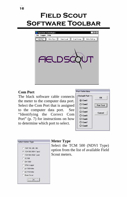
Com Port The black software cable connects the meter to the computer data port. Select the Com Port that is assigned to the computer data port. See “Identifying the Correct Com Port” (p. 7) for instructions on how to determine which port to select.
Meter Type Select the TCM 500 (NDVI Type) option from the list of available Field Scout meters.
Field Scout Software Toolbar

17
Download To download data from the internal data logger, turn the meter off and connect the gray serial cable to the RS-232 port beneath the ON button on the meter face plate. Click the Download button on the main software screen. In the Save Data As screen (see below), give the file a descrip-tive name and select the location where it will be saved. When the file has been saved, the software will give you the option of immediately viewing the file. The data file is stored as a comma-delimited text file and may be viewed in text editor or spreadsheet software.
Clear Memory The logger continuously adds to its memory until the logger is manually cleared by the Field Scout software. Data is not automatically removed from the logger mem-ory after a download. The Clear Memory button initiates the clear memory sequence. The software then warns you that you are about to clear the memory. Once you have cleared the logger memory, there is no way to retrieve the logged data from the meter.
Meter Settings Click this button to configure the meter and data logger. Refer to “Meter Settings” (p. 18) for more details.
18
Meter Settings
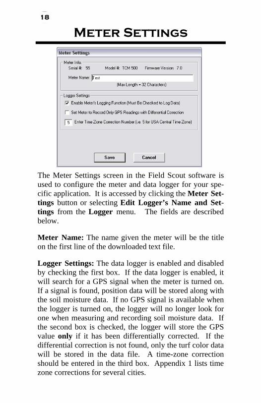
The Meter Settings screen in the Field Scout software is used to configure the meter and data logger for your spe-cific application. It is accessed by clicking the Meter Set-tings button or selecting Edit Logger’s Name and Set-tings from the Logger menu. The fields are described below. Meter Name: The name given the meter will be the title on the first line of the downloaded text file. Logger Settings: The data logger is enabled and disabled by checking the first box. If the data logger is enabled, it will search for a GPS signal when the meter is turned on. If a signal is found, position data will be stored along with the soil moisture data. If no GPS signal is available when the logger is turned on, the logger will no longer look for one when measuring and recording soil moisture data. If the second box is checked, the logger will store the GPS value only if it has been differentially corrected. If the differential correction is not found, only the soil moisture value will be stored in the data file. A time-zone correc-tion should be entered in the third box. Appendix 2 lists time zone corrections for several cities.
The Meter Settings screen in the Field Scout software is used to configure the meter and data logger for your spe-cific application. It is accessed by clicking the Meter Set-tings button or selecting Edit Logger’s Name and Set-tings from the Logger menu. The fields are described below. Meter Name: The name given the meter will be the title on the first line of the downloaded text file. Logger Settings: The data logger is enabled and disabled by checking the first box. If the data logger is enabled, it will search for a GPS signal when the meter is turned on. If a signal is found, position data will be stored along with the soil moisture data. If no GPS signal is available when the logger is turned on, the logger will no longer look for one when measuring and recording soil moisture data. If the second box is checked, the logger will store the GPS value only if it has been differentially corrected. If the differential correction is not found, only the turf color data will be stored in the data file. A time-zone correction should be entered in the third box. Appendix 1 lists time zone corrections for several cities.

19
The data is stored in comma-delimited text files. These files can be opened with text-editing software (e.g. Note-pad) or spreadsheet software (e.g. Excel). The first two lines of the data file give the logger’s name and serial number. The third line indicates that latitude and longitude are referenced to the 1984 World Geodetic Survey datum. The fourth line shows the column head-ings for the rest of the data file. Logging sessions are started and completed by turning the meter on and off. The start of a logging session is indi-cated by the data line “Logger Started.” If a GPS signal was found at the start of a logger session, a time stamp is included on the “Logger Started” line. The data file is separated into 6 fields: Latitude and Lon-gitude (blank if a GPS unit was not connected), sample number, Red reflectance, Near Infrared reflectance, and NDVI. The Grass Index is not saved in the data file.
Sample data showing results of data collected with and without GPS activated. Note: GPS signal not found when recording data in lines 10 through 15.
Data Files

20
Meter Indexes
The LCD of the TCM500 NDVI meter displays measurements in one of three modes (see MODE button p. 12). The modes are described below: 1.) Normalized Difference Vegetative Index (NDVI) NDVI is defined as:
NIR - Red
NDVI = ---------------- NIR + Red
Where: NDVI = Normalized Difference Vegetation Index NIR = Reflectance in the band of 850 + 5 nm Red = Reflectance in the band of 660 + 5 nm 2.) Grass Index (Factory Default) The Grass Index has a scale of 1 to 9 and approximates the rating a visual observer would assign to the turf grass. This provides a more objective value for this, generally, very subjective parameter. The Grass Index is calculated as follows: Grass Index = (NDVI X 6.6) + 2.26 Note: If the index has been manually adjusted (p. 21), the offset value is no longer 2.26. Rather, a new offset is calculated so the index value shown on the LCD matches the user’s evaluation of the turf’s color. 3.) Reflectance Values The percent of incident light of each wavelength band that is reflected back to the optical sensor in the meter. These same reflectance values are used to calculate NDVI and the Grass Index.
21
Adjusting the Grass Index
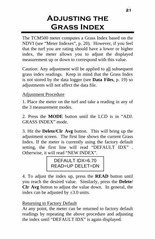
The TCM500 meter computes a Grass Index based on the NDVI (see “Meter Indexes”, p. 20). However, if you feel that the turf you are rating should have a lower or higher index, the meter allows you to adjust the displayed measurement up or down to correspond with this value.
Caution: Any adjustment will be applied to all subsequent grass index readings. Keep in mind that the Grass Index is not stored by the data logger (see Data Files, p. 19) so adjustments will not affect the data file.
Adjustment Procedure 1. Place the meter on the turf and take a reading in any of the 3 measurement modes.
2. Press the MODE button until the LCD is in “ADJ. GRASS INDEX” mode.
3. Hit the Delete/Clr Avg button. This will bring up the adjustment screen. The first line shows the current Grass Index. If the meter is currently using the factory default setting, the first line will read “DEFAULT IDX” . Otherwise, it will read “NEW INDEX”. 4. To adjust the index up, press the READ button until you reach the desired value. Similarly, press the Delete/Clr Avg button to adjust the value down. In general, the index can be adjusted by ±3.0 units. Returning to Factory Default At any point, the meter can be returned to factory default readings by repeating the above procedure and adjusting the index until “DEFAULT IDX” is again displayed.
DEFAULT IDX=6.70 READ=UP DELET=DN

22
Specifications
Measurement Sample: Turf grass canopy Measurement System: Reflectance of red (660 nm) and NIR (850 nm) light Light Requirements: The TCM 500 meter has its own internal light source. Measurement Area: Approximately 3.0 inches (7.6 cm) Measurement Units: a) Percent reflectance (0.0 to 99.9) of Red and NIR b) NDVI (0.000 to 1.000) c) Grass Index (1.00 to 9.00) Measurement Interval: One second per measurement without GPS Two to four seconds per measurement with GPS Repeatability: ± 5% of measurement Download File Format: Comma-delimited text file Temperature Range: 32° to 104° F (0° to 40°C) Environmental Sealing: Dust-proof Power Conservation: Automatically turns off after 10 minutes of inactivity Battery: 9 V Battery Approximately 3000 measurements Data Logger Capacity: 3250 measurements without GPS / DGPS 1350 measurements with GPS / DGPS

23
Error Messages
LIGHT LEAKAGE This error occurs when am-bient light leaks under to meter and on to the sample area.
MEMORY FULL This error occurs when the optional data logger capac-ity has been reached. Download the data and clear the memory.
LOW BATTERY This error message begins to flash when the alkaline battery level reaches 20%. Turn the meter off and re-place the batteries.
ABOVE CALIBRATION The optical sensor is out of calibration. Meter should be sent in for service. BELOW CALIBRATION
SENSOR SATURATION There may be damage to the internal light source. Meter should be sent in for service.

24
Appendix 1 Time zone corrections
Time Zone Correction
City
0 Dublin, Lisbon, London
3 Rio de Janeiro, Montevideo
4 Asuncion
5 USA: Eastern Standard Time
6 Central Standard Time
7 Mountain Standard Time
8 Pacific Standard Time
9 Anchorage
10 Honolulu
11 Wellington
13 Adelaide, Melbourne, Sydney
14 Vladivostok, Brisbane
15 Seoul, Tokyo
16 Beijing, Hong Kong, Manila, Singapore, Taipei
17 Hanoi, Jakarta, Vientiane
18 Calcutta, New Delhi
19 Kabul, Islamabad
20 Tehran, Abu Dhabi, Dubai
21 Moscow, Nairobi, Kampala, Riyadh
22 Ankara, Athens, Helsinki, Istanbul, Cairo, Johannesburg, Harare
23 Amsterdam, Barcelona, Berlin, Geneva, Paris, Prague, Rome, Brussels, Madrid, Stockholm, Warsaw, Lagos
25
Frequently Asked Questions
1. I am unable to bring up the Meter Settings screen. Generally, this indicates that the PC is not able to communicate with the meter. Check the following: - The interface cable is securely connected to both the PC and the meter - The meter has fresh batteries - The meter is off - The correct COM port is selected (see p. 7) - The Meter Type is set to the TDR family (see p. 16) 2. When turning the meter on, it indicated it had found the GPS signal. However, when taking readings I get a GPS error message. This can happen if the meter is set to only accept GPS readings that have been differentially corrected. In general, this is not necessary. On the Meter Settings screen (p. 18), uncheck the second box in the Logger Settings section.
3. My LCD is stuck at N = 65. 65 is the maximum number the LCD will display. At this point, additional readings can be made, but the index number (N value) will stay at 65. Press and hold the DELETE/CLR AVG button (p. 11) to return to normal operating mode.
4. I have new batteries. Why doesn’t my initial startup screen read “Battery at 100%”?
The battery strength indicator is set to accurately detect the strength of alkaline batteries. The displayed battery strength of NiCad batteries will be less than 100%.

26
Service and Support
The TCM 500 is easy to use and reliable. In the unlikely event that you have a problem with the hardware or software, please read the following.
Who do I contact?
Contact the company that you bought the TCM 500 meter from: Spectrum Technologies, Inc. or a Spectrum Authorized Dealer.
When Contacting Spectrum Technologies, Inc. Please indicate that you need Technical Support for the TCM 500 meter.
1. Write down the events that led to the problem. Have you changed anything in your computer recently? Are you doing anything differently?
2. Provide details on the hardware and software configuration of your computer including: manufacturer, model number, peripherals, and versions of the operating system.
3. Completely describe the problem. The more information you provide, the faster and more accurately we will be able to respond.
5. Does the TCM 500 transmit any light to the target?
Yes. The TCM 500 meter has an internal light source to illuminate the sample. It senses the light being reflected from the target.
27
Warranty
This product is warranted to be free from defects in material or workmanship for one year from the date of purchase. During the warranty period Spectrum will, at its option, either repair or replace products that prove to be defective. This warranty does not cover damage due to improper installation or use, lightning, negligence, accident, or unauthorized modifications, or to inci-dental or consequential damages beyond the Spectrum prod-uct. Before returning a failed unit, you must obtain a Returned Materials Authorization (RMA) from Spectrum. Spectrum is not responsible for any package that is returned without a valid RMA number or for the loss of the package by any shipping company.

28
DECLARATION OF CONFORMITY
Spectrum Technologies, Inc. 3600 Thayer Court
Plainfield, IL 60504 USA
Model Numbers: 2975NDVI Description: Turf Color Meter Type: Electrical Equipment for Measurement, Control, and Laboratory Use The undersigned hereby declares, on behalf of Spectrum Technologies, Inc. of Plainfield, Illinois, USA, that the above referenced product, to which this declaration relates, is in conformity with the provisions of:
Directive: 2004/108/EC Standards: EN 61326-1:2006 EN 61000-4-2:1995, including A1:1998 and A2:2001 EN 61000-4-3:2002 EN 55011:2007 Douglas L. Kieffer, Soil/Water Products Manager February 27, 2009
3600 Thayer Ct. Aurora, IL 60504
(800) 248-8873 or (815) 436-4440 Fax (815) 436-4460
E-Mail: [email protected] www.specmeters.com
Rev 12/13