model rem 500 neu tron sur vey meter - voss...
TRANSCRIPT
OPERATIONS AND REPAIR MANUAL
MODEL REM 500NEU TRON SUR VEY METER
IN CLUDES SEC TION ON MCA OP TION
Sep tem ber 1998 Re vi sion A
The REM-500 con tains a small check source. Please read the sec tion onRa dio ac tive ma te rial.
health phys ics in stru ments330 D South Kellogg Ave, Goleta, CA 93117 Tel 1-805-967-8422

TABLE OF CONTENTS
SPECIFICATIONS . . . . . . . . . . . . . . . . . . . . . . . . . . . . . . . . . ii
I. INTRODUCTION . . . . . . . . . . . . . . . . . . . . . . . . . . . . . . . . . 1
II. GETTING STARTED . . . . . . . . . . . . . . . . . . . . . . . . . . . . . . 1
III. MODES OF OPERATION. . . . . . . . . . . . . . . . . . . . . . . . . . . . 2
IV. CHANGE MODE . . . . . . . . . . . . . . . . . . . . . . . . . . . . . . . . 3
V. BUTTONS . . . . . . . . . . . . . . . . . . . . . . . . . . . . . . . . . . . . 5
VI. OVERFLOW, AND HIGH RADIATION LEVELS . . . . . . . . . . . . . . 6
VII. SHOCK . . . . . . . . . . . . . . . . . . . . . . . . . . . . . . . . . . . . . 7
VIII. LOW BATTERY . . . . . . . . . . . . . . . . . . . . . . . . . . . . . . . . 7
IX. BATTERY REPLACEMENT . . . . . . . . . . . . . . . . . . . . . . . . . . 7
X. FAILURE . . . . . . . . . . . . . . . . . . . . . . . . . . . . . . . . . . . . . 8
XI. STATISTICS AND COUNTS . . . . . . . . . . . . . . . . . . . . . . . . . . 8
XII. CHECK MODE. . . . . . . . . . . . . . . . . . . . . . . . . . . . . . . . . 8
XIII. MULTICHANNEL ANALYZER MODE. . . . . . . . . . . . . . . . . . . 9
XIV. SERIAL COMMUNICATIONS . . . . . . . . . . . . . . . . . . . . . . . 10
XV. PRINCIPAL OF OPERATION . . . . . . . . . . . . . . . . . . . . . . . . 11
1. ELEC TRONICS/SOFT WARE. . . . . . . . . . . . . . . . 11
2. DE TEC TOR . . . . . . . . . . . . . . . . . . . . . . . . . 12
XVI. CALIBRATION MODE . . . . . . . . . . . . . . . . . . . . . . . . . . . 13
XVII. CALIBRATING THE INSTRUMENT . . . . . . . . . . . . . . . . . . . 16
XVIII. RADIOACTIVE MATERIAL INSIDE DETECTOR . . . . . . . . . . . 18
XIX. MAINTENANCE MODE . . . . . . . . . . . . . . . . . . . . . . . . . . 19
XX. CIRCUIT DESCRIPTION . . . . . . . . . . . . . . . . . . . . . . . . . . 20
XXI. ELECTRONIC ADJUSTMENTS . . . . . . . . . . . . . . . . . . . . . . 23
XXII. TROUBLE SHOOTING NOTES . . . . . . . . . . . . . . . . . . . . . . 25
XXIII. QUALITY FACTORS . . . . . . . . . . . . . . . . . . . . . . . . . . . 26
XXIV. PARTS LIST . . . . . . . . . . . . . . . . . . . . . . . . . . . . . . . . 27
XXV. PARTS LOCATION AND SCHEMATICS . . . . . . . . . . . . . . . . 31
REM 500 INSTRUCTION MANUAL i

SPECIFICATIONS
MECHANICAL Size: 12"L x 4.5"W x 4.5"H ex clud ing han dle, han dle ex tends height to 6.25".
Weight: 5 lbs, 2 oz in clud ing al ka line bat ter ies.
Ex ter nal Con trols: 5 pushbutton switches for POWER ON/OFF, MODE, AL -TER NATE, RE SET and LIGHT.
In ter nal Con trols: Cal and Re set pushbutton;Coarse Con trast, Pole Zero, HighVolt age, and LLD trimpots.
DETECTOR Type: Sealed Spher i cal TE Pro por tional Coun ter. Rossi Type. 2 1/4" ID.
Wall Ma te rial: A150 Con ducting Tis sue Equiv a lent plas tic.
Wall Thick ness: 0.12 cm, 144 mg/cm, Alu mi num can .065"
Fill ing Gas: Pro pane gas, 2 mi cron
In ter nal Source: Less than 1 uCi Cm244
OPERATIONAL Read out: Al pha nu meric 2 line x 16 char ac ter LCD
Range: Autoranging from .001 mREM/h to 999 REM/h and .001 mRAD/h to 999RAD/h rate and .001 mREM to 999 REM and .001 mRAD to 999 RAD in te grate.SI units of Sv and Gy are also selectable.
Multi-Channel An a lyzer: 256 Chan nel MCA. 65535 counts/chan nel. RS-232 se -rial link can con trol MCA op er a tion.
Tem per a ture De pend ence: less than ± 15 % from 15 to 45°C
Hu mid ity Re sponse: Less than 10 % change from 0 to 95 % RH non con dens ing.
Neu tron En ergy Re sponse: 70 KeV to 20 MeV
Gamma Re sponse: Less than 1% at 1 RAD/h.
Warm Up Time: 15 sec onds
Bat tery Life: 100 hours; 6 ea al ka line C cells.
Se rial RS232 link: In Rate and In te grate mode, sends ra di a tion level on com -mand. In MCA mode dumps MCA raw chan nel data, count time, to tal counts andIn stru ment Cal i bra tion Fac tor. Baud rate is 9600. Avail able if the MCA op tion isin stalled.
REM 500 INSTRUCTION MANUAL ii

PLEASE NOTE:
All of the de scrip tions and ex am ples through out the man ual use the units of Remand Rad. Si units of Sv and Gy are also avail able. To se lect the Si units please re -fer to the Cal i bra tion sec tion.
This man ual cov ers the REM-500 with or with out the MCA op tion. To check ifthe MCA op tion is in stalled, look on the front panel. If the panel con tains a jackon the lower right for a con nec tor, then the MCA op tion has been in stalled.
REM 500 INSTRUCTION MANUAL iii
I. INTRODUCTION
The Rem 500 is a Neu tron Sur vey Me ter that reads in both REM and RADS. It is a small light por ta ble in stru ment that is at home both in the field and in the lab. Thisman ual de scribes its op er a tion and use.
II. GETTING STARTED
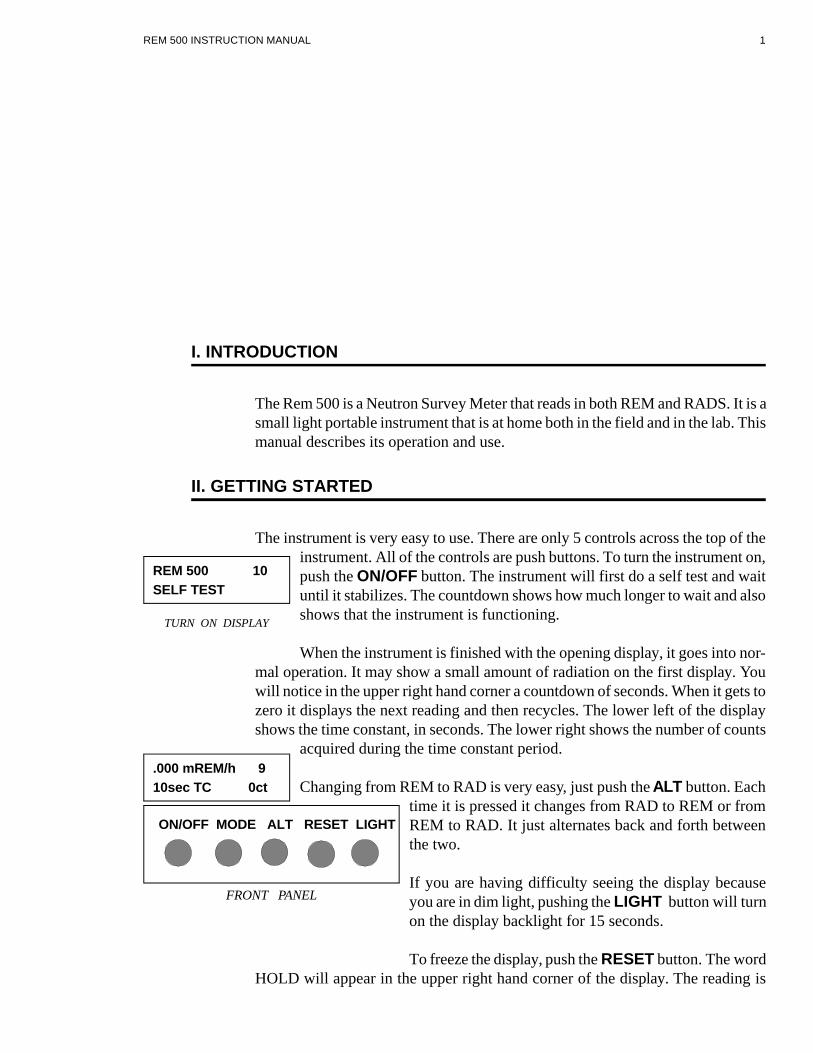
The in stru ment is very easy to use. There are only 5 con trols across the top of thein stru ment. All of the con trols are push but tons. To turn the in stru ment on,push the ON/OFF but ton. The in stru ment will first do a self test and waitun til it sta bi lizes. The count down shows how much lon ger to wait and alsoshows that the in stru ment is func tion ing.
When the in stru ment is fin ished with the open ing dis play, it goes into nor -mal op er a tion. It may show a small amount of ra di a tion on the first dis play. Youwill no tice in the up per right hand cor ner a count down of sec onds. When it gets tozero it dis plays the next read ing and then re cy cles. The lower left of the dis playshows the time con stant, in sec onds. The lower right shows the num ber of counts
ac quired dur ing the time con stant pe riod.
Changing from REM to RAD is very easy, just push the ALT but ton. Eachtime it is pressed it changes from RAD to REM or fromREM to RAD. It just al ter nates back and forth be tweenthe two.
If you are hav ing dif fi culty see ing the dis play be causeyou are in dim light, push ing the LIGHT but ton will turn on the dis play backlight for 15 sec onds.
To freeze the dis play, push the RE SET but ton. The word HOLD will ap pear in the up per right hand cor ner of the dis play. The read ing is
REM 500 INSTRUCTION MANUAL 1
.000 mREM/h 910sec TC 0ct
REM 500 10SELF TEST
TURN ON DISPLAY
ON/OFF MODE ALT RESET LIGHT
FRONT PANEL

now frozen. Pushing the RE SET but ton again will re set the in stru ment and put itback into nor mal op er a tion.
To change from the rate mode of op er a tion, to the in te grate mode, just push theMODE but ton twice. To get back to the RATE mode, again push the MODE but -ton twice. Switching back and forth be tween rate and in te grate is very easy, just
push the MODE but ton twice.
The in te grate mode has a slightly dif fer ent dis play. TheIn te grate time is shown on the lower left. The counts thathave been ac quired re main on the lower right. The up perright is blank. The ALT, RE SET, and LIGHT but tonswork in this mode just like the rate mode.
You have now run the in stru ment through its ba sic op er a tion. More ar eas of thein stru ment are dis cussed in the fol low ing sec tions. Re mem ber you can not hurtthe in stru ment if you push the wrong but ton at the wrong time. Turn ing it on andoff will re store it to nor mal op er a tion.
III. MODES OF OPERATION
There are three main modes of op er a tion, rate, in te grate, and Mul ti chan nel An a -lyzer (if in stalled). Rate and in te grate are dis cussed here. See the Mul ti chan nelAn a lyzer sec tion for a de scrip tion of that mode. In ad di tion there is a Check mode which is dis cussed in the Check Mode sec tion. Each mode can be iden ti fied by the ar range ment of the dis play. See the MCA mode sec tion for a de scrip tion of theMul ti chan nel An a lyzer.
RATE MODE
Fig ure 1 shows the RATE dis play. When first turned on, the in stru ments is in thismode. The in te grate mode can be reached by push ing MODE twice fromthe Rate mode.
The ra di a tion level, autoranging from .001 mREM/h to 999 REM/h, isshown on the up per left. If the in stru ment is read ing RADS, then it willshow be tween .001 mRAD/h and 999 RAD/h. It in di cates over range byshow ing >1K REM/h (or >1K RAD/h if read ing in RADS) in the dis play.
The lower left shows the cur rent time con stant. The in stru ment gath ers data forthe time con stant pe riod then dis plays it. The up per right hand cor ner of the dis -play shows the time re main ing in this pe riod. There are 3 Time Con stant set tings;10, 30, or 60 sec onds. The num ber in the up per right cor ner of the dis play showsthe time re main ing in this time con stant pe riod. Each read ing is com pletely sep a -rate from any other read ing.
The lower right hand cor ner shows the num ber of events that have been counteddur ing this pe riod. When the HOLD but ton is pushed the word HOLD will ap -
REM 500 INSTRUCTION MANUAL 2
ON/OFF MODE ALT RESET LIGHT
FRONT PANEL
.000 mREM/h 9
10sec TC 0ct
FIGURE # 1RATE DISPLAY

pear in the up per right cor ner of the dis play. If the bat tery is bad, the word LBATwill flash in the same place.
IN TE GRATE MODE
Fig ure 2 shows the In te grate dis play. The In te grate dis play can be reached bypush ing MODE twice from the RATE dis play. The dis play is up dated ev -ery 10 sec onds. The ra di a tion level, autoranging from .001 mREM to 999REM, is shown on the up per left. If the in stru ment is read ing RADS, thenit will show be tween .001 mRAD and 999 RAD. It in di cates over range byshow ing 1K REM (or 1K RAD if read ing in RADS) in the dis play.
The lower left shows the time of in te gra tion. It dis plays the time inHRS:MIN:SEC and will go as high as 18 hrs, 12 min and 15 sec onds be fore it re -sets to zero. It up dates ev ery sec ond. The lower right hand cor ner shows the num -ber of events that have been counted. When the HOLD but ton is pushed, thein stru ment re cal cu lates the level for that sec ond then up dates the dis play andshows HOLD in the up per right hand cor ner. Switching be tween REM and RAD,when on hold, us ing the ALT but ton, will show the two lev els. If the bat tery isbad, the word LBAT will flash in the up per right hand cor ner.
The in stru ment will con tinue to gather data un til it is re set.
IV. CHANGE MODE
The change mode al lows ad just ment of the dis play con trast and time con stant; itis also a way into the Check mode.
There are five lev els of dis plays that can be shown be sides the rate and in te gratedis plays. We have named them level 1, level 2, level 3, check and MCA. You mayhave no ticed level 1 when you switched be tween the rate and in te grate modes. On these dis plays the mean ing of the keys are changed. The new mean ing is shownon the dis play with ar rows point ing to the cor re spond ing key. The keys that are re -de fined in all ex cept the MCA mode are the three mid dle keys. The LIGHT keyis not changed ex cept in the MCA mode. The ON/OFF key is not changed.
The five lev els are shown be low. To get to level 1 push the MODE key once. Toget to level 2 just push the ↓NEXT key. To get to level 3 just push the ↓NEXT keyagain, and to get back to nor mal op er a tion, just push the ↓NEXT key again. Ifyou are in the Check dis play, push ing ↓NEXT will get you back to nor mal op er a -tion. The same is also true for the MCA mode. Pushing the ↓NEXT key re peat -edly will al ways get you back to nor mal op er a tion.
REM 500 INSTRUCTION MANUAL 3
↓NEXT
Soft Keys areshown with an
arrow.
.000 mREM
00:00:10 0ct
FIGURE # 2INTEGRATE DISPLAY

LEVEL 1 MENU
This is the dis play for the Level 1 menu if the in stru ment was in the In te -grate mode when the MODE but ton was pushed. You will note that thenew def i ni tion of the MODE but ton is RATE. If the in stru ment was in theRATE mode when the MODE but ton was pushed, then the dis play wouldlook like the next ex am ple. This change of def i ni tion of the key is the way
it is pos si ble to switch be tween the Rate and In te grate mode just by push ing themode but ton twice. To exit this menu push ei ther the INT or RATE and you willbe back in nor mal op er a tion. ↓NEXT moves you to the next dis play as shown be -low.
LEVEL 2 MENU
This is the dis play for the LEVEL 2 MENU. It al lows ad just ment of two items,the Time Con stant or TC and the dis play con trast. Pushing the but tons un -der each one changes the cor re spond ing item. For ex am ple, push ing the↓TC but ton would change the TC from 10 to 30. Pushing the ↓DISPL but -ton would change the con trast 1 level. ↓NEXT moves you to the next dis -
play as shown be low.
LEVEL 3 MENU
This is the Check menu that only al lows you to go into the check or MCA mode.Pushing the ↓CHECK but ton changes into the Check menu. Pushing the↓MCA but ton (if in stalled) changes into the MCA menu. The ↓NEXTbut ton re turns you to nor mal op er a tion.
CHECK MENU
This is the Check menu. The num bers un der the LFT, PK and RT will becal cu lated, the num bers shown are just for ref er ence. See the Check sec -tion for an ex pla na tion of Check. ↓NEXT re turns you to nor mal op er a -tion. A de tailed dis cus sion of the func tion of each key is dis cussed in theBut tons sec tion.
MCA MENU
This is the Mul ti chan nel or MCA menu. This mode al lows the in stru mentto gather data and then down load the data to a com puter on an RS232 se rial link.The re mote com puter can also con trol the op er a tion of the MCA. See the MCAsec tion for a com plete ex pla na tion of the MCA. ↓NEXT re turns you to nor malop er a tion.
REM 500 INSTRUCTION MANUAL 4
INT RATE NEXT
00:00:00 0CT
TC DISPL NEXT
10↓ ↓ ↓
CHECK MCA NEXT
↓ ↓ ↓
MCA will show only if theMCA option is installed.
LFT PK RT NEXT
080 090 100 ↓
RATE INT NEXT
↓ ↓ ↓

V. BUTTONS
There are 5 but tons on the front of the in stru ment. There op er a tion is de scribedbe low.
ON/OFF Turns the in stru ment on and off. If the in stru ment is on, push ing it willturn it off. If it is off, push ing it will turn it on.
MODE Se lects the var i ous modes and dis plays. Pushing it twice will switch be -tween rate and in te grate and vice a versa. Pushing it once will en ter the menu ofLevel 1.
ALT ALT is for AL TER NATE which se lects be tween REM and RAD. If the in -stru ment is read ing in REM push ing the ALT will switchto RAD. If the in stru ment is read ing in RAD, push ing itwill change to REM. When in the Rate mode, switch ingbe tween REM and RAD will re set the data even if the in -stru ment is on hold. This is not true for the In te graterange. If the in stru ment is on hold, then switch ing be -tween RAD and REM will not re set the data.
RE SET Puts the in stru ment in ei ther a Hold mode, or re sets it. The first push ofthe but ton holds the data. The dis play will show HOLD in the up per right handcor ner to let you know that the in stru ment is in hold. Pushing the but ton again will re set the in stru ment and it will re sume nor mal op er a tion. If the in stru ment is onHOLD and in the in te grate range, the ALT but ton will change be tween RAD andREM on the same data with out re set ting the in stru ment.
LIGHT Turns on the light for 16 sec onds. If you are in the var i ous menu’s, push -ing the light will keep it on un til you go back to nor mal op er a tion.
NOTE: To reach LEVEL 1 from nor mal op er a tion push MODE.
LEVEL 1 ↓INT Puts the in stru ment into the In te grate mode.
LEVEL 1 ↓RATE Puts the in stru ment into the Rate mode.
LEVEL 1↓NEXT Changes from level 1 to level 2
NOTE: To reach LEVEL 2 from nor mal op er a tion push MODE, ↓NEXT.
LEVEL 2 ↓TC Changes the Time con stant of the in stru ment for the Rate mode.Each time it is pressed it changes to the next time con stant. There are three timecon stants, 10, 30 and 60 sec onds. This is the time the in stru ment will gather databe fore pre sent ing it on the screen. The up per right hand cor ner of the rate dis playwill show the time re main ing in this time con stant, i.e. be fore up dat ing. The in -stru ment will re mem ber the time con stant when it is turned off. The next time it is
REM 500 INSTRUCTION MANUAL 5
ON/OFF MODE ALT RESET LIGHT
FRONT PANEL
turned on it will have the same time con stant. If it is set to 60 sec onds and turnedoff, the next time it is turned on it will still be 60 sec onds.
LEVEL 2 ↓DISPL Changes the con trast of the dis play. There are 12 lev els ofcon trast. Each push of the ↓DISPL but ton will change the con trast by one level.When the con trast reaches the max i mum it jumps to the min i mum. Just keeppush ing the but ton un til the con trast looks cor rect. When the in stru ment is turnedoff, it re mem bers the con trast set ting.
LEVEL 2 ↓NEXT Changes from level 2 to level 3
NOTE: To reach LEVEL 3 from nor mal op er a tion push MODE, ↓NEXT,↓NEXT.
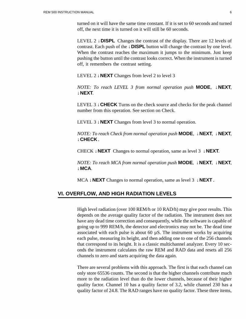
LEVEL 3 ↓CHECK Turns on the check source and checks for the peak chan nelnum ber from this op er a tion. See sec tion on Check.
LEVEL 3 ↓NEXT Changes from level 3 to nor mal op er a tion.
NOTE: To reach Check from nor mal op er a tion push MODE, ↓NEXT, ↓NEXT,↓CHECK.
CHECK ↓NEXT Changes to nor mal op er a tion, same as level 3 ↓NEXT.
NOTE: To reach MCA from nor mal op er a tion push MODE, ↓NEXT, ↓NEXT,↓MCA.
MCA ↓NEXT Changes to nor mal op er a tion, same as level 3 ↓NEXT.
VI. OVERFLOW, AND HIGH RADIATION LEVELS
High level ra di a tion (over 100 REM/h or 10 RAD/h) may give poor re sults. Thisde pends on the av er age qual ity fac tor of the ra di a tion. The in stru ment does nothave any dead time cor rec tion and con se quently, while the soft ware is ca pa ble ofgo ing up to 999 REM/h, the de tec tor and elec tron ics may not be. The dead timeas so ci ated with each pulse is about 60 µS. The in stru ment works by ac quir ingeach pulse, mea sur ing its height, and then add ing one to one of the 256 chan nelsthat cor re spond to its height. It is a clas sic mul ti chan nel an a lyzer. Ev ery 10 sec -onds the in stru ment cal cu lates the raw REM and RAD data and re sets all 256chan nels to zero and starts ac quir ing the data again.
There are sev eral prob lems with this ap proach. The first is that each chan nel canonly store 65536 counts. The sec ond is that the higher chan nels con trib ute muchmore to the ra di a tion level than do the lower chan nels, be cause of their higherqual ity fac tor. Chan nel 10 has a qual ity fac tor of 3.2, while chan nel 230 has aqual ity fac tor of 24.8. The RAD ranges have no qual ity fac tor. These three items,
REM 500 INSTRUCTION MANUAL 6

dead time, max i mum counts/chan nel, and dif fer ent qual ity fac tors lead us to sev -eral guide lines:
1. At 10,000 counts in 10 sec onds, the in stru ment will loose 1% of the counts andre sponse will start to fall off above this amount.
3. If the REM/h range is overrange, then sus pect the RAD/h range has dead timelosses.
4. If you have to use the in stru ment in high ra di a tion lev els, then cor rect for deadtime losses.
VII. SHOCK
The in stru ment has some sen si tiv ity to shock. Banging the case or the de tec torcould re sult in spu ri ous counts. A sharp rap on the de tec tor with a pen cil will in -deed pro duce spu ri ous counts. Just hold the in stru ment with the han dle and don’tbang it against any thing while mak ing mea sure ments.
VIII. LOW BATTERY
When first turned on the in stru ment turns on the light and checks the sta tus of thebat tery. If it has less than 10 hours re main ing, it will show LOW BAT TERY in the dis play. If the bat ter ies are too poor to turn the in stru ment on the dis play will re -main dim.
Dur ing nor mal op er a tion the in stru ment con tin u ally checks the sta tus of the bat -ter ies. If it sees that there are only 10 hours re main ing, then the in stru ment willflash LBAT in the up per right hand cor ner of the dis play ev ery 13 sec onds. This isonly in the RATE and IN TE GRATE modes, it will not show low bat tery inLEVEL 1, 2, 3 or CHECK. In the MCA mode the up per right cor ner will flashwhen the bat ter ies are low.
The light uses the most power. If the bat ter ies just check good, turn ing on the light may make them check bad. This is the rea son the in stru ment, when first turned on, checks the bat ter ies with the light on. When the bat ter ies are low it is a good ideanot to use the light.
IX. BATTERY REPLACEMENT
The Rem 500 uses 6 C cells, ei ther car bon zinc or al ka line. The al ka line will ofcourse last lon ger. The cur rent drain is less than 40 mA with the light off.
To change the bat ter ies re move the four screws on the end of the case that hold onthe small cover. The bat ter ies should fall out. Use the sticker on the in side of the
REM 500 INSTRUCTION MANUAL 7

box as a guide line for in sert ing them. The bat ter ies on the left hand side go in capsfirst, and those on the right go in with their caps out. Do not ship the in stru mentwith bat ter ies be cause it may turn on in ship ment.
X. FAILURE
The in stru ment self checks it self at turn on. If it de tects a fail ure it will dis playFAIL URE in the dis play. If this oc curs the in stru ment can not be used. See theMain te nance Mode sec tion for re pair pro ce dures.
XI. STATISTICS AND COUNTS
The dis play shows the num ber of counts that the in stru ment has re ceived for thatread ing in the lower right hand cor ner. For valid sta tis tics the num ber of counts isim por tant. To achieve a rea son able ac cu rate read ing the num ber of counts needsto be at least 10. It should pref er a bly be around 100 and for more ac cu rate anal y sis it should be around 1000. This is the rea son for the dif fer ent time con stants. Inhigh ra di a tion ar eas the time con stant may be any set ting but the lower TC of 10sec would prob a bly be suf fi cient if the counts are high enough. Ob vi ously as thera di a tion level de creases the time con stant should be in creased to 30 or 60 sec -onds to give more time to ac cu mu late counts to ob tain better sta tis tics. The in te -grate range can be used for any ra di a tion level but it is re ally ideal when look ing at very low lev els.
XII. CHECK MODE
The Check mode of op er a tion is used to de ter mine the qual ity of the de tec tor, andto check the op er a tion of the in stru ment. It can be used as an op er a tional check. To get in to the Check mode from nor mal op er a tion push MODE, ↓NEXT, ↓NEXT,↓CHECK.
In side the de tec tor is a small Cu rium al pha source. When in the Checkmode the cu rium source ra di ates a small stream of alphas across the cen terof the de tec tor. These events sim u late a neu tron event in chan nel 90 of thein stru ment.
In the Check mode, the in stru ment op er ates as a mul ti chan nel an a lyzer and dis -plays the peak (PK) chan nel num ber as well as the left (LFT) and right (RT) halfmax chan nel num bers. It up dates the dis play ev ery sec ond. Pushing the ALT but -ton will re set the MCA data and re start the ac qui si tion. If the dis play re mains onchan nel 0 or 1 this in di cates that the in stru ment is not func tion ing prop erly. Trytap ping on the side of the de tec tor to free the shut ter that shields the al pha source.
The peak chan nel in di cates the cal i bra tion of the in stru ment, and the left and righthalf max chan nels in di cate the qual ity of the de tec tor. The peak should be within
REM 500 INSTRUCTION MANUAL 8
LFT PK RT NEXT
080 090 100 ↓
15 chan nels of 90. Each chan nel away from 90 is an er ror of about 1.5% if the Cal -i bra tion Fac tor re mains un changed. If it is out of this range, then the high volt ageneeds to be ad justed as de scribed in the Cal i bra tion Mode sec tion VI. The spreadof the chan nels (RIGHT-LEFT) should be no more than 50 chan nels. If the spread is more than this then the de tec tor needs to be re turned to the fac tory for re fill ing.
Leave this mode by push ing ↓NEXT. If the rate dis play reads a high num ber af terleav ing Check mode, then the mag net ac tu ated shut ter that shields the al phasource may be stuck. Just tap ping the side of the de tec tor should free the shut ter.
There is also an ad di tional Check mode in the Mul ti chan nel An a lyzer sec tion thatal lows dump ing all the chan nels. See that sec tion for a de scrip tion of the Checkmode.
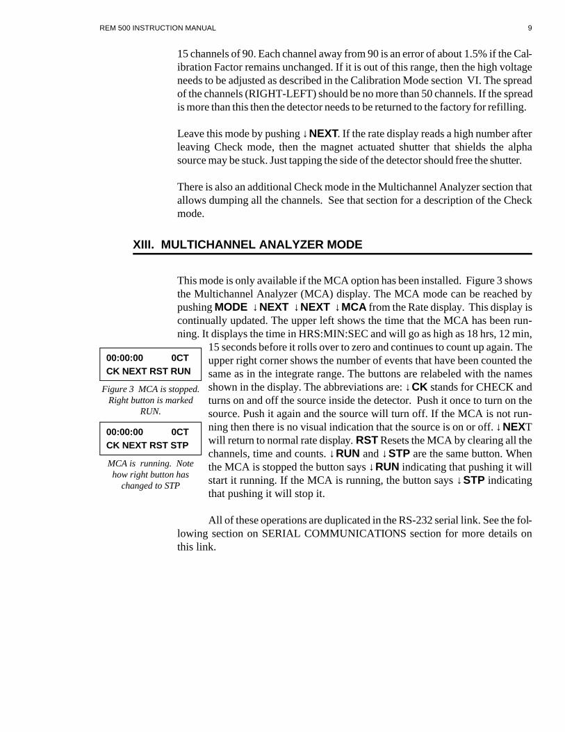
XIII. MULTICHANNEL ANALYZER MODE
This mode is only avail able if the MCA op tion has been in stalled. Fig ure 3 showsthe Mul ti chan nel An a lyzer (MCA) dis play. The MCA mode can be reached bypush ing MODE ↓NEXT ↓NEXT ↓MCA from the Rate dis play. This dis play is con tin u ally up dated. The up per left shows the time that the MCA has been run -ning. It dis plays the time in HRS:MIN:SEC and will go as high as 18 hrs, 12 min,
15 sec onds be fore it rolls over to zero and con tin ues to count up again. The up per right cor ner shows the num ber of events that have been counted thesame as in the in te grate range. The but tons are relabeled with the namesshown in the dis play. The ab bre vi a tions are: ↓CK stands for CHECK andturns on and off the source in side the de tec tor. Push it once to turn on thesource. Push it again and the source will turn off. If the MCA is not run -ning then there is no vi sual in di ca tion that the source is on or off. ↓NEXTwill re turn to nor mal rate dis play. RST Re sets the MCA by clear ing all thechan nels, time and counts. ↓RUN and ↓STP are the same but ton. Whenthe MCA is stopped the but ton says ↓RUN in di cat ing that push ing it willstart it run ning. If the MCA is run ning, the but ton says ↓STP in di cat ingthat push ing it will stop it.
All of these op er a tions are du pli cated in the RS-232 se rial link. See the fol -low ing sec tion on SE RIAL COM MU NI CA TIONS sec tion for more de tails onthis link.
REM 500 INSTRUCTION MANUAL 9
00:00:00 0CTCK NEXT RST RUN
Figure 3 MCA is stopped. Right button is marked
RUN.
00:00:00 0CTCK NEXT RST STP
MCA is running. Notehow right button has
changed to STP
XIV. SERIAL COMMUNICATIONS
There is an RS-232 Se rial link built into the REM-500 for com mu ni ca tions with ater mi nal or com puter. It is only avail able if the MCA mode is in stalled. The linknot only al lows the user re mote con trol of the MCA but also dumps the data oncom mand. One end of the RS-232 Ca ble plugs into the top of the REM-500 nextto the han dle. The other end plugs into the 25 pin RS-232 COM port of a Per sonalCom puter or a ter mi nal. The com puter or ter mi nal should be set to: 9600 baud, no par ity, 8 data bits, 1 stop bit. The se rial link al lows com mu ni ca tions with both thenor mal rate and in te grate dis plays and with the MCA. When the in stru ment is inthe nor mal rate or in te grate mode send ing a T to the REM-500 will turn on thedata link. The in stru ment will re spond with an * and will send out the ra di a tionlevel ev ery time it up dates the dis play. The level is the same as the dis play. This isev ery 10 sec onds in the in te grate mode, and when the time reaches 0 in the ratedis play. To turn it off, turn the in stru ment off. The data that is trans mit ted is 5 dig -its of ra di a tion level fol lowed by an ex po nent. The ba sic units are uREM, uRAD,uREM/h and uRAD/h or nSv, nGy, nSv/h and nGy/h de pend ing on the mode thein stru ment is in and are the same as the dis play. The ex po nent is the power of 10that the read ing should be mul ti plied by. Thus 12567 0 would be 12567 x 10E0which is 12567 uREM/h or 12.567 mREM/h and 67785 3 would be 67785 x 10E3which is 67785 x 1000 which is 67785000 uREM/h which is 67.785 REM/h if thein stru ment was in the rate mode read ing REM.
In the MCA mode the se rial link al lows com plete con trol of the MCA. The in stru -ment must be in the MCA mode for this link to func tion. The com mands are sin -gle char ac ters ex cept for the D com mand and are as fol lows:
R RE SET This will re set the MCA and all data, time and chan nels. This is thesame as push ing the RST but ton.
S STOP This will stop the MCA. This is the same as push ing the STP but ton.
G GO This will start the MCA. This is the same as push ing the RUN but ton.
C CHECK This will turn on the check source in the de tec tor if the source is off,and turn it off if it is on. This is the same as push ing the CK but ton.
D This will dump the chan nel data on the se rial port. A char ac ter is needed af terthe D to ac tu ally send the data, i.e. it needs two char ac ters to dump the data, a Dfol lowed by any char ac ter. The in stru ment au to mat i cally stops be fore dump ingthe data.
In ad di tion, when the in stru ment is run ning in MCA mode, it will send the fol low -ing line ev ery sec ond: 6 hex dig its of counts fol lowed by the time inHR:MIN:SEC. These val ues are the same val ues as shown on the dis play ex ceptthe counts are in hex.
REM 500 INSTRUCTION MANUAL 10

DATA DUMP OF CHAN NELS
Sending a D fol lowed by an other char ac ter when the in stru ment is in the MCAmode will dump the data from the chan nels. The Data re cord is as fol lows:
256 lines of 5 dig its. This is the counts for each chan nel. The counts are from 0 to65534. 65535 is the max i mum count even if the counts are more than this. Thereis no over flow in di ca tion other that keep ing the count at the max i mum value. The next is a line of counts and time. The counts are in HEX and are the to tal counts ofall chan nels. This is 6 hex dig its. The time is in HR:MIN:SEC. This line is thesame as sent ev ery sec ond when the MCA is run ning.
XV. PRINCIPAL OF OPERATION
The In stru ment is ba si cally a 256 chan nel mul ti chan nel an a lyzer or MCA with aded i cated pro gram cou pled to a Tis sue Equiv a lent Rossi type spher i cal pro por -tional coun ter.
1. ELEC TRONICS/SOFT WARE
In nor mal op er a tion the in stru ment gath ers the pulses from the de tec tor, mea surestheir height, counts them and stores them ac cord ing to their height, and then cal -cu lates the cor rect REM or RAD. Ev ery 10 sec onds it goes through this rou tine,and ev ery 10 sec ond in ter val is sep a rate. In the rate mode it uses 1, 3, or 6 (de -pend ing on the TC) of these 10 sec ond in ter vals for the to tal value. In the in te grate mode it just sums the re sults of each 10 sec ond cal cu la tion. Thus ev ery 10 sec ondop er a tion is the same re gard less of the mode or the time con stant.
The dis play is de rived from the for mu las:
For a 10 sec ond in te gra tion pe riod, where TC = 1 for 10 sec, 3 to 30 sec, 6 for 60sec and 360 for in te grate.
REM KCHAN CNTS per chan QF
TC= ×
× ××∑
5
255
256
#
.
RAD KCHAN CNTS per chan
TC= ×
××∑
5
255
256
#
.
The QF for the chan nels is de rived from a smooth ing of the ICRP val ues andranges from 1 to 24.8. K is the Cal i bra tion Fac tor. If you wish a dif fer ent QF thenplease con sult HPI. The RAD dis play is thus the same as the REM ex cept for theQual ity fac tors. The av er age qual ity fac tor can be de rived by di vid ing the REMread ing by the RAD read ing.
REM 500 INSTRUCTION MANUAL 11

2. DE TEC TOR
The de tec tor is a spher i cal tis sue equiv a lent pro por tional coun ter which mea suresthe ab sorbed dose in LET (ac tu ally P[Y]) spec tra. It is based upon the de sign orig -i nated by Rossi us ing a spi ral grid over the elec trode for uni form col lec tion char -ac ter is tics.
The de tec tor is housed in an alu mi num shell which serves as a vac uum tight hous -ing. The hous ing is filled with pro pane gas which al lows the spher i cal de tec tor tosim u late small tis sue vol umes of ap prox i mately 2 mi cron di am e ter.
An in ter nal Cm244 al pha source is mounted to al low the al pha par ti cles to tra -verse the di am e ter of the sphere in the CHECK mode. The en ergy de pos ited bythe al pha par ti cle is con sid ered to be 90 KeV/µ. There fore by ad just ing the sys tem to place the peak into chan nel 90, the pulse height of the in ter ac tions will cor re -spond to the en ergy de po si tion in KeV/µ.
When the in stru ment is placed in a neu tron field, the in ter ac tions with the neu -trons will cause a re coil pro ton to tra verse a por tion of the sphere. The neu troncol lides with a nu cleus and is scat tered with a loss of en ergy which ap pears as theki netic en ergy of the re coil nu cleus. In tis sue, elas tic scat ter ing is the dom i nantneu tron in ter ac tion in the en ergy in ter val 10 KeV to 10 MeV i.e. the sum of the ki -netic en er gies of the par tic i pat ing par ti cles re mains con stant be fore and af ter thein ter ac tion. The av er age neu tron en ergy loss will be one half for a col li sion with ahy dro gen atom.
In in ter ac tions of neu trons with en er gies be low 10 KeV, a re coil pro ton in tis sueno lon ger has suf fi cient ve loc ity to ion ize mat ter and will not be ef fi ciently de -tected. The low est de tec tion level for the in stru ment is set at chan nel 5. Pulses be -low this value are con sid ered to be gamma ray in ter ac tions or spu ri ous noisepulses.
For neu trons with en er gies above 10 MeV in elas tic scat ter ing and nu clear in ter ac -tions be come im por tant. For these high en ergy events the spher i cal de tec tor re -pro duces the en ergy loses that would oc cur in a sin gle tis sue cell from such highen ergy in ter ac tions.
LET dis tri bu tions from neu tron fields in ter act ing with tis sue have been stud iedex ten sively. Pro ton re coils from neu trons of en ergy 10 KeV to 1 MeV have amax i mum LET of about 85-90 KeV/µ. This max i mum LET oc curs near the peakof the Bragg Curve. The LET of pro ton re coils from neu trons with en er gies above 1 MeV grad u ally de creased in such a man ner that at a neu tron en ergy of 20 MeVthe LET has de creased to 5 KeV/µ.
Car bon atom re coils from neu tron in ter ac tions show an in creas ing LET with in -creas ing neu tron en ergy such that with in ci dent neu tron en ergy of 20 MeV a car -bon re coil will ex hibit an LET of over 400 KeV/µ.
REM 500 INSTRUCTION MANUAL 12
The de tec tor mea sures the LET from all neu tron in ter ac tions that are im por tantfor radiobiological stud ies. ICRP has de vel oped ra di a tion pro tec tion stan dards toeval u ate the qual ity fac tors which are ap plied to the pulse heights pro duced in thede tec tor and pro cessed by the as so ci ated elec tron ics.
XVI. CALIBRATION MODE
The Cal i bra tion Mode is used to change the over all sen si tiv ity of the in stru ment,change it to SI units, and to ad just the high volt age. It was setup and cal i brated atthe fac tory but can be eas ily changed. The Cal i bra tion mode lets you change theCal i bra tion Fac tor which changes all read ings the same; in te grate and rate, REMand RAD, and it also lets you change the high volt age which in creases or de -creases the chan nel num ber of the peak in the check mode.
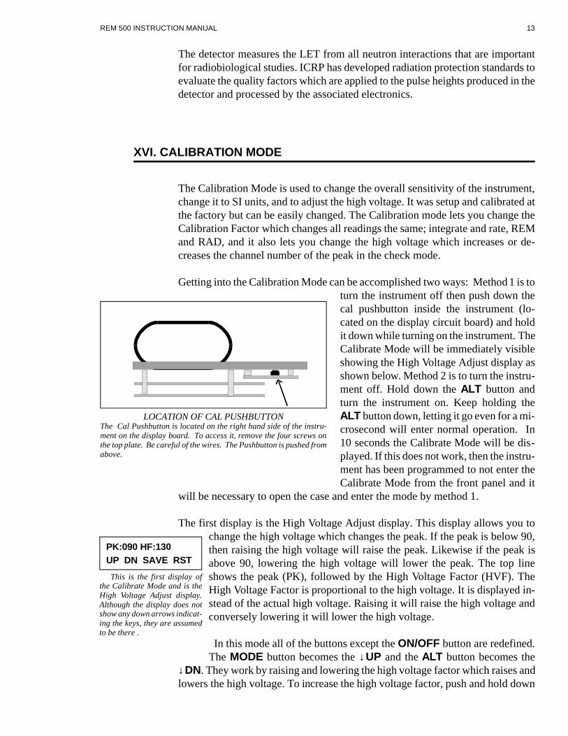
Getting into the Cal i bra tion Mode can be ac com plished two ways: Method 1 is toturn the in stru ment off then push down thecal pushbutton in side the in stru ment (lo -cated on the dis play cir cuit board) and holdit down while turn ing on the in stru ment. The Cal i brate Mode will be im me di ately vis i bleshow ing the High Volt age Ad just dis play asshown be low. Method 2 is to turn the in stru -ment off. Hold down the ALT but ton andturn the in stru ment on. Keep hold ing theALT but ton down, let ting it go even for a mi -cro sec ond will en ter nor mal op er a tion. In10 sec onds the Cal i brate Mode will be dis -played. If this does not work, then the in stru -ment has been pro grammed to not en ter theCal i brate Mode from the front panel and it
will be nec es sary to open the case and en ter the mode by method 1.
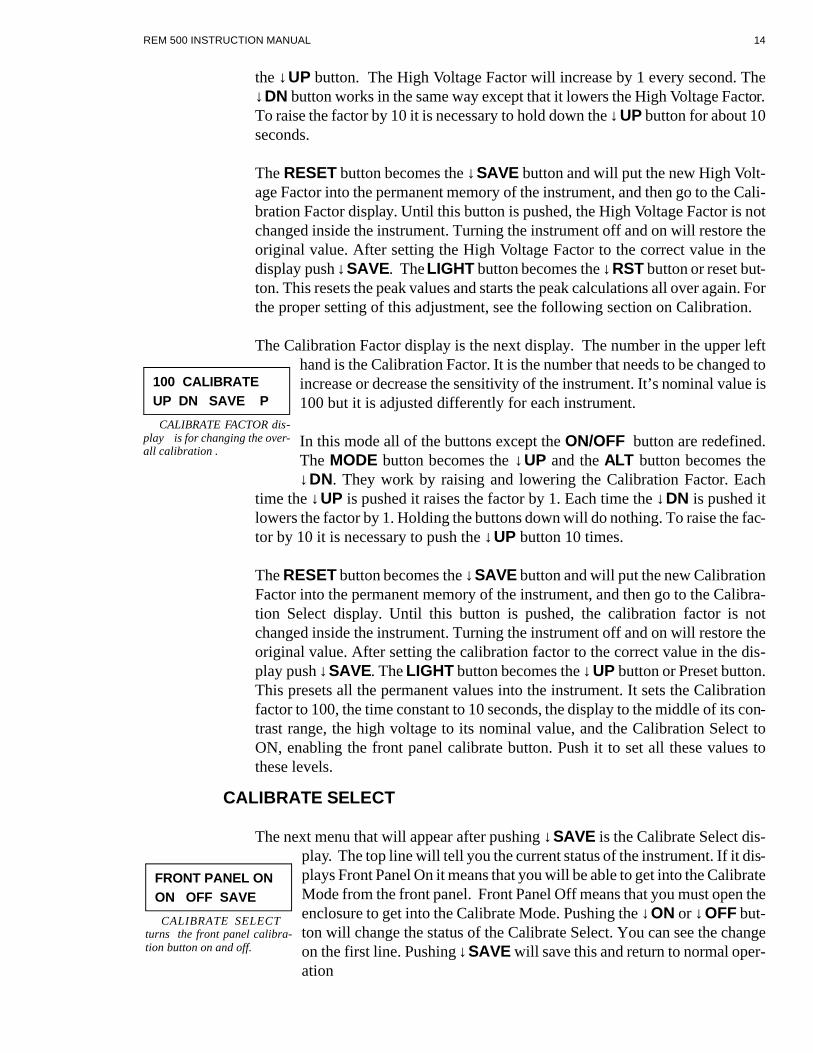
The first dis play is the High Volt age Ad just dis play. This dis play al lows you tochange the high volt age which changes the peak. If the peak is be low 90,then rais ing the high volt age will raise the peak. Like wise if the peak isabove 90, low er ing the high volt age will lower the peak. The top lineshows the peak (PK), fol lowed by the High Volt age Fac tor (HVF). TheHigh Volt age Fac tor is pro por tional to the high volt age. It is dis played in -stead of the ac tual high volt age. Raising it will raise the high volt age andcon versely low er ing it will lower the high volt age.
In this mode all of the but tons ex cept the ON/OFF but ton are re de fined.The MODE but ton be comes the ↓UP and the ALT but ton be comes the
↓DN. They work by rais ing and low er ing the high volt age fac tor which raises and low ers the high volt age. To in crease the high volt age fac tor, push and hold down
REM 500 INSTRUCTION MANUAL 13
LOCATION OF CAL PUSHBUTTON The Cal Pushbutton is lo cated on the right hand side of the in stru -ment on the dis play board. To ac cess it, re move the four screws onthe top plate. Be care ful of the wires. The Pushbutton is pushed fromabove.
PK:090 HF:130UP DN SAVE RST
This is the first dis play ofthe Cal i brate Mode and is theHigh Volt age Ad just dis play.Al though the dis play does notshow any down ar rows in di cat -ing the keys, they are as sumedto be there .
the ↓UP but ton. The High Volt age Fac tor will in crease by 1 ev ery sec ond. The↓DN but ton works in the same way ex cept that it low ers the High Volt age Fac tor.To raise the fac tor by 10 it is nec es sary to hold down the ↓UP but ton for about 10sec onds.
The RE SET but ton be comes the ↓SAVE but ton and will put the new High Volt -age Fac tor into the per ma nent mem ory of the in stru ment, and then go to the Cal i -bra tion Fac tor dis play. Un til this but ton is pushed, the High Volt age Fac tor is notchanged in side the in stru ment. Turn ing the in stru ment off and on will re store theorig i nal value. Af ter set ting the High Volt age Fac tor to the cor rect value in thedis play push ↓SAVE. The LIGHT but ton be comes the ↓RST but ton or re set but -ton. This re sets the peak val ues and starts the peak cal cu la tions all over again. Forthe proper set ting of this ad just ment, see the fol low ing sec tion on Cal i bra tion.
The Cal i bra tion Fac tor dis play is the next dis play. The num ber in the up per lefthand is the Cal i bra tion Fac tor. It is the num ber that needs to be changed toin crease or de crease the sen si tiv ity of the in stru ment. It’s nom i nal value is100 but it is ad justed dif fer ently for each in stru ment.
In this mode all of the but tons ex cept the ON/OFF but ton are re de fined.The MODE but ton be comes the ↓UP and the ALT but ton be comes the↓DN. They work by rais ing and low er ing the Cal i bra tion Fac tor. Each
time the ↓UP is pushed it raises the fac tor by 1. Each time the ↓DN is pushed itlow ers the fac tor by 1. Holding the but tons down will do noth ing. To raise the fac -tor by 10 it is nec es sary to push the ↓UP but ton 10 times.
The RE SET but ton be comes the ↓SAVE but ton and will put the new Cal i bra tionFac tor into the per ma nent mem ory of the in stru ment, and then go to the Cal i bra -tion Se lect dis play. Un til this but ton is pushed, the cal i bra tion fac tor is notchanged in side the in stru ment. Turn ing the in stru ment off and on will re store theorig i nal value. Af ter set ting the cal i bra tion fac tor to the cor rect value in the dis -play push ↓SAVE. The LIGHT but ton be comes the ↓UP but ton or Pre set but ton.This pre sets all the per ma nent val ues into the in stru ment. It sets the Cal i bra tionfac tor to 100, the time con stant to 10 sec onds, the dis play to the mid dle of its con -trast range, the high volt age to its nom i nal value, and the Cal i bra tion Se lect toON, en abling the front panel cal i brate but ton. Push it to set all these val ues tothese lev els.
CAL I BRATE SE LECT
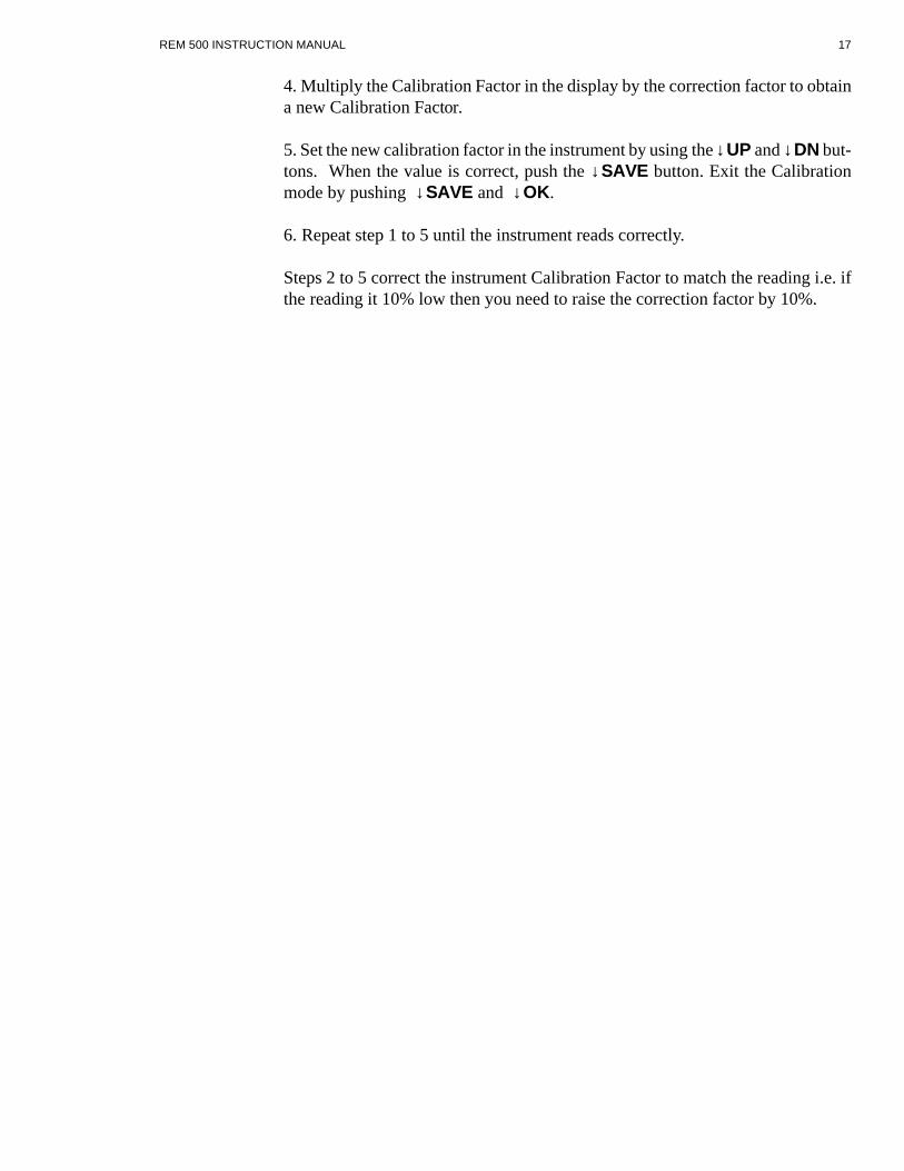
The next menu that will ap pear af ter push ing ↓SAVE is the Cal i brate Se lect dis -play. The top line will tell you the cur rent sta tus of the in stru ment. If it dis -plays Front Panel On it means that you will be able to get into the Cal i brate Mode from the front panel. Front Panel Off means that you must open theen clo sure to get into the Cal i brate Mode. Pushing the ↓ON or ↓OFF but -ton will change the sta tus of the Cal i brate Se lect. You can see the changeon the first line. Pushing ↓SAVE will save this and re turn to nor mal op er -a tion
REM 500 INSTRUCTION MANUAL 14
100 CALIBRATEUP DN SAVE P
CAL I BRATE FACTOR dis -play is for chang ing the over -all cal i bra tion .
FRONT PANEL ONON OFF SAVE
CAL I BRATE SE LECT turns the front panel cal i bra -tion but ton on and off.

To sum ma rize: If you want the con ve nience of get ting into the cal i brate modewith out open ing the case and are not con cerned with se cu rity of the cal i bratenum ber then push ↓YES and then ↓SAVE. If you do not want any one to be ableto en ter the cal i brate mode with out hav ing to open the case then push ↓OFF and↓SAVE.
SI UNITS SE LECT
The next menu that will ap pear af ter push ing the cal i brate se lect is the SI UnitsSe lect dis play. The choice is ei ther for SI units or REM/RAD units.Thiswill ef fect the units in the rate and in te grate dis plays and in the down loaddata.Pushing ↓SI will put the in stru ment in the SI Units mode. Pushingthe ↓REM will put the in stru ment in the Rem/Rad units mode. Pushing the ↓OKwill re sult in no change.
REM 500 INSTRUCTION MANUAL 15
SELECT UNITS SI REM OK
SI UNITS SE LECT chooses the units for the dis plays.Rad/Rem or Sv/Gy are thechoices.

XVII. CALIBRATING THE INSTRUMENT
The in stru ment is eas ily cal i brated. There are two stages to the cal i bra tion. Thefirst is to ad just the high volt age so the chan nel num bers cor re spond to known en -er gies. The sec ond stage is to ex pose the in stru ment to a cal i brated neu tron source to set the over all sen si tiv ity of the in stru ment.
RE QUIRED: Cal i brated neu tron source
Both stages use the cal i brate mode. Please read the pre vi ous sec tion on how to en -ter in the cal i brate mode. The first stage of the cal i bra tion is the ad just ment of thehigh volt age. This is ac com plished by:
1. En ter the Cal i brate mode. You will be in the High Volt age Ad just dis play. (Seesec tion XVI. for in struc tions on how to en ter the Cal i brate Mode.)
2. Wait about 15 to 30 sec onds for the high volt age to sta bi lize.
3. Push the ↓RST but ton to re start the peak cal cu la tions.
4. Wait 30 sec onds to 1 min ute for the peak to sta bi lize.
5. We want the peak to be in chan nel 90. If it is not in chan nel 90 then it is nec es -sary to change the high volt age. If the peak is be low chan nel 90 then it is nec es -sary to raise the high volt age, and if it is above chan nel 90 it is nec es sary to lowerthe high volt age. You should set it to chan nel 90 ± 3 chan nels. Raising the HighVolt age Fac tor by 1 will raise the peak about 1/2 chan nel.
Re peat steps 2, 3, 4, and 5 over un til the peak is on chan nel 90 ± 3 chan nels. When you are sat is fied with the read ing, push the SAVE but ton. This will save the val -ues and change the dis play to the Cal i brate Ad just dis play. Exit the cal i bra tiondis plays by push ing ↓SAVE, ↓SAVE and ↓OK .
This com pletes the high volt age ad just ment stage. The next stage is to check andif nec es sary ad just the over all sen si tiv ity of the in stru ment.
1. Using the cal i brated neu tron source, ex pose the in stru ment to a known quan tityof ra di a tion. It is de sir able to ex pose it in the in te grate range for a pe riod of timesuf fi cient to ac cu mu late at least 1000 counts.
2. Cal cu late the cor rec tion fac tor for the in stru ment.
COR REC TION FACTOR = DE SIRED LEVEL / READING
3. En ter the Cal i bra tion Mode. See the Cal i bra tion Mode sec tion for a de scrip tionof how to get into this mode. By pass the High Volt age Ad just dis play by push ingSAVE. You are now in the Cal i bra tion Ad just dis play.
REM 500 INSTRUCTION MANUAL 16
4. Mul ti ply the Cal i bra tion Fac tor in the dis play by the cor rec tion fac tor to ob taina new Cal i bra tion Fac tor.
5. Set the new cal i bra tion fac tor in the in stru ment by us ing the ↓UP and ↓DN but -tons. When the value is cor rect, push the ↓SAVE but ton. Exit the Cal i bra tionmode by push ing ↓SAVE and ↓OK.
6. Re peat step 1 to 5 un til the in stru ment reads cor rectly.
Steps 2 to 5 cor rect the in stru ment Cal i bra tion Fac tor to match the read ing i.e. ifthe read ing it 10% low then you need to raise the cor rec tion fac tor by 10%.
REM 500 INSTRUCTION MANUAL 17

XVIII. RADIOACTIVE MATERIAL INSIDE DETECTOR
The sealed de tec tor con tains a 1 microcurie ± 20% Cu rium 244 check source. The source ma te rial is de pos ited on the end of a .063 dia stain less steel rod and has agold flash ing over it to se cure the source ma te rial. It is nec es sary for you to in -clude this source ma te rial on your ra dio ac tive ma te ri als li cense.
If it is nec es sary to ship the in stru ment it should have a state ment as to the type ofra dio ac tive ma te rial (Cm244) and the amount (1 microcurie). It should also in -clude the fol low ing state ment in the box so it is the first thing seen when the box is opened. No spe cial pack ag ing ma te rial is re quired other than the nor mal 2" pack -ing ma te rial on all sides and a sturdy card board box.
FROM:___________________________________________________
AD DRESS:________________________________________________
This pack age con forms to the con di tions and lim i ta tions spec i fied in 49 CFR173.421 for Ex cepted Ra dio ac tive Ma te rial, Limited Quan tities, N.O.S., UN2910 and also IATA sec tion 5.7.27.
This is to cer tify that this pack age con forms to all pack ag ing re quire ments of theU.S. De part ment of Trans por ta tion and the In ter na tional Aid Trans port As so ci a -tion rules and reg u la tions re gard ing the ship ment of Ra dio ac tive Ma te rials,Limited Quan tities.
The ra di a tion level on the sur face of this pack age is less than 0.5 mR/hr. No otherla bels re quired.
NAME:____________________________________________
SIG NA TURE:_______________________________________
TI TLE:____________________________________________
The above form serves only as a guide line. Your re quire ments may change de -pend ing on gov ern ment reg u la tions.
REM 500 INSTRUCTION MANUAL 18

XIX. MAINTENANCE MODE
Main te nance Mode is used for elec tronic check out. To get into Main te nanceMode Hold down the MODE and RE SET keys while turn ing the in stru ment on.If the in stru ment has failed see be low. In the Main te nance Mode the 3 dig its in the
up per left of the dis play are the chan nel num ber of the pulse height. Thisranges from 000 to 255. The next three dig its are the con tents of the pulsecoun ter. Ev ery time a new count is re ceived the coun ter in cre ments by one. The next item is ei ther the let ter H or L. This is the com para tor that checksthe con di tion of the bat tery. If it is L it in di cates a good bat tery, if it is H itin di cates a bad bat tery. The Last item is the num ber of the last switch that
was pushed. The switch num bers are: 1, MODE; 2, ALT; 3, RE SET; 4, LIGHT;and 5, CAL but ton.
The but tons are re de fined and their ab bre vi a tions are show on line 2. The MODEbut ton be comes the ↓MAG or MAG NET but ton. The ALT but ton be comes the ↓ADC but ton. The RE SET but ton is the ↓CLR or CLEAR but ton, and theLIGHT but ton re mains the LIGHT but ton. The ac tion of each of these but tons isde fined be low.
↓MAG Turns on the Mag net at tached to the out side of the de tec tor. This causesthe in ter nal al pha source to ir ra di ate the de tec tor sim u lat ing neu tron events withan av er age en ergy that should be in chan nel 90. The elec tron ics can be tested withthese sig nals. The Dis play should also show the counts, al though the peak en ergyis hard to see be cause of the num ber of counts. Turn the mag net off by push ing↓CLR.
↓ADC Af ter it is pushed the soft ware con stantly re sets the ADC por tion of thecir cuit. It puts a con stant pulse on pin 2 U4 and on pin 13 U3A and on pin 10 U6B.Turn it off by push ing ↓CLR.
↓CLR This but ton clears all the pa ram e ters set by the other but tons. It turns on the in ter rupts and the timer. It turns off the mag net, the ADC re set sig nal and thebeeper.
LIGHT The light is turned on when ever this but ton is pushed and turned off bypush ing ↓CLR. This but ton sends an ‘H’ out the se rial port if the se rial port is in -stalled. It also turns off the in ter rupt and timer.
CAL This turns on the beeper. Pushing ↓CLR turns it off.
If the EEPROM has failed the in stru ment will dis play a dim FAIL URE. If this isthe case then it is nec es sary to re place the EEPROM (U16 on the Dig i tal Board).Af ter re plac ing it en ter the Main te nance Mode and push LIGHT at the fail ure in -di ca tion. This will pro gram the EEPROM with de fault val ues. Then turn the in -stru ment on and off again to re sume nor mal op er a tion. The in stru ment will needto be recalibrated be cause the Cal i bra tion Fac tor is in the EEPROM.
REM 500 INSTRUCTION MANUAL 19
090 000 L3MAG ADC CLR
MAINTENANCE MODE

XX. CIRCUIT DESCRIPTION
The elec tronic cir cuit is bro ken down into two main sec tions; the an a log and thedig i tal cir cuits. Each cir cuit has two printed cir cuit boards as so ci ated with it.
DIG I TAL CIR CUIT
The dig i tal cir cuit com prises the Dig i tal Cir cuit Board and the Dis play Board.Both are shown on sche matic # REM1-002.
POWER SUPPLY
The in stru ment is pow ered by 6 C cells. The neg a tive side of the bat ter ies isswitched to turn the in stru ment on and off. U13 forms an al ter nate ac tion set-resetflip-flop that is con trolled by the front panel on-off switch. The out put of thisflip-flop turns on Q5 which grounds the neg a tive side of the bat tery to turn the in -stru ment on. U13 is al ways pow ered on but its cur rent drain when the in stru mentis off is only a cou ple of microamps.
The bat tery power goes to a 3 ter mi nal reg u la tor, U14 which has a low drop outvolt age. Its out put is + 5V. U17 and U18 form a volt age con verter that changes the + 5V into - 5V, + 8V, and - 8V. U12B is a low bat tery de tec tor used to re set the sys -tem when the bat tery volt age drops too low. When the bat tery volt age gets to 5.4V it puts the sys tem into re set. This causes the dis play to go dim be cause theNSC810 out puts turn into in puts and the con trast is changed. The other half ofU12, U12B, is the low bat tery de tec tor. It switches at about 6V.
MI CRO PRO CES SOR
The mi cro pro ces sor, U1 is an NSC800 and uses the Z80 in struc tion set. It is sup -ported by the ad dress latch U2, EPROM U3, RAMU4, ad dress de coder U10 and var i ous other gates, U7, U8, U9, and U11. The os cil la tor X1,R2,C2,and C3os cil lates at 4.0 MHz. It is the timebase for the in stru -ment.
ADC CON TROL
The ADC is mem ory mapped just like all the otherpe riph er als. Read ing it ac ti vates the out put of U9Cand this con trols the sig nal ADC RE SET. This is theonly sig nal that re sets the ADC.
When a con ver sion is ready, it sig nals the sys temthrough the INTR line.
REM 500 INSTRUCTION MANUAL 20
LOCATION OF HIGH VOLTAGE CONTROL The High Volt age Con trol is lo cated on the left hand side of the in -stru ment on the an a log board. To ac cess it re move the four screwson the top plate. Be care ful of the wires. Turn ing the con trol clock -wise raises the peak, turn ing it coun ter-clockwise low ers it.

IN/OUT
The In/Out ports for the sys tem are in the NSC810, U15. This chip has an I/O, aRAM and a timer. The RAM is used for the stack, the timer is used to gen er ate the1 sec ond heart beat from T0 out. This goes to the NMI in put on the mi cro pro ces -sor. The var i ous ports are used as fol lows:
PA0, Pin 21 con trols the elec tro mag net, L1, on the side of the de tec tor. To turn onL1, Pin 21 U15 goes high. This turns on the gate of Q2. Q2 brings the P2:4 end ofL1 to ground turn ing it on. The other side of L1 goes to un reg u lated bat tery volt -age, VBAT.
PA1, Pin 22 con trols the buzzer in the same way that the elec tro mag net is con -trolled.
PA2, Pin 23 con trols the front panel backlight. To turn on the light Pin 23 U15goes high (It is nor mally low). This turns off Q4 whose LCDLED end now goesto ward VBAT be cause of pullup re sis tor R14. This turns on Q1 on the dis playboard which turns on the LCD lamp.
PA3, Pin 24, and PA4 Pin 25, are not used and are pulled up us ing RN2.
PA5, Pin 26 con trols the CS or Chip se lect in put on the EEPROM.
PA6, Pin 27 con trols the SK or clock in put on the EEPROM.
PA7, Pin 28 con trols the DI or Data In put line of the EEPROM.
PB0, Pin 29 re ceives the DO or Data Out put line from the EEPROM.
PB1, Pin 30 is the in put from the CAL switch on the front panel.
PB2, Pin 31 is the in put from the low bat tery de tec tor U12A.
PB3, Pin 32 is the in put from the LIGHT switch on the front panel.
PB4, Pin 33 is the in put from the RE SET switch on the front panel.
PB5, Pin 34 is the in put from the ALT switch on the front panel.
PB6, Pin 35 is the in put from the MODE switch on the front panel.
All the switches are nor mally high be cause of pullup re sis tor net work RN2.
The four pushbuttons, S3, 4, 5, & 6 are all also con nected to D3, 4, 5, & 6. Whenany of the pushbuttons are pushed, it grounds RSTC, through the di ode. RSTC isan in ter rupt in put to the mi cro pro ces sor.
REM 500 INSTRUCTION MANUAL 21
PC0, Pin 37 is the LSB of the R-2R lad der net work used to gen er ate the volt agesfor the LCD con trast.
PC1, Pin 38 is bit 1 of the R-2R lad der net work used to gen er ate the volt ages forthe LCD con trast.
PC2, Pin 39 is bit 2 of the R-2R lad der net work used to gen er ate the volt ages forthe LCD con trast.
PC3, Pin 1 is the MSB of the R-2R lad der net work used to gen er ate the volt agesfor the LCD con trast.
PC4, Pin 2 and PC5, Pin 5 are not used and are pulled up by RN2.
DIS PLAY
The LCD dis play is U6. It has a con trast in put that is con trolled by U5 and theR-2R lad der net work U7 thru R13. This is the dig i tal con trol of the con trast. R5 isthe coarse set for the con trast.
EEPROM
The EEPROM holds 128 bytes of data even when the power is off. Only 7 bytesare used.
SE RIAL PORT
U19 and U20 com prise the se rial port. U19 is the UART and U20 is the volt agedriv ers for RS-232. The UART has its own crys tal, X2.
AN A LOG CIR CUIT
The an a log cir cuit is on two cir cuit boards, the Preamp and the An a log Cir cuitBoard. They are shown in sche matic # REM1-001.
HIGH VOLT AGE POWER SUPPLY
The sup ply out put, for the de tec tor, is around 500V. U9A is an os cil la tor whichpro duces a 2 usec pulse ev ery .4 msec. This drives U9B which ex pands the pulsewidth and turns it on and off de pend ing on the out put of U10. The out put of U9drives Q5 which in turn drives T1. This is a step up trans former. Its sec ond ary isrec ti fied by D5 and fil tered by R46, C31 and in the preamp by C4, C3, and R5.The high volt age is mea sured by re sis tor di vider R47 and R48 and R49. U10 com -pares this volt age to that set by R51, the high volt age con trol and the DAC, andturns on and off the os cil la tor in U9B to reg u late the volt age. R4,and R2 are avolt age di vider to pro vide the he lix in the de tec tor with the cor rect volt age. TheDAC al lows the high volt age to be ad justed by the front panel and con sists of the
REM 500 INSTRUCTION MANUAL 22

lad der net work, R56 to R71. The shift reg is ter U11 shifts and latches the se rialdata from the mi cro pro ces sor to the lad der net work
PREAMP
The high gain charge sen si tive preamp uses a low noise 2N4416 as the in put FET.Q2 pro vides bias for Q1. Q3 is an im ped ance con verter and Q4 is the out putbuffer. Feed back is by R15 and the small amount of stray ca pac i tance across it isthe feed back ca pac i tor. The out put of the preamp is a se ries of ramps. The in putpulse drives the out put pos i tive, and then the sig nal slowly de cays back to wardground. TP1 is an in put for an ex ter nal pul sar.
POST AM PLI FIERS
R17 is the pole zero con trol. U1’s four am pli fi ers shape the pulses for use by theADC. R28x sets the gain.
MCA
U5, a volt age com para tor, and U6 a flip flop start the ADC con ver sion. U5A de -tects the peak above the Low Level Discriminator (LLD). The sig nal then is am -pli fied by U2A and U2B. They form a closed loop to charge ca pac i tor C22 to thepeak value of the in put pulse. The out put of U2A drives the in put of the An a log toDig i tal Con verter, U4. U7 times the con ver sion. U3A and U3D re set the peakcatcher. The ref er ence volt age of 2.5V for the ADC is set by U8. R32 sets the Low Level Discriminator, be low which the pulses will not ini ti ate a con ver sion. Themi cro pro ces sor af ter pro cess ing the sig nal, re sets the ADC by J4:10.
XXI. ELECTRONIC ADJUSTMENTS
There are 4 elec tronic ad just ments. All con trols are in de pend ent and do not needto be done in any or der; they were fac tory set and do not usu ally need ad just ment.Re placing the de tec tor would ne ces si tate ad just ing the Pole Zero, the high volt -age and do ing a cal i bra tion.
HIGH VOLT AGE
The High Volt age con trol is on the bot tom right of the An a log Cir cuit Board. Setthe High Volt age Fac tor in the High Volt age Ad just dis play of the Cal i brate modeto 130. Exit the Cal i brate mode. En ter the Check mode and look at the peak un -der the Check Mode. Ad just the high volt age un til the peak is on chan nel 90 ± 2chan nels.
REM 500 INSTRUCTION MANUAL 23

CON TRAST
The Coarse Con trast con trol on the lower right hand side of the Dig i tal Board ad -justs the con trast of the dis play. The Con trast ad just from the front panel finetunes this value. To set the pot:
1. Turn the in stru ment on, press MODE then ↓NEXT to get into the dis playchange mode. Push the ↓DISPL but ton 20 times. The con trast will get dark, thenjump to light and get dark again. There are 12 steps in the ad just ment, and ev erytime the ↓DISPL pushbutton is pushed it changes the level 1 step.
2. Ad just the Coarse Con trast con trol un til it seems that the 12 steps are in themid dle of the range of the dis play. The light est dis play should be just vis i ble.
LLD
The LLD, on the up per left of the An a log Board, is set with a volt me ter.
1. At tach a volt me ter neg a tive lead to Test Point TP5. At tach the pos i tive lead toTest Point TP3. Ad just the LLD SET con trol un til the volt me ter reads 158 mil li -volts.
2. This ad just ment can be checked with a mer cury pul sar con nected be tween TP1and ground, TP5. En ter main te nance mode and ad just the pul sar to chan nel 10.Then slowly lower the pul sar and note the low est chan nel that is dis played on theleft of the dis play. Raise the level back to around chan nel 10 and slowly lower itagain. Do this a cou ple of times to check the low est chan nel num ber. It should bechan nel 5. If it is a higher num ber then lower the LLD slightly and try it again.
POLE ZERO
The Pole Zero is on the up per left of the An a log Board. Con nect an os cil lo scopebe tween ground, TP5 and pin 1 of U1. En ter the Main te nance Mode and turn onthe mag net. Ad just the Pole Zero con trol fully CCW. Then ad just the con trol un tilthe bot tom of each pulse is even with the base line of all the pulses.
REM 500 INSTRUCTION MANUAL 24
XXII. TROUBLE SHOOTING NOTES
1. A mer cury pul sar can be used to test the in stru ment. It con nects to TP1 andground (TP5) on the An a log Board.
2. Pressing the CAL but ton on the front panel af ter the unit is turned on will ter mi -nate the 15 sec ond self check at power up. This is use ful for test ing the in stru mentes pe cially if you have to turn it on and off many times.
3. If the in stru ment does not work, and there is power to the chips, then turn the in -stru ment off short pin 1 and 2 of the NSC810 and turn power back on. This willcause the pro gram to send out a pulse train on pin 1 of the NSC810. If this oc curs,then the mi cro pro ces sor is work ing. You can dis con nect the fol low ing to see if itworks: U5 LCD dis play, U4-RAM, U19-UART, U20, U16, U12, U5, U11, andU8. The pulse does not need any of these. If they are re moved and it works, thentry putt ing them in and see if the pulses are still there.
4. If there is no dis play then try chang ing the con trast. It may be that the con trast is too light. The coarse con trast may also need chang ing.
5. The two cir cuit boards hinge on one side. Undo the two screws on the side op -po site the hinges on each board and they will open like a fan.
REM 500 INSTRUCTION MANUAL 25

XXIII. QUALITY FACTORS
Quality Factors for each channel as pre programmed into the REM-500 MCA VS1.0
REM 500 INSTRUCTION MANUAL 26
QF = QF *10CHAN #
QF = 4 ;1QF = 7 QF = 11 QF = 14QF = 17 ;5QF = 20QF = 25QF = 27QF = 30 QF = 32 ;10QF = 35QF = 37QF = 40QF = 42QF = 45 ;15QF = 47QF = 50QF = 52QF = 54QF = 57 ;20QF = 58QF = 61QF = 62QF = 64 QF = 67 ;25QF = 69QF = 72 QF = 73QF = 75QF = 78 ;30QF = 80QF = 82 QF = 84QF = 87QF = 88 ;35QF = 90 QF = 93QF = 94QF = 97 QF = 99 ;40QF = 100QF = 103QF = 105QF = 106 QF = 109 ;45QF = 110QF = 113QF = 114 QF = 116QF = 118 ;50QF = 120 QF = 121QF = 124QF = 126QF = 127 ;55QF = 129 QF = 131QF = 132QF = 135QF = 136 ;60QF = 139QF = 140QF = 142QF = 144QF = 145 ;65
QF = QF * 10CHAN #
QF = 147QF = 149QF = 151QF = 152QF = 153 ;70QF = 156QF = 157QF = 158QF = 160QF = 162 ;75QF = 163QF = 165QF = 166QF = 168QF = 170 ;80QF = 171QF = 172QF = 173QF = 174QF = 176 ;85QF = 177QF = 178QF = 179QF = 182QF = 183 ;90QF = 184QF = 186QF = 187QF = 188QF = 189 ;95QF = 191QF = 192QF = 193QF = 194QF = 196 ;100QF = 197QF = 198QF = 199QF = 200QF = 202 ;105QF = 202QF = 203QF = 204QF = 205QF = 207 ;110QF = 208QF = 208QF = 209QF = 210QF = 212 ;115QF = 212QF = 213QF = 214QF = 215QF = 215 ;120QF = 217QF = 218QF = 219QF = 219QF = 220 ;125QF = 222 QF = 222QF = 223QF = 224QF = 224 ;130
QF = QF * 10CHAN #
QF = 225QF = 226QF = 226QF = 228QF = 228 ;135QF = 229QF = 229QF = 230QF = 230QF = 231 ;140QF = 233QF = 233QF = 234QF = 234QF = 235 ;145QF = 235QF = 236QF = 236QF = 238QF = 238 ;150QF = 238QF = 239QF = 239QF = 240QF = 240 ;155QF = 240QF = 241QF = 241 QF = 243QF = 243 ;160QF = 243QF = 244QF = 244QF = 244QF = 245 ;165QF = 245QF = 245QF = 246QF = 246QF = 246 ;170QF = 246QF = 248QF = 248QF = 248QF = 248 ;175QF = 248QF = 248QF = 248QF = 248QF = 248 ;180QF = 248QF = 248QF = 248QF = 248QF = 248 ;185QF = 248QF = 248QF = 248QF = 248QF = 248 ;190QF = 248QF = 248QF = 248QF = 248QF = 248 ;195
QF = QF * 10CHAN #
QF = 248QF = 248QF = 248QF = 248QF = 248 ;200QF = 248QF = 248 QF = 248QF = 248QF = 248 ;205QF = 248QF = 248QF = 248QF = 248QF = 248 ;210QF = 248QF = 248QF = 248QF = 248QF = 248 ;215QF = 248QF = 248QF = 248QF = 248 QF = 248 ;220QF = 248QF = 248QF = 248QF = 248QF = 248 ;225QF = 248QF = 248QF = 248QF = 248QF = 248 ;230QF = 248QF = 248QF = 248QF = 248QF = 248 ;235
QF = 248QF = 248QF = 248QF = 248QF = 248 ;240QF = 248QF = 248QF = 248QF = 248QF = 248 ;245QF = 248QF = 248QF = 248QF = 248QF = 248 ;250QF = 248QF = 248QF = 248QF = 248QF = 248 ;255
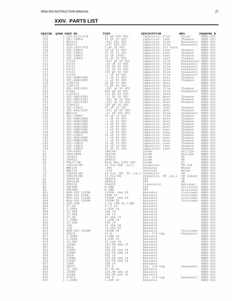
XXIV. PARTS LIST
DESIGN QUAN PART NO TYPE DE SCRIP TION MFG DRAWING # C01 1 212-5315-47K 47 pF 600 VDC Ca pac i tor, film Xicon REM1-001 C02 1 581-33M16 33 uF 10 VDC Ca pac i tor, tant Thomson REM1-001 C03 1 EF6473 .047 600 VDC Ca pac i tor, film Panasonic REM1-001 C04 1 EF6473 .047 600 VDC Ca pac i tor, film Panasonic REM1-001 C05 1 232-1000-005 5 pF 50 VDC Ca pac i tor, slv mica REM1-001 C06 1 581-33M10 33 uF 10 VDC Ca pac i tor, tant Thomson REM1-001 C07 1 581-33M10 33 uF 10 VDC Ca pac i tor, tant Thomson REM1-001 C08 1 581-10M10 10 uF 10VDC Ca pac i tor, tant Thomson REM1-001 C10 1 581-10M10 10 uF 10 VDC Ca pac i tor, tant Thomson REM1-001 C11 1 P3102 .001 uF 50 VDC Ca pac i tor, film Pansasonic REM1-001 C12 1 P3103 .01 uF 50 VDC Ca pac i tor, film Panasonic REM1-001 C13 1 P3101 100 pF 50 VDC Ca pac i tor, film Panasonic REM1-001 C14 1 P3103 .01 uF 50 VDC Ca pac i tor, film Panasonic REM1-001 C15 1 P3101 100 pF 50 VDC Ca pac i tor, film Panasonic REM1-001 C16 1 P3104 .1 uF 50 VDC Ca pac i tor, film Panasonic REM1-001 C17 1 581-UDW104M1 .1 uF 50 VDC Ca pac i tor, mono Thomson REM1-001 C18 1 581-UDW104M1 .1 uF 50 VDC Ca pac i tor, mono Thomson REM1-001 C19 1 21RD722 22 pF 50 VDC Ca pac i tor, mono REM1-001 C20 1 21RD710 10 pF 50 VDC Ca pac i tor, mono REM1-001 C21 1 581-UEZ102K1 .001 uF 50 VDC Ca pac i tor, film Thomson REM1-001 C22 1 P3681 680 pF 50 VDC Ca pac i tor, film Panasonic REM1-001 C23 1 21RD610 100 pF 50 VDC Ca pac i tor, mono REM1-001 C24 1 581-UEZ103K1 .01 uF 50 VDC Ca pac i tor, mono Thomson REM1-001 C25 1 581-UEZ102K1 .001 uF 50 VDC Ca pac i tor, mono Thomson REM1-001 C26 1 581-UEZ102K1 .001 uF 50 VDC Ca pac i tor, mono Thomson REM1-001 C27 1 21RD610 100 pF 50 VDC Ca pac i tor, mono REM1-001 C28 1 581-47M16 47 uF 16 VDC Ca pac i tor, tant Thomson REM1-001 C29 1 581-UEZ102K1 .001 uF 50 VDC Ca pac i tor, mono Thomson REM1-001 C30 1 EF6103 .01 uF 600 VDC Ca pac i tor, film Panasonic REM1-001 C32 1 581-33M10 33 uF 10 VDC Ca pac i tor, film Thomson REM1-001 C33 1 581-UDW104M1 .1 uF 50 VDC Ca pac i tor, mono Thomson REM1-001 C34 1 581-UDW104M1 .1 uF 50 VDC Ca pac i tor, mono Thomson REM1-001 C35 1 581-UDW104M1 .1 uF 50 VDC Ca pac i tor, mono Thomson REM1-001 C36 1 581-UDW104M1 .1 uF 50 VDC Ca pac i tor, mono Thomson REM1-001 C37 1 581-UDW104M1 .1 uF 50 VDC Ca pac i tor, mono Thomson REM1-001 C38 1 581-UDW104M1 .1 uF 50 VDC Ca pac i tor, mono Thomson REM1-001 C39 1 581-33M10 33 uF 10 VDC Ca pac i tor, tant Thomson REM1-001 C40 1 581-UDW104M1 .1 uF 50 VDC Ca pac i tor, mono Thomson REM1-001 C41 1 581-UDW104M1 .1 uF 50 VDC Ca pac i tor, mono Thomson REM1-001 C42 1 581-33M10 33 uF 10 VDC Ca pac i tor, tant Thomson REM1-001 C43 1 581-10M10 10 uF 10 VDC Ca pac i tor, tant Thomson REM1-001 C44 1 581-10M10 10 uF 10 VDC Ca pac i tor, tant Thomson REM1-001 D1 1 1N4148PH 1N4148 Di ode Philips REM1-001 D2 1 1N4148PH 1N4148 Di ode Philips REM1-001 D3 1 1N5812 1N5812 Di ode HP REM1-001 D4 1 1N5812 1N5812 Di ode HP REM1-001 D5 1 FR107-ND Fast Rec 1000 VDC Di ode DI REM1-001 J1 1 CHS10G-ND 10 Pin HDR .1x.1 Con nec tor CW Ind REM1-001 J2 1 WM1105 .093 Ter mi nal Molex REM1-001 J3 1 WM1105 .093 Ter mi nal Molex REM1-001 J4 1 CHS26G-ND 26 Pin, MT, ST .1x.1 Con nec tor CW REM1-001 P1 1 CHR10G-ND 10 Pin RA Con nec tor, MT .1x.1 CW Indust REM1-001 Q1 1 2N4416A 2N4416 FET GE REM1-001 Q2 1 2N4416A 2N4416 FET GE REM1-001 Q3 1 PN4250 2N4450 Tran sis tor Na tional REM1-001 Q4 1 VN10KM N PWR FET Siliconix REM1-001 Q5 1 VN10KM N PWR FET Siliconix REM1-001 R01 1 MOX-300 1000M 1000M ohm 5% Re sis tor Victoreen REM1-001 R02 1 MOX-300 250M 250M 5% Re sis tor Victoreen REM1-001 R03 1 MOX-300 1000M 1000M ohm 5% Re sis tor Victoreen REM1-001 R04 1 MOX-300 1000M 1000M 5% Re sis tor Victoreen REM1-001 R05 2 299-10M 2 ea 10M 5% 1/8W Re sis tor REM1-001 R06 1 47.5X 47.5 1% Re sis tor REM1-001 R07 1 2.00KX 2.00K 1% Re sis tor REM1-001 R08 1 10.0KX 10K 1% Re sis tor REM1-001 R09 1 10.0KX 10K 1% Re sis tor REM1-001 R10 1 10.0X 10 ohm 1% Re sis tor REM1-001 R11 1 1.00MX 1.00M 1% Re sis tor REM1-001 R12 1 10.0KX 10K 1% Re sis tor REM1-001 R13 1 10Q 10 ohm 5% Re sis tor REM1-001 R14 1 10Q 10 ohm 5% Re sis tor REM1-001 R15 1 MOX-300 1000M 1000M 5% Re sis tor Victoreen REM1-001 R16 1 CEG14 10 K Pot, 3/8 top Panasonic REM1-001 R17 1 4.99KX 4.99K 1% Re sis tor REM1-001 R18 1 2.00KX 2.00K 1% Re sis tor REM1-001 R19 1 10.0KX 10 ohm 1% Re sis tor REM1-001 R20 1 100KX 100.0K ohm 1% Re sis tor REM1-001 R21 1 562X 562 1% Re sis tor REM1-001 R22 1 100KX 100.0K ohm 1% Re sis tor REM1-001 R23 1 100KX 100.0K ohm 1% Re sis tor REM1-001 R24 1 562X 562 1% Re sis tor REM1-001 R25 1 100KX 100.0K ohm 1% Re sis tor REM1-001 R26 1 100KX 100.0K ohm 1% Re sis tor REM1-001 R27 1 10KX 10K 1% Re sis tor REM1-001 R28 1 CEG15 100 K Pot, 3/8 top Panasonic REM1-001 R29 1 51.1KX 51.1K 5% Re sis tor REM1-001 R30 1 100KX 100.0K ohm 1% Re sis tor REM1-001 R31 1 100KX 100.0K ohm 1% Re sis tor REM1-001 R32 1 01B15 100 K Pot, 3/8 top Panasonic REM1-001 R33 1 1.00KX 1.00K 1% Re sis tor REM1-001
REM 500 INSTRUCTION MANUAL 27

DESIGN QUAN PART NO TYPE DE SCRIP TION MFG DRAWING # R34 1 1.50KX 1.50K 1% Re sis tor REM1-001 R35 1 1.00KX 1.00K 1% Re sis tor REM1-001 R36 1 681X 681 1% Re sis tor REM1-001 R37 1 20.0K 20K 1% Re sis tor REM1-001 R38 1 10KQ 10K 5% Re sis tor REM1-001 R39 1 10KQ 10K 5% Re sis tor REM1-001 R40 1 10.0KX 10.0K 1% Re sis tor REM1-001 R41 1 200Q 200 5% Re sis tor REM1-001 R42 1 511KX 511K 1% Re sis tor REM1-001 R43 1 2.7KX 2.7K 5% Re sis tor REM1-001 R44 1 100KX 100K 1% Re sis tor REM1-001 R45 1 100Q 100 ohm 5% Re sis tor REM1-001 R46 1 299-10M 10M 5% Re sis tor REM1-001 R47 1 MOX-300 1000M 1000M 5% Re sis tor Victoreen REM1-001 R48 1 1.00MX 1.00M 1% Re sis tor REM1-001 R49 1 1.00MX 1.00M 1% Re sis tor REM1-001 R50 1 100.0K 100K ohm 1% Re sis tor REM1-001 R51 1 01B15 100K Pot, 3/4" rect Panasonic REM1-001 R52 1 300KX 300.0K 1% Re sis tor REM1-001 R53 1 10Q 10 ohm 5% Re sis tor REM1-001 R54 1 10Q 10 ohm 5% Re sis tor REM1-001 R55 1 499.0K 499K ohm 1% Re sis tor REM1-001 R56 1 100.0K 100K ohm 1% Re sis tor REM1-001 R57 1 100.0K 100K ohm 1% Re sis tor REM1-001 R58 1 100.0K 100K ohm 1% Re sis tor REM1-001 R59 1 100.0K 100K ohm 1% Re sis tor REM1-001 R60 1 100.0K 100K ohm 1% Re sis tor REM1-001 R61 1 100.0K 100K ohm 1% Re sis tor REM1-001 R62 1 100.0K 100K ohm 1% Re sis tor REM1-001 R63 1 100.0K 100K ohm 1% Re sis tor REM1-001 R64 1 49.9K 49.9K ohm 1% Re sis tor REM1-001 R65 1 49.9K 49.9K ohm 1% Re sis tor REM1-001 R66 1 49.9K 49.9K ohm 1% Re sis tor REM1-001 R67 1 49.9K 49.9K ohm 1% Re sis tor REM1-001 R68 1 49.9K 49.9K ohm 1% Re sis tor REM1-001 R69 1 49.9K 49.9K ohm 1% Re sis tor REM1-001 R70 1 49.9K 49.9K ohm 1% Re sis tor REM1-001 R71 1 100.0K 100K ohm 1% Re sis tor REM1-001 T1 1 T1-REM500 Pot core Trans former HPI REM1-001 TP1 1 V1072-ND T44 Stake, test point Vec tor REM1-001 TP2 1 V1072-ND T44 Stake, test point Vec tor REM1-001 TP3 1 V1072-ND T44 Stake, test point Vec tor REM1-001 TP4 1 V1072-ND T44 Stake, test point Vec tor REM1-001 TP5 1 V1072-ND T44 Stake, test point Vec tor REM1-001 TP6 1 V1072-ND T44 Stake, test point Vec tor REM1-001 U01 1 TL064CN TL064 Quad op amp TI REM1-001 U02 1 TL062CP TL062 Dual op amp TI REM1-001 U03 1 CD4066NCN 4066 Switch, quad Na tional REM1-001 U04 1 ADC0804LCN ADC0804 A-D Conv 8 bit Na tional REM1-001 U05 1 LM393N LM 393 Dual Com para tor Na tional REM1-001 U06 1 CD4013BCN 4013 Dual D Flip Flop Na tional REM1-001 U07 1 511-CD4098 4098 Mono Multivibrator SGS REM1-001 U08 1 LM385Z LM 385Z 2.5 V Ref er ence Na tional REM1-001 U09 1 ICM7556IPD ICL7665 Dual Timer Har ris REM1-001 U10 1 TLC271CP TLC271 Op amp TI REM1-001 U11 1 4094 CD4094BE Shift Reg is ter REM1-001 B1 6 P106 C Al ka line Bat tery Panasonic REM1-002 BZ1 1 MEB-12-5C Piezo Buzzer GPE REM1-002 C01 1 581-4.7M10 4.7 uF 10VDC Ca pac i tor, tant Thomp son REM1-002 C02 1 21RD747 47 pF Ca pac i tor, mono REM1-002 C03 1 21RD722 22 pF Ca pac i tor, mono REM1-002 C04 1 581-UDW104M1 .1 uF 50 VDC Ca pac i tor, mono Thomp son REM1-002 C05 1 581-UDW104M1 .1 uF 50 VDC Ca pac i tor, mono Thomp son REM1-002 C06 1 581-UDW104M1 .1 uF 50 VDC Ca pac i tor, mono Thomp son REM1-002 C07 1 581-100M10 100 uF 10VDC Ca pac i tor, tant Thomp son REM1-002 C08 1 581-33M10 33 uF 10VDC Ca pac i tor, tant Thomp son REM1-002 C09 1 581-UDW104M1 .1 uF 50 VDC Ca pac i tor, mono Thomp son REM1-002 C10 1 581-UDW104M1 .1 uF 50 VDC Ca pac i tor, mono Thomp son REM1-002 C11 1 581-UDW104M1 .1 uF 50 VDC Ca pac i tor, mono Thomp son REM1-002 C12 1 581-UDW104M1 .1 uF 50 VDC Ca pac i tor, mono Thomp son REM1-002 C13 1 581-UDW104M1 .1 uF 50 VDC Ca pac i tor, mono Thomp son REM1-002 C14 1 581-UDW104M1 .1 uF 50 VDC Ca pac i tor, mono Thomp son REM1-002 C15 1 581-UDW104M1 .1 uF 50 VDC Ca pac i tor, mono Thomp son REM1-002 C16 1 581-UDW104M1 .1 uF 50 VDC Ca pac i tor, mono Thomp son REM1-002 C17 1 581-UDW104M1 .1 uF 50 VDC Ca pac i tor, mono Thomp son REM1-002 C18 1 581-47M16 47 uF 16 VDC Ca pac i tor, tant Thomp son REM1-002 C19 1 581-47M16 47 uF 16 VDC Ca pac i tor, tant Thomp son REM1-002 C20 1 581-47M16 47 uF 16 VDC Ca pac i tor, tant Thomp son REM1-002 C21 1 581-47M16 47 uF 16 VDC Ca pac i tor, tant Thomp son REM1-002 C22 1 581-47M16 47 uF 16 VDC Ca pac i tor, tant Thomnpson REM1-002 C23 1 581-47M16 47 uF 16 VDC Ca pac i tor, tant Thomp son REM1-002 C24 1 21RD710 10 pF Ca pac i tor, mono REM1-002 C25 1 21RD710 10 pF Ca pac i tor, mono REM1-002 C26 1 581-10M10 10 uF 10 VDC Ca pac i tor, tant Thomp son REM1-002 C27 1 581-10M10 10 uF 10 VDC Ca pac i tor, tant Thomp son REM1-002 C28 1 581-10M10 10 uF 10 VDC Ca pac i tor, tant Thomp son REM1-002 C29 1 581-10M10 10 uF 10 VDC Ca pac i tor, tant Thomp son REM1-002 D01 1 1N4148PH 1N4148 Di ode Philips REM1-002 D02 1 1N4002GI 1N4002 Di ode Gen Inst REM1-002 D03 1 1N4148PH 1N4148 Di ode Philips REM1-002 D04 1 1N4148PH 1N4148 Di ode Philips REM1-002 D05 1 1N4148PH 1N4148 Di ode Philips REM1-002 D06 1 1N4148PH 1N4148 Di ode Philips REM1-002 D07 1 1N5817 Schottky Di ode Dio Inc REM1-002 D08 1 1N5817 Schottky Di ode Dio Inc REM1-002
REM 500 INSTRUCTION MANUAL 28

DESIGN QUAN PART NO TYPE DE SCRIP TION MFG DRAWING # J1 1 CHR26G-ND 26 Pin RA HDR .1x.1 Con nec tor CW Ind REM1-002 J2 1 WM4204 4 Pin SIP HDR Con nec tor Molex REM1-002 J4 1 WM4205 7 Pin SIP HDR .1 Con nec tor Molex REM1-002 L1 1 EM-R1A 12 V Elec tro mag net Mag net Sal REM1-002 P1 1 CHR26G-ND 26 Pin RA HDR .1x.1 Con nec tor CW Ind REM1-002 P2 1 WM2002 4 Pin SIP WIRE Con nec tor Molex REM1-002 P3 1 CHS26G-ND 26 Pin ST HDR .1x.1 Con nec tor CW Ind REM1-002 Q1 1 VN10KM N PWR FET REM1-002 Q2 1 VN10KM N PWR FET REM1-002 Q3 1 VN10KM N PWR FET REM1-002 Q4 1 VN10KM N PWR FET REM1-002 Q4 1 VN10KM N PWR FET REM1-002 Q5 1 VN10KM N PWR FET REM1-002 R01 1 100KQ 100K 5% Re sis tor REM1-002 R02 1 1MQ 1M 5% Re sis tor REM1-002 R03 1 100KQ 100K 5% Re sis tor REM1-002 R04 1 100KX 100.0K 1% Re sis tor REM1-002 R05 1 36C24 20 K 1t 6mm Po ten ti om e ter Panasonic REM1-002 R06 1 49.9KX 49.9K 1% Re sis tor REM1-002 R07 1 49.9KX 49.9K 1% Re sis tor REM1-002 R08 1 49.9KX 49.9K 1% Re sis tor REM1-002 R09 1 100KX 100.0K 1% Re sis tor REM1-002 R10 1 100KX 100.0K 1% Re sis tor REM1-002 R11 1 100KX 100.0K 1% Re sis tor REM1-002 R12 1 100KX 100.0K 1% Re sis tor REM1-002 R13 1 100KX 100.0K 1% Re sis tor REM1-002 R14 1 10KQ 10K 5% Re sis tor REM1-002 R15 1 10Q 10 5% Re sis tor REM1-002 R16 1 49.9KX 49.9K 1% Re sis tor REM1-002 R17 1 29MF250-1.5M 1.5M 1% Re sis tor REM1-002 R18 1 499KX 499K 1% Re sis tor REM1-002 R19 1 100KQ 100K 5% Re sis tor REM1-002 R20 1 10KQ 10K 5% Re sis tor REM1-002 R21 1 120KQ 120K 5% Re sis tor REM1-002 R22 1 1.5MQ 1.5M 5% Re sis tor REM1-002 R23 1 390KQ 390K 5% Re sis tor REM1-002 R24 1 3.3KQ 3.3K 5% Re sis tor REM1-002 R25 1 100KQ 100K 5% Re sis tor REM1-002 RN1 1 770-101-R100K 100K x 9 Re sis tor net work CTS REM1-002 RN2 1 770-101-R10K 10K x 9 Re sis tor net work CTS REM1-002 S1 1 P8037S Push SPST Switch tiny Panasonic REM1-002 S2 1 P8037S Push SPST Switch tiny Panasonic REM1-002 S3 1 P8036S Push SPST Switch Panasonic REM1-002 S4 1 P8036S Push SPST Switch Panasonic REM1-002 S5 1 P8036S Push SPST Switch Panaconic REM1-002 S6 1 P8036S Push SPST Switch Panasonic REM1-002 S7 1 P8036S Push SPST Switch Panasonic REM1-002 S8 1 P8036S Push SPST Switch Panasonic REM1-002 TP1 1 V1072-ND T44 Stake Vec tor REM1-002 TP2 1 V1072-ND T44 Stake Vec tor REM1-002 TP3 1 V1072-ND T44 Stake Vec tor REM1-002 U01 1 NSC800N-3I NSC800 Mi cro pro ces sor 8 bit Na tional REM1-002 U02 1 MM74HC574N 74HC574 Oc tal D F/F Na tional REM1-002 U03 1 27C64 EPROM REM1-002 U04 1 UM6116-3L 6116 RAM 1K x 8 REM1-002 U05 1 TLC271CP Op Amp TI REM1-002 U06 1 SSM2160MYB-G 16 x 2 w/bklt LED LCD al pha nu meric SHELLY REM1-002 U07 1 MM74HC08N 74HC08 Quad AND Na tional REM1-002 U08 1 MM74HC02N 74HC02 Quad Nor gate Na tional REM1-002 U09 1 MM74HC04 74HC04 Hex in verter Na tional REM1-002 U10 1 MM74HC138N 74HC138 3 to 8 De coder Na tional REM1-002 U11 1 MM74HC74AN 74HC74 Dual Flip Flop Na tional REM1-002 U12 1 ICL7665CPA ICL7665 Volt age De tec tor Maxim REM1-002 U13 1 511-4069 4069 Hex In verter SGS REM1-002 U14 1 LM2931T-5.0 LM 2931 5 V Reg u la tor TO220 Na tional REM1-002 U15 1 NSC810AN-3I NSC810 PIA In ter face Na tional REM1-002 U16 1 93C46P 93C46 EEPROM 1K ICT REM1-002 U17 1 ICL7660SCPA ICL7660 Volt Con verter Har ris REM1-002 U18 1 ICL7660SCPA ICL7660 Volt Con verter Har ris REM1-002 U19 1 SCC2691AC1N24 SCC2691 UART Signetics REM1-002 U20 1 MAX232CPE MAX232CPE Volt Conv RS232 Maxim REM1-002 X1 1 CTX080 4.000 MHz Crys tal CTS REM1-002 X2 1 CTX049 3.6864 MHz Crys tal CTS REM1-002 M01 1 11093-A-1032-1B HAN DLE Amatom REM1-023 M02 1 REM1-007 Top Plate HPI REM1-023 M03 1 REM1-015 Switch Panel HPI REM1-023 M04 1 REM1-004 Shield, An a log Bd HPI REM1-023 M05 1 LEXAN WIN DOW HPI REM1-023 M06 1 GAS KET, SWITCH HPI REM1-023 M07 1 REM1-002 DIG I TAL CIR CUIT BD HPI REM1-023 M08 1 REM1-002 CIR CUIT BD AN A LOG HPI REM1-023 M09 1 REM1-0021 PCB FRONT PANEL HPI REM1-023 M10 1 See REM1-018 LCD DIS PLAY REM1-023 M11 1 REM1-025-2 Ca ble, Rib bon HPI REM1-023 M12 1 REM1-025-3 Ca ble, Rib bon HPI REM1-023 M13 1 REM1-025-1 Ca ble, Rib bon HPI REM1-023 M14 4 6-32 x 5/8 Screw, Pan Phil PS REM1-023 M15 6 #6 Washer, Ny lon REM1-023 M16 2 10-32 x 1/2 Screw, Pan Phil PS REM1-023 M17 4 6-32 x 3/8 Screw, Set SS REM1-023 M18 2 354K-ND 6-32 x 1 FF Spacer, An gle Key stone REM1-023 M19 2 J181 6-32 x 1 Spacer, Hex EF JOHN SON REM1-023 M20 20 6-32 x 1/4 Screw, PAN PH PS REM1-023 M21 26 #6 Int Star Lockwasher REM1-023 M22 2 353K-ND 6-32 x 3/4 FF Spacer, An gle Key stone REM1-023
REM 500 INSTRUCTION MANUAL 29

DESIGN QUAN PART NO TYPE DE SCRIP TION MFG DRAWING # M23 2 J246 6-32 x 7/8 Spacer, Rnd EF John son REM1-023 M24 4 6-32 x 1/8 Screw, Pan PH PS REM1-023 M25 4 2-56 x 3/8 Screw, Pan PH PS REM1-023 M26 4 J230 #4 x 1/8 Spacer, Ny lon EF John son REM1-023 M27 4 313-1437-014 #6 x 7/16 Spacer, Rnd EF John son REM1-023 M28 4 #2 Lockwasher, Int Star REM1-023 M29 4 2-56 Nut, Hex PS REM1-023 M30 4 6-32 x 3/4 Screw, Pan PH PS REM1-023 M31 5 REM1-026 Ny lon Spacer, But ton REM1-023 M32 5 J178 6-32 x 1/2 Spacer, Hex EF John son REM1-023 M33 1 1/8 x 18" O ring, Rub ber REM1-023 M34 2 6-32 x 3/8 Screw, Pan PH PS REM1-023 M35 2 J168 #6 x 1/8 Spacer, Rnd EF John son REM1-023 M36 1 4-40 x 1/2 Screw, Pan Ny lon REM1-023 M37 1 4-40 Nut, Ny lon REM1-023 M01 1 REM1-005 Box, Bat tery top HPI REM1-024 M02 1 REM1-006 Box, Bat tery Bot tom HPI REM1-024 M03 1 REM1-011 Batt End Plate HPI REM1-024 M04 1 REM1-010 Bracket, Bot tom HPI REM1-024 M05 1 REM1-008 Bat tery Cover HPI REM1-024 M06 1 REM1-013 Bot tom Can HPI REM1-024 M07 1 REM1-014 Mag net Housing HPI REM1-024 M08 1 REM1-009 Bracket, Top HPI REM1-024 M09 1 REM1-003 Cover, Preamp HPI REM1-024 M10 1 REM1-0041 Preamp PCB HPI REM1-024 M11 1 REM1-LET De tec tor HPI REM1-024 M12 1 REM1-028 Neo prene Gas ket, De tec tor HPI REM1-024 M13 1 12VDC Elec tro mag net REM1-024 M14 2 Ball Plungers REM1-024 M15 4 99-600-9 #6 Thumb screw Cap SPI REM1-024 M17 4 6-32 x 1/4 Ssrew, Pan PH PS REM1-024 M18 4 #6 Lockwasher, Int Star REM1-024 M19 4 6-32 x 1/4 Screw, Pan PH PS REM1-024 M20 4 6-32 x 3/8 Spacer, Hex REM1-024 M21 4 6-32 x 3/8 Screw, SHCS SS REM1-024 M22 2 REM1-028 Bat tery Con tact HPI REM1-024 M23 4 6-32 Nut, Hex PS REM1-024 M24 3 10-32 Nut, Hex PS REM1-024 M25 2 #10 Lockwasher, Int Star REM1-024 M26 10 S/6-32 x 1/4 6-32 x 1/4 Screw, Pan Sealing APM Hexsel REM1-024 M27 3 4-40 x 1/2 Screw, CS PH 100deg REM1-024 M28 2 10-32 x 1/2 Screw, Set SS REM1-024 M29 1 10-32 x 5/16 Screw, Set SS REM1-024 M30 3 4-40 Nut, Hex PS REM1-024 M31 6 #4 Lockwasher, Int Star REM1-024 M32 3 313-6487-020 4-40 x 5/8 Spacer, Hex EF John son REM1-024 M33 3 #4 Washer PS REM1-024 M34 2 6-32 x 3/8 Screw, Set SS REM1-024 M35 1 REM1-025-4 Ca ble, SIP HPI REM1-024 M36 4 6-32 x 3/8 Screw, Pan PH PS REM1-024 M37 3 4-40 x 1/4 Screw, Pan PH PS REM1-024 M38 1 10-32 x 1/4 Screw, PHCS SS REM1-024 P1 1 CKC26G-ND 26 pin Socket Con nec tor CW REM1-025 P2 1 CKC26G-ND 26 pin Socket Con nec tor CW REM1-025 P3 1 CKC26G-ND 26 pin Socket Con nec tor CW REM1-025 P4 1 CKC26G-ND 26 pin Socket Con nec tor CW REM1-025 P5 1 CKC10G-ND 26 pin Socket Con nec tor CW REM1-025 P6 1 CKC10G-ND 26 pin Socket Con nec tor CW REM1-025 P7 1 WM2002 4 pin Ter mi nal Housing Molex REM1-025 P7-A 4 WM2200 .1 Tin Pins for hous ing Molex REM1-025 W1 1 R025-ND 26 con duc tor 6"long Ca ble, Rib bon OKI REM1-025 W2 1 R020-ND 10 con duc tor 10"long Ca ble, Rib bon OKI REM1-025 W3 1 R025-ND 26 con duc tor 3"long Ca ble, Rib bon OKI REM1-025
REM 500 INSTRUCTION MANUAL 30

XXV. PARTS LOCATIONS AND SCHEMATICS
PARTS LOCATION CIRCUIT BOARD
REM 500 INSTRUCTION MANUAL 31
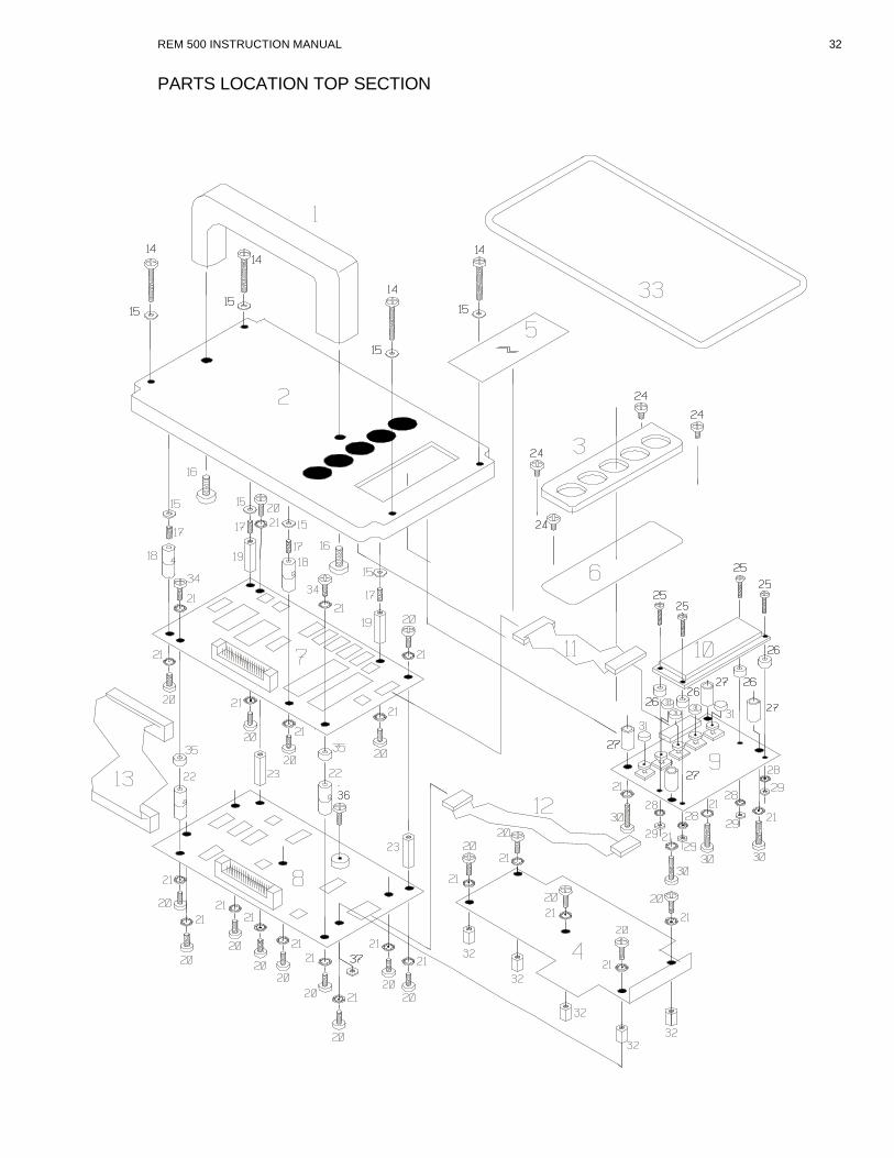
PARTS LOCATION TOP SECTION
REM 500 INSTRUCTION MANUAL 32
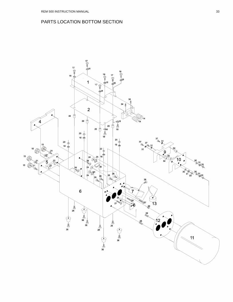
PARTS LOCATION BOTTOM SECTION
REM 500 INSTRUCTION MANUAL 33

SCHEMATICS
REM 500 INSTRUCTION MANUAL 34

REM 500 INSTRUCTION MANUAL 35