tdr s-parameters and differential meas cas2010
TRANSCRIPT
8/18/2019 TDR S-Parameters and Differential Meas CAS2010
http://slidepdf.com/reader/full/tdr-s-parameters-and-differential-meas-cas2010 1/20
TDR, S-par, Differential Meas. 1
TDR, S-Parameters &
Differential Measurements
TDR, S-Parameters &
Differential Measurements
TDR, S-Parameters & Differential Measurements
Mar. 2008Page 2
Agenda
Introduction
TDR theory of operation
Real Example: Samtec Golden Standard Board
• Single Ended Impedance
• Coupling Effects
• Odd & Even Modes
• Differential Impedance
Relating TDR/TDT & S-Parameters
• TDR – more than reflections
• 4-Port Single Ended vs 2-Port Mixed Mode (Differential)
Important Factors in DTDR Accuracy
8/18/2019 TDR S-Parameters and Differential Meas CAS2010
http://slidepdf.com/reader/full/tdr-s-parameters-and-differential-meas-cas2010 2/20
TDR, S-par, Differential Meas. 2
TDR, S-Parameters & Differential Measurements
Mar. 2008Page 3
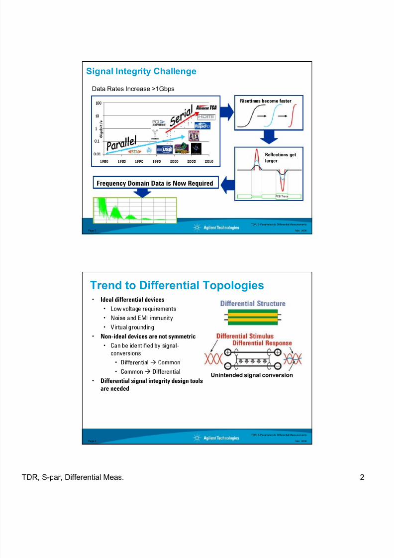
Signal Integrity Challenge
Data Rates Increase >1Gbps
Risetimes become faster
Reflections get
larger
Frequency Domain Data is Now Required
TDR, S-Parameters & Differential Measurements
Mar. 2008Page 4
• Ideal differential devices
• Low voltage requirements
• Noise and EMI immunity
• Virtual grounding
• Non-ideal devices are not symmetric
• Can be identified by signal-
conversions
• Differential Common
• Common Differential
• Differential signal integrity design tools
are needed
Trend to Differential Topologies
Unintended signal conversion
8/18/2019 TDR S-Parameters and Differential Meas CAS2010
http://slidepdf.com/reader/full/tdr-s-parameters-and-differential-meas-cas2010 3/20
TDR, S-par, Differential Meas. 3
TDR, S-Parameters & Differential Measurements
Mar. 2008Page 5
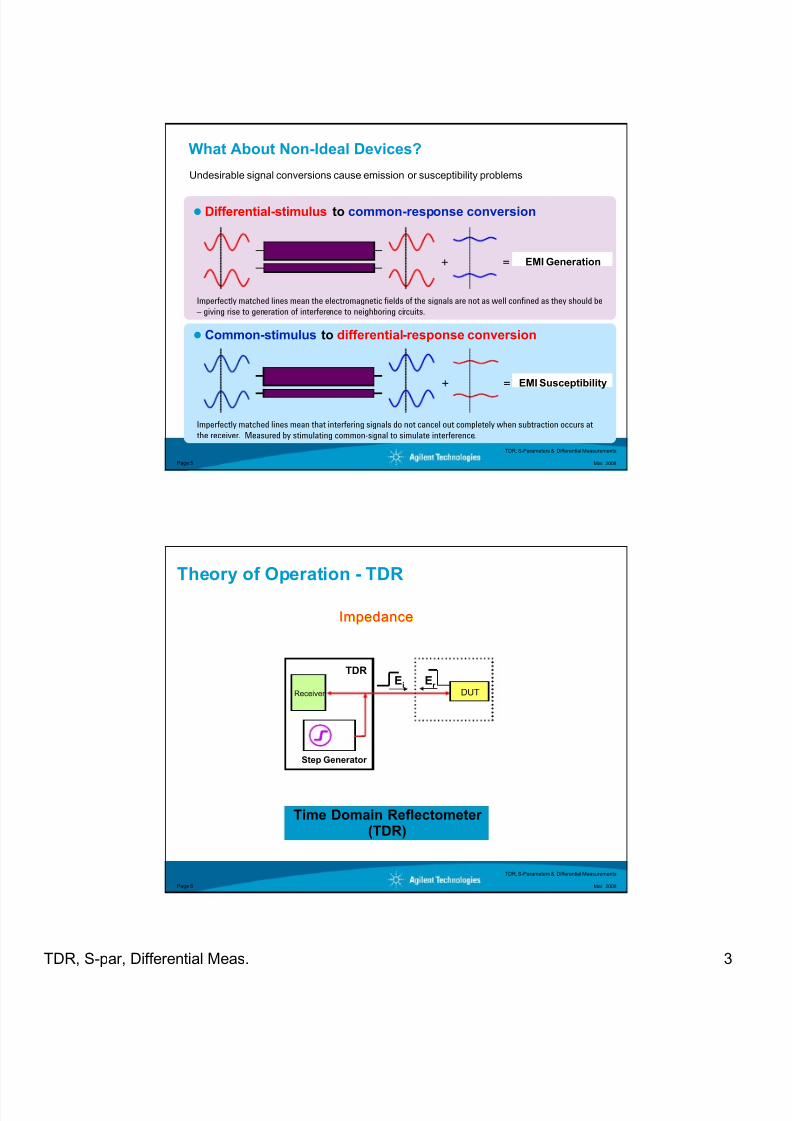
What About Non-Ideal Devices?
Undesirable signal conversions cause emission or susceptibility problems
Differential-stimulus to common-response conversion
+
Common-stimulus to differential-response conversion
EMI Generation
EMI Susceptibility+
=
=
Imperfectly matched lines mean the electromagnetic fields of the signals are not as well confined as they should be
– giving rise to generation of interference to neighboring circuits.
Imperfectly matched lines mean that interfering signals do not cancel out completely when subtraction occurs at
the receiver. Measured by stimulating common-signal to simulate interference.
TDR, S-Parameters & Differential Measurements
Mar. 2008Page 6
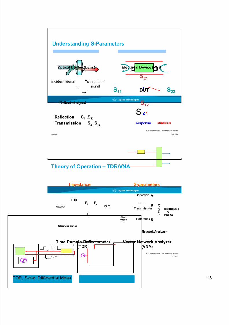
Theory of Operation - TDR
EiReceiver
Step Generator
DUT
Er
Time Domain Reflectometer (TDR)
ImpedanceImpedance
TDR
8/18/2019 TDR S-Parameters and Differential Meas CAS2010
http://slidepdf.com/reader/full/tdr-s-parameters-and-differential-meas-cas2010 4/20
TDR, S-par, Differential Meas. 4
TDR, S-Parameters & Differential Measurements
Mar. 2008Page 7
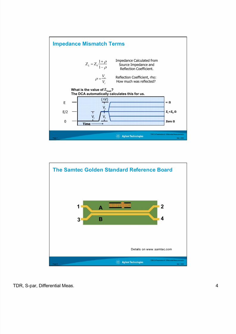
Impedance Mismatch Terms
Zero Ω
∞
Ω
ZL=Z
0ΩE/2
0
E
Vi
Vr
Vr
(Δ V)
ρ
ρ
−
+=
1
10 Z Z L
Impedance Calculated fromSource Impedance andReflection Coefficient.
i
r
V
V = ρ
Reflection Coefficient, rho:How much was reflected?
Time
What is the value of Ζload?
The DCA automatically calculates this for us.
TDR, S-Parameters & Differential Measurements
Mar. 2008Page 8
The Samtec Golden Standard Reference Board
1
3
2
4
A
B
Details on www.samtec.com
8/18/2019 TDR S-Parameters and Differential Meas CAS2010
http://slidepdf.com/reader/full/tdr-s-parameters-and-differential-meas-cas2010 5/20
TDR, S-par, Differential Meas. 5
TDR, S-Parameters & Differential Measurements
Mar. 2008Page 9
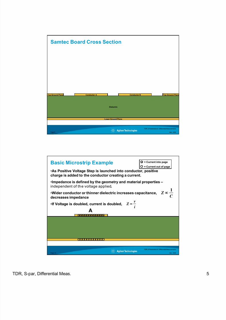
Samtec Board Cross Section
Dielectric
Conductor A Top Ground PlaneTop Ground Plane
Lower Ground Plane
Conductor B
TDR, S-Parameters & Differential Measurements
Mar. 2008Page 10
Basic Microstrip Example
i
v Z
•As Positive Voltage Step is launched into conductor, positive
charge is added to the conductor creating a current.
•Impedance is defined by the geometry and material properties –
independent of the voltage applied.
•Wider conductor or thinner dielectric increases capacitance,
decreases impedance
•If Voltage is doubled, current is doubled,
X X X X X XXXXX
··
XX
X
·
= Current into page
= Current out of page
A
C Z
1∝
·· ·· ·· ·· ··
8/18/2019 TDR S-Parameters and Differential Meas CAS2010
http://slidepdf.com/reader/full/tdr-s-parameters-and-differential-meas-cas2010 6/20
TDR, S-par, Differential Meas. 6
TDR, S-Parameters & Differential Measurements
Mar. 2008Page 11
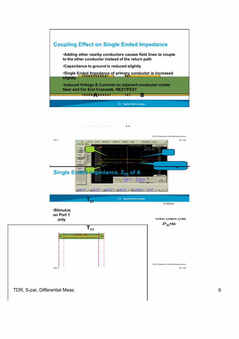
Coupling Effect on Single Ended Impedance
X X X X X XXXXX
•Adding other nearby conductors causes field lines to couple
to the other conductor instead of the return path
•Capacitance to ground is reduced slightly
•Single Ended Impedance of primary conductor is increased
slightly
•Induced Voltage & Currents on adjacent conductor create
Near and Far End Crosstalk, NEXT/FEXT
X
X
A B
X·· ·· ·· ·· ·· ··
··
TDR, S-Parameters & Differential Measurements
Mar. 2008Page 12
Single Ended Impedance, ZSE of A
T31
T11
1
3
Vr=8mV, Vi=200mV, Z0=50Ω
ZASE=54
V=22mV
•Stimulus
on Port 1
only
2
4

8/18/2019 TDR S-Parameters and Differential Meas CAS2010
http://slidepdf.com/reader/full/tdr-s-parameters-and-differential-meas-cas2010 7/20
TDR, S-par, Differential Meas. 7
TDR, S-Parameters & Differential Measurements
Mar. 2008Page 13
Single Ended Impedance of B
A B
•Exactly same as A
•Can be measured with either positive or negative voltage step at
various amplitudes (linear)
X
X X X XX X X XX XX
X ·· ·· ·· ·· ·· ··
··
TDR, S-Parameters & Differential Measurements
Mar. 2008Page 14
Single Ended Impedance, ZSE of B
T13
T33
Vr=7mV, Vi=200mV, Z0=50
ZBSE=54
V=23mV
•Stimulus
on Port 3
only
1
3
2
4
8/18/2019 TDR S-Parameters and Differential Meas CAS2010
http://slidepdf.com/reader/full/tdr-s-parameters-and-differential-meas-cas2010 8/20
TDR, S-par, Differential Meas. 8
TDR, S-Parameters & Differential Measurements
Mar. 2008Page 15
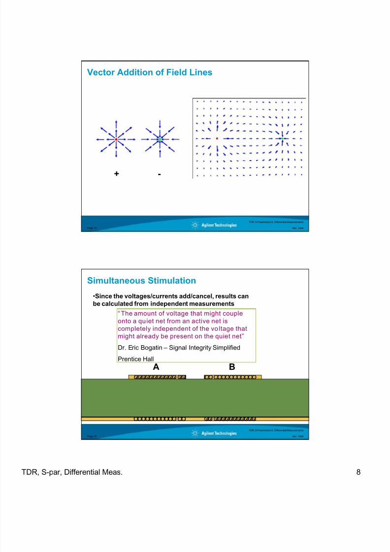
Vector Addition of Field Lines
+ -
TDR, S-Parameters & Differential Measurements
Mar. 2008Page 16
Simultaneous Stimulation
A BX X X X XXXXXX
X
X
X X X XX X X XX X
•Since the voltages/currents add/cancel, results can
be calculated from independent measurements
X
X
X
X
“ The amount of voltage that might couple
onto a qu iet net from an active net is
completely independent of the vo ltage that
might already be present on the quiet net”
Dr. Eric Bogatin – Signal Integrity Simplified
Prentice Hall
·· ·· ·· ·· ·· ·
· ·· ·· ·· ·· ··
··
··

8/18/2019 TDR S-Parameters and Differential Meas CAS2010
http://slidepdf.com/reader/full/tdr-s-parameters-and-differential-meas-cas2010 9/20
TDR, S-par, Differential Meas. 9
TDR, S-Parameters & Differential Measurements
Mar. 2008Page 17
•Odd Mode Impedance- Impedance of a single line, while the pair is driven in the odd mode (only
differential signal, no common signal).
•Even Mode Impedance- Impedance of a single line, while the pair is driven in the even mode
(only common signal, no differential).
•Differential Impedance- Impedance the differential part of a signal will see. (Sum of the Odd
Mode Impedances)
•Common Impedance
- Impedance the common part of a signal will see. (Sum of Even ModeImpedances/4)
Differential Circuit Terminology
TDR, S-Parameters & Differential Measurements
Mar. 2008Page 18
Odd Mode Impedance
A BX X X X XXXXXX
X
X
X X X XX X X XX X
•Defined as Impedance of a single line when voltage on A is
opposite polarity of voltage on B
•Can be measured either by stimulating both lines simultaneously
OR combining currents/voltages from independent measurements
•Zodd is less than ZSE due to induced currents combining (more
current = less impedance)
X
X
X
X·· ·· ·· ·· ·· ·· ··
·· ·· ·· ·· ·· ····
8/18/2019 TDR S-Parameters and Differential Meas CAS2010
http://slidepdf.com/reader/full/tdr-s-parameters-and-differential-meas-cas2010 10/20
TDR, S-par, Differential Meas. 10
TDR, S-Parameters & Differential Measurements
Mar. 2008Page 19
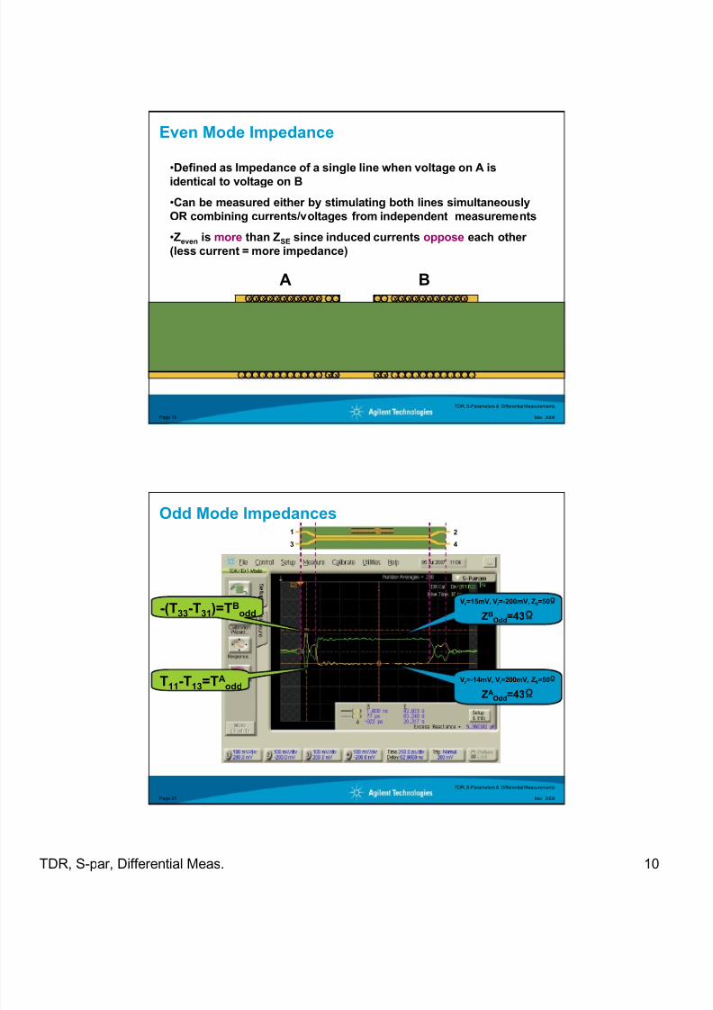
Even Mode Impedance
A BX X X X XXXXXX X X X XX X X XX X
•Defined as Impedance of a single line when voltage on A is
identical to voltage on B
•Can be measured either by stimulating both lines simultaneously
OR combining currents/voltages from independent measurements
•Zeven is more than ZSE since induced currents oppose each other
(less current = more impedance)
XX
X X
X X·· ·· ·· ·· ·· ·· ·· ·· ·· ·· ·· ··
·· ··
TDR, S-Parameters & Differential Measurements
Mar. 2008Page 20
Odd Mode Impedances
-(T33-T31)=TBodd
T11-T13=TAodd
Vr =-14mV, Vi=200mV, Z0=50
ZAOdd=43
Vr =15mV, Vi=-200mV, Z0=50
ZBOdd=43
1
3
2
4
8/18/2019 TDR S-Parameters and Differential Meas CAS2010
http://slidepdf.com/reader/full/tdr-s-parameters-and-differential-meas-cas2010 11/20
TDR, S-par, Differential Meas. 11
TDR, S-Parameters & Differential Measurements
Mar. 2008Page 21
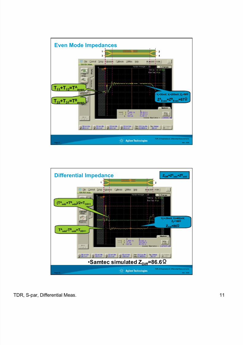
Even Mode Impedances
T33+T31=TBeven
T11+T13=TAeven
Vr =30mV, Vi=200mV, Z0=50
ZAEven=ZB
Even=67
1
3
2
4
TDR, S-Parameters & Differential Measurements
Mar. 2008Page 22
Differential Impedance
(TAodd+TB
odd)/2=TCD11
TAodd-TB
odd=TDD11
Vr =-29mV, Vi=400mV,
Z0=100
ZDiff =86
ZDiff =ZAodd+ZB
odd
•Samtec simulated ZDiff =86.6
1 2
8/18/2019 TDR S-Parameters and Differential Meas CAS2010
http://slidepdf.com/reader/full/tdr-s-parameters-and-differential-meas-cas2010 12/20
TDR, S-par, Differential Meas. 12
TDR, S-Parameters & Differential Measurements
Mar. 2008Page 23
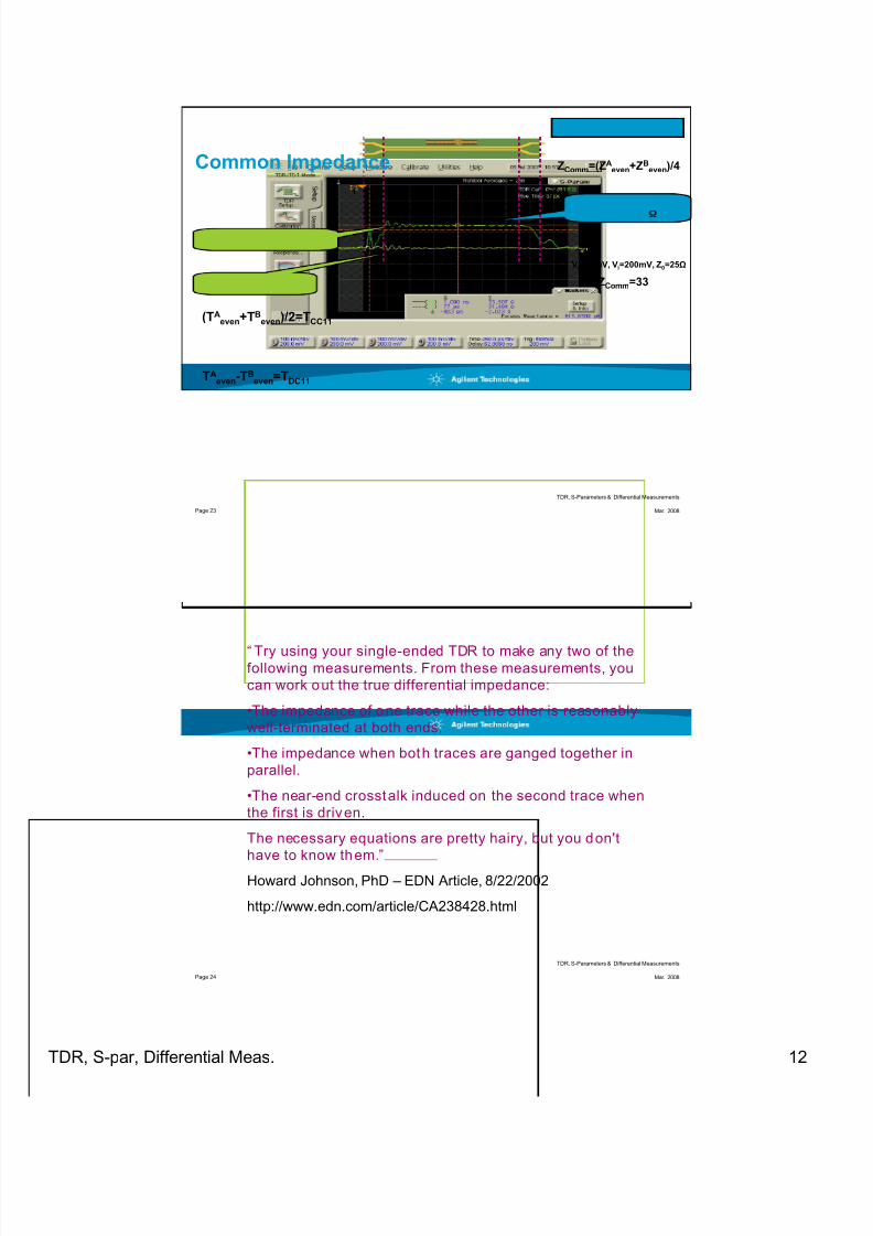
Common Impedance
TAeven-T
Beven=TDC11
(TAeven+TB
even)/2=TCC11
Vr =30mV, Vi=200mV, Z0=25Ω
ZComm=33
ZComm=(ZAeven+ZB
even)/4
1 2
TDR, S-Parameters & Differential Measurements
Mar. 2008Page 24
“ Try using your single-ended TDR to make any two of thefollowing measurements. From these measurements, you
can work out the true differential impedance:
•The impedance of one trace while the other is reasonably
well-terminated at both ends.
•The impedance when both traces are ganged together in
parallel.
•The near-end crosstalk induced on the second trace when
the first is driven.
The necessary equations are pretty hairy, but you don't
have to know them.”
Howard Johnson, PhD – EDN Article, 8/22/2002
http://www.edn.com/article/CA238428.html
8/18/2019 TDR S-Parameters and Differential Meas CAS2010
http://slidepdf.com/reader/full/tdr-s-parameters-and-differential-meas-cas2010 13/20
8/18/2019 TDR S-Parameters and Differential Meas CAS2010
http://slidepdf.com/reader/full/tdr-s-parameters-and-differential-meas-cas2010 14/20
TDR, S-par, Differential Meas. 14
TDR, S-Parameters & Differential Measurements
Mar. 2008Page 27
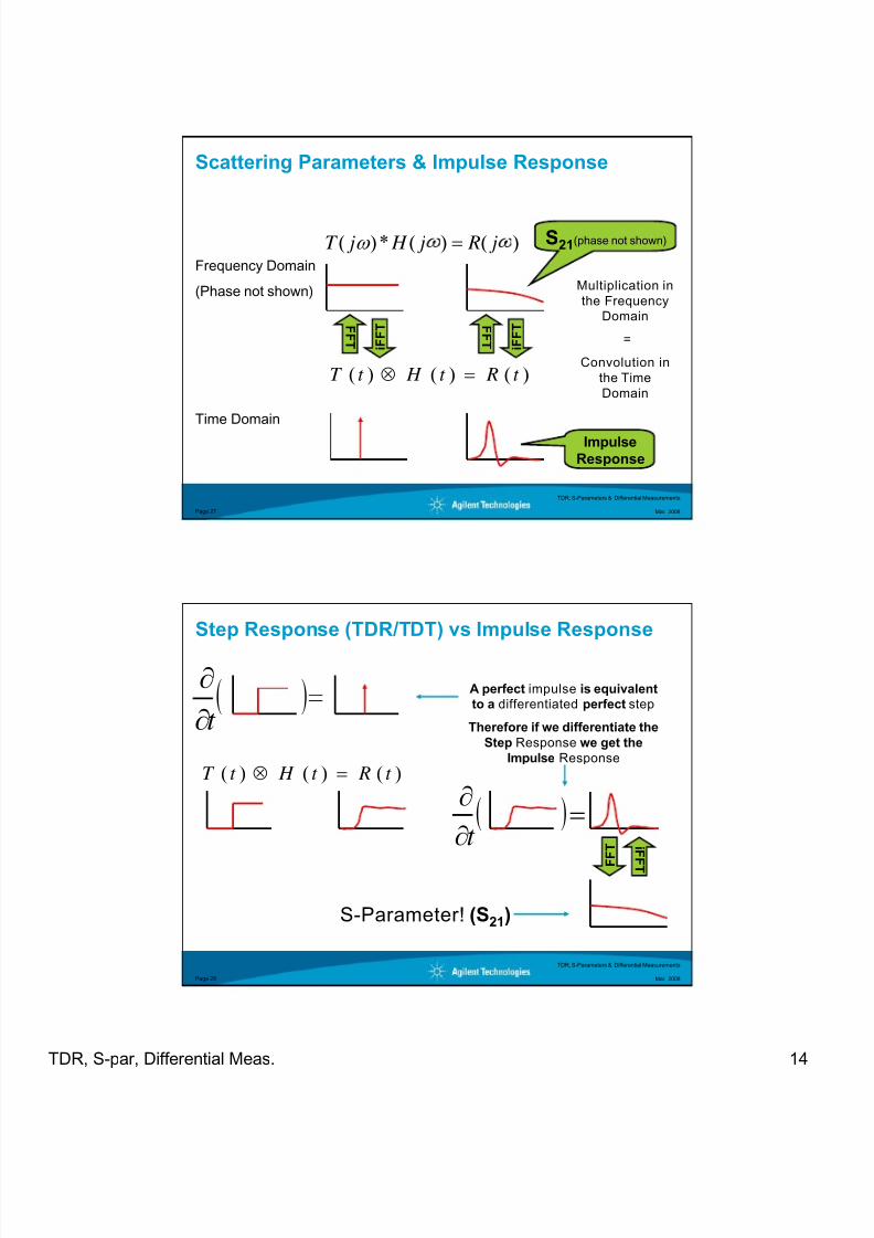
Scattering Parameters & Impulse Response
Frequency Domain
(Phase not shown)
Time Domain
)()(*)( ω j R j H jT =
)()()( t Rt H t T =⊗
Multiplication in
the Frequency
Domain
=
Convolution in
the Time
Domain
F F T
F F T
i F F T
i F F T
S21(phase not shown)
Impulse
Response
TDR, S-Parameters & Differential Measurements
Mar. 2008Page 28
Step Response (TDR/TDT) vs Impulse Response
)()()( t Rt H t T =⊗
( )∂
∂
t
( )=∂
∂
t F F T
i F F
T
A perfect impulse is equivalent
to a differentiated perfect step
Therefore if we differentiate the
Step Response we get the
Impulse Response
S-Parameter! (S21)
8/18/2019 TDR S-Parameters and Differential Meas CAS2010
http://slidepdf.com/reader/full/tdr-s-parameters-and-differential-meas-cas2010 15/20
TDR, S-par, Differential Meas. 15
TDR, S-Parameters & Differential Measurements
Mar. 2008Page 29
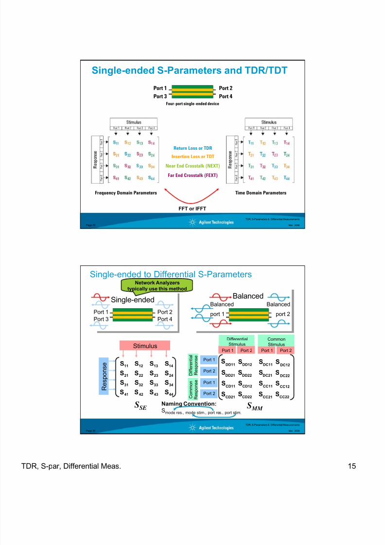
Single-ended S-Parameters and TDR/TDT
Return Loss or TDR
Insertion Loss or TDT
Near End Crosstalk (NEXT)
Far End Crosstalk (FEXT)
Four-port single-ended device
Port 1
Port 3
Port 2
Port 4
Frequency Domain Parameters Time Domain Parameters
FFT or IFFT
TDR, S-Parameters & Differential Measurements
Mar. 2008Page 30
Stimulus
R e s
p o n s e
Port 1
Single-ended
Port 3
Port 2
Port 4
Balanced
port 1
BalancedBalanced
port 2
Port 1 Port 1Port 2 Port 2
DifferentialStimulus
Common
Stimulus
Port 1
Port 2
Port 1
Port 2
D i f f e r e n t i a l
R e s p o n s e
C o m m o n
R e s p o n s e
Naming Convention:
Smode res., mode stim., port res., port stim.
Single-ended to Differential S-ParametersNetwork Analyzers
typically use this method
44434241
34333231
24232221
14131211
SSSS
SSSS
SSSS
SSSS
CC21
CC11
DC21
DC11
S
S
S
CC22
CC12
DC22
DC12
S
S
S
SS
CD21
CD11
DD21
DD11
S
S
S
CD22
CD12
DD22
DD12
S
S
S
SS
SSE S
MM
8/18/2019 TDR S-Parameters and Differential Meas CAS2010
http://slidepdf.com/reader/full/tdr-s-parameters-and-differential-meas-cas2010 16/20
TDR, S-par, Differential Meas. 16
TDR, S-Parameters & Differential Measurements
Mar. 2008Page 31
Port 1
Single-ended
Port 3
Port 2
Port 4port 1
Balanced
port 2
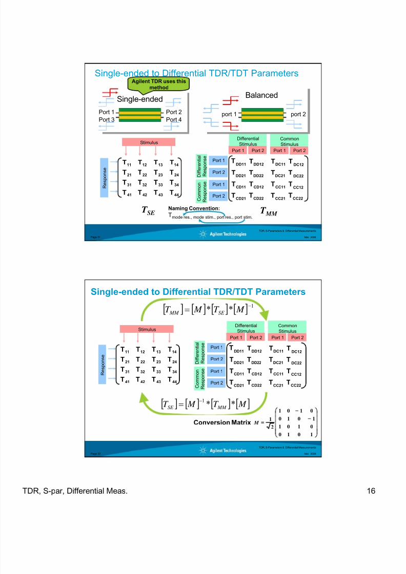
Naming Convention:
Tmode res., mode stim., port res., port stim.
Single-ended to Differential TDR/TDT ParametersAgilent TDR uses this
method
44434241
34333231
24232221
14131211
TTTT
TTTT
TTTT
TTTT
Stimulus
R e s p o n s e
CC21
CC11
DC21
DC11
T
T
T
CC22
CC12
DC22
DC12
T
T
T
TT
CD21
CD11
DD21
DD11
T
T
T
CD22
CD12
DD22
DD12
T
T
T
TT
Port 1 Port 1Port 2 Port 2
Differential
StimulusCommon
Stimulus
Port 1
Port 2
Port 1
Port 2
D i f f e r e n t i a l
R e s p o n s e
C
o m m o n
R
e s p o n s e
T SE T
MM
TDR, S-Parameters & Differential Measurements
Mar. 2008Page 32
44434241
34333231
24232221
14131211
TTTT
TTTT
TTTT
TTTT
Stimulus
R e s p o n s e
CC21
CC11
DC21
DC11
T
T
T
CC22
CC12
DC22
DC12
T
T
T
TT
CD21
CD11
DD21
DD11
T
T
T
CD22
CD12
DD22
DD12
T
T
T
TT
Port 1 Port 1Port 2 Port 2
DifferentialStimulus
Common
Stimulus
Port 1
Port 2
Port 1
Port 2
D i f f e r e n t i a l
R e s p o n s e
C o m m o n
R e s p o n s e
Single-ended to Differential TDR/TDT Parameters
[ ] [ ] [ ] [ ] 1** −
= M T M T SE MM
Conversion Matrix
[ ] [ ] [ ] [ ] M T M T MM SE **1−=
⎟
⎟
⎟
⎟
⎠
⎞
⎜
⎜
⎜
⎜
⎝
⎛
1010
0101
1010
0101
2
1 M

8/18/2019 TDR S-Parameters and Differential Meas CAS2010
http://slidepdf.com/reader/full/tdr-s-parameters-and-differential-meas-cas2010 17/20
TDR, S-par, Differential Meas. 17
TDR, S-Parameters & Differential Measurements
Mar. 2008Page 33
The 4 Matrices of a 4-Port Device
44434241
34333231
24232221
14131211
TTTTTTTT
TTTT
TTTT
CC21
CC11
DC21
DC11
T
T
T
CC22
CC12
DC22
DC12
T
T
T
TT
CD21
CD11
DD21
DD11
T
T
T
CD22
CD12
DD22
DD12
T
T
T
TT
44434241
34333231
24232221
14131211
SSSS
SSSS
SSSS
SSSS
CC21
CC11
DC21
DC11
S
S
S
CC22
CC12
DC22
DC12
S
S
S
SS
CD21
CD11
DD21
DD11
S
S
S
CD22
CD12
DD22
DD12
S
S
S
SS
All 4 Matrices can be
calculated from any 1 of
the 4 Matrices
TDR, S-Parameters & Differential Measurements
Mar. 2008Page 34
DCAj – S-Parameters
Calibrated S-Parameters
•Real-time Update
•Built-in to the GUI
1
3
2
4
8/18/2019 TDR S-Parameters and Differential Meas CAS2010
http://slidepdf.com/reader/full/tdr-s-parameters-and-differential-meas-cas2010 18/20
TDR, S-par, Differential Meas. 18
TDR, S-Parameters & Differential Measurements
Mar. 2008Page 35
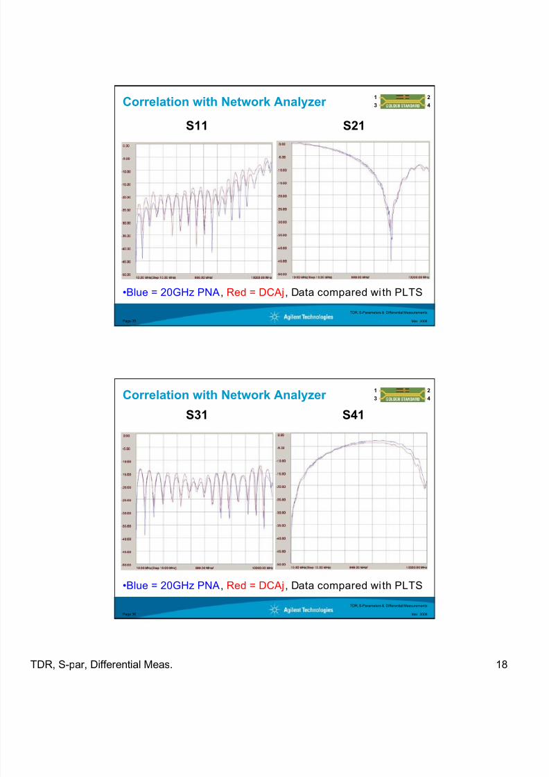
Correlation with Network Analyzer
S11 S21
•Blue = 20GHz PNA, Red = DCAj, Data compared wi th PLTS
1
3
2
4
TDR, S-Parameters & Differential Measurements
Mar. 2008Page 36
Correlation with Network Analyzer
S31 S41
1
3
2
4
•Blue = 20GHz PNA, Red = DCAj, Data compared wi th PLTS
8/18/2019 TDR S-Parameters and Differential Meas CAS2010
http://slidepdf.com/reader/full/tdr-s-parameters-and-differential-meas-cas2010 19/20
TDR, S-par, Differential Meas. 19
TDR, S-Parameters & Differential Measurements
Mar. 2008Page 37
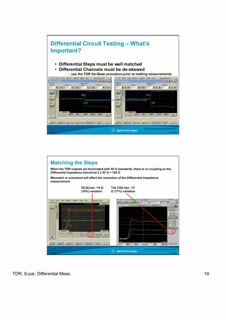
• Differential Steps must be well matched
• Differential Channels must be de-skewed- use the TDR De-Skew procedure prior to making measurements
Differential Circuit Testing – What’s
Important?
TDR, S-Parameters & Differential Measurements
Mar. 2008Page 38
Matching the StepsWhen the TDR outputs are terminated with 50 Ω standards, there is no coupling so theDifferential Impedance should be 2 x 50 Ω = 100 Ω
Mismatch or overshoot will affect the resolution of the Differential Impedance
measurement
DCAj has ~10Ω
(10%) variation
Tek CSA has ~17
Ω (17%) variation
8/18/2019 TDR S-Parameters and Differential Meas CAS2010
http://slidepdf.com/reader/full/tdr-s-parameters-and-differential-meas-cas2010 20/20
TDR S par Differential Meas 20
TDR, S-Parameters & Differential Measurements
Mar. 2008Page 39
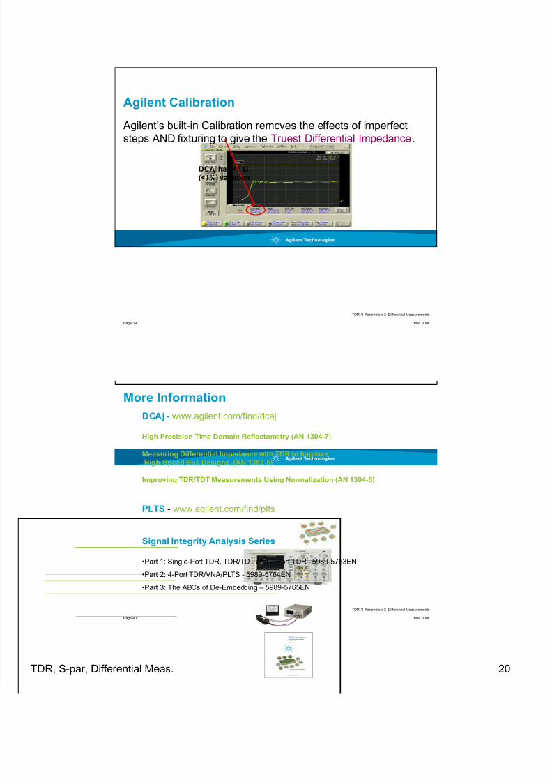
Agilent Calibration
Agilent’s built-in Calibration removes the effects of imperfect
steps AND fixturing to give the Truest Differential Impedance.
DCAj has <1Ω
(<1%) variation
TDR, S-Parameters & Differential Measurements
Mar. 2008Page 40
More Information
DCAj - www.agilent.com/find/dcaj
High Precision Time Domain Reflectometry (AN 1304-7)
Measuring Differential Impedance with TDR to Improve
High-Speed Bus Designs, (AN 1382-5)
Improving TDR/TDT Measurements Using Normalization (AN 1304-5)
PLTS - www.agilent.com/find/plts
Signal Integrity Analysis Series
•Part 1: Single-Port TDR, TDR/TDT and 2-Port TDR - 5989-5763EN
•Part 2: 4-Port TDR/VNA/PLTS - 5989-5764EN
•Part 3: The ABCs of De-Embedding – 5989-5765EN