teaching equipment designer and manufacturer · teaching equipment designer and manufacturer...
TRANSCRIPT
Teaching equipmenT designer and manufacTurer
Teaching equipmenT designer and manufacTurer
APPLIED MECHANICS
fLu
ids
dYn
am
ics
mea
sure
men
TTh
erm
Od
Yna
mic
spr
Oc
ess
eng
inee
rin
gh
Ydra
uLic
spn
eum
aTic
seL
eVaT
Ors
app
Lied
mec
ha
nic
s
prO
du
cTi
On
ac
TiVi
Ties
hVa
c a
nd
Th
erm
aL
eng
inee
rin
g
294
characTeriZaTiOn .................................. p. 295
eLecTricaL and ........................................... p. 316
mechanicaL .................................................... p. 317
sOLid sTaTe phYsYcis ......................... p. 324
3
2
4
1
Of maTeriaLs and sTrucTures
cOnTrOL sYsTem
OsciLLaTOrs
and mechanism
295
Applied Mechanics
tel. +33 (0)4 77 10 10 10 • www.didatec-technologie.com
characTeriZaTiOn Of maTeriaLs and sTrucTures1
• strain gauges connection.• measures of micro deformations relating for the gauges with moun-
ting full-bridge.
• amplification and display of signals from the measurement points for strain gauge
• processing of measured values on the pc
EXPERIMENTAL CAPABILITIES
EXPERIMENTAL CAPABILITIES
• Lcd display• quick connector for strain gauges / output wire• 1 measurement channel
options• compatible with the equipment of the range didaTec integrating
strain gauges
Display• graphic 128x128 points , 16 lines, Lighting: 5 Led white 3 levels.
HanDling• 9 keys (4 soft keys and cursor block) 9 Led of control on the front
panel.• 9 measuring menus (3 menus with freely configurable on 50 func-
tions).• 8 programming menus.
MeMory• multi media card 512 mB card with usB adapter.
inputs• from 9 (sensor supply 5V +/- 0.05V/100mA max stabilized).
optional• rack of 10 additional inputs.
output• 2 outputs for all output modules (analog cable, data, trigger, relay
etc).• usB interface cable pc / sam200.
TEChNICAL dETAILS
TEChNICAL dETAILS
supply• power supply: 230Vac-50hz
supply• electrical supply: 230V - 50 / 60hz 8 accus nimh 9 to 11
V, 1600 mah
DiMensions• LxWxh: 179x232x158 (mm)
SERVICES REQUIREd
SERVICES REQUIREd
Packager - disPlayer for strain gauges in full bridge
sam 010
AMPLIFIER OF MEASUREMENTS FOR STRAINT GAUGES
sam 200

296
Applied Mechanics
FLU
ID D
YNA
MIC
SM
eASU
reM
eNt
tHer
MO
DYN
AM
ICS
PrO
CeS
S
eNG
INee
rIN
GH
YDrA
ULIC
SPN
eUM
AtIC
SeL
eVAt
OrS
APP
LIeD
MeC
HA
NIC
S
PrO
DU
CtI
ON
AC
tIVI
tIeS
HVA
C A
ND
tH
erM
AL
eNG
INee
rIN
G
complete files available on our website quotations request online
characTeriZaTiOn Of maTeriaLs and sTrucTures1
• articulated buckling mode / articulated• articulated buckling mode / embedded• embedded buckling mode / embedded• embedded buckling mode / free
EXPERIMENTAL CAPABILITIES
structure• 1 anodized aluminum structure on legs• rear millimeter plane inserted between 2 polycarbonate plates.• 2 weight brackets
BeaMs• 4 beams thickness 0.5mm mounted respectively on linkage brackets
- articulated / articulated - embedded / articulated - embedded / embedded - embedded / free
• each beam is equipped in upper part with weight bracket for carrying axial loading until the buckling
• These brackets provide a distorted limiting function in order to avoid plasticization of beams and thus authorizing their reusing prolonged
WeigHt • 7 weight of 500g• 2 weight of 200g• 1 Weight of 100g
TEChNICAL dETAILS
DiMensions• LxWxh: 460x175x380 (mm)/Weight: 10kg
SERVICES REQUIREd
Study of caSeS of euler buckling
sfb 100
297
Applied Mechanics
tel. +33 (0)4 77 10 10 10 • www.didatec-technologie.com
characTeriZaTiOn Of maTeriaLs and sTrucTures1
• articulated buckling mode / articulated• articulated buckling mode / drop• embedded buckling mode / embedded• embedded buckling mode / free• impact of the transverse loadings on the critical effort• measurement of deformation in 1 point
EXPERIMENTAL CAPABILITIES
• hand crank for the load application.• set of springs for linear variation of the load regardless of the
deformation.• adjusting device according the test tube length.• effort display coupled to a gauge bridge force sensor (old version
pictured).• deformation measurement by comparator.• return pulley for application of transverse loadings of the beam
(see weight).• return pulley for application of transverse loadings of the beam
(see weight and supports on photo on the right).• Batch of 40 test tubes of steel and of aluminum of different length
and thickness, and depending on the proposed connection type.• Weight + support for application of a transverse load.
not visible in the illustrations but included in this material:• 1 force sensor with display.
TEChNICAL dETAILS
supply• 230V – 50 – 60hz
DiMensions• LxWxh: 450x335x1275 (mm)/Weight: 40kg approx
SERVICES REQUIREd
Study of the euler buckling and of the deformation aSSociated
sfb 200
298
Applied Mechanics
FLU
ID D
YNA
MIC
SM
eASU
reM
eNt
tHer
MO
DYN
AM
ICS
PrO
CeS
S
eNG
INee
rIN
GH
YDrA
ULIC
SPN
eUM
AtIC
SeL
eVAt
OrS
APP
LIeD
MeC
HA
NIC
S
PrO
DU
CtI
ON
AC
tIVI
tIeS
HVA
C A
ND
tH
erM
AL
eNG
INee
rIN
G
complete files available on our website quotations request online
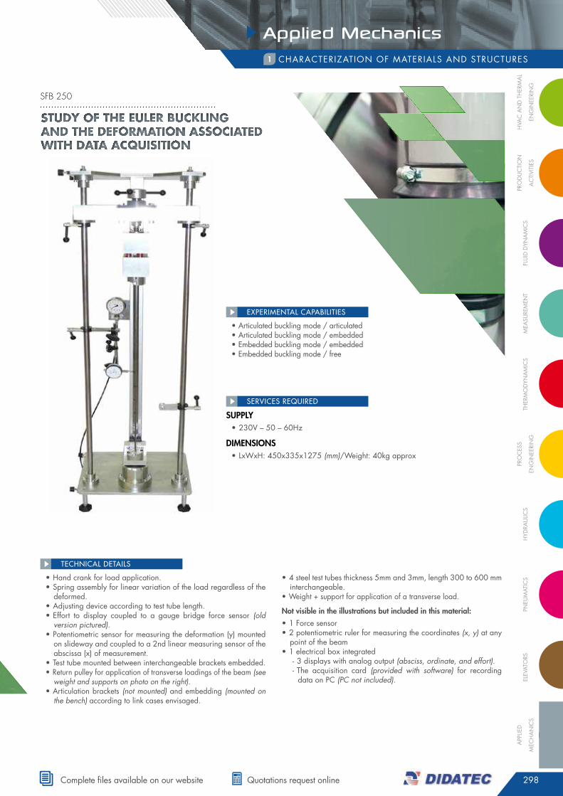
characTeriZaTiOn Of maTeriaLs and sTrucTures1
• hand crank for load application.• spring assembly for linear variation of the load regardless of the
deformed.• adjusting device according to test tube length.• effort to display coupled to a gauge bridge force sensor (old
version pictured).• potentiometric sensor for measuring the deformation (y) mounted
on slideway and coupled to a 2nd linear measuring sensor of the abscissa (x) of measurement.
• Test tube mounted between interchangeable brackets embedded.• return pulley for application of transverse loadings of the beam (see
weight and supports on photo on the right).• articulation brackets (not mounted) and embedding (mounted on
the bench) according to link cases envisaged.
• 4 steel test tubes thickness 5mm and 3mm, length 300 to 600 mm interchangeable.
• Weight + support for application of a transverse load.
not visible in the illustrations but included in this material:
• 1 force sensor• 2 potentiometric ruler for measuring the coordinates (x, y) at any
point of the beam• 1 electrical box integrated
- 3 displays with analog output (absciss, ordinate, and effort). - The acquisition card (provided with software) for recording data on pc (PC not included).
TEChNICAL dETAILS
supply• 230V – 50 – 60hz
DiMensions• LxWxh: 450x335x1275 (mm)/Weight: 40kg approx
SERVICES REQUIREd
• articulated buckling mode / articulated• articulated buckling mode / embedded• embedded buckling mode / embedded• embedded buckling mode / free
EXPERIMENTAL CAPABILITIES
Study of the euler buckling and the deformation aSSociated with data acquiSition
sfb 250
299
Applied Mechanics
tel. +33 (0)4 77 10 10 10 • www.didatec-technologie.com
characTeriZaTiOn Of maTeriaLs and sTrucTures1
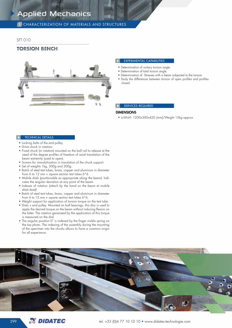
• determination of unitary torsion angle• determination of total torsion angle• determination of stresses with a beam subjected to the torsion• study the differences between torsion of open profiles and profiles
closed
EXPERIMENTAL CAPABILITIES
• Locking bolts of the end pulley.• drive chuck in rotation.• fixed chuck (in rotation) mounted on the ball rail to release at the
need of the degree profiles of freedom of axial translation of the beam extremity (used to open).
• screws for immobilization in translation of the chuck support.• set of weights 1kg, 500g and 200g.• Batch of steel test tubes, brass, copper and aluminum in diameter
from 6 to 12 mm + square section test tubes 6*6.• mobile dials (positionable as appropriate along the beam). indi-
cates the angular deviation at any point of the beam.• indexes of rotation (attach by the hand on the beam at mobile
dials level).• Batch of steel test tubes, brass, copper and aluminum in diameter
from 6 to 12 mm + square section test tubes 6*6.• Weight support for application of torsion torque on the test tube.• dials + end pulley. mounted on ball bearings, this disc is used to
apply the desired torque on the beam without inducing flexion on the latter. The rotation generated by the application of this torque is measured on the dial.
• The angular position 0° is indexed by the finger visible spring on the top photo. The indexing of the assembly during the mounting of the specimen into the chucks allows to have a common origin for all experience.
TEChNICAL dETAILS
DiMensions• LxWxh: 1200x300x420 (mm)/Weight 15kg approx
SERVICES REQUIREd
Torsion bench
sft 010
300
Applied Mechanics
FLU
ID D
YNA
MIC
SM
eASU
reM
eNt
tHer
MO
DYN
AM
ICS
PrO
CeS
S
eNG
INee
rIN
GH
YDrA
ULIC
SPN
eUM
AtIC
SeL
eVAt
OrS
APP
LIeD
MeC
HA
NIC
S
PrO
DU
CtI
ON
AC
tIVI
tIeS
HVA
C A
ND
tH
erM
AL
eNG
INee
rIN
G
complete files available on our website quotations request online
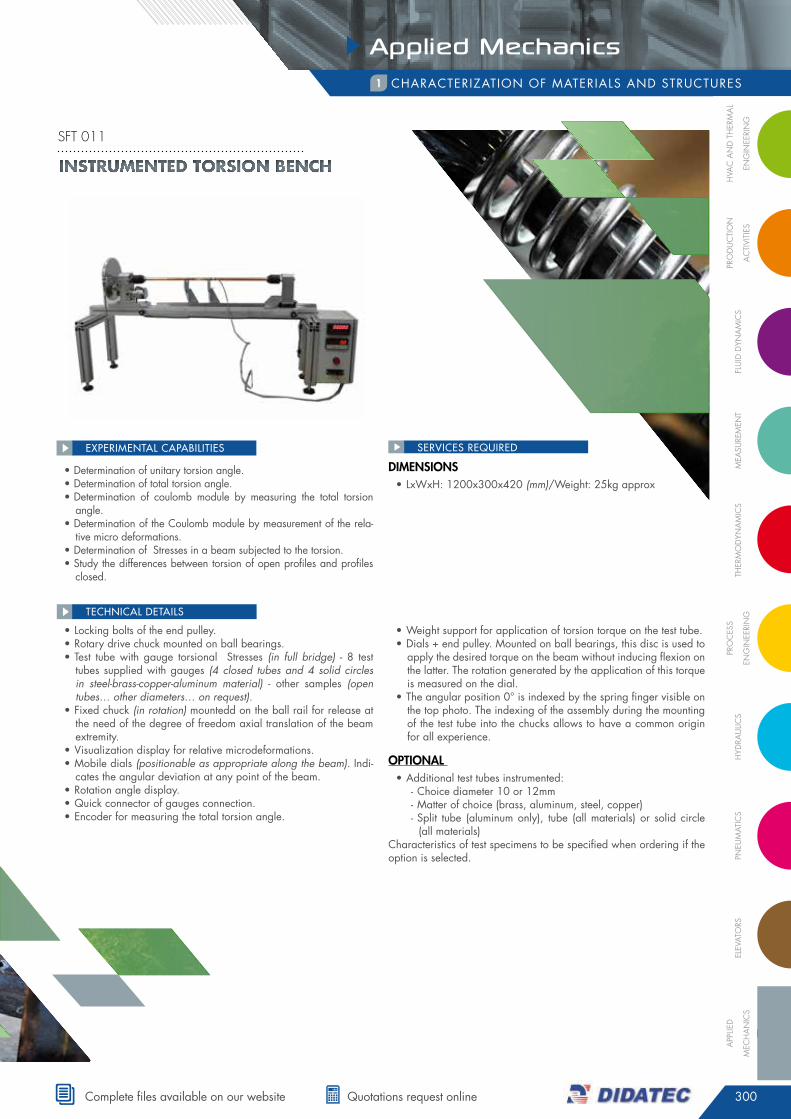
characTeriZaTiOn Of maTeriaLs and sTrucTures1
• determination of unitary torsion angle.• determination of total torsion angle.• determination of coulomb module by measuring the total torsion
angle.• determination of the coulomb module by measurement of the rela-
tive micro deformations.• determination of stresses in a beam subjected to the torsion.• study the differences between torsion of open profiles and profiles
closed.
EXPERIMENTAL CAPABILITIES
• Locking bolts of the end pulley.• rotary drive chuck mounted on ball bearings.• Test tube with gauge torsional stresses (in full bridge) - 8 test
tubes supplied with gauges (4 closed tubes and 4 solid circles in steel-brass-copper-aluminum material) - other samples (open tubes… other diameters… on request).
• fixed chuck (in rotation) mountedd on the ball rail for release at the need of the degree of freedom axial translation of the beam extremity.
• Visualization display for relative microdeformations.• mobile dials (positionable as appropriate along the beam). indi-
cates the angular deviation at any point of the beam.• rotation angle display.• quick connector of gauges connection.• encoder for measuring the total torsion angle.
• Weight support for application of torsion torque on the test tube.• dials + end pulley. mounted on ball bearings, this disc is used to
apply the desired torque on the beam without inducing flexion on the latter. The rotation generated by the application of this torque is measured on the dial.
• The angular position 0° is indexed by the spring finger visible on the top photo. The indexing of the assembly during the mounting of the test tube into the chucks allows to have a common origin for all experience.
optional • additional test tubes instrumented:
- choice diameter 10 or 12mm - matter of choice (brass, aluminum, steel, copper) - split tube (aluminum only), tube (all materials) or solid circle (all materials)
characteristics of test specimens to be specified when ordering if the option is selected.
TEChNICAL dETAILS
DiMensions• LxWxh: 1200x300x420 (mm)/Weight: 25kg approx
SERVICES REQUIREd
Instrumented torsIon bench
sft 011
301
Applied Mechanics
tel. +33 (0)4 77 10 10 10 • www.didatec-technologie.com
characTeriZaTiOn Of maTeriaLs and sTrucTures1
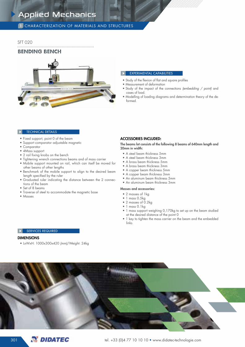
• study of the flexion of flat and square profiles• measurement of deformation• study of the impact of the connections (embedding / point) and
cases of load.• modelling of loading diagrams and determination theory of the de-
formed.
EXPERIMENTAL CAPABILITIES
• fixed support, point 0 of the beam• support comparator adjustable magnetic • comparator• 4mass support• 2 rail fixing knobs on the bench• Tightening wrench connections beams and of mass carrier• mobile support mounted on rail, which can itself be moved for
other beams of other lengths• Benchmark of the mobile support to align to the desired beam
length specified by the ruler• graduated ruler indicating the distance between the 2 connec-
tions of the beam• set of 8 beams• Traverse of steel to accommodate the magnetic base• masses
accessories incluDeD:the beams lot consists of the following 8 beams of 640mm length and 20mm in width:
• a steel beam thickness 5mm• a steel beam thickness 3mm• a brass beam thickness 5mm• a brass beam thickness 3mm• a copper beam thickness 5mm• a copper beam thickness 3mm• an aluminum beam thickness 5mm• an aluminum beam thickness 3mm
Masses and accessories:
• 2 masses of 1kg• 1 mass 0.5kg• 2 masses of 0.2kg• 1 mass 0.1kg• 1 mass support weighing 0,170kg to set up on the beam studied
at the desired distance of the point 0• 1 key to tighten the mass carrier on the beam and the embedded
links
TEChNICAL dETAILS
DiMensions• LxWxh: 1000x300x420 (mm)/Weight: 24kg
SERVICES REQUIREd
BENDING BENCH
sft 020
302
Applied Mechanics
FLU
ID D
YNA
MIC
SM
eASU
reM
eNt
tHer
MO
DYN
AM
ICS
PrO
CeS
S
eNG
INee
rIN
GH
YDrA
ULIC
SPN
eUM
AtIC
SeL
eVAt
OrS
APP
LIeD
MeC
HA
NIC
S
PrO
DU
CtI
ON
AC
tIVI
tIeS
HVA
C A
ND
tH
erM
AL
eNG
INee
rIN
G
complete files available on our website quotations request online
characTeriZaTiOn Of maTeriaLs and sTrucTures1
• study of the profiles flexion• measurement of deformation• study of the impact of the links (embedding / point) and the cases
of load.• modelling of loading diagrams and determination theory of the de-
formations.• measuring of microdeformations• comparing theoretical and experimental model
EXPERIMENTAL CAPABILITIES
• 2 comparators supports with comparator.• 3 adjustable brackets along the beam to be characterized / en-
able the creation of point or embedded links.• 2 weight brackets positioned as appropriate along the beam to
be characterized..• electrical box integrated 1 display relative microdeformations as
well as a quick connection for extensometer gauges.• set of weights 1kg, 500g and 200g.• assortment of 8 test tubes in steel, brass, copper and aluminum,
equipped with extensometer gauges for the flexion.
TEChNICAL dETAILS
DiMensions• LxWxh: 1000x300x600 (mm)/Weight: 35kg
DiMensions• LxWxh: 1000x300x420 (mm)/Weight: 25kg approx
SERVICES REQUIREd
SERVICES REQUIREd
• determination of the shear force in a beam• determination of the bending moment
EXPERIMENTAL CAPABILITIES
• structure of the determination bench of shear and bending mo-ment in a beam - realized of anodized aluminum profiles - 4 feet dampers.
• rigid Beam (at the view of the efforts implemented) - articulated (2 degrees of freedom to the articulation - almost zero friction) to allow measurement of shear forces and bending moments in a cross section beam.
• position of the articulation of the beam at 1/3 of the total length of the beam
• 2 end supports reproducing the links «point» at the ends of the beam-position of the manually adjustable supports along the chassis.
• point loads (from 1 to 3) composed of 1 weight bracket + addi-tional weight (12 weight of 1N and 9 weight of 5N - 20N max per support).
• upper dynamometer intended to measure the shear force in the beam.
• Lower dynamometer (action on the lever arm) intented for mea-suring the bending moment in the considered section
• Threaded thumb wheel (manual nut) of the alignment setting of the 2 beam sections (by action on the dynamometer support) - threaded thumb wheel not visible in this illustration
• graduated ruler to determine the position of the point charges• storage case of accessories (not visible on the following illustration).
TEChNICAL dETAILS
Instrumented BendInG BenCH
sft 021
Study bench of bending momentS and Shear forceS in a beam
sft 022
303
Applied Mechanics
tel. +33 (0)4 77 10 10 10 • www.didatec-technologie.com
characTeriZaTiOn Of maTeriaLs and sTrucTures1
• experimental verification of the hypothesis of the normal stresses• experimental verification of the hypothesis of the shear stresses• experimental verification of the hypothesis of composition of the
stresses• comparison the results obtained for different materials.
EXPERIMENTAL CAPABILITIES
structure• The bench is equipped with an anodized aluminum structure.• in the central part, a mast ensures the embedding function of one of
the ends of the test tube (embedding obtained by pinching).• a circular plateau is secured to the other end of the test tube by
pinching.• This plateau allows to realize the different cases of the test tube
loading, and measuring the deformations of the latter.• a mobile weight support ensures the plateau loading on its peri-
phery.• a balancing device eliminates the shear forces applied onto the test
piece, in countering the effect of the weight of the plateau as well as the different components attached on this latter.
• The solicitation can evolve in pure bending, at pure torsion, through all the intermediate states of compound solicitations.
• a comparator of magnetic base allows to measure the displace-ments periphery of the disc.
• The integration positions of loading and of the comparator are mar-ked every 15°.
test tuBes• 1 set of 4 cylindrical test pieces of diameter 12mm comes with the
bench for the beam deformation study: • 1 in brass, 1 in copper, 1 in aluminum, 1 in steel.• 1 set of 4 cylindrical test pieces 12mm diameter equipped with
extensometer gauges for stresses analysis is provided: - 1 in brass, 1 in copper, 1 in aluminum, 1 in steel.
optionsTest tubes batches can be provided on request (contact us).
TEChNICAL dETAILS
DiMensions• LxWxh: 400x400x400 (mm)/Weight: 25kg approx
SERVICES REQUIREd
Verification of the StreSSeS hypotheSiS
sft 100
304
Applied Mechanics
FLU
ID D
YNA
MIC
SM
eASU
reM
eNt
tHer
MO
DYN
AM
ICS
PrO
CeS
S
eNG
INee
rIN
GH
YDrA
ULIC
SPN
eUM
AtIC
SeL
eVAt
OrS
APP
LIeD
MeC
HA
NIC
S
PrO
DU
CtI
ON
AC
tIVI
tIeS
HVA
C A
ND
tH
erM
AL
eNG
INee
rIN
G
complete files available on our website quotations request online
characTeriZaTiOn Of maTeriaLs and sTrucTures1
• determination of the unitary torsion angle• determination of total torsion angle• study of the flat profiles bending• comparison of theoretical and practical approaches of the defor-
mations• measurement of the deformed (in bending and torsion)
EXPERIMENTAL CAPABILITIES
• structure aluminum on 4 feet adjustable for perfect stability.• fixed support equipped with rotatable mobile chuck.• Translating mobile support equipped with the fixed chuck.• comparison on adjustable magnetic support, for measuring the
bending beam deformation.• dial + end pulley for measuring the torsion.• Locking bolts at the angular position 0° of the end pulley for tor-
sion testing.• Weight support for application of torsion torque on the test tube.• Load support for bending tests on round test tubes.• Load support for bending tests on flat test tubes.• set of weights 1kg, 500g, 200g and 100g.
• assortment of 8 test tubes in steel, brass, copper and aluminum for torsion (diameters 6 and 8 mm), and 8 test tubes of rectangu-lar section of steel, aluminum, copper and brass for bending tests.
• mobile ruler for determination of the length of the test tube.• steel support for maintaining the magnetic base.• mobile dials (positionable along the beam) indicating the angular
deviation at any point of the beam.• Torsion measuring needles on movable disk to be placed on
round Ø6 & 8mm.• a tightening screw a of the mobile support rail.• screw B for tightening of the mobile support rail.• support test tube in flexion for point connection or embedding.
TEChNICAL dETAILS
DiMensions• LxWxh: 1200x300x420 (mm)/Weight: 25kg approx
SERVICES REQUIREd
BENDING BENCH - SIMPLE TORSION
sft 300
305
Applied Mechanics
tel. +33 (0)4 77 10 10 10 • www.didatec-technologie.com
characTeriZaTiOn Of maTeriaLs and sTrucTures1
• determination of unitary torsion angle• determination of total torsion angle• study of the flat profiles bending• Bending depending on the case of bi-embedded links, embedded
/ point, bi point)• comparing theoretical and practical approaches of the deformed• measurement of the deformation (in bending and torsion)• Overlay of the solicitations (torsion / bending pure / simple ben-
ding).• comparison of the deformed in pure or simple bending
EXPERIMENTAL CAPABILITIES
structure• Benchtop anodized aluminum chassis.• 4 adjustable feet.• a measurement instrumentation supported by the system.
siMple BenDing test area• 2 adjustable spacing supports.• possibility on these 2 supports to produce a point support or em-
bedded.• 1 position adjustable weight carrier.• 1 mobile comparator support + comparator to 0.01mm for mea-
suring of the deformation.
test area pure torsion anD torsion / flexion coM-poseD:• allows to realize the pure torsion tests, or of torsion / flexion
composed.• 2 chucks for fixation of the ends of the beam:
- chuck a fixed in rotation around its axis mounted on a support with 2 axes of freedom.
- chuck B, mobile in rotation around its axis, mounted on ball bearings.
• Torsional moment created by applying weight on a pulley integral of the chuck a
• measure of the overall torsional angle on graduated dial• 2 annexes graduated supports positionable along the beam al-
lowing to highlight the concept of unitary angle of torsion.• a localized bending moment at the end of the beam can be ap-
plied at the chuck B level.• a shear force inducing a bending moment can also be applied
at the chuck B level.• The design of the system makes completely independent the loads
inducing the moments of torsion, of bending or shear force.• all loads are applied by using specific weight of 100g, 200g,
500g and 1kg.• The deformed measurements are accurate to 0.01 rad closely
and 0.01mm.
test tuBes • 1 lot of test tube of various materials for bending tests (rectangular
section) / materials: aluminum, copper, steel / different dimen-sions.
• 1 batch of test tube of varied materials for torsion tests, or solici-tation composed (circular section) / materials: aluminum, copper, steel / tube or round / different lengths / diameters.
TEChNICAL dETAILS
DiMensions• LxWxh: 1200x500x600 (mm)/Weight: 55kg approx
SERVICES REQUIREd
BENDING BENCH - TorsIoN sImplE or CompouND
sft 350
306
Applied Mechanics
FLU
ID D
YNA
MIC
SM
eASU
reM
eNt
tHer
MO
DYN
AM
ICS
PrO
CeS
S
eNG
INee
rIN
GH
YDrA
ULIC
SPN
eUM
AtIC
SeL
eVAt
OrS
APP
LIeD
MeC
HA
NIC
S
PrO
DU
CtI
ON
AC
tIVI
tIeS
HVA
C A
ND
tH
erM
AL
eNG
INee
rIN
G
complete files available on our website quotations request online
SERVICES REQUIREd
characTeriZaTiOn Of maTeriaLs and sTrucTures1
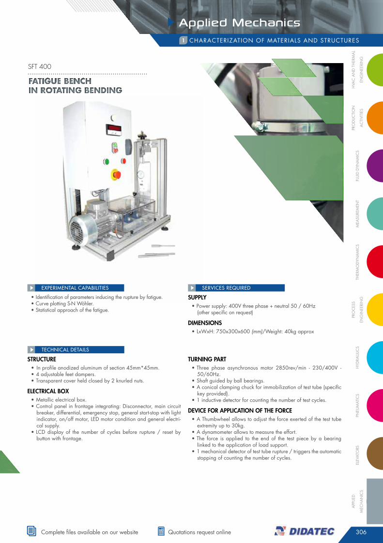
• identification of parameters inducing the rupture by fatigue.• curve plotting s-n Wöhler.• statistical approach of the fatigue.
EXPERIMENTAL CAPABILITIES
structure• in profile anodized aluminum of section 45mm*45mm. • 4 adjustable feet dampers.• Transparent cover held closed by 2 knurled nuts.
electrical Box• metallic electrical box.• control panel in frontage integrating: disconnector, main circuit
breaker, differential, emergency stop, general start-stop with light indicator, on/off motor, Led motor condition and general electri-cal supply.
• Lcd display of the number of cycles before rupture / reset by button with frontage.
turning part• Three phase asynchronous motor 2850rev/min - 230/400V -
50/60hz.• shaft guided by ball bearings.• a conical clamping chuck for immobilization of test tube (specific
key provided).• 1 inductive detector for counting the number of test cycles.
Device for application of tHe force• a Thumbwheel allows to adjust the force exerted of the test tube
extremity up to 30kg.• a dynamometer allows to measure the effort.• The force is applied to the end of the test piece by a bearing
linked to the application of load support.• 1 mechanical detector of test tube rupture / triggers the automatic
stopping of counting the number of cycles.
TEChNICAL dETAILS
supply• power supply: 400V three phase + neutral 50 / 60hz
(other specific on request)
DiMensions• LxWxh: 750x300x600 (mm)/Weight: 40kg approx
Fatigue bench in rotating bending
sft 400

307
Applied Mechanics
tel. +33 (0)4 77 10 10 10 • www.didatec-technologie.com
characTeriZaTiOn Of maTeriaLs and sTrucTures1
• study of the behavior of different materials subjected to the torsion / elastic domain
• study of the behavior of different materials subjected to the torsion / plastic domain until rupture
• determination of the coulomb module / comparison with theore-tical approach
EXPERIMENTAL CAPABILITIES
structure anD electric Box• chassis in anodized aluminum profiles• 4 adjustable feet dampers• electrical box incorporating a general isolator and an emergency
stop• On / off switch general with status Led• startup switch of motor• angle display with analogue output (left display)• Torque display with analogue output (right display).
geareD Motor • motor 230V single phase - 0.18kW - 50/60hz - 1500rev/min• double reducer of total reduction ratio i = 1/1600• Torque limiter calibrated at 200nm
instruMentation :• angle measurement: encoder of resolution 3600 ppt• Torque measurement: force sensor capacity of 500dan mounted
on swiveled torque arm
• displays of torque and angle (CF electrical box) with analog out-put to the acquisition card.
• multichannel acquisition card for acquisition on the pc (not sup-plied) via usB port (cable supplied)
• software compatible with acquisition card for data recording (compatible excel export) variable period of sampling, conditio-ning calculation formulas of acquisition signals and graphic plots printable
test tuBes • 1 set of 10 torsion test tubes (2 * steel 42CD4 , 2 in steel E24 ,
2* aluminum 2* brass and 2* copper)
TEChNICAL dETAILS
supply• Power supply: 230V mono phase + neutral 50 / 60Hz
(other specific on request)• pc (not supplied) - Windows Xp
DiMensions• LxWxh: 900x500x600 (mm)/Weight: 60kg approx
SERVICES REQUIREd
Motorized torsion bench 200nM
sft 600
308
Applied Mechanics
FLU
ID D
YNA
MIC
SM
eASU
reM
eNt
tHer
MO
DYN
AM
ICS
PrO
CeS
S
eNG
INee
rIN
GH
YDrA
ULIC
SPN
eUM
AtIC
SeL
eVAt
OrS
APP
LIeD
MeC
HA
NIC
S
PrO
DU
CtI
ON
AC
tIVI
tIeS
HVA
C A
ND
tH
erM
AL
eNG
INee
rIN
G
complete files available on our website quotations request online
SERVICES REQUIREd
characTeriZaTiOn Of maTeriaLs and sTrucTures1
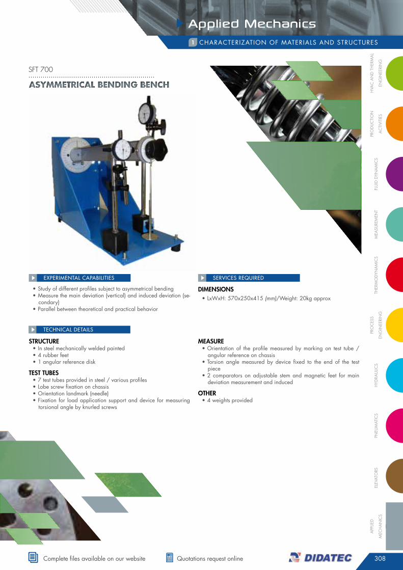
• study of different profiles subject to asymmetrical bending• measure the main deviation (vertical) and induced deviation (se-
condary)• parallel between theoretical and practical behavior
EXPERIMENTAL CAPABILITIES
structure• in steel mechanically welded painted• 4 rubber feet• 1 angular reference disk
test tuBes• 7 test tubes provided in steel / various profiles• Lobe screw fixation on chassis• Orientation landmark (needle)• fixation for load application support and device for measuring
torsional angle by knurled screws
Measure• Orientation of the profile measured by marking on test tube /
angular reference on chassis• Torsion angle measured by device fixed to the end of the test
piece• 2 comparators on adjustable stem and magnetic feet for main
deviation measurement and induced
otHer• 4 weights provided
TEChNICAL dETAILS
DiMensions• LxWxh: 570x250x415 (mm)/Weight: 20kg approx
AsymmetricAl bending bench
sft 700
309
Applied Mechanics
tel. +33 (0)4 77 10 10 10 • www.didatec-technologie.com
characTeriZaTiOn Of maTeriaLs and sTrucTures1
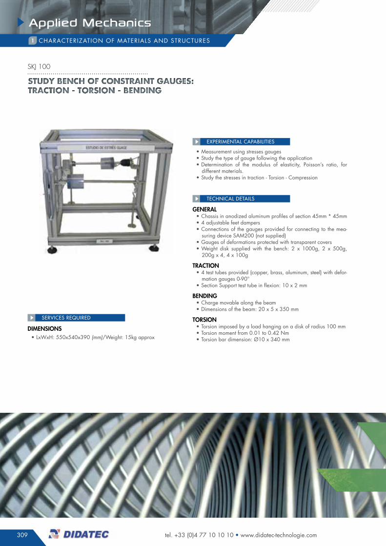
• measurement using stresses gauges• study the type of gauge following the application• determination of the modulus of elasticity, poisson’s ratio, for
different materials.• study the stresses in traction - Torsion - compression
EXPERIMENTAL CAPABILITIES
general• chassis in anodized aluminum profiles of section 45mm * 45mm• 4 adjustable feet dampers• connections of the gauges provided for connecting to the mea-
suring device sam200 (not supplied)• gauges of deformations protected with transparent covers• Weight disk supplied with the bench: 2 x 1000g, 2 x 500g,
200g x 4, 4 x 100g
traction • 4 test tubes provided (copper, brass, aluminum, steel) with defor-
mation gauges 0-90°• section support test tube in flexion: 10 x 2 mm
BenDing• charge movable along the beam• dimensions of the beam: 20 x 5 x 350 mm
torsion• Torsion imposed by a load hanging on a disk of radius 100 mm• Torsion moment from 0.01 to 0.42 nm• Torsion bar dimension: Ø10 x 340 mm
TEChNICAL dETAILS
DiMensions• LxWxh: 550x540x390 (mm)/Weight: 15kg approx
SERVICES REQUIREd
STUDY BENCH OF CONSTRAINT GAUGES: TRACTION - TORSION - BENDING
skj 100
310
Applied Mechanics
FLU
ID D
YNA
MIC
SM
eASU
reM
eNt
tHer
MO
DYN
AM
ICS
PrO
CeS
S
eNG
INee
rIN
GH
YDrA
ULIC
SPN
eUM
AtIC
SeL
eVAt
OrS
APP
LIeD
MeC
HA
NIC
S
PrO
DU
CtI
ON
AC
tIVI
tIeS
HVA
C A
ND
tH
erM
AL
eNG
INee
rIN
G
complete files available on our website quotations request online
SERVICES REQUIREd
characTeriZaTiOn Of maTeriaLs and sTrucTures1
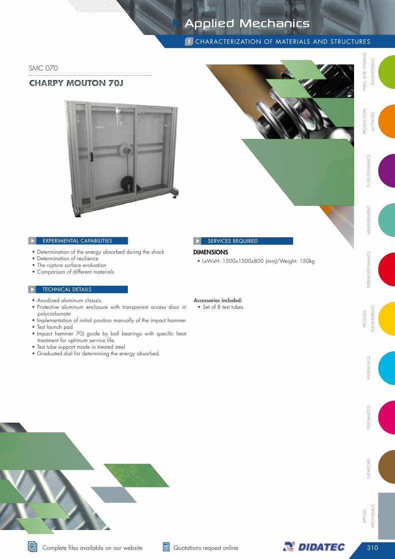
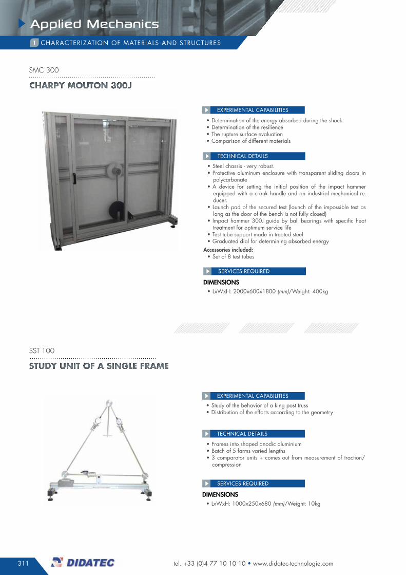
• determination of the energy absorbed during the shock• determination of resilience• The rupture surface evaluation• comparison of different materials
EXPERIMENTAL CAPABILITIES
• anodized aluminum chassis.• protective aluminum enclosure with transparent access door in
polycarbonate • implementation of initial position manually of the impact hammer• Test launch pad• impact hammer 70J guide by ball bearings with specific heat
treatment for optimum service life.• Test tube support made in treated steel• graduated dial for determining the energy absorbed.
accessories included:• set of 8 test tubes
TEChNICAL dETAILS
DiMensions• LxWxh: 1500x1500x800 (mm)/Weight: 150kg
Charpy Mouton 70J
smc 070
311
Applied Mechanics
tel. +33 (0)4 77 10 10 10 • www.didatec-technologie.com
SERVICES REQUIREd
characTeriZaTiOn Of maTeriaLs and sTrucTures1
• determination of the energy absorbed during the shock• determination of the resilience• The rupture surface evaluation• comparison of different materials
• study of the behavior of a king post truss• distribution of the efforts according to the geometry
EXPERIMENTAL CAPABILITIES
EXPERIMENTAL CAPABILITIES
• steel chassis - very robust.• protective aluminum enclosure with transparent sliding doors in
polycarbonate • a device for setting the initial position of the impact hammer
equipped with a crank handle and an industrial mechanical re-ducer.
• Launch pad of the secured test (launch of the impossible test as long as the door of the bench is not fully closed)
• impact hammer 300J guide by ball bearings with specific heat treatment for optimum service life
• Test tube support made in treated steel• graduated dial for determining absorbed energy
accessories included:• set of 8 test tubes
• frames into shaped anodic aluminium • Batch of 5 farms varied lengths• 3 comparator units + comes out from measurement of traction/
compression
TEChNICAL dETAILS
TEChNICAL dETAILS
DiMensions• LxWxh: 2000x600x1800 (mm)/Weight: 400kg
DiMensions• LxWxh: 1000x250x680 (mm)/Weight: 10kg
sst 100
SERVICES REQUIREd
Charpy Mouton 300J
smc 300
Study unit of a Single frame
312
Applied Mechanics
FLU
ID D
YNA
MIC
SM
eASU
reM
eNt
tHer
MO
DYN
AM
ICS
PrO
CeS
S
eNG
INee
rIN
GH
YDrA
ULIC
SPN
eUM
AtIC
SeL
eVAt
OrS
APP
LIeD
MeC
HA
NIC
S
PrO
DU
CtI
ON
AC
tIVI
tIeS
HVA
C A
ND
tH
erM
AL
eNG
INee
rIN
G
complete files available on our website quotations request online
SERVICES REQUIREd
characTeriZaTiOn Of maTeriaLs and sTrucTures1
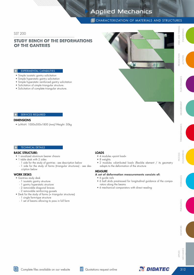
• simple isostatic gantry solicitation• simple hyperstatic gantry solicitation• simple hyperstatic reinforced gantry solicitation• solicitation of simple triangular structure.• solicitation of complete triangular structure.
EXPERIMENTAL CAPABILITIES
Basic structure:• 1 anodized aluminum bearer chassis • 1 table desk with 2 sides
- 1 side for the study of gantries - see description below - 1 side for the study of farms (triangular structures) - see des-cription below
Work Desks• gantries study desk
- 1 isostatic gantry structure - 1 gantry hyperstatic structure - 2 removable diagonal braces - 2 removable reinforcing gussets
• desk for the study of farms (= triangular structures) - 1 single farm-type structure - 1 set of beams allowing to pass in full farm
loaDs• 4 modules «point load»• 8 weights• 2 modules «distributed load» (flexible element / its geometry
adapts to the deformation of the structure
Measure A set of deformation measurements consists of:• 6 guide rails• 6 ball skids prestressed for longitudinal guidance of the compa-
rators along the beams • 6 mechanical comparators with direct reading
TEChNICAL dETAILS
DiMensions• LxWxh: 1000x500x1800 (mm)/Weight: 50kg
STUDY BENCH OF THE DEFORMATIONS OF THE GANTRIES
sst 200
313
Applied Mechanics
tel. +33 (0)4 77 10 10 10 • www.didatec-technologie.com
SERVICES REQUIREd
characTeriZaTiOn Of maTeriaLs and sTrucTures1
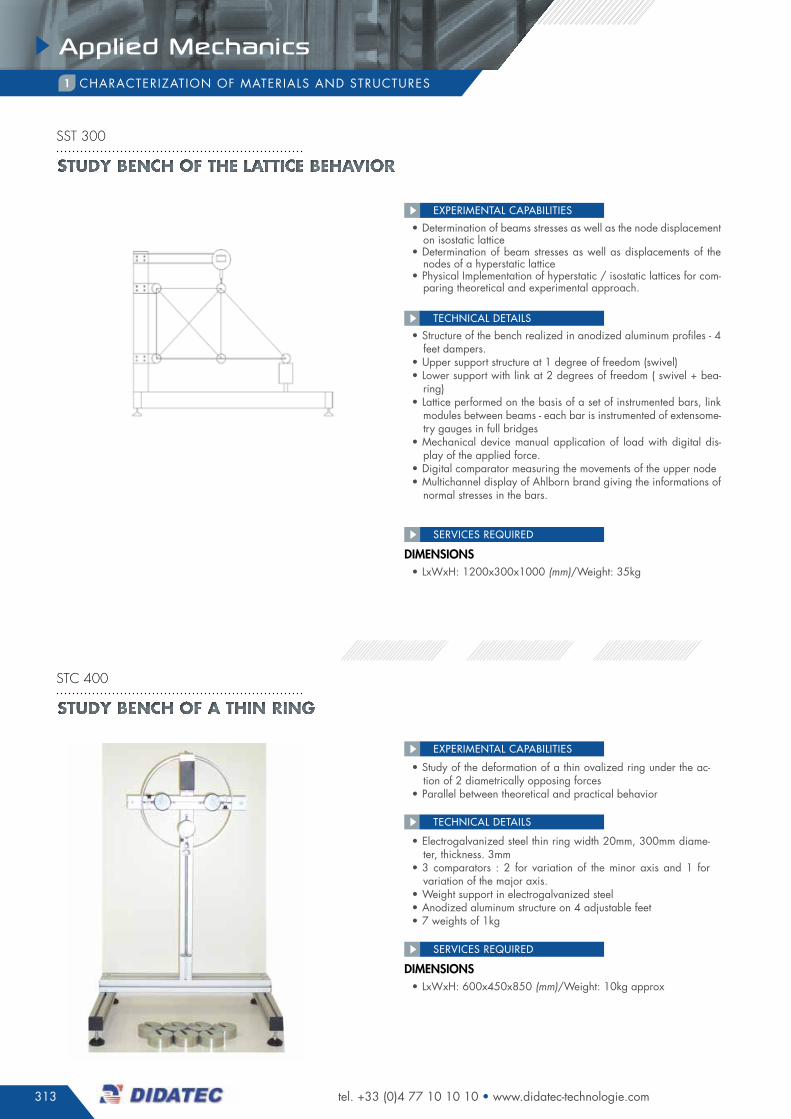
• determination of beams stresses as well as the node displacement on isostatic lattice
• determination of beam stresses as well as displacements of the nodes of a hyperstatic lattice
• physical implementation of hyperstatic / isostatic lattices for com-paring theoretical and experimental approach.
• study of the deformation of a thin ovalized ring under the ac-tion of 2 diametrically opposing forces
• parallel between theoretical and practical behavior
EXPERIMENTAL CAPABILITIES
EXPERIMENTAL CAPABILITIES
• structure of the bench realized in anodized aluminum profiles - 4 feet dampers.
• upper support structure at 1 degree of freedom (swivel)• Lower support with link at 2 degrees of freedom ( swivel + bea-
ring)• Lattice performed on the basis of a set of instrumented bars, link
modules between beams - each bar is instrumented of extensome-try gauges in full bridges
• mechanical device manual application of load with digital dis-play of the applied force.
• digital comparator measuring the movements of the upper node• multichannel display of ahlborn brand giving the informations of
normal stresses in the bars.
• electrogalvanized steel thin ring width 20mm, 300mm diame-ter, thickness. 3mm
• 3 comparators : 2 for variation of the minor axis and 1 for variation of the major axis.
• Weight support in electrogalvanized steel• anodized aluminum structure on 4 adjustable feet• 7 weights of 1kg
TEChNICAL dETAILS
TEChNICAL dETAILS
DiMensions• LxWxh: 1200x300x1000 (mm)/Weight: 35kg
DiMensions• LxWxh: 600x450x850 (mm)/Weight: 10kg approx
SERVICES REQUIREd
Study bench of the lattice behavior
sst 300
Study bench of a thin ring
stc 400
314
Applied Mechanics
FLU
ID D
YNA
MIC
SM
eASU
reM
eNt
tHer
MO
DYN
AM
ICS
PrO
CeS
S
eNG
INee
rIN
GH
YDrA
ULIC
SPN
eUM
AtIC
SeL
eVAt
OrS
APP
LIeD
MeC
HA
NIC
S
PrO
DU
CtI
ON
AC
tIVI
tIeS
HVA
C A
ND
tH
erM
AL
eNG
INee
rIN
G
complete files available on our website quotations request online
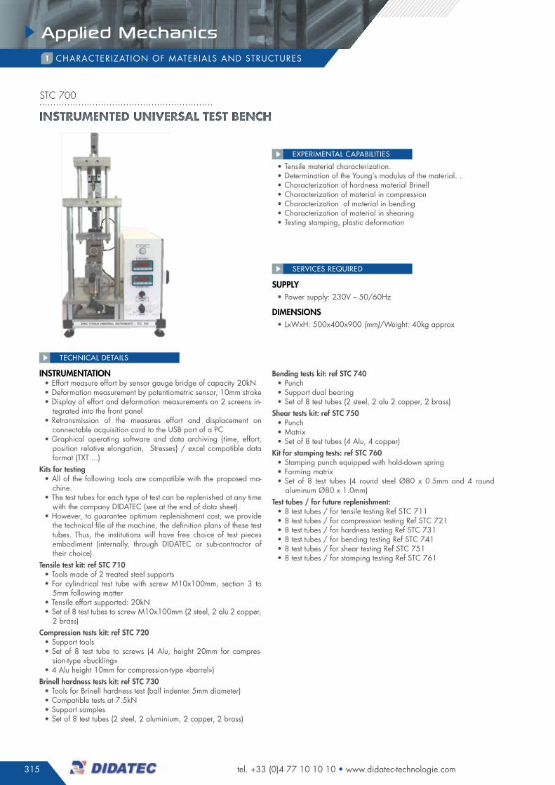
characTeriZaTiOn Of maTeriaLs and sTrucTures1
• Tensile material characterization.• determination of the Young’s modulus of the material.• characterization of hardness material Brinell• characterization of material in compression• characterization of material in bending• characterization of material in shearing• stamping testing, plastic deformation
EXPERIMENTAL CAPABILITIES
• comparator for measuring relative displacements of the fixed part of the tools and the mobile part
• presetting nut of the spacing between the movable part and the fixed part of the tool according to the test tube to be tested, in order to facilitate the adjustments
• integration tensile test tubes area• integration area of the test tubes and tools requiring a compres-
sion work (hardness, shear, compression, stamping, bending)• dynamometric ring (the measurement is made in deformation: a
calibration tableau gives the correspondence between the values of deformation of the measured ring and the applied load
• crank handle allowing to apply a progressively load
options
kits for testing • The test tubes corresponding to each type of test can be repleni-
shed at any time with the company didaTec (see at the end of data sheet).
• But in order to guarantee optimum replenishment cost, we provide in the technical file of the machine, the plans of definition of these test tubes. Thus, the institutions will have free choice of test pieces embodiment (internally, through didaTec or sub-contractor of their choice).
• Tensile test kit: ref sTc 610 / included in sTc 600• Tools made of 2 treated steel supports • for cylindrical test piece with screw m10x100mm, section 3 to
5mm following matter• Tensile force supported: 20kn• set of 8 test tubes to screw m10x100mm (2 steel, 2 alu, 2 cop-
per, 2 brass)
compression tests kit: ref sTc 620 / included in sTc 600• support tools• set of 8 test tubes (4 alu, height 20mm for compression-type «buc-
kling»• 4 alu height 10mm for compression-type «barrel»)
Brinell hardness tests kit: ref stc 630 / included in stc 600• Tools for Brinell hardness test (ball indenter 5mm diameter)• compatible tests at 7.5kn• support samples• set of 8 test tubes (2 steel, 2 alu, 2 copper, 2 brass)
Bending tests kit: ref stc 640 / included in stc 600• punch• support dual bearing• set of 8 test tubes (2 steel, 2 alu 2 copper, 2 brass)
shear tests kit: ref stc 650 / included in stc 600• punch• matrix• set of 8 test tubes (4 alu, 4 copper)
kit for stamping tests: ref sTc 660/ included in sTc 600 • stamping punch equipped with hold-down spring • forming matrix• set of 8 test tubes (4 round steel Ø80 x 0.5mm and 4 round
aluminum Ø80 x 1.0mm)test tubes / for future replenishment:• 8 test tubes / for tensile testing ref sTc 611• 8 test tubes / for compression testing ref sTc 621• 8 test tubes / for hardness testing ref sTc 631• 8 test tubes / for bending testing ref sTc 641• 8 test tubes / for shear testing ref sTc 651• 8 test tubes / for stamping testing ref sTc 661
TEChNICAL dETAILS
DiMensions• LxWxh: 500x400x900 (mm)/Weight: 38kg
SERVICES REQUIREd
Universal test bench
stc 600
315
Applied Mechanics
tel. +33 (0)4 77 10 10 10 • www.didatec-technologie.com
characTeriZaTiOn Of maTeriaLs and sTrucTures1
stc 700
• Tensile material characterization.• determination of the Young’s modulus of the material. .• characterization of hardness material Brinell • characterization of material in compression• characterization of material in bending• characterization of material in shearing• Testing stamping, plastic deformation
EXPERIMENTAL CAPABILITIES
TEChNICAL dETAILS
supply• power supply: 230V – 50/60hz
DiMensions• LxWxh: 500x400x900 (mm)/Weight: 40kg approx
SERVICES REQUIREd
instruMentation • effort measure effort by sensor gauge bridge of capacity 20kn• deformation measurement by potentiometric sensor, 10mm stroke• display of effort and deformation measurements on 2 screens in-
tegrated into the front panel• retransmission of the measures effort and displacement on
connectable acquisition card to the usB port of a pc• graphical operating software and data archiving {time, effort,
position relative elongation, stresses} / excel compatible data format (TXT ...)
kits for testing • all of the following tools are compatible with the proposed ma-
chine.• The test tubes for each type of test can be replenished at any time
with the company didaTec (see at the end of data sheet).• however, to guarantee optimum replenishment cost, we provide
the technical file of the machine, the definition plans of these test tubes. Thus, the institutions will have free choice of test pieces embodiment (internally, through didaTec or sub-contractor of their choice).
tensile test kit: ref stc 710 • Tools made of 2 treated steel supports • for cylindrical test tube with screw m10x100mm, section 3 to
5mm following matter• Tensile effort supported: 20kn• set of 8 test tubes to screw m10x100mm (2 steel, 2 alu 2 copper,
2 brass)compression tests kit: ref stc 720 • support tools• set of 8 test tube to screws (4 alu, height 20mm for compres-
sion-type «buckling»• 4 alu height 10mm for compression-type «barrel»)
Brinell hardness tests kit: ref stc 730 • Tools for Brinell hardness test (ball indenter 5mm diameter)• compatible tests at 7.5kn• support samples• set of 8 test tubes (2 steel, 2 aluminium, 2 copper, 2 brass)
Bending tests kit: ref stc 740 • punch• support dual bearing• set of 8 test tubes (2 steel, 2 alu 2 copper, 2 brass)
shear tests kit: ref stc 750 • punch• matrix• set of 8 test tubes (4 alu, 4 copper)
kit for stamping tests: ref stc 760 • stamping punch equipped with hold-down spring • forming matrix• set of 8 test tubes (4 round steel Ø80 x 0.5mm and 4 round
aluminum Ø80 x 1.0mm)test tubes / for future replenishment:• 8 test tubes / for tensile testing ref sTc 711• 8 test tubes / for compression testing ref sTc 721• 8 test tubes / for hardness testing ref sTc 731• 8 test tubes / for bending testing ref sTc 741• 8 test tubes / for shear testing ref sTc 751• 8 test tubes / for stamping testing ref sTc 761
Instrumented unIversal test bench
316
Applied Mechanics
FLU
ID D
YNA
MIC
SM
eASU
reM
eNt
tHer
MO
DYN
AM
ICS
PrO
CeS
S
eNG
INee
rIN
GH
YDrA
ULIC
SPN
eUM
AtIC
SeL
eVAt
OrS
APP
LIeD
MeC
HA
NIC
S
PrO
DU
CtI
ON
AC
tIVI
tIeS
HVA
C A
ND
tH
erM
AL
eNG
INee
rIN
G
complete files available on our website quotations request online
eLecTricaL and cOnTrOL sYsTem2
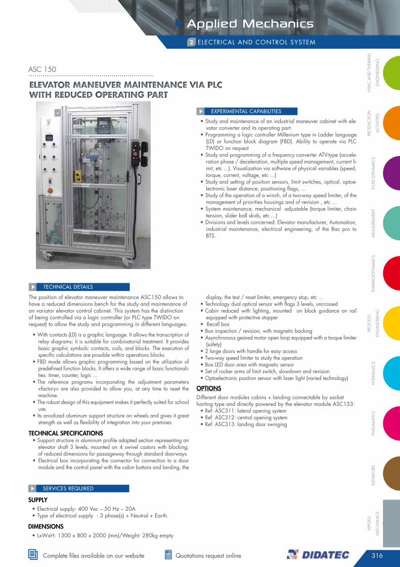
asc 150
• study and maintenance of an industrial maneuver cabinet with ele-vator converter and its operating part.
• programming a logic controller millenium type in Ladder language (Ld) or function block diagram (fBd). ability to operate via pLc TWidO on request
• study and programming of a frequency converter aTV-type (accele-ration phase / deceleration, multiple speed management, current li-mit, etc ...). Visualization via software of physical variables (speed, torque, current, voltage, etc ...)
• study and setting of position sensors, limit switches, optical, optoe-lectronic laser distance, positioning flags, ...
• study of the operation of a winch, of a two-way speed limiter, of the management of priorities housings and of revision , etc ...
• system maintenance, mechanical adjustable (torque limiter, chain tension, slider ball skids, etc ...)
• divisions and levels concerned: elevator manufacturer, automation, industrial maintenance, electrical engineering, of the Bac pro to BTs.
EXPERIMENTAL CAPABILITIES
The position of elevator maneuver maintenance asc150 allows to have a reduced dimensions bench for the study and maintenance of an variator elevator control cabinet. This system has the distinction of being controlled via a logic controller (or pLc type TWidO on request) to allow the study and programming in different languages:
• With contacts (Ld) is a graphic language. it allows the transcription of relay diagrams; it is suitable for combinatorial treatment. it provides basic graphic symbols: contacts, coils, and blocks. The execution of specific calculations are possible within operations blocks.
• fBd mode allows graphic programming based on the utilization of predefined function blocks. it offers a wide range of basic functionali-ties: timer, counter, logic ...
• The reference programs incorporating the adjustment parameters «factory» are also provided to allow you, at any time to reset the machine.
• The robust design of this equipment makes it perfectly suited for school use.
• its anodized aluminum support structure on wheels and gives it great strength as well as flexibility of integration into your premises
tecHnical specifications • support structure in aluminum profile adapted section representing an
elevator shaft 3 levels, mounted on 4 swivel castors with blocking, of reduced dimensions for passageway through standard doorways
• electrical box incorporating the connector for connection to a door module and the control panel with the cabin buttons and landing, the
display, the test / reset limiter, emergency stop, etc ...• Technology dual optical sensor with flags 3 levels, uncrossed• cabin reduced with lighting, mounted on block guidance on rail
equipped with protective stopper• recall box• Box inspection / revision, with magnetic backing• asynchronous geared motor open loop equipped with a torque limiter
(safety)• 2 large doors with handle for easy access• Two-way speed limiter to study the operation• Box Led door area with magnetic sensor• set of rocker arms of limit switch, slowdown and revision• Optoelectronic position sensor with laser light (varied technology)
optionsdifferent door modules cabins + landing connectable by socket harting type and directly powered by the elevator module asc153:• ref: asc311: lateral opening system• ref: asc312: central opening system• ref: asc313: landing door swinging
TEChNICAL dETAILS
supply• electrical supply: 400 Vac – 50 hz – 20a • Type of electrical supply : 3 phase(s) + neutral + earth.
DiMensions• LxWxh: 1300 x 800 x 2000 (mm)/Weight: 280kg empty
SERVICES REQUIREd
ElEvator manEuvEr maintEnancE via Plc with rEducEd oPErating Part
317
Applied Mechanics
tel. +33 (0)4 77 10 10 10 • www.didatec-technologie.com
mechanicaL OsciLLaTOrs3
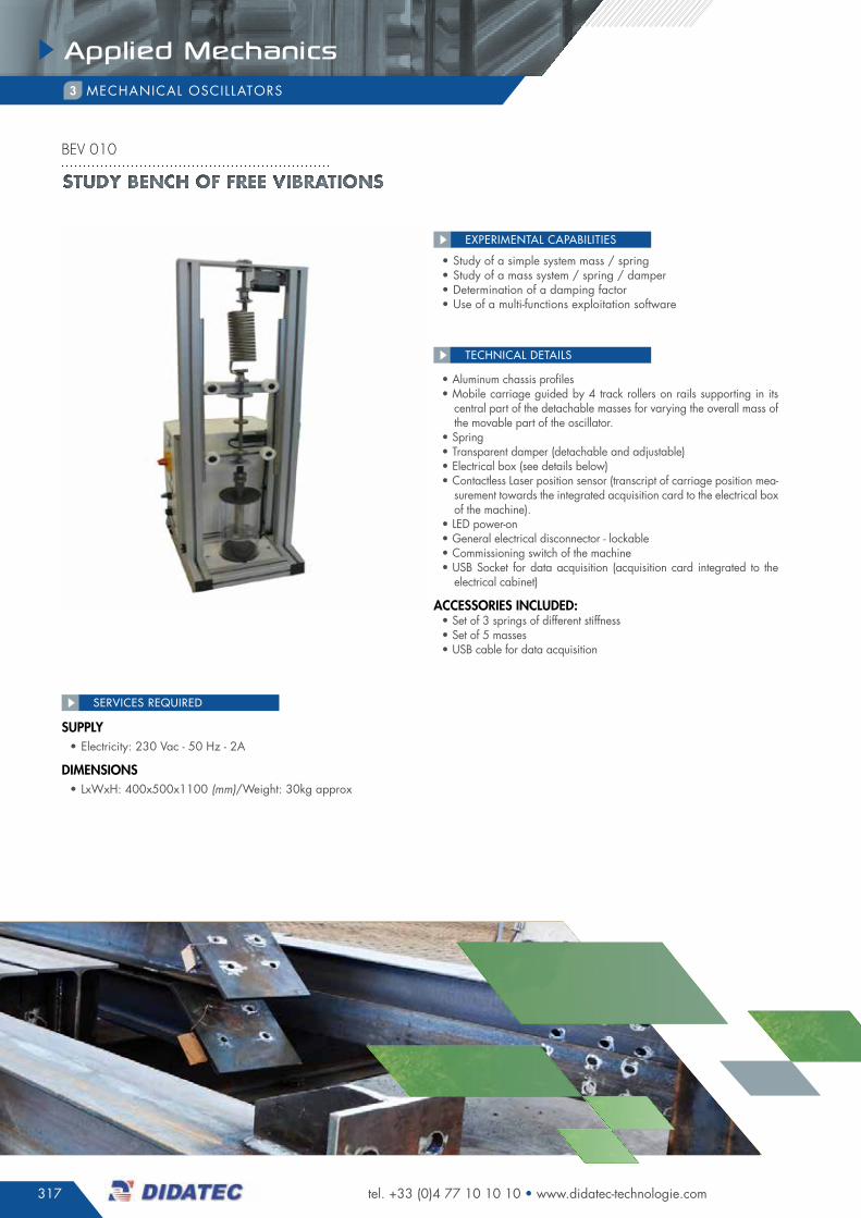
• study of a simple system mass / spring • study of a mass system / spring / damper• determination of a damping factor• use of a multi-functions exploitation software
EXPERIMENTAL CAPABILITIES
• aluminum chassis profiles• mobile carriage guided by 4 track rollers on rails supporting in its
central part of the detachable masses for varying the overall mass of the movable part of the oscillator.
• spring• Transparent damper (detachable and adjustable)• electrical box (see details below)• contactless Laser position sensor (transcript of carriage position mea-
surement towards the integrated acquisition card to the electrical box of the machine).
• Led power-on • general electrical disconnector - lockable• commissioning switch of the machine• usB socket for data acquisition (acquisition card integrated to the
electrical cabinet)
accessories incluDeD:• set of 3 springs of different stiffness• set of 5 masses• usB cable for data acquisition
TEChNICAL dETAILS
supply• electricity: 230 Vac - 50 hz - 2a
DiMensions• LxWxh: 400x500x1100 (mm)/Weight: 30kg approx
SERVICES REQUIREd
Study bench of free vibrationS
bev 010
318
Applied Mechanics
FLU
ID D
YNA
MIC
SM
eASU
reM
eNt
tHer
MO
DYN
AM
ICS
PrO
CeS
S
eNG
INee
rIN
GH
YDrA
ULIC
SPN
eUM
AtIC
SeL
eVAt
OrS
APP
LIeD
MeC
HA
NIC
S
PrO
DU
CtI
ON
AC
tIVI
tIeS
HVA
C A
ND
tH
erM
AL
eNG
INee
rIN
G
complete files available on our website quotations request online
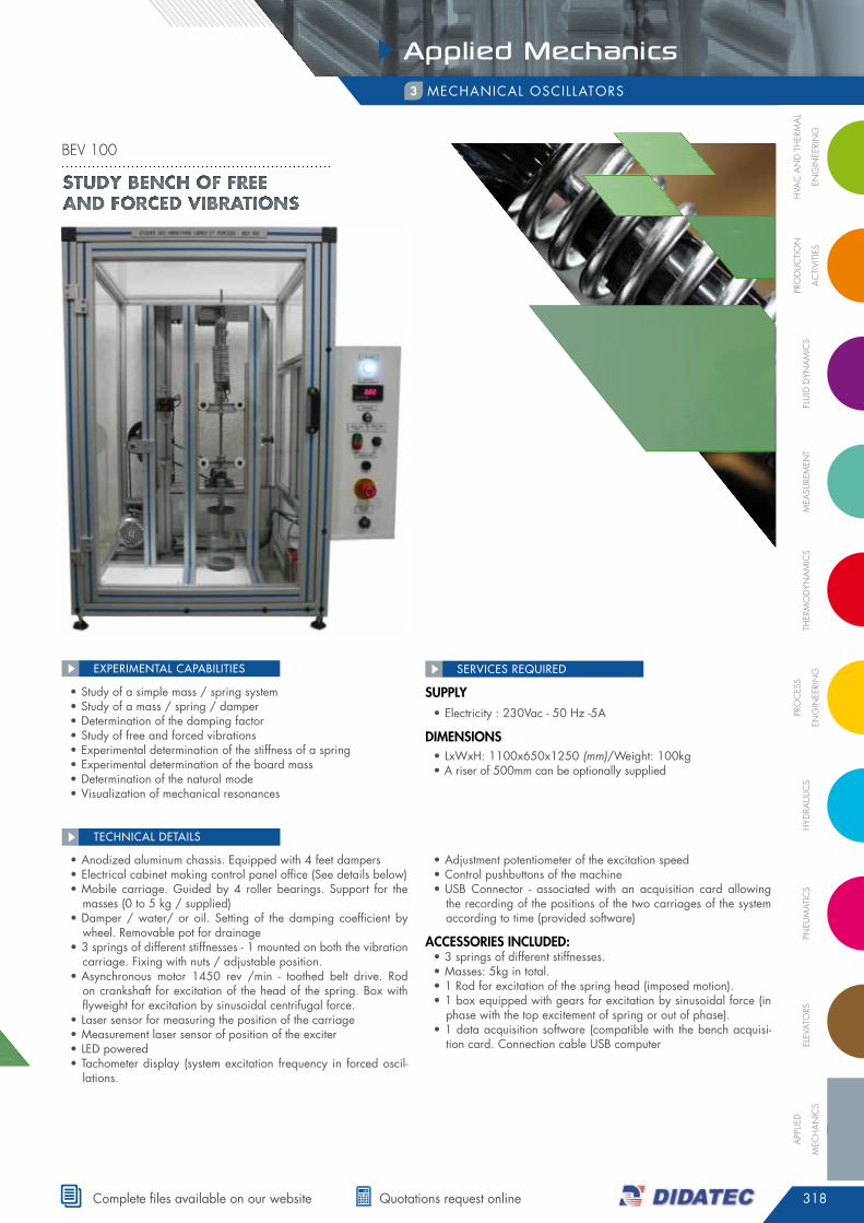
mechanicaL OsciLLaTOrs3
• anodized aluminum chassis. equipped with 4 feet dampers• electrical cabinet making control panel office (see details below)• mobile carriage. guided by 4 roller bearings. support for the
masses (0 to 5 kg / supplied)• damper / water/ or oil. setting of the damping coefficient by
wheel. removable pot for drainage• 3 springs of different stiffnesses - 1 mounted on both the vibration
carriage. fixing with nuts / adjustable position.• asynchronous motor 1450 rev /min - toothed belt drive. rod
on crankshaft for excitation of the head of the spring. Box with flyweight for excitation by sinusoidal centrifugal force.
• Laser sensor for measuring the position of the carriage• measurement laser sensor of position of the exciter• Led powered• Tachometer display (system excitation frequency in forced oscil-
lations.
• adjustment potentiometer of the excitation speed• control pushbuttons of the machine• usB connector - associated with an acquisition card allowing
the recording of the positions of the two carriages of the system according to time (provided software)
accessories incluDeD:• 3 springs of different stiffnesses.• masses: 5kg in total.• 1 rod for excitation of the spring head (imposed motion).• 1 box equipped with gears for excitation by sinusoidal force (in
phase with the top excitement of spring or out of phase).• 1 data acquisition software (compatible with the bench acquisi-
tion card. connection cable usB computer
TEChNICAL dETAILS
supply• electricity : 230Vac - 50 hz -5a
DiMensions• LxWxh: 1100x650x1250 (mm)/Weight: 100kg• a riser of 500mm can be optionally supplied
SERVICES REQUIREd
• study of a simple mass / spring system• study of a mass / spring / damper• determination of the damping factor• study of free and forced vibrations• experimental determination of the stiffness of a spring• experimental determination of the board mass• determination of the natural mode• Visualization of mechanical resonances
EXPERIMENTAL CAPABILITIES
Study bench of free and forced vibrationS
bev 100
319
Applied Mechanics
tel. +33 (0)4 77 10 10 10 • www.didatec-technologie.com
mechanicaL OsciLLaTOrs3
• static balancing concept• comparison of the balancing effects / static unbalance / dyna-
mic .• effect of weight distribution along a shaft• measurement of dynamic loads on the bearings as a function of
the angle of the shaft
EXPERIMENTAL CAPABILITIES
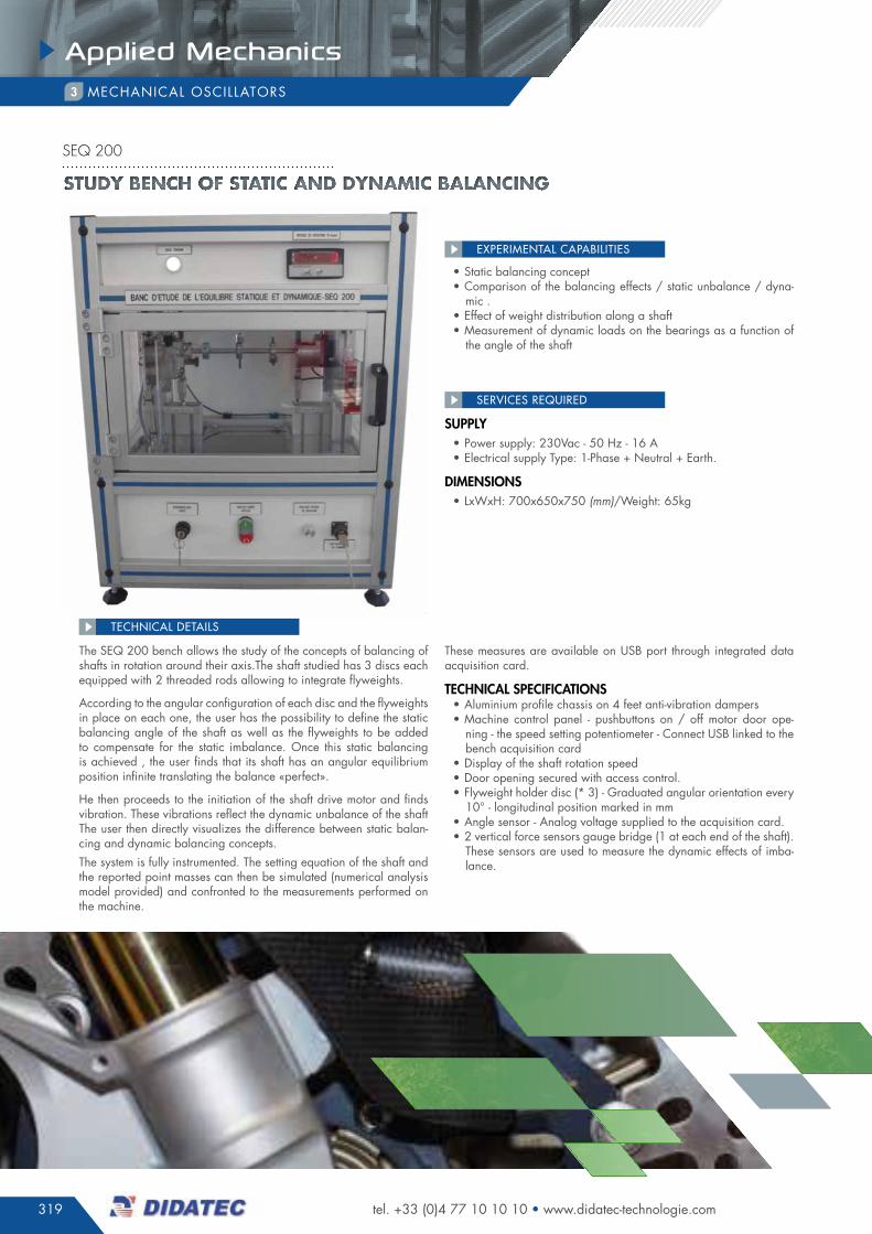
The seq 200 bench allows the study of the concepts of balancing of shafts in rotation around their axis.The shaft studied has 3 discs each equipped with 2 threaded rods allowing to integrate flyweights.
according to the angular configuration of each disc and the flyweights in place on each one, the user has the possibility to define the static balancing angle of the shaft as well as the flyweights to be added to compensate for the static imbalance. Once this static balancing is achieved , the user finds that its shaft has an angular equilibrium position infinite translating the balance «perfect».
he then proceeds to the initiation of the shaft drive motor and finds vibration. These vibrations reflect the dynamic unbalance of the shaftThe user then directly visualizes the difference between static balan-cing and dynamic balancing concepts.The system is fully instrumented. The setting equation of the shaft and the reported point masses can then be simulated (numerical analysis model provided) and confronted to the measurements performed on the machine.
These measures are available on usB port through integrated data acquisition card.
tecHnical specifications• aluminium profile chassis on 4 feet anti-vibration dampers• machine control panel - pushbuttons on / off motor door ope-
ning - the speed setting potentiometer - connect usB linked to the bench acquisition card
• display of the shaft rotation speed• door opening secured with access control.• flyweight holder disc (* 3) - graduated angular orientation every
10° - longitudinal position marked in mm• angle sensor - analog voltage supplied to the acquisition card.• 2 vertical force sensors gauge bridge (1 at each end of the shaft).
These sensors are used to measure the dynamic effects of imba-lance.
TEChNICAL dETAILS
supply• power supply: 230Vac - 50 hz - 16 a• electrical supply Type: 1-phase + neutral + earth.
DiMensions• LxWxh: 700x650x750 (mm)/Weight: 65kg
SERVICES REQUIREd
Study bench of Static and dynamic balancing
seq 200
320
Applied Mechanics
FLU
ID D
YNA
MIC
SM
eASU
reM
eNt
tHer
MO
DYN
AM
ICS
PrO
CeS
S
eNG
INee
rIN
GH
YDrA
ULIC
SPN
eUM
AtIC
SeL
eVAt
OrS
APP
LIeD
MeC
HA
NIC
S
PrO
DU
CtI
ON
AC
tIVI
tIeS
HVA
C A
ND
tH
erM
AL
eNG
INee
rIN
G
complete files available on our website quotations request online
mechanicaL OsciLLaTOrs3
• experimental determination of the stiffness of a spring• experimental determination of the mass of a system with spring• Variations analysis of amortization coefficients on the system be-
havior• normal modes vibration analysis of beam in bending • identification of the different modes of forced oscillation• implementation equation and analyzing the behavior of a pen-
dulum weighing.
EXPERIMENTAL CAPABILITIES
• mobile chassis made of aluminum profiles on 4 wheels braked• control panel incorporating the full control pushbuttons system inclu-
ding 2 usB connectors and jack 3.5 ‘’ for data acquisition on the pc (accelerometer, angle of the pendulum, linear position of the device mass / spring / damper) and generation of vibrations on the electro-magnetic exciter (from audio source on pc - pc not included)
• pendulum weighing - adjustable masses (100 and 200g)• analog angle sensor - available signal on acquisition card.• Vibrating beam in console to study heavy beam or spring beam be-
havior with or without additive mass (measured by accelerometer connected to an acquisition card).
• Vibrating beam - used with or without electromagnetic exciter (for set-ting forced vibration from 35 to 3000 hz approximately). associated mobile supports to create point and embedded links (modification of the limit conditions of the beam) - measured by accelerometer connec-ted to an acquisition card).
• device mass / spring / damper: spring (3 springs of different stiffness provided) - mobile carriage guided with mass support (5kg of masses and supplied in 0,5kg to 1kg) - adjustable damper with knob - Linear position sensor without contact - laser (signal available on the acqui-sition card)
accessories incluDeD:• set of bending bars of different lengths, materials and thickness• set of 5 kg of mass fractionated in 0.5kg and 1kg • set of 3 springs of different stiffness• instrumentation: angle sensor, laser position sensor and accelerometer
with acquisition cards.
TEChNICAL dETAILS
supply• electricity: 230 V - 50 hz - 5a
DiMensions• LxWxh: 1600x800x1950 (mm)/Weight: 200kg approx
SERVICES REQUIREd
Study bench of the oScillationS and vibrationS
svb 100
321
Applied Mechanics
tel. +33 (0)4 77 10 10 10 • www.didatec-technologie.com
mechanicaL OsciLLaTOrs3
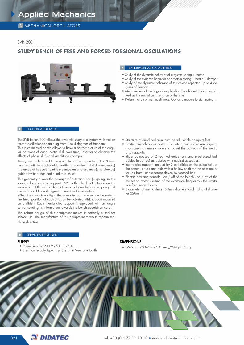
• study of the dynamic behavior of a system spring + inertia• study of the dynamic behavior of a system spring + inertia + damper• study of the dynamic behavior of the device repeated up to 4 de-
grees of freedom• measurement of the angular amplitudes of each inertia, damping as
well as the excitation in function of the time• determination of inertia, stiffness, coulomb module torsion spring ...
EXPERIMENTAL CAPABILITIES
The sVB bench 200 allows the dynamic study of a system with free or forced oscillations containing from 1 to 4 degrees of freedom.This instrumented bench allows to have a perfect picture of the angu-lar positions of each inertia disk over time, in order to observe the effects of phase shifts and amplitude changes.The system is designed to be scalable and incorporate of 1 to 3 iner-tia discs, with fully adjustable positions. each inertial disk (removable) is pierced at its center and is mounted on a rotary axis (also pierced) guided by bearings and fixed to a chuck.This geometry allows the passage of a torsion bar (= spring) in the various discs and disc supports. When the chuck is tightened on the torsion bar of the inertia disc acts punctually on the torsion spring and creates an additional degree of freedom to the system.When the chuck is not tight, the mass disc has no effect on the system.the linear position of each disc can be adjusted (disk support mounted on a slider). each inertia disc support is equipped with an angle sensor sending its information towards the bench acquisition card.The robust design of this equipment makes it perfectly suited for school use. The manufacture of this equipment meets european ma-chine directive
• structure of anodized aluminum on adjustable dampers feet• exciter: asynchronous motor - excitation cam - idler arm - spring
- tachometric sensor - sliders to adjust the position of the inertia disc supports.
• slider composed of 2 rectified guide rails and prestressed ball guides (play-free) associated with each disc support.
• inertia disc support - guided by 2 ball slides on the guide rails of the bench - chuck and axis with a hollow shaft for the passage of torsion bars - angle sensor driven by toothed belt
• electric box and console - on / off of the bench - on / off of the excitation motor - setting of the excitation frequency - the excita-tion frequency display
• 2 diameter of inertia discs 150mm diameter and 1 disc of diame-ter 228mm.
TEChNICAL dETAILS
supply• power supply: 230 V - 50 hz - 5 a• electrical supply type: 1 phase (s) + neutral + earth.
DiMensions• LxWxh: 1700x600x750 (mm)/Weight: 75kg
SERVICES REQUIREd
Study bench of free and forced torSional oScillationS
svb 200

322
Applied Mechanics
FLU
ID D
YNA
MIC
SM
eASU
reM
eNt
tHer
MO
DYN
AM
ICS
PrO
CeS
S
eNG
INee
rIN
GH
YDrA
ULIC
SPN
eUM
AtIC
SeL
eVAt
OrS
APP
LIeD
MeC
HA
NIC
S
PrO
DU
CtI
ON
AC
tIVI
tIeS
HVA
C A
ND
tH
erM
AL
eNG
INee
rIN
G
complete files available on our website quotations request online
mechanicaL OsciLLaTOrs3
• study of the dynamic behavior of a system spring + inertia• study of the dynamic behavior of a system inertia + spring +
damper• study of the dynamic behavior of a system spring + inertia +
spring + damper• measurement of the frequency + amplitudes at the level of inertia• determination of the damping coefficient, inertia, stiffness, cou-
lomb module of torsion spring ...
EXPERIMENTAL CAPABILITIES
The sVB 300 bench allows the study of free torsional oscillations of a torsion spring system / inertial disk / damperThe system configuration can be modulated by simply changing the spring stiffness (change in length and / or material and / or diame-ter), the inertia and damping applied.The inertia disc and its support are drilled in the center to allow pas-sage of the torsion bar (torsion spring). When the mandrel associated with the inertia is clamped on the torsion bar, the inertia disc is oc-casionally on the torsion spring and creates an additional degree of freedom to the system.When the chuck is not tight, the mass disc has no effect on the system.The position of the disc can be adjusted with the vertical slideway of the bench. The angular position of the inertia disc is measured at any time by means of an angle sensor returning its information towards the bench acquisition card.The damper consists of a pot containing a liquid (water or oil).The relative position of the fixed and rotating parts of the damper define the damping coefficient of the system.The time of damping is applied at the end of the spring.The system allows to cover the following configurations: {spring-iner-tia} ; {spring - inertia - spring - damper}; {spring - inertia - shock}The robust design of this equipment makes it perfectly suited for school use.The manufacture of this equipment meets european machine directive
• anodized aluminum chassis - 4 feet adjustable dampers• Box of electrical supply - disconnect switch - sensor supply - acqui-
sition card• support of high end of the torsion spring, adjustable in height for
adjustment of the length of the torsion bar (= adjustment of the spring stiffness) - fixing by 2 manual thumbwheels
• inertia disc: 2 interchangeable inertia discs supplied with diameter 150mm and 228mm - mountable on a support guided in rotation by 2 ball bearings. rotation axis pierced at its center for passage of the torsion bar - vertically adjustable position by the use of 2 manual thumbwheels and a slideway - 1 angular position sensor of the inertia disc connected to the acquisition card- association of inertia to the spring by manual tightening chuck
• Viscous damper - 1 fixed part - 1 moving part (drive in rotation by manual tightening chuck - adjustable damping coefficient to cover my domains «under damping», «critical» and «over-damping»
• springs: 6 bars of torsions in steel / aluminum / copper and va-rious diameters ranging from 4 to 6mm for performing different tests (different stiffnesses).
TEChNICAL dETAILS
supply• power supply: 230Vac - 50hz - 2a• electrical supply type: 1phase + neutral + earth.
DiMensions• LxWxh: 500x300x1300 (mm)/Weight: 20kg approx
SERVICES REQUIREd
Study bench of free torSional oScillationS
svb 300
323
Applied Mechanics
tel. +33 (0)4 77 10 10 10 • www.didatec-technologie.com
mechanicaL OsciLLaTOrs3
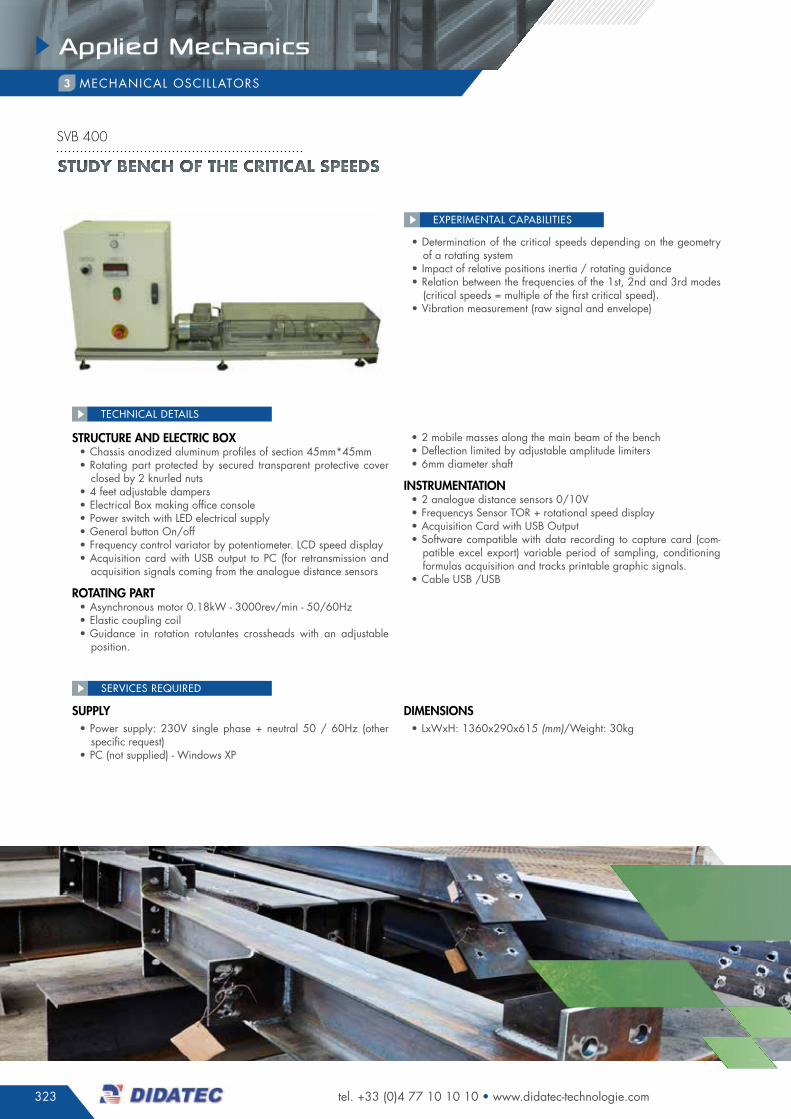
• determination of the critical speeds depending on the geometry of a rotating system
• impact of relative positions inertia / rotating guidance• relation between the frequencies of the 1st, 2nd and 3rd modes
(critical speeds = multiple of the first critical speed).• Vibration measurement (raw signal and envelope)
EXPERIMENTAL CAPABILITIES
structure anD electric Box• chassis anodized aluminum profiles of section 45mm*45mm• rotating part protected by secured transparent protective cover
closed by 2 knurled nuts• 4 feet adjustable dampers• electrical Box making office console • power switch with Led electrical supply• general button On/off • frequency control variator by potentiometer. Lcd speed display• acquisition card with usB output to pc (for retransmission and
acquisition signals coming from the analogue distance sensors
rotating part• asynchronous motor 0.18kW - 3000rev/min - 50/60hz• elastic coupling coil• guidance in rotation rotulantes crossheads with an adjustable
position.
• 2 mobile masses along the main beam of the bench• deflection limited by adjustable amplitude limiters• 6mm diameter shaft
instruMentation• 2 analogue distance sensors 0/10V• frequencys sensor TOr + rotational speed display• acquisition card with usB Output• software compatible with data recording to capture card (com-
patible excel export) variable period of sampling, conditioning formulas acquisition and tracks printable graphic signals.
• cable usB /usB
TEChNICAL dETAILS
supply• power supply: 230V single phase + neutral 50 / 60hz (other
specific request)• pc (not supplied) - Windows Xp
DiMensions• LxWxh: 1360x290x615 (mm)/Weight: 30kg
SERVICES REQUIREd
Study bench of the critical SpeedS
svb 400
324
Applied Mechanics
FLU
ID D
YNA
MIC
SM
eASU
reM
eNt
tHer
MO
DYN
AM
ICS
PrO
CeS
S
eNG
INee
rIN
GH
YDrA
ULIC
SPN
eUM
AtIC
SeL
eVAt
OrS
APP
LIeD
MeC
HA
NIC
S
PrO
DU
CtI
ON
AC
tIVI
tIeS
HVA
C A
ND
tH
erM
AL
eNG
INee
rIN
G
complete files available on our website quotations request online
sOLid sTaTe phYsics and mechanism4
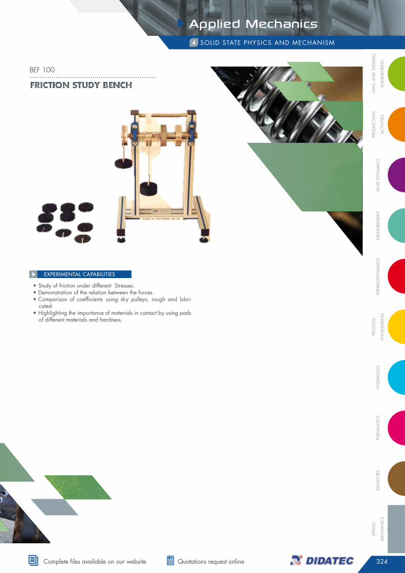
• study of friction under different stresses.• demonstration of the relation between the forces.• comparison of coefficients using dry pulleys, rough and lubri-
cated.• highlighting the importance of materials in contact by using pads
of different materials and hardness.
EXPERIMENTAL CAPABILITIES
Friction study bench
bef 100

325
Applied Mechanics
tel. +33 (0)4 77 10 10 10 • www.didatec-technologie.com
sOLid sTaTe phYsics and mechanism4
• study of friction in the case of sliding movement and of rotation.• determine the relation between normal force and frictional force• compare the friction between the dry bodies and the lubricated
bodies• determining the friction coefficient for different materials of diffe-
rent hardness
EXPERIMENTAL CAPABILITIES
• Bench Bef200 modular in aluminum profile consists of three in-terlocking parts each equipped with handles. The ensemble is mounted on 4 feet adherents: presented mounting plane / cy-linder
• part 1: apparatus for friction measurement and application of a mass on the pad for the two types test plane / plane and plane / cylinder
• dynamometer 50n capacity, accuracy 0.02n with peak function for measuring the maximum static friction, direct reading of the value of the force: running on aa Battery or mains 220Vac
• set of masses (total 5kg: 4*1kg + 1*0.5kg + 2*0.2kg + 1*0.1kg) for establishing the normal force on the pad
• support weight to apply vertical force on the pad in position in the pad support
• support pad, fits under the rod of the weight support for holding the chosen pad against the reference surface
• Translational guidance unit to transcribe to the dynamometer the
horizontal force exerted• part 2: removable apparatus for friction tests in the sliding plane
on the cylinder in treated steel, equipped with a removable lubri-cating bin and a crank handle
• part 3: apparatus for friction tests in the case of plane sliding on a plane (treated steel plate), equipped with a mobile carriage with handle. as part of this type of test, part 2 is removed prior inserting part 1 on part 3
• Lot 12 friction pads, Ø45mm, thickness. 5mm
accessories incluDeD• Lot 12 friction pads of different materials and hardness (steel,
aluminum, bronze, ferodo, cast iron, plastic) with a pad holder• 1 degreasing product• 1 oil bottle• 1 batch of wipes for the cleaning
TEChNICAL dETAILS
DiMensions• LxWxh: 800x600x500 (mm)/Weight: 20kg approx
SERVICES REQUIREd
Study bench of the plane frictionS /plane (Sliding) and plane / cylinder (bearing)
bef 200

326
Applied Mechanics
FLU
ID D
YNA
MIC
SM
eASU
reM
eNt
tHer
MO
DYN
AM
ICS
PrO
CeS
S
eNG
INee
rIN
GH
YDrA
ULIC
SPN
eUM
AtIC
SeL
eVAt
OrS
APP
LIeD
MeC
HA
NIC
S
PrO
DU
CtI
ON
AC
tIVI
tIeS
HVA
C A
ND
tH
erM
AL
eNG
INee
rIN
G
complete files available on our website quotations request online
sOLid sTaTe phYsics and mechanism4
• aluminum anodized chassis benchtop on 4 feet.• protection of rotating parts: transparent; controlled access door
by safety switch (stopping the motorization in case of opening).• drive motor mounted on pendulum for torque measurement. shaft
equipped with with a spindle; driving of pieces to be characte-rized by interconnection.
• counter spindle: driven in rotation by interconnection on the pieces to be characterized. adjustable counter-spindle height to adapt to the geometry of the pieces to be characterized.
• Tachometer sensor with information sent towards data acquisition card.
• a torque sensor with strain gauges• electrical box: circuit breakers, main switch, power supply, motor
variator, conditioner for gauge bridge sensor, usB acquisition card national instrument for temporal measurement of torque and acceleration signals (provided software).
• panel: button power on / general stop, start / stop button mo-tor, pLc allowing to select and manage different operating cycles (alternating cycles, alternating cycles, and acceleration - speed constant-deceleration ...).
accessories incluDeD• 2 full discs 300mm diameter in aluminum thickness 15mm can
be used alone or assembled + 1 steel disc diameter 300mm Thickness 15mm
• 1 steel bar thickness 15mm length 300mm • 1 steel bar thickness 15mm length 300mm incorporating the cy-
lindrical flyweights at the ends.• solid cylinder featuring fixation point to the ends (main axis).• solid cylinder of the same dimensions the cylinder described
above but with radial attachment points.• hollow cylinder of the same dimensions as above.
TEChNICAL dETAILS
supply• electricity: 230 Vac - 50 hz - 4a
DiMensions• LxWxh: 800x600X800 (mm)/Weight: 75kg approx
SERVICES REQUIREd
• characterization and comparison of inertia of different discs and cylinders.
• composition of inertia in the case of cylindrical flyweights (hu-ygens).
• implementation in system equation.• comparison of theoretical approach / measure on the system.
EXPERIMENTAL CAPABILITIES
Study bench of inertia Motorized / inStruMented
bei 200
327
Applied Mechanics
tel. +33 (0)4 77 10 10 10 • www.didatec-technologie.com
sOLid sTaTe phYsics and mechanism4
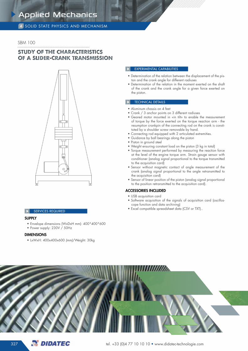
• determination of the relation between the displacement of the pis-ton and the crank angle for different radiuses
• determination of the relation in the moment exerted on the shaft of the crank and the crank angle for a given force exerted on the piston.
EXPERIMENTAL CAPABILITIES
• aluminum chassis on 4 feet• crank / 3 anchor points on 3 different radiuses• geared motor mounted in «in tilt» to enable the measurement
of torque by the force exerted on the torque reaction arm - the resumption crankpin of the connecting rod on the crank is consti-tuted by a shoulder screw removable by hand.
• connecting rod equipped with 2 articulated extremities.• guidance by ball bearings along the piston• piston in ground steel• Weight ensuring constant load on the piston (3 kg in total)• Torque measurement performed by measuring the reaction force
at the level of the engine torque arm. strain gauge sensor with conditioner (analog signal proportional to the torque transmitted to the acquisition card)
• sensor without magnetic contact of angle measurement of the crank (analog signal proportional to the angle retransmitted to the acquisition card)
• sensor of linear position of the piston (analog signal proportional to the position retransmitted to the acquisition card).
accessories incluDeD• usB acquisition card• software acquisition of the signals of acquisition card (oscillos-
cope function and data archiving)• excel compatible spreadsheet data (csV or TXT)..
TEChNICAL dETAILS
supply• envelope dimensions (Wxdxh mm): 400*400*600• power supply: 230V / 50hz
DiMensions• LxWxh: 400x400x600 (mm)/Weight: 30kg
SERVICES REQUIREd
Study of the characteriSticS of a Slider-crank tranSmiSSion
sbm 100
328
Applied Mechanics
FLU
ID D
YNA
MIC
SM
eASU
reM
eNt
tHer
MO
DYN
AM
ICS
PrO
CeS
S
eNG
INee
rIN
GH
YDrA
ULIC
SPN
eUM
AtIC
SeL
eVAt
OrS
APP
LIeD
MeC
HA
NIC
S
PrO
DU
CtI
ON
AC
tIVI
tIeS
HVA
C A
ND
tH
erM
AL
eNG
INee
rIN
G
complete files available on our website quotations request online
sOLid sTaTe phYsics and mechanism4
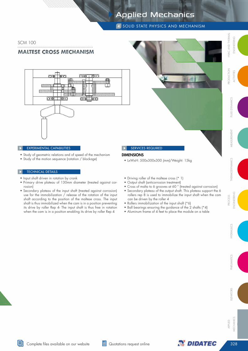
• study of geometric relations and of speed of the mechanism• study of the motion sequence (rotation / blockage)
EXPERIMENTAL CAPABILITIES
• input shaft driven in rotation by crank• primary drive plateau of 130mm diameter (treated against cor-
rosion)• secondary plateau of the input shaft (treated against corrosion)
use for the immobilization / release of the rotation of the input shaft according to the position of the maltese cross. The input shaft is thus immobilized when the cam is in a position preventing its drive by roller rep 4- The input shaft is thus free in rotation when the cam is in a position enabling its drive by roller rep 4
• driving roller of the maltese cross (* 1)• Output shaft (anticorrosion treatment)• cross of malta to 6 grooves at 60 ° (treated against corrosion)• secondary plateau of the output shaft. This plateau support the 6
rollers rep 8 is used to immobilize the input shaft when the cam can be driven by the roller 4
• rollers immobilization of the input shaft (*6)• Ball bearings ensuring the guidance of the 2 shafts (*4)• aluminum frame of 4 feet to place the module on a table
TEChNICAL dETAILS
DiMensions• LxWxh: 500x300x300 (mm)/Weight: 15kg
SERVICES REQUIREd
Maltese cross MechanisM
scm 100
329
Applied Mechanics
tel. +33 (0)4 77 10 10 10 • www.didatec-technologie.com
sOLid sTaTe phYsics and mechanism4
• calibration of measurement relative to the movement of the flyweights• Balancing by successive approaches
EXPERIMENTAL CAPABILITIES
oBjective of tHe application• This support allows rotating a flywheel with flyweights allowing
the unbalance / balance in order to correlate the vibration mea-surements using an external device (not included / contact us) with dynamic data of the system.
tecHnical Description of tHe siD 100 systeM• a drum 3000rev/min• a disc having 4 grooves at 90°• 4 adjustable flyweights on these grooves• supporting structure in polycarbonate with rubber dampers feet• access door to the drum controlled by key security sensor cutting
the main power at the opening• implementation on benchtop or table
TEChNICAL dETAILS
DiMensions• LxWxh: 600x400x400 (mm)/Weight: 50kg
SERVICES REQUIREd
EnginEEring sciEncEs dynamic balancing bEnch
sid 100
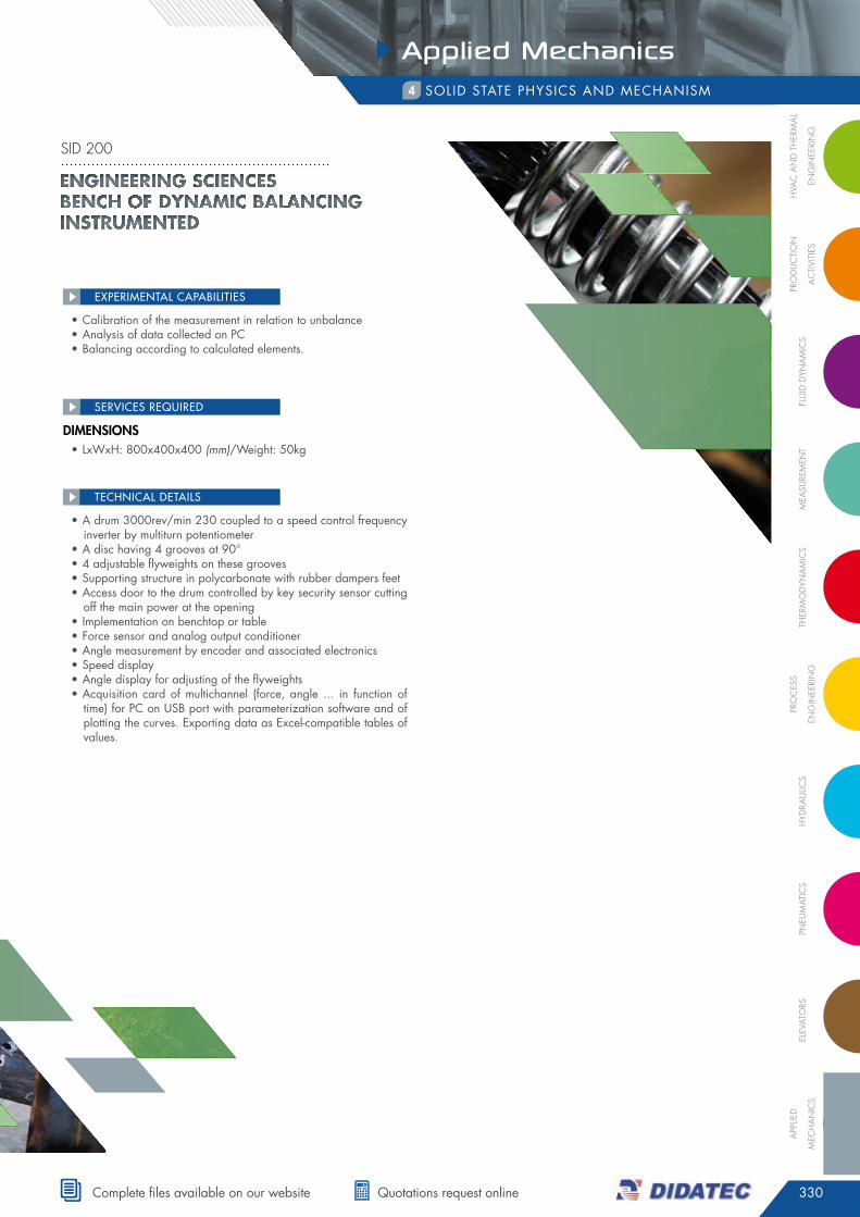
330
Applied Mechanics
FLU
ID D
YNA
MIC
SM
eASU
reM
eNt
tHer
MO
DYN
AM
ICS
PrO
CeS
S
eNG
INee
rIN
GH
YDrA
ULIC
SPN
eUM
AtIC
SeL
eVAt
OrS
APP
LIeD
MeC
HA
NIC
S
PrO
DU
CtI
ON
AC
tIVI
tIeS
HVA
C A
ND
tH
erM
AL
eNG
INee
rIN
G
complete files available on our website quotations request online
sOLid sTaTe phYsics and mechanism4
• calibration of the measurement in relation to unbalance• analysis of data collected on pc• Balancing according to calculated elements.
EXPERIMENTAL CAPABILITIES
• a drum 3000rev/min 230 coupled to a speed control frequency inverter by multiturn potentiometer
• a disc having 4 grooves at 90°• 4 adjustable flyweights on these grooves• supporting structure in polycarbonate with rubber dampers feet• access door to the drum controlled by key security sensor cutting
off the main power at the opening• implementation on benchtop or table• force sensor and analog output conditioner• angle measurement by encoder and associated electronics• speed display• angle display for adjusting of the flyweights• acquisition card of multichannel (force, angle ... in function of
time) for pc on usB port with parameterization software and of plotting the curves. exporting data as excel-compatible tables of values.
TEChNICAL dETAILS
sid 200
DiMensions• LxWxh: 800x400x400 (mm)/Weight: 50kg
SERVICES REQUIREd
EnginEEring sciEncEs BEnch of dynamic Balancing instrumEntEd

331
Applied Mechanics
tel. +33 (0)4 77 10 10 10 • www.didatec-technologie.com
sOLid sTaTe phYsics and mechanism4
general principle• This is a machine for characterizing the inertia of parts as well
as the dynamic effects of a heterogeneous distribution of material around an axis of rotation = measurement bench of the inertias
• for the study part of the distribution of the masses, this machine corresponds to a dynamic balancing bench
general structure• study bench consisting of a chassis anodized aluminum profiles
on damper feet with transparent casing• Three phase asynchronous motor 0.75kW mini - 1500rev/min
coupled with a transmission shaft mounted on ball bearings• hub at shaft end for attachment of the solids to characterize • encoder on shaft allowing to provide the speed informations as
well as the angular position of the shaft and the solid to charac-terize
• a gauge bridge force sensor for measuring the forces generated during a mass imbalance (unbalance)
• Torque sensor allowing the measurement on the shaft during ac-celeration/deceleration
• electrical box including: - main switch, circuit breakers and differential - push buttons on/off and potentiometer for speed adjustment - frequency control variator - speed display - Torque display - display of measured effort - display of the angular position of the system - analog module of data acquisition
• - 230V socket for connecting a pc on the box
specific Material to stuDy of tHe inertia• a set of disc diameters, thicknesses and materials sampled• a steel bar• a disc equipped with steel flyweights and adjustable position
(composition of the inertias / steiner’s theorem)• all these parts are equipped with fastening element to make them
integral with the transmission shaft and are housed in a sheet metal covert of safety
specific Material for stuDy of unBalance• graduated disk equipped with adjustable flyweights in steel
suMMary of eDucational applications• data acquisition and study of the following characteristics:
- Torque = f (rotational speed) - Torque = f (acceleration) - effort = f (rotational speed) - effort = f (angular position)
• study of the effects of inertia according to the geometry and den-sity of a solid in dynamic application
• study of the effects of the heterogeneous distribution of masses (unbalanced) in dynamic application
TEChNICAL dETAILS
supply• utility : 230V 50hz mono phase
DiMensions• LxWxh: 1000x800x1600 (mm)/Weight: 100kg approx
SERVICES REQUIREd
• study of the relation between the geometry of the solid and its dynamic rotational behavior
• study of the fundamental principle of dynamics• study of inertia• study of unbalances and the relation between mass, unbalance
position, rotation speed and unbalanced effort.• steiner’s theorem• demonstration of the resonance phenomenon
EXPERIMENTAL CAPABILITIES
EnginEEring sciEncEs Dynamic stuDy bEnch of thE massEs Distribution
sid 400
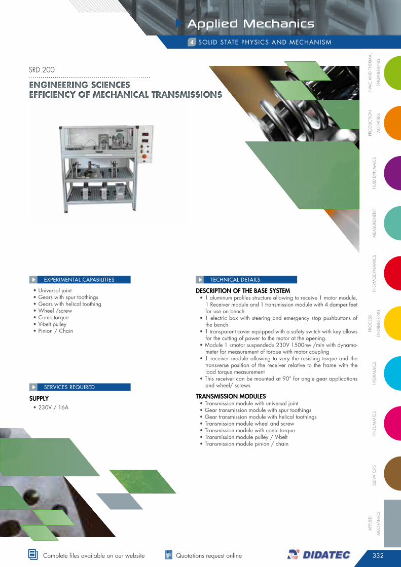
332
Applied Mechanics
FLU
ID D
YNA
MIC
SM
eASU
reM
eNt
tHer
MO
DYN
AM
ICS
PrO
CeS
S
eNG
INee
rIN
GH
YDrA
ULIC
SPN
eUM
AtIC
SeL
eVAt
OrS
APP
LIeD
MeC
HA
NIC
S
PrO
DU
CtI
ON
AC
tIVI
tIeS
HVA
C A
ND
tH
erM
AL
eNG
INee
rIN
G
complete files available on our website quotations request online
sOLid sTaTe phYsics and mechanism4
• universal joint• gears with spur toothings• gears with helical toothing• Wheel /screw• conic torque• V-belt pulley• pinion / chain
EXPERIMENTAL CAPABILITIES
Description of tHe Base systeM• 1 aluminum profiles structure allowing to receive 1 motor module,
1 receiver module and 1 transmission module with 4 damper feet for use on bench
• 1 electric box with steering and emergency stop pushbuttons of the bench
• 1 transparent cover equipped with a safety switch with key allows for the cutting of power to the motor at the opening.
• module 1 «motor suspended» 230V 1500rev /min with dynamo-meter for measurement of torque with motor coupling
• 1 receiver module allowing to vary the resisting torque and the transverse position of the receiver relative to the frame with the load torque measurement
• This receiver can be mounted at 90° for angle gear applications and wheel/ screws
transMission MoDules• Transmission module with universal joint• gear transmission module with spur toothings• gear transmission module with helical toothings• Transmission module wheel and screw• Transmission module with conic torque • Transmission module pulley / V-belt• Transmission module pinion / chain
TEChNICAL dETAILS
supply• 230V / 16a
SERVICES REQUIREd
EnginEEring sciEncEs EfficiEncy of mEchanical transmissions
srd 200
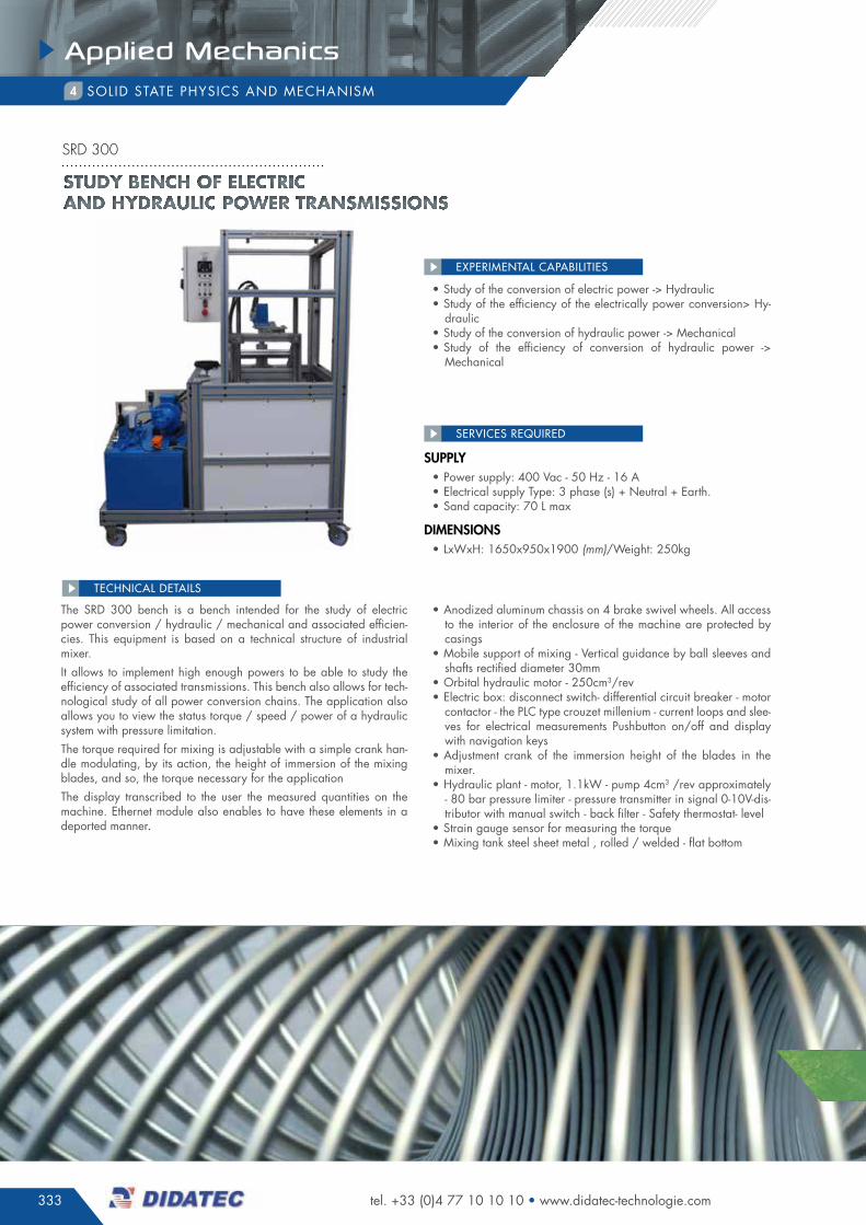
333
Applied Mechanics
tel. +33 (0)4 77 10 10 10 • www.didatec-technologie.com
sOLid sTaTe phYsics and mechanism4
• study of the conversion of electric power -> hydraulic• study of the efficiency of the electrically power conversion> hy-
draulic• study of the conversion of hydraulic power -> mechanical• study of the efficiency of conversion of hydraulic power ->
mechanical
EXPERIMENTAL CAPABILITIES
The srd 300 bench is a bench intended for the study of electric power conversion / hydraulic / mechanical and associated efficien-cies. This equipment is based on a technical structure of industrial mixer.it allows to implement high enough powers to be able to study the efficiency of associated transmissions. This bench also allows for tech-nological study of all power conversion chains. The application also allows you to view the status torque / speed / power of a hydraulic system with pressure limitation.The torque required for mixing is adjustable with a simple crank han-dle modulating, by its action, the height of immersion of the mixing blades, and so, the torque necessary for the applicationThe display transcribed to the user the measured quantities on the machine. ethernet module also enables to have these elements in a deported manner.
• anodized aluminum chassis on 4 brake swivel wheels. all access to the interior of the enclosure of the machine are protected by casings
• mobile support of mixing - Vertical guidance by ball sleeves and shafts rectified diameter 30mm
• Orbital hydraulic motor - 250cm3/rev• electric box: disconnect switch- differential circuit breaker - motor
contactor - the pLc type crouzet millenium - current loops and slee-ves for electrical measurements pushbutton on/off and display with navigation keys
• adjustment crank of the immersion height of the blades in the mixer.
• hydraulic plant - motor, 1.1kW - pump 4cm3 /rev approximately - 80 bar pressure limiter - pressure transmitter in signal 0-10V-dis-tributor with manual switch - back filter - safety thermostat- level
• strain gauge sensor for measuring the torque• mixing tank steel sheet metal , rolled / welded - flat bottom
TEChNICAL dETAILS
supply• power supply: 400 Vac - 50 hz - 16 a• electrical supply Type: 3 phase (s) + neutral + earth.• sand capacity: 70 L max
DiMensions• LxWxh: 1650x950x1900 (mm)/Weight: 250kg
SERVICES REQUIREd
STUDY BENCH OF ELECTRIC AND HYDRAULIC POWER TRANSMISSIONS
srd 300
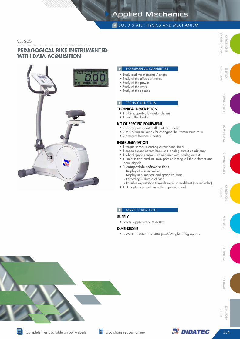
334
Applied Mechanics
FLU
ID D
YNA
MIC
SM
eASU
reM
eNt
tHer
MO
DYN
AM
ICS
PrO
CeS
S
eNG
INee
rIN
GH
YDrA
ULIC
SPN
eUM
AtIC
SeL
eVAt
OrS
APP
LIeD
MeC
HA
NIC
S
PrO
DU
CtI
ON
AC
tIVI
tIeS
HVA
C A
ND
tH
erM
AL
eNG
INee
rIN
G
complete files available on our website quotations request online
• study and the moments / efforts• study of the effects of inertia• study of the power • study of the work• study of the speeds
EXPERIMENTAL CAPABILITIES
tecHnical Description • 1 bike supported by metal chassis• 1 controlled brake
kit of specific equipMent• 2 sets of pedals with different lever arms• 2 sets of transmissions for changing the transmission ratio• 2 different flywheels inertia.
instruMentation• 1 torque sensor + analog output conditioner• 1 speed sensor bottom bracket + analog output conditioner• 1 wheel speed sensor + conditioner with analog output• 1 acquisition card on usB port collecting all the different ana-
logue signals• 1 compatible software for :
- display of current values - display in numerical and graphical form - recording + data archiving. - possible exportation towards excel spreadsheet (not included)
• 1 pc laptop compatible with acquisition card
TEChNICAL dETAILS
supply• power supply 230V 50-60hz
DiMensions• LxWxh: 1100x600x1400 (mm)/Weight: 70kg approx
SERVICES REQUIREd
Pedagogical bike instrumented with data acquisition
vel 200
sOLid sTaTe phYsics and mechanism4

NOTES