tebis application software - hager.ie · 1 6t 7829a tebis application software wdl620a v1.x tebis...
TRANSCRIPT
Tebis application software
WDL620A V1.x Tebis KNX push buttonsRoom controller and regulator and key sensors tebis
Electrical/Mechanical characteristics: see user's instructions
Product reference Product designation
WYT62x Room controller and regulator and multifunction key sensors
WUT06 V2 BAU for WYT61x and WYT62x
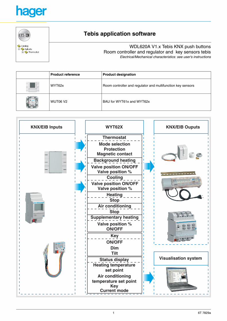
KNX/EIB Inputs KNX/EIB OuputsWYT62X
Mode selection
Thermostat
Cooling
ProtectionMagnetic contact
Background heating
Valve position ON/OFFValve position %
Valve position ON/OFF
ON/OFF
ON/OFFDimTilt
Status display
Key
Heating temperatureset point
Air conditioningtemperature set point
Current modeKey
Valve position %
Valve position %
HeatingStop
Air conditioningStop
Supplementary heating
Visualisation system
1 6T 7829a
1. Presentation of the functions ........................................................................................................................................ 4
1.1 Presentation of the room controller and regulator functions................................................................................... 41.1.1 Thermostat with 4 push buttons ............................................................................................................................ 61.1.2 Thermostat with 6 push buttons ............................................................................................................................ 61.1.3 Thermostat for fan coil .......................................................................................................................................... 7
1.2 Presentation of the push buttons functions .............................................................................................................. 7
2. General configuration and parameterising of the thermostat functional modes ..................................................... 8
3. Configuration and parameterising of the push buttons............................................................................................ 103.1 List of objects operated by independent push buttons .............................................................................................. 10
3.1.1 List of objects operated by linked push buttons .................................................................................................. 113.2 General parameters................................................................................................................................................... 12
3.2.1 Label holder backlight and indicator colours ....................................................................................................... 123.2.2 Key jamming and Antitheft alarm ........................................................................................................................ 133.2.3 Indicator ON period and length of (long/short) key-presses................................................................................ 13
3.3 "Buttons use" parameters.......................................................................................................................................... 143.4 Level selection parameters........................................................................................................................................ 153.5 Linked or independent push button parameters ........................................................................................................ 17
3.5.1 Indicator parameters ........................................................................................................................................... 173.5.2 Jamming function parameters............................................................................................................................. 183.5.3 Parameters for linked or independent push buttons ........................................................................................... 18
3.5.3.1 Description of the ON/OFF, toggle switch, time-limited toggle switch and timer functions ............................ 183.5.3.2 ON/OFF function parameters for independent push buttons......................................................................... 193.5.3.3 Toggle switch function parameters for independent push buttons ................................................................ 203.5.3.4 ON/OFF function parameters for linked push buttons ................................................................................... 203.5.3.5 Dimming function ........................................................................................................................................... 21
3.5.3.5.1 Dimming function parameters for independent push buttons.................................................................. 213.5.3.5.2 Dimming function parameters for linked push buttons ............................................................................ 22
3.5.3.6 Up/Down function .......................................................................................................................................... 233.5.3.6.1 Up/Down function parameters for independent push buttons ................................................................. 233.5.3.6.2 Up/Down function parameters for linked push buttons............................................................................ 24
3.5.3.7 Heating setpoint selection function ................................................................................................................ 243.5.3.7.1 Heating setpoint function parameters for independent push buttons ...................................................... 253.5.3.7.2 Heating setpoint function parameters for linked push buttons ................................................................ 26
3.5.3.8 Priority function .............................................................................................................................................. 273.5.3.8.1 Priority function parameters for independent push buttons..................................................................... 273.5.3.8.2 Priority function parameters for linked push buttons ............................................................................... 28
3.5.3.9 Scene function ............................................................................................................................................... 293.5.3.9.1 Scene function parameters for independent push buttons...................................................................... 29
3.5.3.10 Value function .............................................................................................................................................. 303.5.3.10.1 Value function parameters for independent push buttons..................................................................... 303.5.3.10.2 2-channel ON/OFF function .................................................................................................................. 313.5.3.10.3 2-channel ON/OFF mode function parameters for independent push buttons...................................... 313.5.3.10.4 2-channel ON/OFF mode function parameters for linked push buttons ................................................ 32
3.5.3.11 2-channel mode value function.................................................................................................................... 323.5.3.11.1 2-channel value mode function parameters for independent push buttons........................................... 32
4. Configuration and parameterising of the room controller and regulator................................................................ 344.1 List of objects Room controller and regulator ............................................................................................................ 344.2 Thermostat settings parameter window..................................................................................................................... 38
4.2.1 Installation type setting........................................................................................................................................ 384.2.2 Use of the control push buttons of the regulator ().............................................................................................. 404.2.3 Time-limited Comfort mode - controlled via the bus............................................................................................ 414.2.4 Mode when power ON ........................................................................................................................................ 414.2.5 Cyclic emission of the Current mode and Heating/Air-conditioning status indications........................................ 424.2.6 Jamming the buttons........................................................................................................................................... 434.2.7 Valve protection .................................................................................................................................................. 43
4.3 Heating installation parameters ................................................................................................................................. 444.3.1 Installation characteristics ................................................................................................................................... 44
4.3.1.1 Selection of the Room transmitter type and activation of the supplementary heating ................................... 464.3.1.2 External temperature and floor temperature limit........................................................................................... 47
4.3.2 Emission conditions ............................................................................................................................................ 494.3.3 Fan speed control ............................................................................................................................................... 50
4.4 Background heating instructions parameter .............................................................................................................. 514.5 Parameterising of the Supplementary heating .......................................................................................................... 524.6 Customized Heating setting parameters ................................................................................................................... 534.7 Air-conditioning installation parameters..................................................................................................................... 54
4.7.1 Installation characteristics ................................................................................................................................... 544.7.1.1 Floor temperature limit function........................................................................................................................ 55
4.8 Air-conditioning instructions parameters ................................................................................................................... 564.8.1 Parameters setting for the Air-conditioning type Heating and Air-conditioning ................................................... 57
Summary
WYT62x - ETS 2 6T 7829a
4.9 Customized Air-conditioning setting parameters ....................................................................................................... 584.10 Parameter value Measurement characteristics ....................................................................................................... 594.11 Scene parameters ................................................................................................................................................... 60
5. Characteristics .............................................................................................................................................................. 61
6. Physical addressing and presence of the bus........................................................................................................... 61
WYT62x - ETS 3 6T 7829a
The WYT62x device is a multifunction room controller and regulator with LCD display. It works according to 3 modes:thermostat and 4 generic push buttons, thermostat and 6 generic push buttons and thermostat for fan coil.The display shows the following information:
- Current ambient temperature,- Current mode (Comfort, Standby, Reduced, Protection),- Current temperature setpoint,- Speed of ventilation.
The functions may be assigned to the 6 push buttons according to use (lighting, shutter, scene settings).The WYT62x can be used with the Bus Access Unit WUT06 V2.
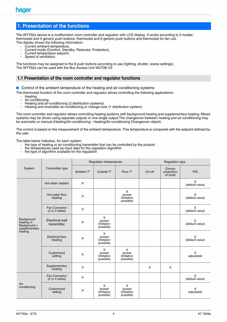
■ Control of the ambient temperature of the heating and air-conditioning systemsThe thermostat function of the room controller and regulator allows controlling the following applications:
- Heating.- Air-conditioning.- Heating and air-conditioning (2 distribution systems).- Heating and reversible air-conditioning or change-over (1 distribution system).
The room controller and regulator allows controlling heating systems with background heating and supplementary heating. Mixed systems may be driven using separate outputs or one single output.The changeover between heating and air-conditioning may be automatic or manual (Heating/Air-conditioning - Heating/Air-conditioning Changeover object).
The control is based on the measurement of the ambient temperature. This temperature is compared with the setpoint defined by the user.
The table below indicates, for each system:- the type of heating or air-conditioning transmitter that can be controlled by the product- the temperatures used as input data for the regulation algorithm- the type of algorithm available for the regulation
1. Presentation of the functions
1.1 Presentation of the room controller and regulator functions
System Transmitter type
Regulation temperatures Regulation type
Ambient T° Outside T° Floor T° On-offChrono
proportional cycle
PID
Background heating orBackground + supplementary heating
Hot water radiator X X(default value)
Hot water floor heating X
X(power
limitation possible)
X(default value)
Fan Convector (2 or 4 tubes) X X
(default value)
Electrical wall transmitter X
X(power
limitation possible)
X(default value)
Electrical floor heating X
X(power
limitation possible)
X(default value)
Customized setting X
X(power
limitation possible)
X(power
limitation possible)
Xadjustable
Supplementary heating X X X
Air-conditioning
Fan Convector (2 or 4 tubes) X X
(default value)
Customized setting X
X(power
limitation possible)
X(power
limitation possible)
Xadjustable
WYT62x - ETS 4 6T 7829a

■ Operating modesThe room controller and regulator can operate in the following modes:
- Comfort- Reduced- Economy- Protection
Mode selection may occur by means of a push button, priority, derogation, a timer, a clock or by activating a scene.A temperature setpoint is associated with each mode.
■ Protection The Protection function allows protecting a building (installation) against the risks linked with frost in winter and with a too high temperature in summer. The Frost protection function is active in Heating mode and the Equipment protection function is active in Air-conditioning mode.
■ Timed ComfortThe regulator may be switched over to Comfort mode for a duration that can be defined in the parameters.It returns automatically to the last mode set when this time has elapsed.
■ PriorityThe Priority allows switching the regulator to Protection mode as well as to Comfort mode.
■ Fan speedThe Fan speed function allows setting the ventilation speed of a fan convector. The speed may be fixed according to 3 levels: speed 1 to 3 increasing.
■ Power limitationThe call for energy (heating rate %) can be limited. Limitation is possible for the following installations:
- Electrical heating.- Heating floor (electrical or water).- Customized installation (Customized setting).
The heating/cooling power called for by the room controller and regulator may be limited:- according to the outside temperature.
The temperatures are measured using separate sensors and sent to the regulator by means of the objects Temperature External temperature and Temperature Floor temperature.
■ Valve protection functionThe room controller and regulator can open the controlled valves and circulation pumps periodically to prevent them from jamming.
■ JammingThe functions of the control push buttons ( ) may be blocked (jammed) via the bus. The parameters allow defining which buttons are to be jammed and whith which value (0 or 1) they are to be jammed.
■ SceneThe room controller and regulator can be integrated in up to 32 scenes. Calling the scenes allows switching the room controller and regulator to the following modes:
- Comfort- Economy- Reduced- Frost protection
Storing the mode (Comfort, Standby, etc.) for the scenes (1 to 8) via the bus may be authorized or forbidden via the parameters.
■ Status displayThe following values may be displayed via the bus:
- Current mode (Comfort,...).- Room temperature.- System selection (heating, air-conditioning)- Heating temperature setpoint- Air-conditioning temperature setpoint
■ Magnetic contactA magnetic contact may be integrated in the system for the selection of the Frost protection or Equipment protection mode. The regulator is controlled by the Thermostat - Magnetic contact object.
+- M
WYT62x - ETS 5 6T 7829a
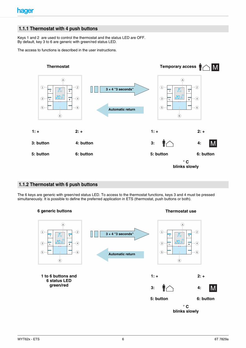
Keys 1 and 2 are used to control the thermostat and the status LED are OFF.By default, key 3 to 6 are generic with green/red status LED.
The access to functions is described in the user instructions.
The 6 keys are generic with green/red status LED. To access to the thermostat functions, keys 3 and 4 must be pressed simultaneously. It is possible to define the preferred application in ETS (thermostat, push buttons or both).
1.1.1 Thermostat with 4 push buttons
1.1.2 Thermostat with 6 push buttons
2
E
4
6
1
3
5
A
Thermostat Temporary access
3: button
5: button 6: button
4: button
5: button 6: button
1: + 1: +2: + 2: +
2
E
4
6
1
3
5
A
Automatic return
3 + 4 "3 seconds"
4: 3:
° C blinks slowly
1 to 6 buttons and 6 status LED
green/red
2
E
4
6
1
3
5
A
6 generic buttons Thermostat use
5: button
1: + 2: +
2
E
4
6
1
3
5
A
Automatic return
3 + 4 "3 seconds"
4: 3:
° C blinks slowly
6: button
WYT62x - ETS 6 6T 7829a
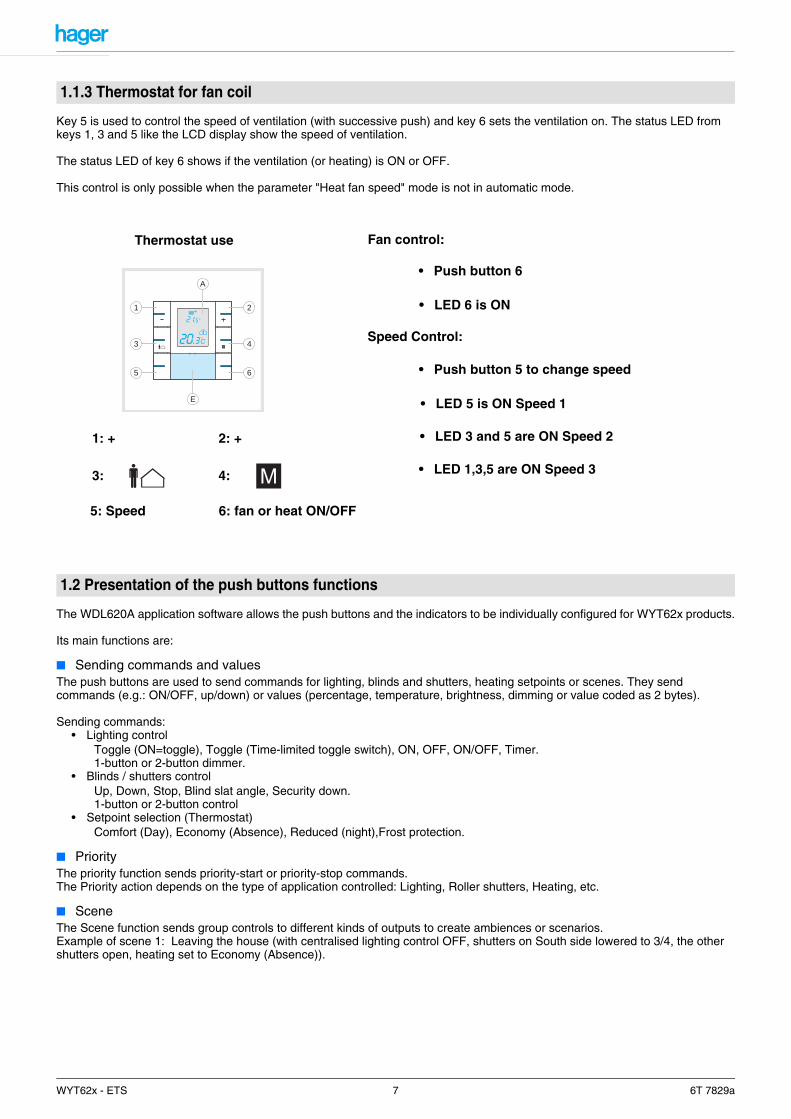
Key 5 is used to control the speed of ventilation (with successive push) and key 6 sets the ventilation on. The status LED from keys 1, 3 and 5 like the LCD display show the speed of ventilation.
The status LED of key 6 shows if the ventilation (or heating) is ON or OFF.
This control is only possible when the parameter "Heat fan speed" mode is not in automatic mode.
The WDL620A application software allows the push buttons and the indicators to be individually configured for WYT62x products.
Its main functions are:
■ Sending commands and valuesThe push buttons are used to send commands for lighting, blinds and shutters, heating setpoints or scenes. They send commands (e.g.: ON/OFF, up/down) or values (percentage, temperature, brightness, dimming or value coded as 2 bytes).
Sending commands:• Lighting control
Toggle (ON=toggle), Toggle (Time-limited toggle switch), ON, OFF, ON/OFF, Timer.1-button or 2-button dimmer.
• Blinds / shutters controlUp, Down, Stop, Blind slat angle, Security down.1-button or 2-button control
• Setpoint selection (Thermostat)Comfort (Day), Economy (Absence), Reduced (night),Frost protection.
■ PriorityThe priority function sends priority-start or priority-stop commands.The Priority action depends on the type of application controlled: Lighting, Roller shutters, Heating, etc.
■ SceneThe Scene function sends group controls to different kinds of outputs to create ambiences or scenarios.Example of scene 1: Leaving the house (with centralised lighting control OFF, shutters on South side lowered to 3/4, the other shutters open, heating set to Economy (Absence)).
1.1.3 Thermostat for fan coil
1.2 Presentation of the push buttons functions
2
E
4
6
1
3
5
A
Thermostat use Fan control:
5: Speed 6: fan or heat ON/OFF
1: + 2: +
4: 3:
• Push button 6
• LED 6 is ON
Speed Control:
• LED 5 is ON Speed 1
• Push button 5 to change speed
• LED 3 and 5 are ON Speed 2
• LED 1,3,5 are ON Speed 3
WYT62x - ETS 7 6T 7829a
■ Status indication by indicatorEach push button is equipped with an indicator to confirm pressing or to indicate the statuses of the controlled outputs. The indicator (brightness, colour, flashing) and its operation mode (always ON, always OFF, status indication or status confirmation) are settable.
■ Using the keysKey operation can be defined.
• Linked push buttons: Key operation is linked (e.g. left key = shutter lowering and right key = shutter raising)• Independent push buttons: Key operation is linked (e.g. left key = shutter raising/lowering/stop and right key = light
dimming).
■ JammingThe Jamming function locks the push button via a bus object. No commands or values can be sent to the bus.
■ 2-channel modeThe 2-channel mode is used to perform two different functions using the same push button. The distinction between the two functions is between a short key-press and a long key-press(the duration of the long key-press is settable).
■ Level selectionThe second level (activated by the Level selection object) can be used to either deactivate the key's function or to change it. An additional function cannot be defined. Infrared channels or linked push buttons are not concerned by this level selection function.
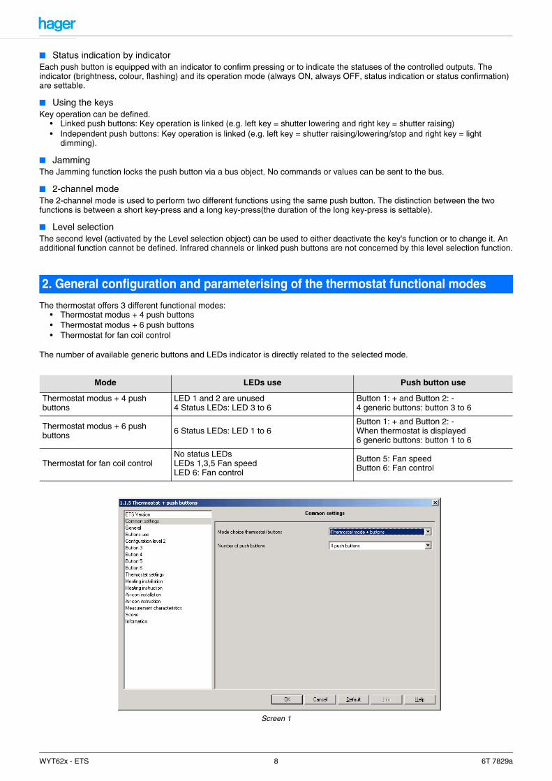
The thermostat offers 3 different functional modes:• Thermostat modus + 4 push buttons• Thermostat modus + 6 push buttons• Thermostat for fan coil control
The number of available generic buttons and LEDs indicator is directly related to the selected mode.
Screen 1
2. General configuration and parameterising of the thermostat functional modes
Mode LEDs use Push button use
Thermostat modus + 4 push buttons
LED 1 and 2 are unused4 Status LEDs: LED 3 to 6
Button 1: + and Button 2: -4 generic buttons: button 3 to 6
Thermostat modus + 6 push buttons 6 Status LEDs: LED 1 to 6
Button 1: + and Button 2: -When thermostat is displayed6 generic buttons: button 1 to 6
Thermostat for fan coil controlNo status LEDsLEDs 1,3,5 Fan speedLED 6: Fan control
Button 5: Fan speedButton 6: Fan control
WYT62x - ETS 8 6T 7829a
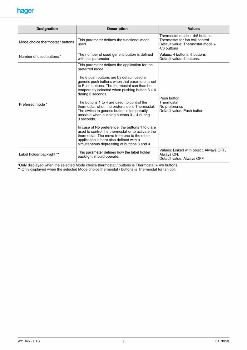
*Only displayed when the selected Mode choice thermostat / buttons is Thermostat + 4/6 buttons.** Only displayed when the selected Mode choice thermostat / buttons is Thermostat for fan coil.
Designation Description Values
Mode choice thermostat / buttons This parameter defines the functional mode used.
Thermostat mode + 4/6 buttonsThermostat for fan coil controlDefault value: Thermostat mode + 4/6 buttons
Number of used buttons * The number of used generic button is defined with this parameter.
Values: 4 buttons, 6 buttonsDefault value: 4 buttons.
Preferred mode *
This parameter defines the application for the preferred mode.
The 6 push buttons are by default used a generic push buttons when that parameter is set to Push buttons. The thermostat can than be temporarily selected when pushing button 3 + 4 during 3 seconds.
The buttons 1 to 4 are used to control the thermostat when the preference is Thermostat.The switch to generic button is temporarily possible when pushing buttons 3 + 4 during 3 seconds.
In case of No preference, the buttons 1 to 6 are used to control the thermostat or to activate the thermostat. The move from one to the other application is here also defined with a simultaneous depressing of buttons 3 and 4.
Push buttonThermostatNo preferenceDefault value: Push button
Label holder backlight ** This parameter defines how the label holder backlight should operate.
Values: Linked with object, Always OFF, Always ON.Default value: Always OFF
WYT62x - ETS 9 6T 7829a
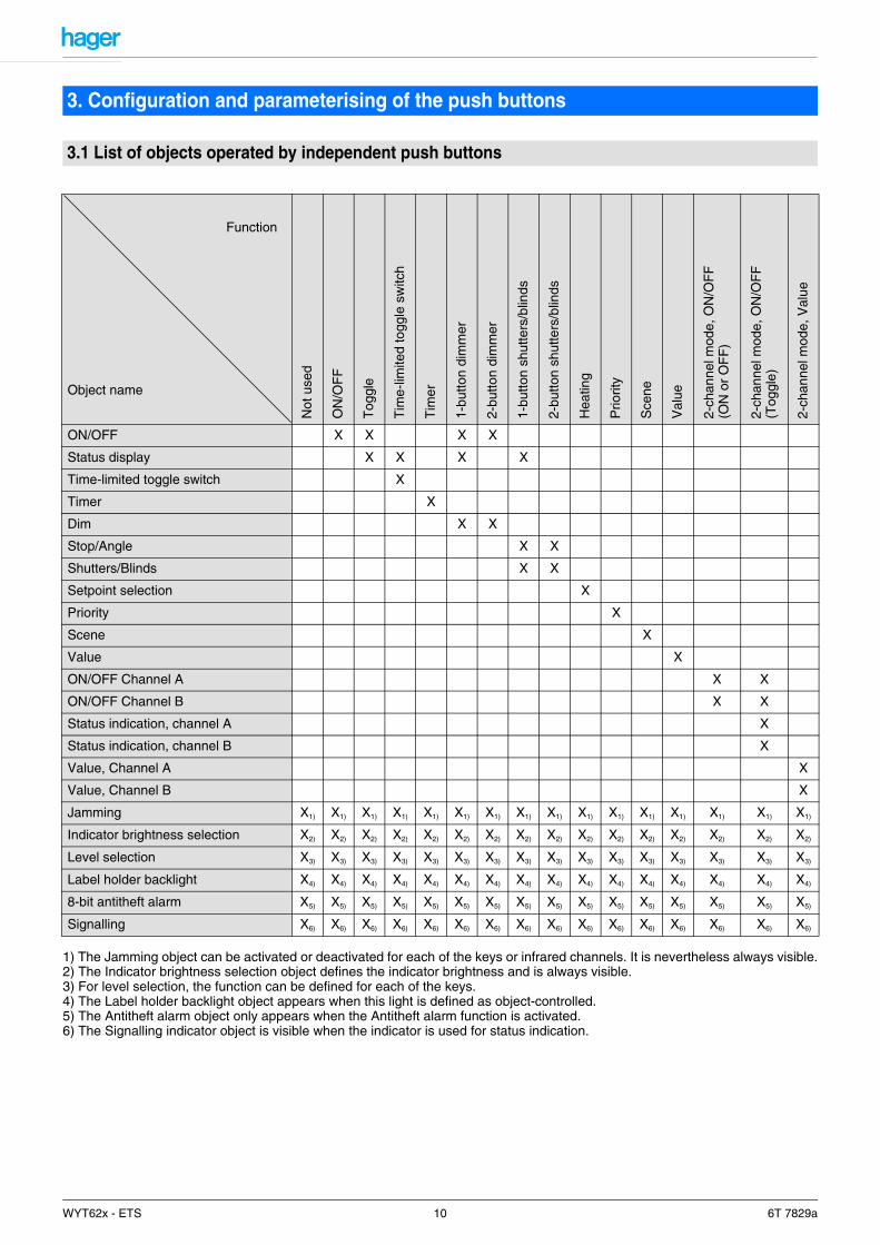
1) The Jamming object can be activated or deactivated for each of the keys or infrared channels. It is nevertheless always visible.2) The Indicator brightness selection object defines the indicator brightness and is always visible.3) For level selection, the function can be defined for each of the keys.4) The Label holder backlight object appears when this light is defined as object-controlled.5) The Antitheft alarm object only appears when the Antitheft alarm function is activated.6) The Signalling indicator object is visible when the indicator is used for status indication.
3. Configuration and parameterising of the push buttons
3.1 List of objects operated by independent push buttons
Function
Object name
Not
use
d
ON
/OF
F
Tog
gle
Tim
e-lim
ited
togg
le s
witc
h
Tim
er
1-bu
tton
dim
mer
2-bu
tton
dim
mer
1-bu
tton
shut
ters
/blin
ds
2-bu
tton
shut
ters
/blin
ds
Hea
ting
Prio
rity
Sce
ne
Val
ue
2-ch
anne
l mod
e, O
N/O
FF
(ON
or
OF
F)
2-ch
anne
l mod
e, O
N/O
FF
(Tog
gle)
2-ch
anne
l mod
e, V
alue
ON/OFF X X X X
Status display X X X X
Time-limited toggle switch X
Timer X
Dim X X
Stop/Angle X X
Shutters/Blinds X X
Setpoint selection X
Priority X
Scene X
Value X
ON/OFF Channel A X X
ON/OFF Channel B X X
Status indication, channel A X
Status indication, channel B X
Value, Channel A X
Value, Channel B X
Jamming X1) X1) X1) X1) X1) X1) X1) X1) X1) X1) X1) X1) X1) X1) X1) X1)
Indicator brightness selection X2) X2) X2) X2) X2) X2) X2) X2) X2) X2) X2) X2) X2) X2) X2) X2)
Level selection X3) X3) X3) X3) X3) X3) X3) X3) X3) X3) X3) X3) X3) X3) X3) X3)
Label holder backlight X4) X4) X4) X4) X4) X4) X4) X4) X4) X4) X4) X4) X4) X4) X4) X4)
8-bit antitheft alarm X5) X5) X5) X5) X5) X5) X5) X5) X5) X5) X5) X5) X5) X5) X5) X5)
Signalling X6) X6) X6) X6) X6) X6) X6) X6) X6) X6) X6) X6) X6) X6) X6) X6)
WYT62x - ETS 10 6T 7829a
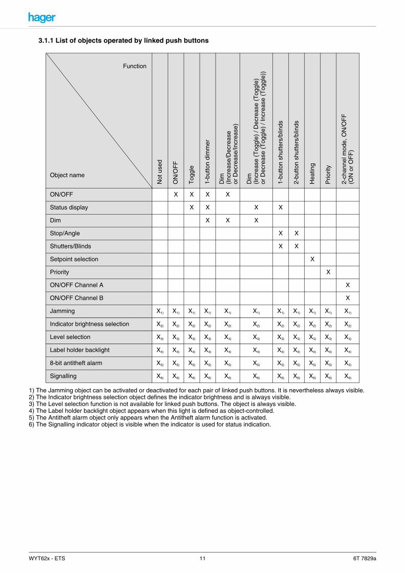
3.1.1 List of objects operated by linked push buttons
1) The Jamming object can be activated or deactivated for each pair of linked push buttons. It is nevertheless always visible.2) The Indicator brightness selection object defines the indicator brightness and is always visible.3) The Level selection function is not available for linked push buttons. The object is always visible.4) The Label holder backlight object appears when this light is defined as object-controlled.5) The Antitheft alarm object only appears when the Antitheft alarm function is activated.6) The Signalling indicator object is visible when the indicator is used for status indication.
Function
Object name
Not
use
d
ON
/OF
F
Tog
gle
1-bu
tton
dim
mer
Dim
(Inc
reas
e/D
ecre
ase
or D
ecre
ase/
Incr
ease
)
Dim
(Inc
reas
e (T
oggl
e) /
Dec
reas
e (T
oggl
e)or
Dec
reas
e (T
oggl
e) /
Incr
ease
(T
oggl
e))
1-bu
tton
shut
ters
/blin
ds
2-bu
tton
shut
ters
/blin
ds
Hea
ting
Prio
rity
2-ch
anne
l mod
e, O
N/O
FF
(ON
or
OF
F)
ON/OFF X X X X
Status display X X X X
Dim X X X
Stop/Angle X X
Shutters/Blinds X X
Setpoint selection X
Priority X
ON/OFF Channel A X
ON/OFF Channel B X
Jamming X1) X1) X1) X1) X1) X1) X1) X1) X1) X1) X1)
Indicator brightness selection X2) X2) X2) X2) X2) X2) X2) X2) X2) X2) X2)
Level selection X3) X3) X3) X3) X3) X3) X3) X3) X3) X3) X3)
Label holder backlight X4) X4) X4) X4) X4) X4) X4) X4) X4) X4) X4)
8-bit antitheft alarm X5) X5) X5) X5) X5) X5) X5) X5) X5) X5) X5)
Signalling X6) X6) X6) X6) X6) X6) X6) X6) X6) X6) X6)
WYT62x - ETS 11 6T 7829a
3.2.1 Label holder backlight and indicator colours
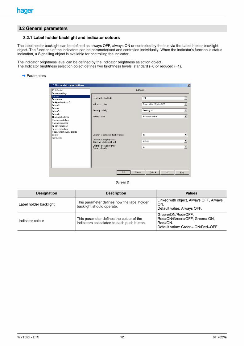
The label holder backlight can be defined as always OFF, always ON or controlled by the bus via the Label holder backlight object. The functions of the indicators can be parameterised and controlled individually. When the indicator's function is status indication, a Signalling object is available for controlling the indicator.
The indicator brightness level can be defined by the Indicator brightness selection object.The Indicator brightness selection object defines two brightness levels: standard (=0)or reduced (=1).
➜ Parameters
Screen 2
3.2 General parameters
Designation Description Values
Label holder backlight This parameter defines how the label holder backlight should operate.
Linked with object, Always OFF, Always ON.Default value: Always OFF.
Indicator colour This parameter defines the colour of the indicators associated to each push button.
Green=ON/Red=OFF, Red=ON/Green=OFF, Green= ON, Red=ON.Default value: Green= ON/Red=OFF.
WYT62x - ETS 12 6T 7829a
3.2.2 Key jamming and Antitheft alarm
Key locking can be individually defined for each key. Key locking is activated by the Jamming object.When the theft protection function is used, the BCU detects that the push button mechanism has been removed and emits an alarm signal via the Antitheft Alarm object.The information is transmitted via the 1-bit antitheft alarm object or the 8-bit antitheft alarm object.
➜ Parameter Setting screen: See "Screen 2".
* These parameters are only visible if the Antitheft Alarm parameter has the value: 1-bit alarm or 8-bit alarm.** This parameter is only visible if the "Antitheft alarm upon dismantling" parameter has the value: 1-byte alarm.
3.2.3 Indicator ON period and length of (long/short) key-presses
➜ Parameter Setting screen: See "Screen 2".
Designation Description Values
Jamming polarity
The Jamming function authorizes product locking. Jamming forbids sending commands. This parameter defines the level at which jamming is active.
Jamming set to 1, Jamming set to 0.Default value: Jamming set to 1.
Antitheft Alarm
This parameter defines the type of object sent upon push button removal.In the case of removal:
- In 1-bit configuration, a "1" will be sent regularly. If the mechanism is removed, a "0" will be sent regularly.
- In 1-byte configuration, the defined value will be sent regularly. If the mechanism is removed, value sending is stopped.
Not used, 1-bit alarm, 8-bit alarm.Default value: Not used.
Alarm emission period* This parameter defines the emission periodicity of the Antitheft alarm object.
1 min, 5 min, 10 min, 30 min.Default value: 10 min.
Alarm value** This parameter defines the value sent if the 8-bit alarm is active.
0 up to 255 in 1 steps.Default value: 0.
Designation Description Values
Duration to acknowledge key press
This parameter defines the indicator ON period for confirming push button presses.
0.5 s, 1 s, 2 s, 3 s.Default value: 3 s.
Duration of long key-press(Dim and Shutters/Blinds)
This parameter defines the duration of a long push button press for sending Dimming or Up/Down commands. In Timer mode, the length of this long key-press will be used to take account of a timer interruption.
400 ms, 500 ms, 600 ms, 700 ms, 800 ms, 900 ms, 1 s.Default value: 500 ms.
Duration of long key-press 2-channel mode
This parameter defines the length of a long push button press for activating 2-channel mode.
500 ms, 1 s, 2 s, 3 s, 4 s, 5 s, 6 s, 7 s, 8 s, 9 s, 10 s.Default value: 5 s.
WYT62x - ETS 13 6T 7829a
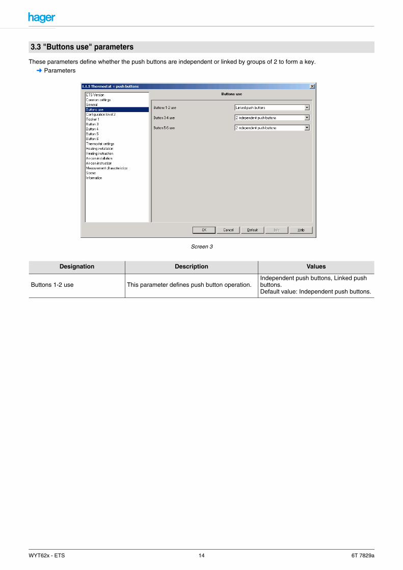
These parameters define whether the push buttons are independent or linked by groups of 2 to form a key.➜ Parameters
Screen 3
3.3 "Buttons use" parameters
Designation Description Values
Buttons 1-2 use This parameter defines push button operation.Independent push buttons, Linked push buttons.Default value: Independent push buttons.
WYT62x - ETS 14 6T 7829a

The second level (activated by the Level selection object) can be used to either deactivate the key's function or to change it. An additional function cannot be defined..
For example:Room with separation wall: Push buttons configured as ON/OFF
Situation: Separation wall open
Situation: Separation wall closed (The "divided wall open/closed" information can come from, for example, a control switch)
3.4 Level selection parameters
L1 L2 L1 L2
L1 L2 L1 L2
WYT62x - ETS 15 6T 7829a
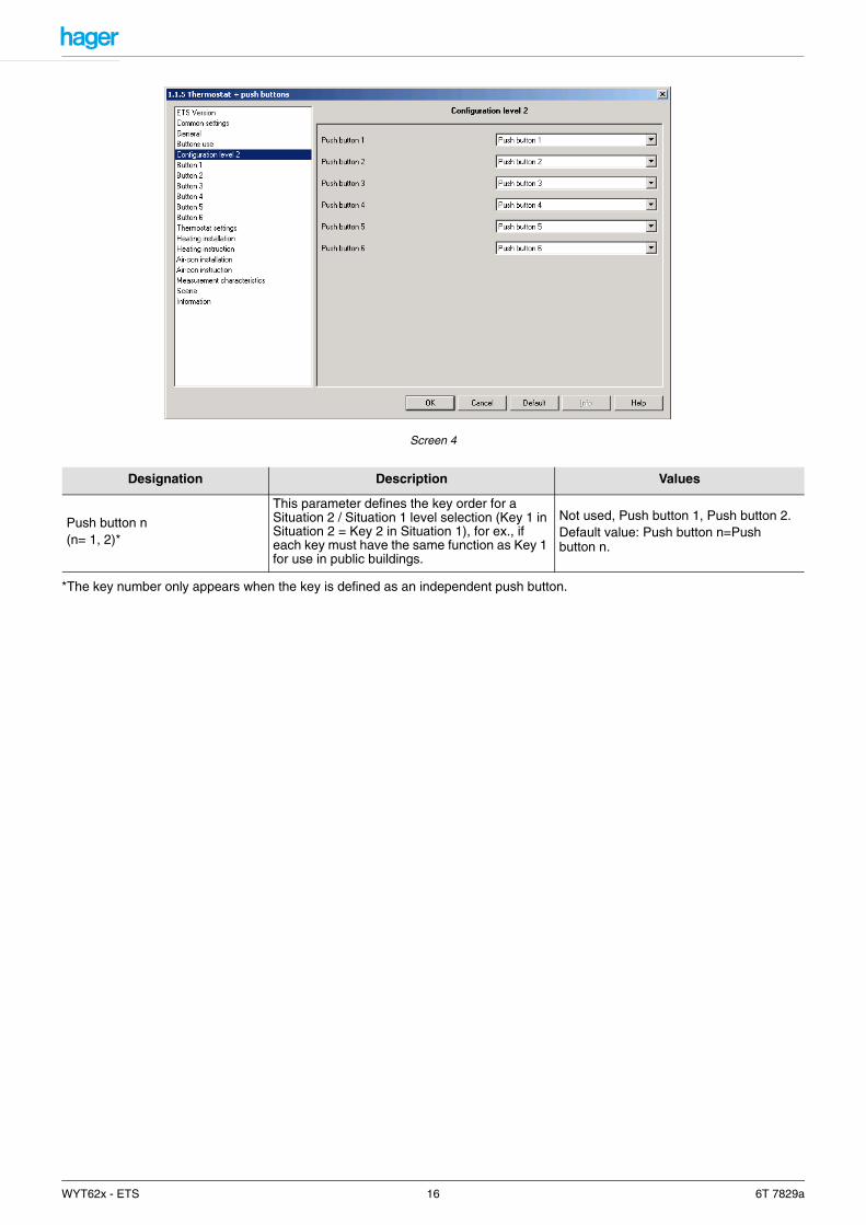
Screen 4
*The key number only appears when the key is defined as an independent push button.
Designation Description Values
Push button n(n= 1, 2)*
This parameter defines the key order for a Situation 2 / Situation 1 level selection (Key 1 in Situation 2 = Key 2 in Situation 1), for ex., if each key must have the same function as Key 1 for use in public buildings.
Not used, Push button 1, Push button 2.Default value: Push button n=Push button n.
WYT62x - ETS 16 6T 7829a
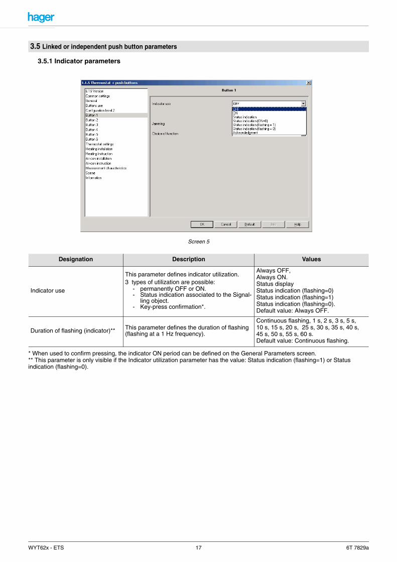
3.5.1 Indicator parameters
Screen 5
* When used to confirm pressing, the indicator ON period can be defined on the General Parameters screen.** This parameter is only visible if the Indicator utilization parameter has the value: Status indication (flashing=1) or Status indication (flashing=0).
3.5 Linked or independent push button parameters
Designation Description Values
Indicator use
This parameter defines indicator utilization.3 types of utilization are possible:
- permanently OFF or ON.- Status indication associated to the Signal-
ling object.- Key-press confirmation*.
Always OFF,Always ON.Status displayStatus indication (flashing=0)Status indication (flashing=1)Status indication (flashing=0).Default value: Always OFF.
Duration of flashing (indicator)** This parameter defines the duration of flashing (flashing at a 1 Hz frequency).
Continuous flashing, 1 s, 2 s, 3 s, 5 s, 10 s, 15 s, 20 s, 25 s, 30 s, 35 s, 40 s, 45 s, 50 s, 55 s, 60 s.Default value: Continuous flashing.
WYT62x - ETS 17 6T 7829a
3.5.2 Jamming function parameters
The Jamming function authorizes push button locking. Jamming forbids sending commands. This function is started by the General - Jamming object. Jamming is indicated by the indicator flashing for 5 seconds when the push button is pressed.
3.5.3 Parameters for linked or independent push buttons
Key 1 to Key 2 or Linked keys 1 parameters will be available depending on the type of operation defined for the keys (linked or independent). These parameters define the functions of the keys or linked keys. The functionalities available for independent or linked keys are not exactly identical.
3.5.3.1 Description of the ON/OFF, toggle switch, time-limited toggle switch and timer functions
ON/OFF:Pressing the independent push button or the linked push button switches the circuit ON or OFF (no change after pressing again).
Description: After pressing the independent push button or a side of the linked push button, an ON or OFF command will be sent to the bus via the ON/OFF object. The command sent is not linked to the output's previous status. The command to be sent (ON or OFF) must be defined in the parameters.
Furthermore, in independent push button operation, it can be specified whether the command must be sent when the push button is pressed or released (see parameter settings).
Toggle switch:In independent push button operation, the toggle switch function consists in inverting the output status. Each new key-press modifies the output status.
In linked push button operation, the toggle switch function consists in inverting the output status when a side of the button has been pressed. Each new key-press modifies the output status.
Description: When the independent push button or a side of the linked push button is pressed, depending on the Status indicationobject, an ON or OFF command will be sent to the bus via the ON/OFF object. The command sent to the bus is the inverse of theprevious command (previous command: ON -> OFF command sent; previous command: OFF -> ON command sent).
Time-limited toggle switch:This function is only available for an independent push button.
A short push button press: The output's status is inverted. The status changes after each new short key-press. If there is no short key-press, the output will be switched OFF once the delay time has elapsed. A long push button press restarts the delay time.
Description: A short key-press sends the Time-limited toggle switch object to the bus with the value of the inverse of the Status indication object. A long push button press sends an ON command via the Time-limited toggle switch object.
Upon reception of an ON command from the time-limited toggle switch, TXA-type products switch the output to ON for the set time. Upon reception of an OFF command from the time-limited toggle switch, the outputs switch to OFF. Reception of an ON command while the output is still set to ON restarts the delay time.
Timer:This function is only available for an independent push button.
A short push button press: The output contact switches to ON for the output's set time.A long push button press: Timer interruption and output stopped.
Description: A short key-press sends an ON command to the bus via the Timer object. A long key-press sends an OFF command to the bus via the Timer object.
Upon reception of an ON command from the Timer object, TXA-type products switch the output to ON for the time defined..An ON command on the Timer object repeated within 10 sec. increases the output's delay time period (for TXA-type products) as follows:
The delay time starts after the last key-press. An ON command received after the 10s resets the set delay time. An OFF command switches immediately the output to OFF.
Designation Description Values
Jamming This parameter defines whether push button jamming by a distinct object is permitted.
Not authorized, Authorized.Default value: Not authorized.
ON-switching time = (1 + Number of repeated key-presses) * time set.
WYT62x - ETS 18 6T 7829a
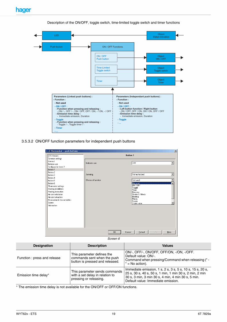
Description of the ON/OFF, toggle switch, time-limited toggle switch and timer functions
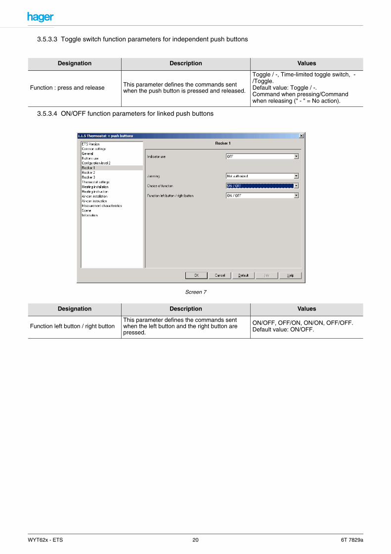
3.5.3.2 ON/OFF function parameters for independent push buttons
Screen 6
* The emission time delay is not available for the ON/OFF or OFF/ON functions.
Designation Description Values
Function : press and releaseThis parameter defines the commands sent when the push button is pressed and released.
ON/-, OFF/-, ON/OFF, OFF/ON, -/ON, -/OFF.Default value: ON/-.Command when pressing/Command when releasing (" - " = No action).
Emission time delay*This parameter sends commands with a set delay in relation to pressing or releasing.
Immediate emission, 1 s, 2 s, 3 s, 5 s, 10 s, 15 s, 20 s, 25 s, 30 s, 40 s, 50 s, 1 min, 1 min 30 s, 2 min, 2 min 30 s, 3 min, 3 min 30 s, 4 min, 4 min 30 s, 5 min.Default value: Immediate emission.
LED ObjectStatut indication
Push button ON / OFF Functions
Parameters (Linked push buttons) :- Function : - Not used - ON / OFF : - Function when pressing and releasing : - ON / -, OFF / -, ON / OFF, OFF / ON, - / ON, - / OFF - Emission time delay : - Immediate emission, Duration - Toggle - Function when pressing and releasing : - Toggle / -, Toggle timer / - - Timer - ...
Parameters (Independant push buttons) :- Function : - Not used - ON / OFF : - Left button function / Right button - ON / OFF, OFF / ON, ON / ON, OFF / OFF - Emission time delay : - Immediate emission, Duration - Toggle - ...
ObjectON / OFF
ON / OFFPush button
Time-LimitedToggle switch
ObjectToggle switch
Timer ObjectTimer
WYT62x - ETS 19 6T 7829a
3.5.3.3 Toggle switch function parameters for independent push buttons
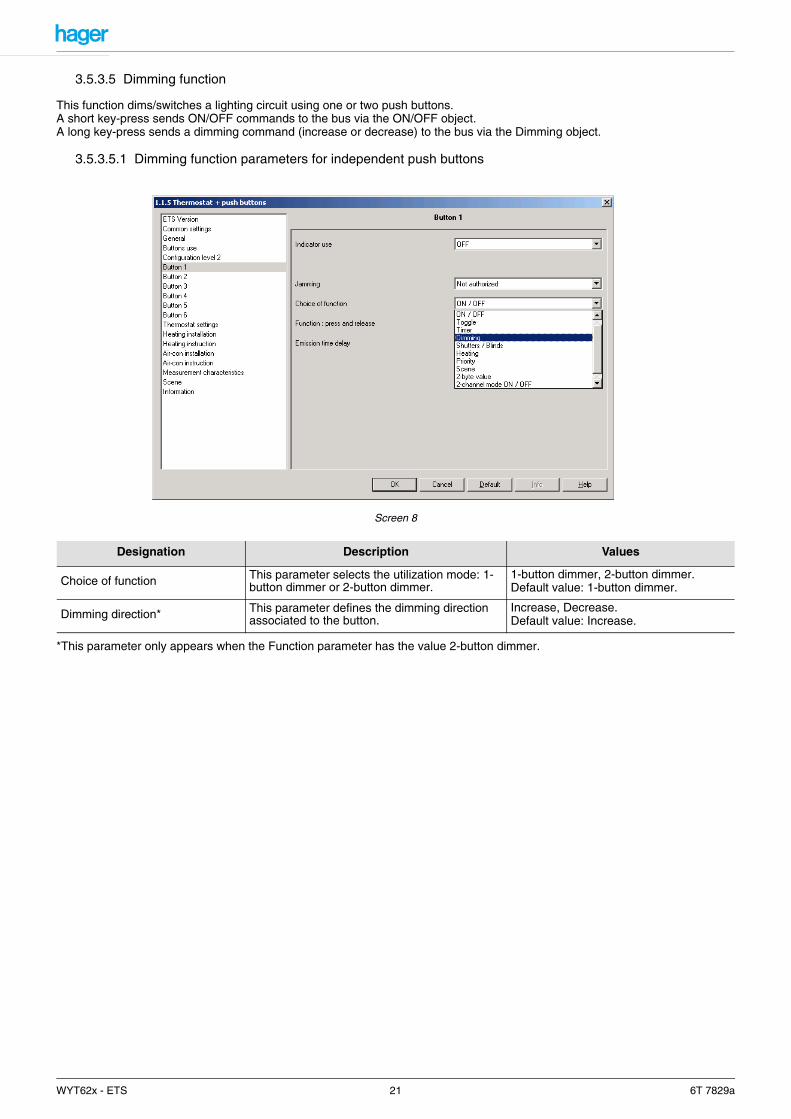
3.5.3.4 ON/OFF function parameters for linked push buttons
Screen 7
Designation Description Values
Function : press and release This parameter defines the commands sent when the push button is pressed and released.
Toggle / -, Time-limited toggle switch, -/Toggle.Default value: Toggle / -.Command when pressing/Command when releasing (" - " = No action).
Designation Description Values
Function left button / right buttonThis parameter defines the commands sent when the left button and the right button are pressed.
ON/OFF, OFF/ON, ON/ON, OFF/OFF.Default value: ON/OFF.
WYT62x - ETS 20 6T 7829a
3.5.3.5 Dimming function
This function dims/switches a lighting circuit using one or two push buttons.A short key-press sends ON/OFF commands to the bus via the ON/OFF object.A long key-press sends a dimming command (increase or decrease) to the bus via the Dimming object.
3.5.3.5.1 Dimming function parameters for independent push buttons
Screen 8
*This parameter only appears when the Function parameter has the value 2-button dimmer.
Designation Description Values
Choice of function This parameter selects the utilization mode: 1-button dimmer or 2-button dimmer.
1-button dimmer, 2-button dimmer.Default value: 1-button dimmer.
Dimming direction* This parameter defines the dimming direction associated to the button.
Increase, Decrease.Default value: Increase.
WYT62x - ETS 21 6T 7829a
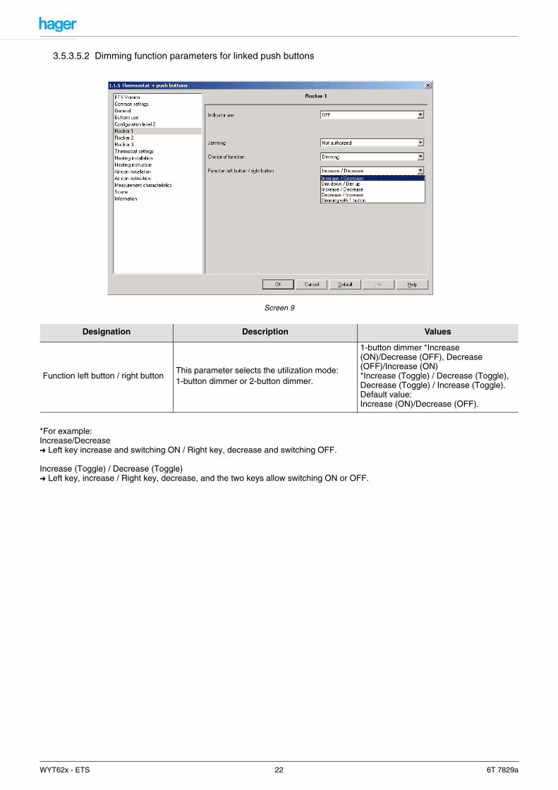
3.5.3.5.2 Dimming function parameters for linked push buttons
Screen 9
*For example:Increase/Decrease➜ Left key increase and switching ON / Right key, decrease and switching OFF.
Increase (Toggle) / Decrease (Toggle)➜ Left key, increase / Right key, decrease, and the two keys allow switching ON or OFF.
Designation Description Values
Function left button / right buttonThis parameter selects the utilization mode:1-button dimmer or 2-button dimmer.
1-button dimmer *Increase (ON)/Decrease (OFF), Decrease (OFF)/Increase (ON)*Increase (Toggle) / Decrease (Toggle), Decrease (Toggle) / Increase (Toggle).Default value:Increase (ON)/Decrease (OFF).
WYT62x - ETS 22 6T 7829a

3.5.3.6 Up/Down function
This function controls shutters or a blind using one or two push buttons. A long key-press sends raising or lowering commands to the bus via the Up/Down object. A short key-press sends stop or slat angle value commands to the bus via the Stop/Angle object.
3.5.3.6.1 Up/Down function parameters for independent push buttons
Screen 10
* Pressing the push button sends Up or Down commands to the bus via the Up/Down object. When the push button is released, a Stop command is sent via the Stop/Angle object.**This parameter is only visible if the Function parameter has the value: 2-button shutters/blinds or 2-button shutters/blinds with security function.
Designation Description Values
Choice of function This parameter selects the utilization mode.
1-button shutters/blinds (up/stop/down/stop)*Security function (dead man), Default value:Shutters/blinds with 1 button (up/stop/down/stop)
Function** This parameter defines the movement direction associated to the button.
Up, Down.Default value: Up.
WYT62x - ETS 23 6T 7829a

3.5.3.6.2 Up/Down function parameters for linked push buttons
Screen 11
*Pressing the linked push buttons (left or right) sends movement commands to the bus via the Up/Down object. When the linked push button is released, a Stop command is sent via the Stop/Angle object.**The left key and the right key have the same functions in this operation mode. In both cases, the Up/Stop/Down/Stop function is linked to the type of key-press (short key-press or long key-press).
3.5.3.7 Heating setpoint selection function
This function is used to select the setpoint for heating/air-conditioning.The 1-byte heating setpoint object sends the following values:
Designation Description Values
Function left button / right button Selects the Shutters/Blinds operating mode.
Shutters/BlindsDown/Up*Up/Down, with security function*Down/Up with security function**1-button shuttersDefault value: Down/Up with security function.
Values Product designation Icon
0 Auto
1 Comfort
2 Economy
3 Reduced (night)
4 Frost protection
WYT62x - ETS 24 6T 7829a
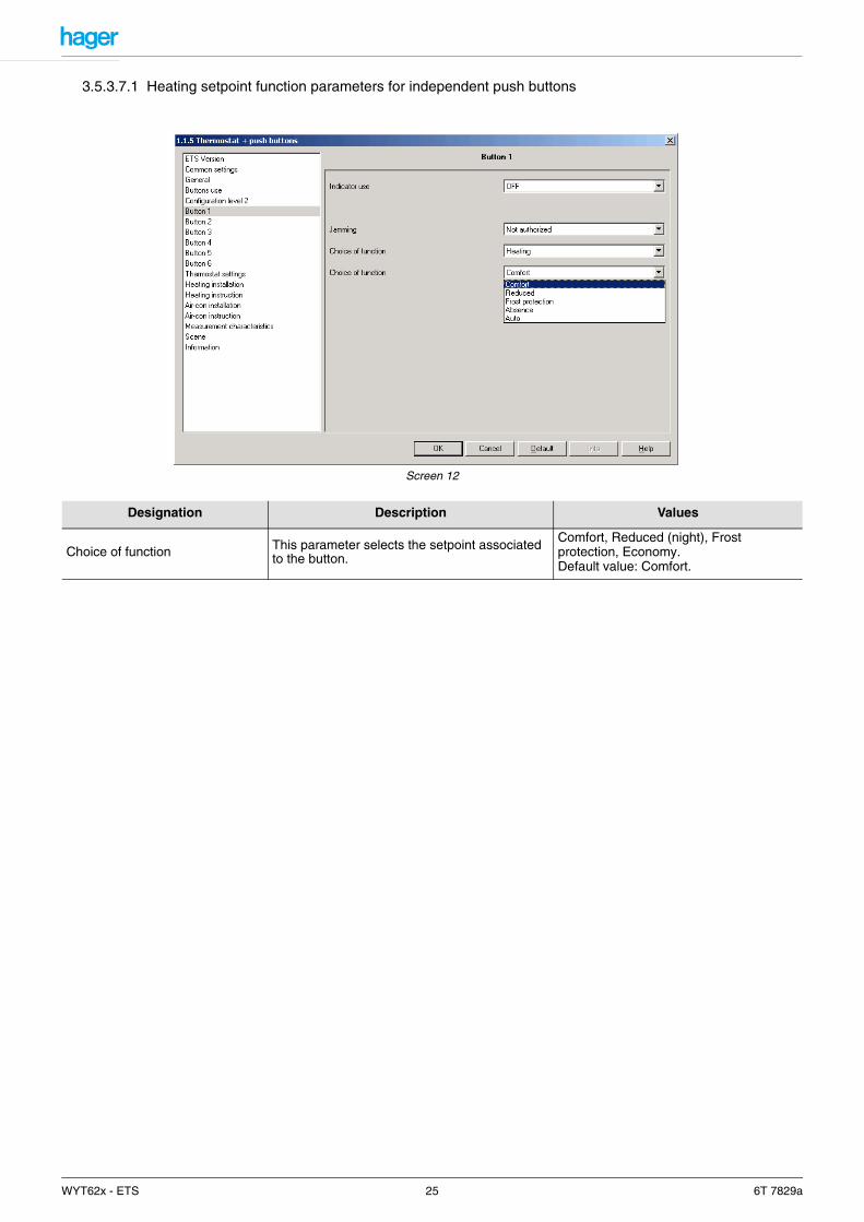
3.5.3.7.1 Heating setpoint function parameters for independent push buttons
Screen 12
Designation Description Values
Choice of function This parameter selects the setpoint associated to the button.
Comfort, Reduced (night), Frost protection, Economy.Default value: Comfort.
WYT62x - ETS 25 6T 7829a

3.5.3.7.2 Heating setpoint function parameters for linked push buttons
Screen 13
Designation Description Values
Function left button / right button This parameter defines the commands associated to the left button and the right button.
Comfort/Reduced (night), Reduced (night)/Comfort, Frost protection/Auto, Auto/Frost protection.Default value:Comfort/Reduced (night).
WYT62x - ETS 26 6T 7829a
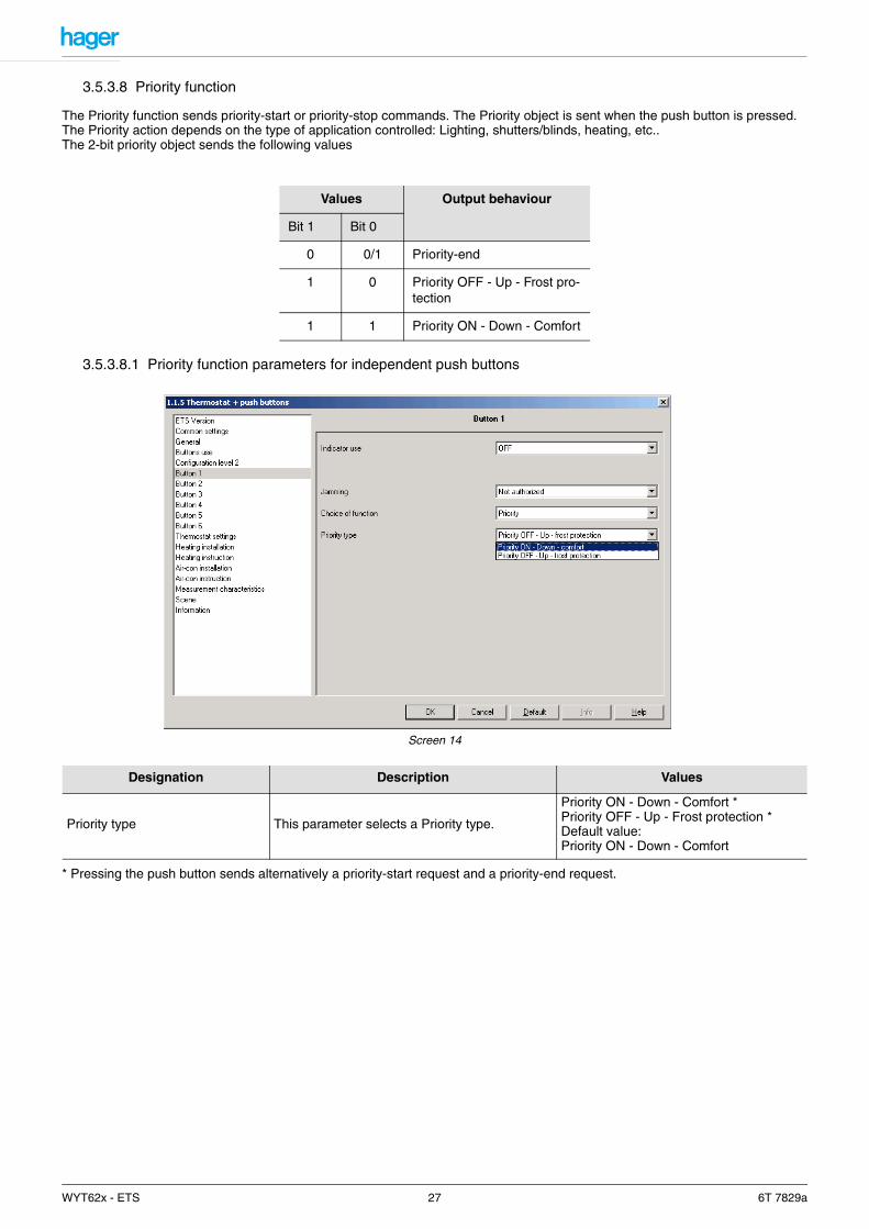
3.5.3.8 Priority function
The Priority function sends priority-start or priority-stop commands. The Priority object is sent when the push button is pressed. The Priority action depends on the type of application controlled: Lighting, shutters/blinds, heating, etc..The 2-bit priority object sends the following values
3.5.3.8.1 Priority function parameters for independent push buttons
Screen 14
* Pressing the push button sends alternatively a priority-start request and a priority-end request.
Values Output behaviour
Bit 1 Bit 0
0 0/1 Priority-end
1 0 Priority OFF - Up - Frost pro-tection
1 1 Priority ON - Down - Comfort
Designation Description Values
Priority type This parameter selects a Priority type.
Priority ON - Down - Comfort *Priority OFF - Up - Frost protection *Default value:Priority ON - Down - Comfort
WYT62x - ETS 27 6T 7829a
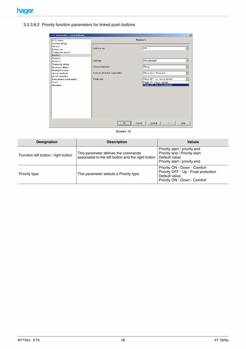
3.5.3.8.2 Priority function parameters for linked push buttons
Screen 15
Designation Description Values
Function left button / right button This parameter defines the commands associated to the left button and the right button.
Priority start / priority endPriority end / Priority startDefault value: Priority start / priority end
Priority type This parameter selects a Priority type.
Priority ON - Down - ComfortPriority OFF - Up - Frost protectionDefault value:Priority ON - Down - Comfort
WYT62x - ETS 28 6T 7829a
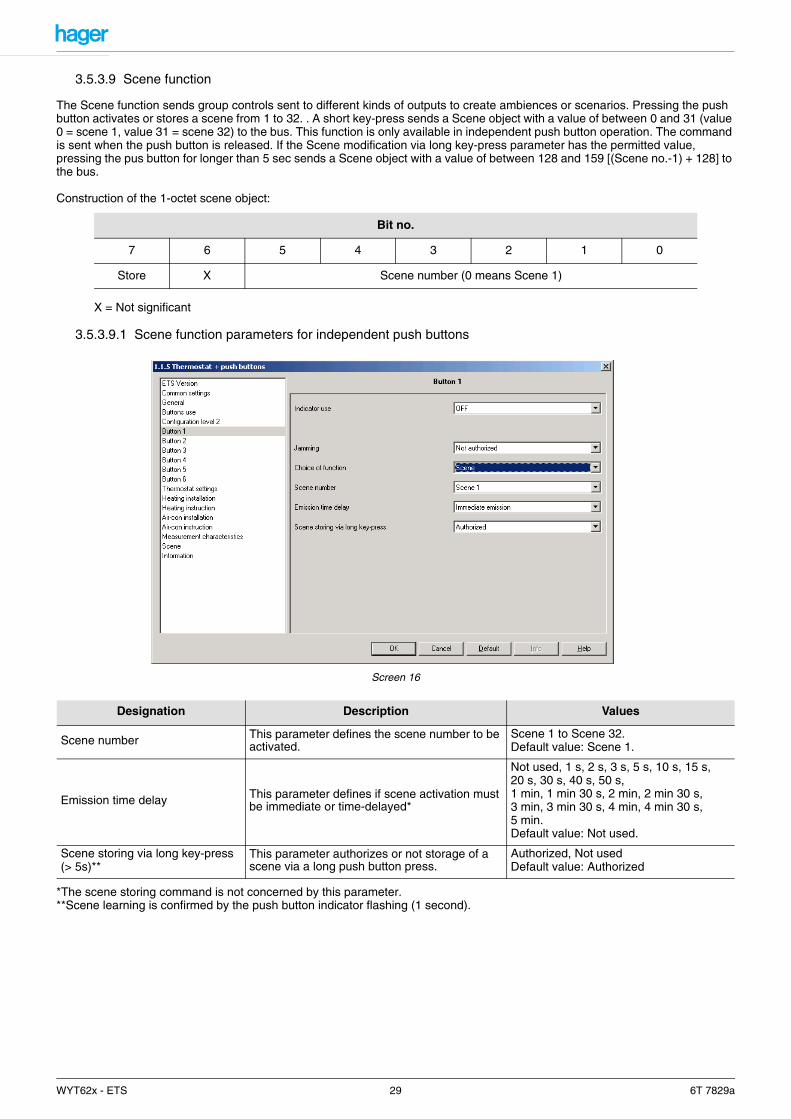
3.5.3.9 Scene function
The Scene function sends group controls sent to different kinds of outputs to create ambiences or scenarios. Pressing the push button activates or stores a scene from 1 to 32. . A short key-press sends a Scene object with a value of between 0 and 31 (value 0 = scene 1, value 31 = scene 32) to the bus. This function is only available in independent push button operation. The command is sent when the push button is released. If the Scene modification via long key-press parameter has the permitted value, pressing the pus button for longer than 5 sec sends a Scene object with a value of between 128 and 159 [(Scene no.-1) + 128] to the bus.
Construction of the 1-octet scene object:
X = Not significant
3.5.3.9.1 Scene function parameters for independent push buttons
Screen 16
*The scene storing command is not concerned by this parameter.**Scene learning is confirmed by the push button indicator flashing (1 second).
Bit no.
7 6 5 4 3 2 1 0
Store X Scene number (0 means Scene 1)
Designation Description Values
Scene number This parameter defines the scene number to be activated.
Scene 1 to Scene 32.Default value: Scene 1.
Emission time delay This parameter defines if scene activation must be immediate or time-delayed*
Not used, 1 s, 2 s, 3 s, 5 s, 10 s, 15 s, 20 s, 30 s, 40 s, 50 s,1 min, 1 min 30 s, 2 min, 2 min 30 s, 3 min, 3 min 30 s, 4 min, 4 min 30 s, 5 min.Default value: Not used.
Scene storing via long key-press (> 5s)**
This parameter authorizes or not storage of a scene via a long push button press.
Authorized, Not usedDefault value: Authorized
WYT62x - ETS 29 6T 7829a
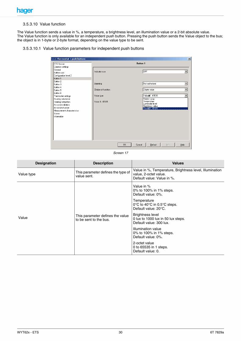
3.5.3.10 Value function
The Value function sends a value in %, a temperature, a brightness level, an illumination value or a 2-bit absolute value.The Value function is only available for an independent push button. Pressing the push button sends the Value object to the bus; the object is in 1-byte or 2-byte format, depending on the value type to be sent.
3.5.3.10.1 Value function parameters for independent push buttons
Screen 17
Designation Description Values
Value type This parameter defines the type of value sent.
Value in %, Temperature, Brightness level, Illumination value, 2-octet value.Default value: Value in %.
Value This parameter defines the value to be sent to the bus.
Value in %0% to 100% in 1% steps.Default value: 0%.
Temperature0°C to 40°C in 0.5°C steps.Default value: 20°C.
Brightness level0 lux to 1000 lux in 50 lux steps.Default value: 300 lux.
Illumination value0% to 100% in 1% steps.Default value: 0%.
2-octet value0 to 65535 in 1 steps.Default value: 0.
WYT62x - ETS 30 6T 7829a
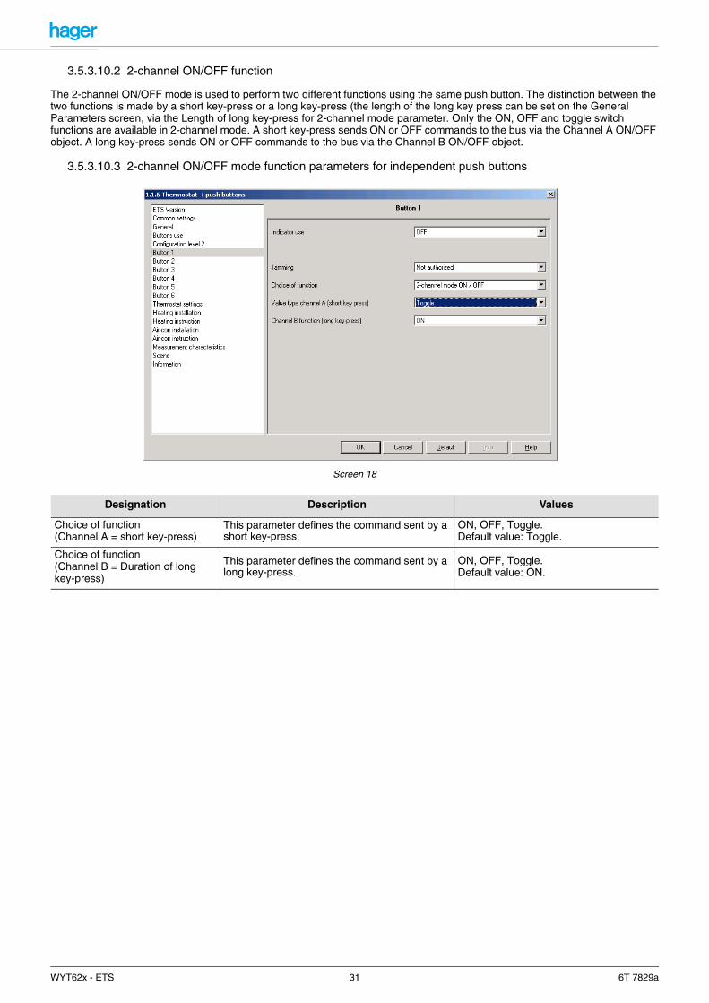
3.5.3.10.2 2-channel ON/OFF function
The 2-channel ON/OFF mode is used to perform two different functions using the same push button. The distinction between the two functions is made by a short key-press or a long key-press (the length of the long key press can be set on the General Parameters screen, via the Length of long key-press for 2-channel mode parameter. Only the ON, OFF and toggle switch functions are available in 2-channel mode. A short key-press sends ON or OFF commands to the bus via the Channel A ON/OFF object. A long key-press sends ON or OFF commands to the bus via the Channel B ON/OFF object.
3.5.3.10.3 2-channel ON/OFF mode function parameters for independent push buttons
Screen 18
Designation Description Values
Choice of function(Channel A = short key-press)
This parameter defines the command sent by a short key-press.
ON, OFF, Toggle.Default value: Toggle.
Choice of function(Channel B = Duration of long key-press)
This parameter defines the command sent by a long key-press.
ON, OFF, Toggle.Default value: ON.
WYT62x - ETS 31 6T 7829a

3.5.3.10.4 2-channel ON/OFF mode function parameters for linked push buttons
Screen 19
3.5.3.11 2-channel mode value function
The 2-channel value mode sends two different value commands using the same push button. The Value function is only available for an independent push button. The distinction between the two functions is made by a short key-press or a long key-press (the length of the long key-press is adjustable). A short key-press sends a value command to the bus via the Channel A Value object. A long key-press sends a value control to the bus via the Channel B Value object.
3.5.3.11.1 2-channel value mode function parameters for independent push buttons
Screen 20
Designation Description Values
Channel A function with short key-press Left button / Right button
This parameter defines the command sent by a short key-press on the left button and on the right button.
ON/OFF, OFF/ON, ON/ON, OFF/OFF.Default value: ON/OFF.
Channel B function with long key-press Left button / Right button
This parameter defines the command sent by a long key-press on the left button and on the right button.
ON/OFF, OFF/ON, ON/ON, OFF/OFF.Default value: ON/OFF.
WYT62x - ETS 32 6T 7829a
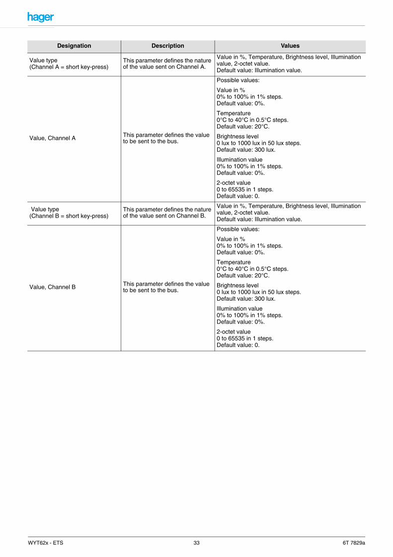
Designation Description Values
Value type(Channel A = short key-press)
This parameter defines the nature of the value sent on Channel A.
Value in %, Temperature, Brightness level, Illumination value, 2-octet value.Default value: Illumination value.
Value, Channel A This parameter defines the value to be sent to the bus.
Possible values:
Value in %0% to 100% in 1% steps.Default value: 0%.
Temperature0°C to 40°C in 0.5°C steps.Default value: 20°C.
Brightness level0 lux to 1000 lux in 50 lux steps.Default value: 300 lux.
Illumination value0% to 100% in 1% steps.Default value: 0%.
2-octet value0 to 65535 in 1 steps.Default value: 0.
Value type(Channel B = short key-press)
This parameter defines the nature of the value sent on Channel B.
Value in %, Temperature, Brightness level, Illumination value, 2-octet value.Default value: Illumination value.
Value, Channel B This parameter defines the value to be sent to the bus.
Possible values:
Value in %0% to 100% in 1% steps.Default value: 0%.
Temperature0°C to 40°C in 0.5°C steps.Default value: 20°C.
Brightness level0 lux to 1000 lux in 50 lux steps.Default value: 300 lux.
Illumination value0% to 100% in 1% steps.Default value: 0%.
2-octet value0 to 65535 in 1 steps.Default value: 0.
WYT62x - ETS 33 6T 7829a
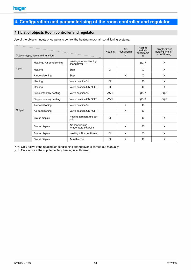
Use of the objects (inputs or outputs) to control the heating and/or air-conditioning systems.
(X)(1): Only active if the heating/air-conditioning changeover is carried out manually.(X)(2): Only active if the supplementary heating is authorized.
4. Configuration and parameterising of the room controller and regulator
4.1 List of objects Room controller and regulator
Objects (type, name and function)
HeatingAir-
conditioning
Heating and air-
conditioning
Single-circuit heating and air-
conditioning
Input
Heating / Air-conditioning Heating/air-conditioning changeover (X)(1) X
Heating Stop X X X
Air-conditioning Stop X X X
Output
Heating Valve position % X X X
Heating Valve position ON / OFF X X X
Supplementary heating Valve position % (X)(2) (X)(2) (X)(2)
Supplementary heating Valve position ON / OFF (X)(2) (X)(2) (X)(2)
Air-conditioning Valve position % X X
Air-conditioning Valve position ON / OFF X X
Status display Heating temperature set-point X X X
Status display Air-conditioning temperature set-point X X X
Status display Heating / Air-conditioning X X X X
Status display Actual mode X X X X
WYT62x - ETS 34 6T 7829a
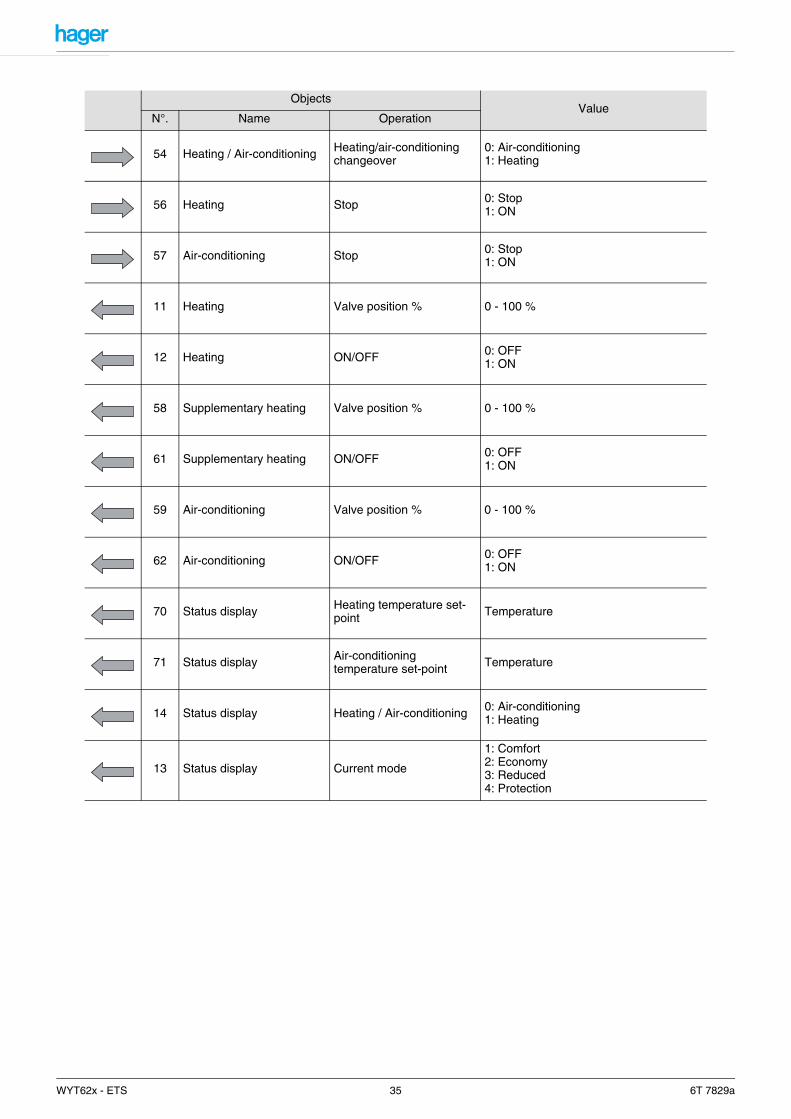
ObjectsValue
N°. Name Operation
54 Heating / Air-conditioning Heating/air-conditioning changeover
0: Air-conditioning1: Heating
56 Heating Stop 0: Stop1: ON
57 Air-conditioning Stop 0: Stop1: ON
11 Heating Valve position % 0 - 100 %
12 Heating ON/OFF 0: OFF1: ON
58 Supplementary heating Valve position % 0 - 100 %
61 Supplementary heating ON/OFF 0: OFF1: ON
59 Air-conditioning Valve position % 0 - 100 %
62 Air-conditioning ON/OFF 0: OFF1: ON
70 Status display Heating temperature set-point Temperature
71 Status display Air-conditioning temperature set-point Temperature
14 Status display Heating / Air-conditioning 0: Air-conditioning1: Heating
13 Status display Current mode
1: Comfort2: Economy3: Reduced4: Protection
WYT62x - ETS 35 6T 7829a

Use of the objects (inputs or outputs) to control the thermostat for heating or air-conditioning
*: All excepted the supplementary heating.
Objects (type, name and function)
Room transmitter type (Heating)
Room transmitter type (Air-conditioning)
Input
Thermostat Mode selection (Comfort, Eco,…) All* All
Thermostat Protection All* All
Thermostat Magnetic contact All* All
Thermostat Priority All* All
Thermostat Timer-controlled Comfort All* All
Thermostat Scene All* All
Thermostat Comfort temperature set-point All* All
Temperature Outside temperature All* All
Temperature Floor temperature
Only for the following transmitters: Heating floor (electrical or water) and Customized regulation.
Only for the following transmitters: Customized
setting.
Thermostat Jamming Always available
Temperature Ambient temperature All* All
Output
Status display Room temperature All* All
Status display Actual mode All* All
Status display Heating / Air-conditioning All* All
Fan Speed 1Only for the following
transmitters: Fan Convector and Customized regulation.
Only for the following transmitters: Fan Convector and Customized regulation.
WYT62x - ETS 36 6T 7829a
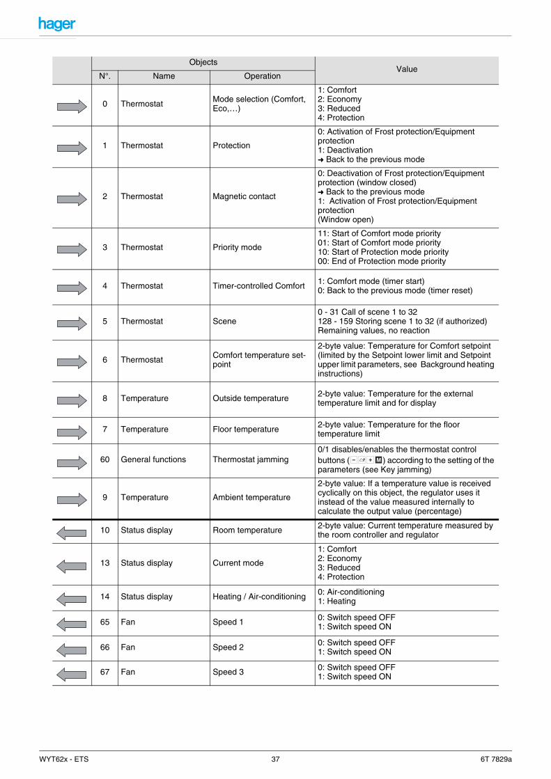
ObjectsValue
N°. Name Operation
0 Thermostat Mode selection (Comfort, Eco,…)
1: Comfort2: Economy3: Reduced4: Protection
1 Thermostat Protection
0: Activation of Frost protection/Equipment protection1: Deactivation➜ Back to the previous mode
2 Thermostat Magnetic contact
0: Deactivation of Frost protection/Equipment protection (window closed)➜ Back to the previous mode1: Activation of Frost protection/Equipment protection(Window open)
3 Thermostat Priority mode
11: Start of Comfort mode priority01: Start of Comfort mode priority10: Start of Protection mode priority00: End of Protection mode priority
4 Thermostat Timer-controlled Comfort 1: Comfort mode (timer start)0: Back to the previous mode (timer reset)
5 Thermostat Scene0 - 31 Call of scene 1 to 32128 - 159 Storing scene 1 to 32 (if authorized)Remaining values, no reaction
6 Thermostat Comfort temperature set-point
2-byte value: Temperature for Comfort setpoint (limited by the Setpoint lower limit and Setpoint upper limit parameters, see Background heating instructions)
8 Temperature Outside temperature 2-byte value: Temperature for the external temperature limit and for display
7 Temperature Floor temperature 2-byte value: Temperature for the floor temperature limit
60 General functions Thermostat jamming0/1 disables/enables the thermostat control buttons ( ) according to the setting of the parameters (see Key jamming)
9 Temperature Ambient temperature
2-byte value: If a temperature value is received cyclically on this object, the regulator uses it instead of the value measured internally to calculate the output value (percentage)
10 Status display Room temperature 2-byte value: Current temperature measured by the room controller and regulator
13 Status display Current mode
1: Comfort2: Economy3: Reduced4: Protection
14 Status display Heating / Air-conditioning 0: Air-conditioning1: Heating
65 Fan Speed 1 0: Switch speed OFF1: Switch speed ON
66 Fan Speed 2 0: Switch speed OFF1: Switch speed ON
67 Fan Speed 3 0: Switch speed OFF1: Switch speed ON
+- M
WYT62x - ETS 37 6T 7829a
This area of the WDL620A application allows setting the following parameters:
- Regulation type (heating/air-conditioning) selection- Use of the control push buttons of the regulator ( )- Cyclic emission of the current setpoint and of the regulation type Heating or Air-conditionning- Jamming of the control push buttons of the regulator- Valve protection
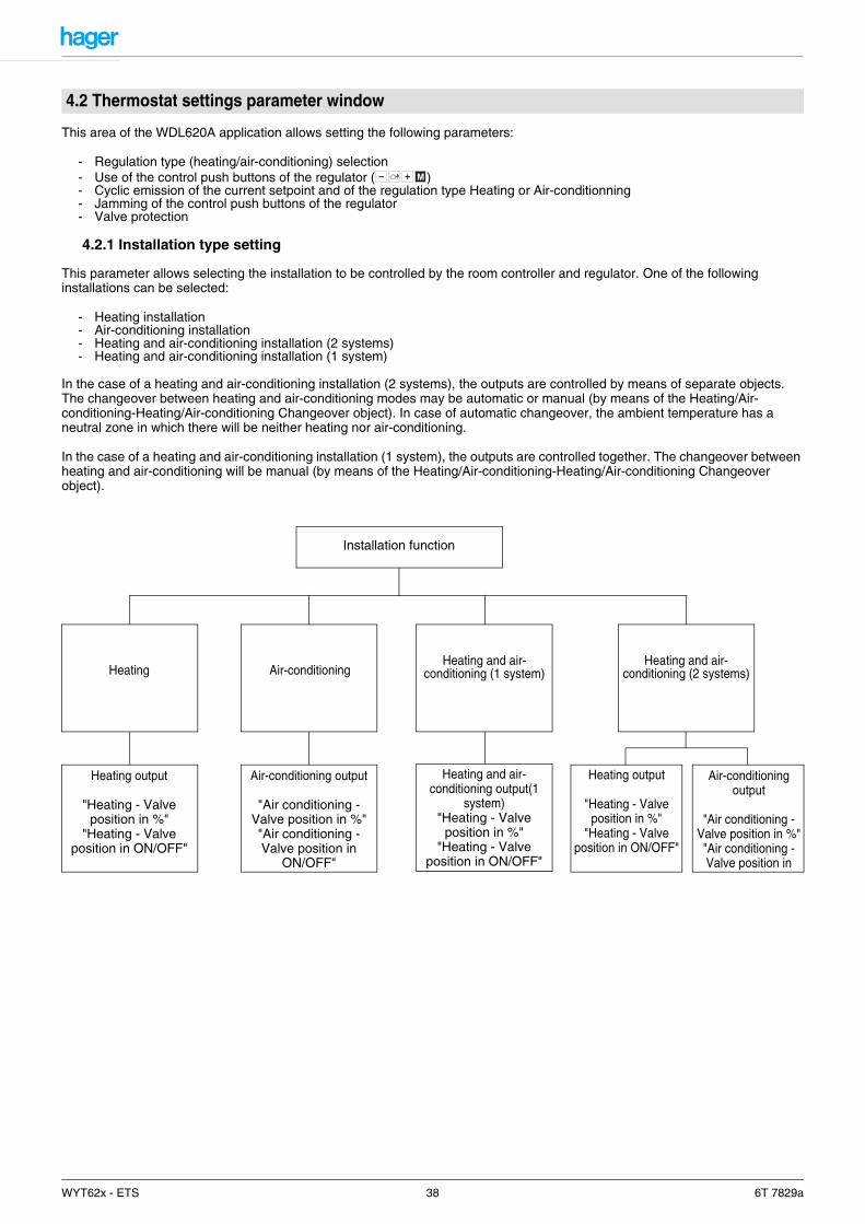
4.2.1 Installation type setting
This parameter allows selecting the installation to be controlled by the room controller and regulator. One of the following installations can be selected:
- Heating installation- Air-conditioning installation- Heating and air-conditioning installation (2 systems)- Heating and air-conditioning installation (1 system)
In the case of a heating and air-conditioning installation (2 systems), the outputs are controlled by means of separate objects. The changeover between heating and air-conditioning modes may be automatic or manual (by means of the Heating/Air-conditioning-Heating/Air-conditioning Changeover object). In case of automatic changeover, the ambient temperature has a neutral zone in which there will be neither heating nor air-conditioning.
In the case of a heating and air-conditioning installation (1 system), the outputs are controlled together. The changeover between heating and air-conditioning will be manual (by means of the Heating/Air-conditioning-Heating/Air-conditioning Changeover object).
4.2 Thermostat settings parameter window
+- M
Installation function
Air-conditioningHeatingHeating and air-
conditioning (1 system)
Heating output
"Heating - Valve position in %"
"Heating - Valve position in ON/OFF"
Air-conditioning output
"Air conditioning - Valve position in %""Air conditioning - Valve position in
ON/OFF"
Heating and air-conditioning output(1
system)"Heating - Valve
position in %""Heating - Valve
position in ON/OFF"
Heating and air-conditioning (2 systems)
Air-conditioning output
"Air conditioning - Valve position in %""Air conditioning - Valve position in
Heating output
"Heating - Valve position in %"
"Heating - Valve position in ON/OFF"
WYT62x - ETS 38 6T 7829a

Screen 21Installation:
* This parameter only is visible if the parameter Air-conditioning type is set to Heating and Air-conditioning (2 systems)
Designation Description Values
Regulation functions used
This parameter allows selecting the installation to be controlled by the room controller and regulator. The output objects for heating/air-conditioning will be generated depending on this parameter (see the presentation on the previous page).
Heating,Air-conditioning,Heating and air-conditioning (2 systems), Heating and air-conditioning (1 system).
Default value: Heating and air-conditioning (1 system).
Changeover Heating / Air-conditioning*
This parameter defines whether the changeover between heating and air-conditioning will be automatic (depending on the ambient temperature measured) or manual by receiving a group address on the Heating/Air-conditioning-Changeover Heating/Air-conditioning object (1 = heating; 0 = air-conditioning).
Manual, Automatic.Default value: Automatic.
WYT62x - ETS 39 6T 7829a

4.2.2 Use of the control push buttons of the regulator ( )
The parameters Regulator control push buttons allow acting upon the operation of the four control push buttons ( ) of the regulator.
Screen 22
Designation Description Values
PB + and -
Buttons and of the regulator allow modifying the setpoints defined with the ETS.This parameter defines whether this modification is allowed or not and, if it is allowed, the range of the modification.
Not usedSetting instruction (5 to 40°C), Deviation (+/-1°C), Deviation (+/-2°C), Deviation (+/-3°C).
Default value: Setting instruction (5 to 40°C).
PB presence(Duration for Comfort)
The button of the regulator allows switching to the Standby mode.
This parameter allows defining if the changeover possibility is unlimited, time-limited or not used.
Not used, Unlimited, 15 min, 20 min, 30 min, 1 h, 1 h 30 min, 2 h, 2 h 30 min, 3 h, 3 h 30 min, 4 h, 5 h, 6 h, 12 h, 24 h.
Default value: 1 h.
PB Mode
The button of the regulator allows switching the regulator between the modes: Reduced, Comfort, Standby, and Comfort priority and Frost protection priority.
This parameter allow defining whether the mode changeover using the button is Authorized or Not used.
Not used, Authorized.Default value: Authorized.
+- M
+- M
+ -
M
WYT62x - ETS 40 6T 7829a
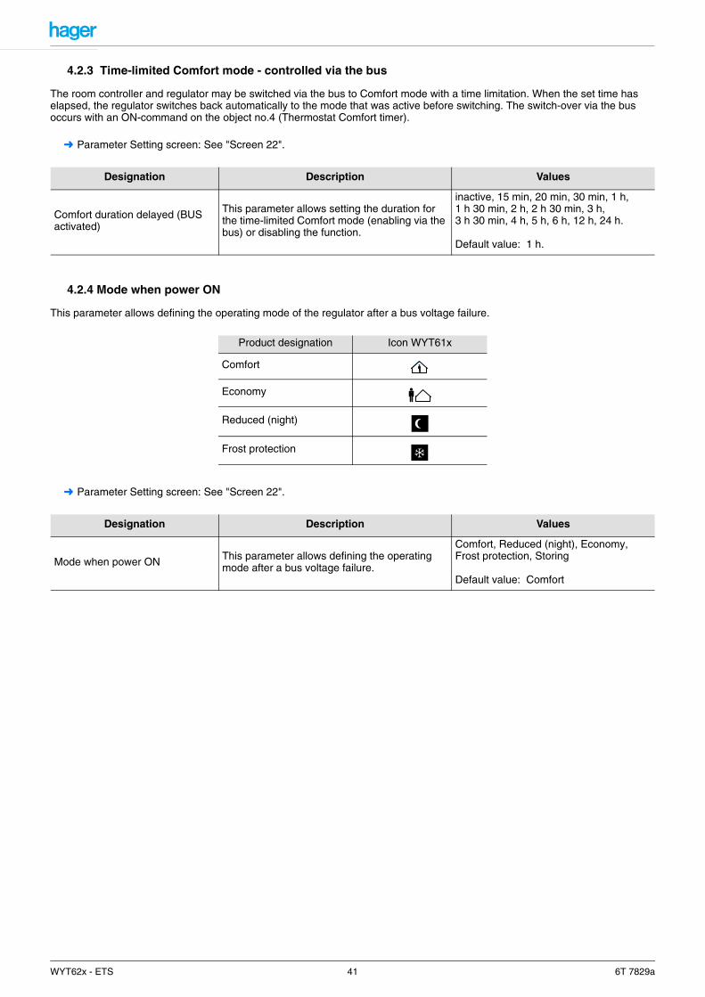
4.2.3 Time-limited Comfort mode - controlled via the bus
The room controller and regulator may be switched via the bus to Comfort mode with a time limitation. When the set time has elapsed, the regulator switches back automatically to the mode that was active before switching. The switch-over via the bus occurs with an ON-command on the object no.4 (Thermostat Comfort timer).
➜ Parameter Setting screen: See "Screen 22".
4.2.4 Mode when power ON
This parameter allows defining the operating mode of the regulator after a bus voltage failure.
➜ Parameter Setting screen: See "Screen 22".
Designation Description Values
Comfort duration delayed (BUS activated)
This parameter allows setting the duration for the time-limited Comfort mode (enabling via the bus) or disabling the function.
inactive, 15 min, 20 min, 30 min, 1 h, 1 h 30 min, 2 h, 2 h 30 min, 3 h, 3 h 30 min, 4 h, 5 h, 6 h, 12 h, 24 h.
Default value: 1 h.
Product designation Icon WYT61x
Comfort
Economy
Reduced (night)
Frost protection
Designation Description Values
Mode when power ON This parameter allows defining the operating mode after a bus voltage failure.
Comfort, Reduced (night), Economy, Frost protection, Storing
Default value: Comfort
WYT62x - ETS 41 6T 7829a
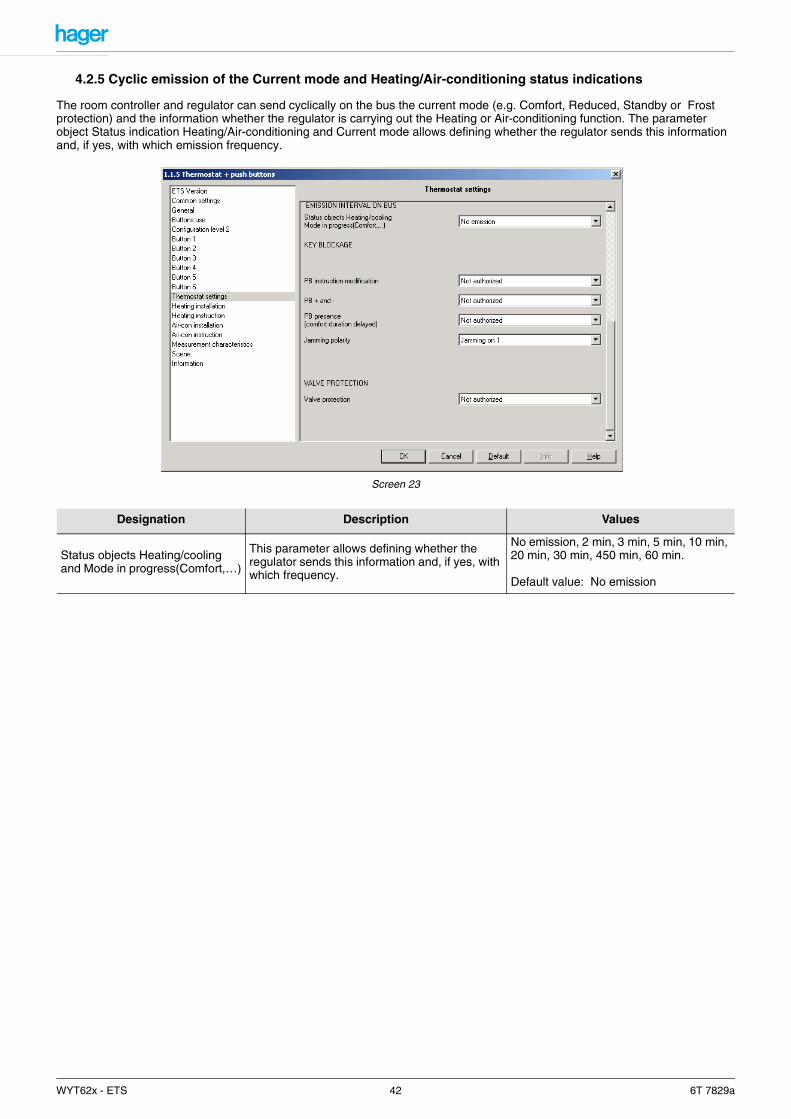
4.2.5 Cyclic emission of the Current mode and Heating/Air-conditioning status indications
The room controller and regulator can send cyclically on the bus the current mode (e.g. Comfort, Reduced, Standby or Frost protection) and the information whether the regulator is carrying out the Heating or Air-conditioning function. The parameter object Status indication Heating/Air-conditioning and Current mode allows defining whether the regulator sends this information and, if yes, with which emission frequency.
Screen 23
Designation Description Values
Status objects Heating/cooling and Mode in progress(Comfort,…)
This parameter allows defining whether the regulator sends this information and, if yes, with which frequency.
No emission, 2 min, 3 min, 5 min, 10 min, 20 min, 30 min, 450 min, 60 min.
Default value: No emission
WYT62x - ETS 42 6T 7829a
4.2.6 Jamming the buttons
The object General - Thermostat jamming allows jamming the control push buttons of the Regulator ( ). The Key blockage parameters allow defining which push buttons are to be jammed. The value with which the jamming/authorization of the push buttons occurs can also be defined.
➜ Parameter Setting screen: See "Screen 23".
4.2.7 Valve protection
The regulator can actuate the valves connected to the controlled outputs periodically, if they are not in use, to prevent them from jamming.
➜ Parameter Setting screen: See "Screen 23".
Designation Description Values
PB + and -The function of the and push buttons can be jammed via the bus. This parameter allows defining whether jamming is used or not.
Not used, AuthorizedDefault value: Not used.
PB ModeThe function of the push button can be jammed via the bus. This parameter allows defining whether jamming is used or not.
Not used, AuthorizedDefault value: Not used.
PB presence (comfort duration delayed)
The function of the push button can be jammed via the bus. This parameter allows defining whether jamming is used or not.
Not used, AuthorizedDefault value: Not used.
Jamming polarity This parameter allows defining the value with which the jamming of the buttons is activated.
Jamming set to 0, Jamming set to 1.Default value: Jamming set to 1.
Designation Description Values
Valve protectionThis parameter allows defining whether the Valve protection function is Authorized or Not used.
Not used, Authorized.Default value: Not used.
+- M
+ -
M
WYT62x - ETS 43 6T 7829a

These parameters only are visible if the Installation-Air conditioning type parameter is set to one of the values:
- Heating- Heating and air-conditioning (2 systems)- Heating and air-conditioning (1 system)
in the area Thermostat settings.
4.3.1 Installation characteristics
The room controller and regulator allows controlling a background heating and a supplementary heating. The regulator may be adjusted according to the characteristics of the heating installation either by means of a selection among various heating types or by means of the setting of the regulation parameters.
The following heating types are available for selection for the backgroung heating:
Electrical heating- Electrical wall transmitter- Electrical underfloor heating
Hot water heating- Hot water radiator- Floor- Fan Convector
Customized installationIn case of a customized installation, the following parameters must be set:
- Proportional band- Integral period- Shift period- Chrono-proportional cycle
If a supplementary heating is integrated in the installation, the following parameters must also be set:- Comfort temperature reduction for the regulation of the supplementary heating- Setting type (2 point or constant cycle time)
4.3 Heating installation parameters
Heating
Background heating
Hot water heating:- Radiator- Heating floor- Fan Convector
Customized settingElectrical heating:
- Wall transmitter- Electrical underfloor hea-
ting
Supplementary heating
WYT62x - ETS 44 6T 7829a

Use of the room controller and regulator with a TXA output module.
Use of the room controller and regulator with a proportional valve actuator.
The ON/OFF output (object: Heating - Valve position ON / OFF) is only required in connection with a single output module (without Heating function).
Ambient temperature thermostat WDL610A Output module TXAOutput module TXA
Output (%)Heating - Valve position in
ON/OFFHeating - Valve position in
Heating input (%)Convector Thermal valve ON/OFF
The output performs a one-pulse wide modulation (PWM) to implement the percentual value.Cycle time must be set for this PWM.
Ambient temperature thermostat WDL610A Output module TXAProportional valve
actuator
Output (%)Heating - Valve position in
ON/OFFHeating - Valve position in
Heating input (%)
WYT62x - ETS 45 6T 7829a

4.3.1.1 Selection of the Room transmitter type and activation of the supplementary heating
The Room transmitter type parameter allows selecting the type of the installed background heating. Independently of this, a supplementary heating can also be activated.
Screen 24
Designation Description Values
Room transmitter typeThis parameter allows selecting the type of the installed heating and/or air-conditioning installation.
Radiator, Hot water underfloor heating, Electrical wall transmitter, Electrical underfloor heating, Fan Convector, Customized setting.
Default value: Radiator.
Supplementary heating
This parameter enables (Authorized) or disables (Not used) the control of the supplementary heating by the regulator.
Refer to Supplementary heating settings for the setting of the parameters of the supplementary heating.
Not used, Authorized.Default value: Authorized.
WYT62x - ETS 46 6T 7829a

4.3.1.2 External temperature and floor temperature limit
A power limitation function can be activated depending on the room transmitter type used. Two power limitation functions are available:
1. Limitation according to the outside temperature: available in case of an electrical heating and for customized regulation. The function limits the heating power called for by the regulator according to the outside temperature. The Limitation function is controlled by the Outside temperature object.
2. The temperatures required for the limitation can be monitored. If no new value is received within the monitoring time, the power limitation is stopped. (See 4.10 "Parameter value Measurement characteristics" Page 59)
4.3.1.2.1 External temperature limit
The Outside temperature limit function is available in case of an electrical heating and for customized regulation. The function limits the heating power called for according to the outside temperature. It is controlled by the Outside temperature object. The limitation curve of the heating power called for according to the outside temperature for a fixed setpoint is shown on the following diagram:
Calculation method:Te: Outside temperatureTc: Temperature setpointD: Delta of 3°KP: Variation range of 27°K
If Te >= Tc+D, the limitation is at its maximum (the Heating output is set to the value 0%) or, if Te < (Tc+D)-P, the limitation is equal to zero
ELSE limitation is calculated according to the formula:
Note: The Outside temperature limit function does not limit the power supplied by the supplementary heating.
T° setpoint Outside T° Authorized power Comment
20°C 25°C 0% Maximum limitation
20°C 10°C 48% /
20°C -7°C 100% Zero limitation
0%
100%
Authorized power
Delta set to 3°K
Outside T°
T° setpoint
Fluctuation range set to 27°K
Tc D+( ) Te+P
----------------------------------
WYT62x - ETS 47 6T 7829a
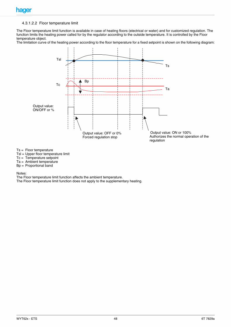
4.3.1.2.2 Floor temperature limit
The Floor temperature limit function is available in case of heating floors (electrical or water) and for customized regulation. The function limits the heating power called for by the regulator according to the outside temperature. It is controlled by the Floor temperature object.The limitation curve of the heating power according to the floor temperature for a fixed setpoint is shown on the following diagram:
Ts = Floor temperatureTsl = Upper floor temperature limitTc = Temperature setpointTa = Ambient temperatureBp = Proportional band
Notes:The Floor temperature limit function affects the ambient temperature.The Floor temperature limit function does not apply to the supplementary heating.
Output value: OFF or 0%Forced regulation stop
Tsl
TcBp
Ts
Ta
Output value:ON/OFF or %
Output value: ON or 100%Authorizes the normal operation of the regulation
WYT62x - ETS 48 6T 7829a
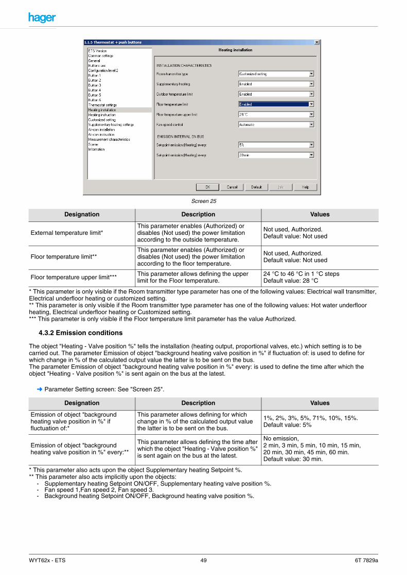
Screen 25
* This parameter is only visible if the Room transmitter type parameter has one of the following values: Electrical wall transmitter, Electrical underfloor heating or customized setting.** This parameter is only visible if the Room transmitter type parameter has one of the following values: Hot water underfloor heating, Electrical underfloor heating or Customized setting.*** This parameter is only visible if the Floor temperature limit parameter has the value Authorized.
4.3.2 Emission conditions
The object "Heating - Valve position %" tells the installation (heating output, proportional valves, etc.) which setting is to be carried out. The parameter Emission of object "background heating valve position in %" if fluctuation of: is used to define for which change in % of the calculated output value the latter is to be sent on the bus. The parameter Emission of object "background heating valve position in %" every: is used to define the time after which the object "Heating - Valve position %" is sent again on the bus at the latest.
➜ Parameter Setting screen: See "Screen 25".
* This parameter also acts upon the object Supplementary heating Setpoint %.** This parameter also acts implicitly upon the objects:
- Supplementary heating Setpoint ON/OFF, Supplementary heating valve position %.- Fan speed 1,Fan speed 2, Fan speed 3.- Background heating Setpoint ON/OFF, Background heating valve position %.
Designation Description Values
External temperature limit*This parameter enables (Authorized) or disables (Not used) the power limitation according to the outside temperature.
Not used, Authorized.Default value: Not used
Floor temperature limit**This parameter enables (Authorized) or disables (Not used) the power limitation according to the floor temperature.
Not used, Authorized.Default value: Not used
Floor temperature upper limit*** This parameter allows defining the upper limit for the Floor temperature.
24 °C to 46 °C in 1 °C stepsDefault value: 28 °C
Designation Description Values
Emission of object "background heating valve position in %" if fluctuation of:*
This parameter allows defining for which change in % of the calculated output value the latter is to be sent on the bus.
1%, 2%, 3%, 5%, 71%, 10%, 15%.Default value: 5%
Emission of object "background heating valve position in %" every:**
This parameter allows defining the time after which the object "Heating - Valve position %" is sent again on the bus at the latest.
No emission,2 min, 3 min, 5 min, 10 min, 15 min, 20 min, 30 min, 45 min, 60 min.Default value: 30 min.
WYT62x - ETS 49 6T 7829a

4.3.3 Fan speed control
When the room transmitter is a fan converter, the fan speed can be controlled automatically or manually by the aid of the buttons 3 and 6 of the thermostat.
The button 6 allows activating or deactivating the fan. Is the fan is unused the LED 6 is OFF. The LED 6 is green for cooling and red for heating.
The button 5 is used to change the fan speed. Three speeds are possible: Speed 1, Speed 2 and Speed 3 (object Speed 1 to Speed 3). Depressing button 5 cycles trough the 3 available speeds.("Speed 1", "Speed 2", "Speed 3"...).
The selected speed is temporarily displayed on the LCD wiht SP1 (2, 3) and by the aid of the LED 5, 3 and 1.
In case of automatic control, the buttons 5 and 6 are inhibited. The key blinks 3 seconds when they are used.
Screen 26
Speed LEDs LED color
1 5 ON Green when cooling and red when heating
2 5 and 3 ON Green when cooling and red when heating
3 5, 3 and 1 are ON Green when cooling and red when heating
Designation Description Values
Fan speed control This parameter defines the way the fan speed control is used.
AutomaticStopSpeed 1Speed 2Speed 3
WYT62x - ETS 50 6T 7829a

4.4 Background heating instructions parameter
The room controller and regulator regulates the temperature according to the set mode (Comfort, Standby, Reduced, Equipment protection). The modes are activated by means of various objects (see also 4.1 "List of objects Room controller and regulator" Page 34)
The Temperature setpoints for the modes can be set under this parameter item with the ETS.The temperature setpoints for the Standby and Reduced modes are relative with respect to the Comfort temperature setpoint. Thus, in case of a change of the Comfort temperature setpoint, the temperature setpoints of the Standby and Reduced modes are changed automatically. The temperature setpoint for the Comfort mode can also be set via the bus (Thermostats - Comfort temperature setpoint).The temperature setpoints for all modes can be limited using the Set-point lower limit and Set-point upper limit parameters.
Screen 27
Objects (type, name and function)
Comfort Reduced Economy Protection
Input
Thermostat Mode selection (Comfort, Eco,…) X X X X
Thermostat Priority X X
Thermostat Protection X
Thermostat Timer-controlled Comfort X
Thermostat Scene X X X X
Thermostat Magnetic contact X
Designation Description Values
Comfort This parameter allows setting the Comfort temperature setpoint.
10°C to 30°C in 1°C steps.Default value: 20°C.
Eco reductionThis parameter allows setting the temperature difference with respect to the Comfort temperature setpoint.
-0.5°C, -1.0°C, -1.5°C, -2.0°C, -2.5°C, -3.0°C, -3.5°C, -4.0°C.Default value: -1.0°C.
Reduction for ReducedThis parameter allows setting the temperature difference with respect to the Comfort temperature setpoint.
-2°C, -3°C, -4°C, -5°C, -6°C, -7°C, -8°C.Default value: -4°C.
Frost protection This parameter allows setting the temperature setpoint for Frost protection.
5°C, 6°C, 7°C, 8°C, 9°C, 10°C, 11°C, 12°C.Default value: 8°C.
Set-point lower limit This parameter allows setting a lower limit for the Comfort, Standby and Reduced setpoints.
5°C, 6°C, 7°C, 8°C, 9°C, 10°C, 11°C, 12°C, 13°C, 14°C, 15°C,.Default value: 5°C.
Set-point upper limit This parameter allows setting a lower limit for the Comfort, Standby and Reduced setpoints.
15°C, 16°C, 17°C, 18°C, 19°C, 20°C, 21°C, 22°C, 23°C, 24°C, 25°C, 26°C, 27°C, 28°C, 29°C, 30°C.Default value: 30°C.
WYT62x - ETS 51 6T 7829a

4.5 Parameterising of the Supplementary heating
These parameters are only visible if, in Heating installation, the Supplementary heating parameter is set to the value Authorized. The room controller and regulator can control a supplementary heating. The setpoint for the supplementary heating is relative with respect to the setpoint of the active mode. The difference between the background heating setpoint and the supplementary heating setpoint is defined with the parameter Reduction for supplementary heating.The output values for the supplementary stage are sent on the bus via the objects Supplementary heating - Valve position in % and Supplementary heating - Valve position ON / OFF.
Diagram showing the operation of the regulation of the supplementary heating.
The Setting type of the supplementary stage can be set either to 2 point or to Constant cycle time.In case of 2 point setting, the regulator only sends the valve positions 0% and 100%, or ON or OFF.In case of Constant cycle time setting, the regulator calculates cyclically a new output value in the range between 0 and 100.
Screen 28
Supplementary heating instructions
Regulator setting for supplementary heating
Designation Description Values
Reduction for supplementary heating
Supplementary heating setpoint = current Background heating setpoint- Reduction for supplementary heating.
1.0°C, 1.5°C, 2.0°C, 2.5°C, 3.0°C, 3.5°C, 4.0°C.Default value: 1.0°C
Emission on the % or ON/OFF output: Background + supplementary heating
Emission on the % or ON/OFF output: Background heating
Backgroundheating
instructions
Supplementaryheating
instructions
Value of the Reduction for supplementary heating parameter
WYT62x - ETS 52 6T 7829a
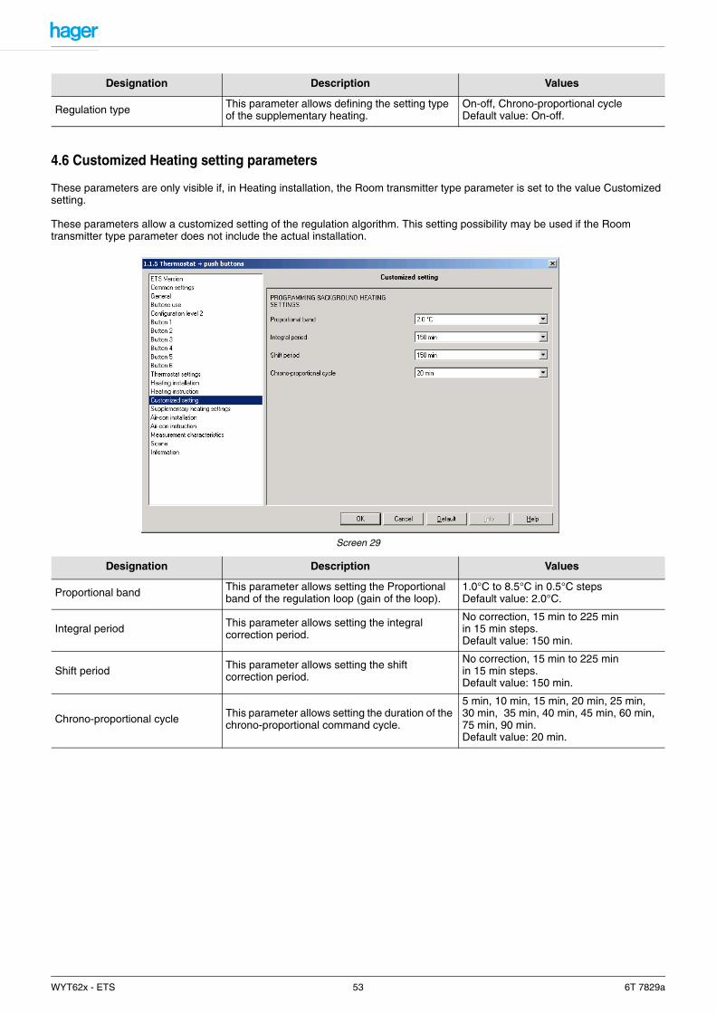
4.6 Customized Heating setting parameters
These parameters are only visible if, in Heating installation, the Room transmitter type parameter is set to the value Customized setting.
These parameters allow a customized setting of the regulation algorithm. This setting possibility may be used if the Room transmitter type parameter does not include the actual installation.
Screen 29
Designation Description Values
Regulation type This parameter allows defining the setting type of the supplementary heating.
On-off, Chrono-proportional cycleDefault value: On-off.
Designation Description Values
Proportional band This parameter allows setting the Proportional band of the regulation loop (gain of the loop).
1.0°C to 8.5°C in 0.5°C stepsDefault value: 2.0°C.
Integral period This parameter allows setting the integral correction period.
No correction, 15 min to 225 min in 15 min steps.Default value: 150 min.
Shift period This parameter allows setting the shift correction period.
No correction, 15 min to 225 min in 15 min steps.Default value: 150 min.
Chrono-proportional cycle This parameter allows setting the duration of the chrono-proportional command cycle.
5 min, 10 min, 15 min, 20 min, 25 min, 30 min, 35 min, 40 min, 45 min, 60 min, 75 min, 90 min.Default value: 20 min.
WYT62x - ETS 53 6T 7829a
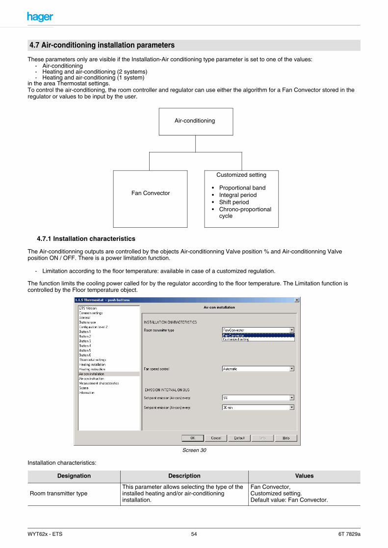
These parameters only are visible if the Installation-Air conditioning type parameter is set to one of the values:- Air-conditioning- Heating and air-conditioning (2 systems)- Heating and air-conditioning (1 system)
in the area Thermostat settings.To control the air-conditioning, the room controller and regulator can use either the algorithm for a Fan Convector stored in the regulator or values to be input by the user.
4.7.1 Installation characteristics
The Air-conditionning outputs are controlled by the objects Air-conditionning Valve position % and Air-conditionning Valve position ON / OFF. There is a power limitation function.
- Limitation according to the floor temperature: available in case of a customized regulation.
The function limits the cooling power called for by the regulator according to the floor temperature. The Limitation function is controlled by the Floor temperature object.
Screen 30
Installation characteristics:
4.7 Air-conditioning installation parameters
Designation Description Values
Room transmitter typeThis parameter allows selecting the type of the installed heating and/or air-conditioning installation.
Fan Convector,Customized setting.Default value: Fan Convector.
Customized setting
• Proportional band• Integral period• Shift period• Chrono-proportional
cycle
Air-conditioning
Fan Convector
WYT62x - ETS 54 6T 7829a
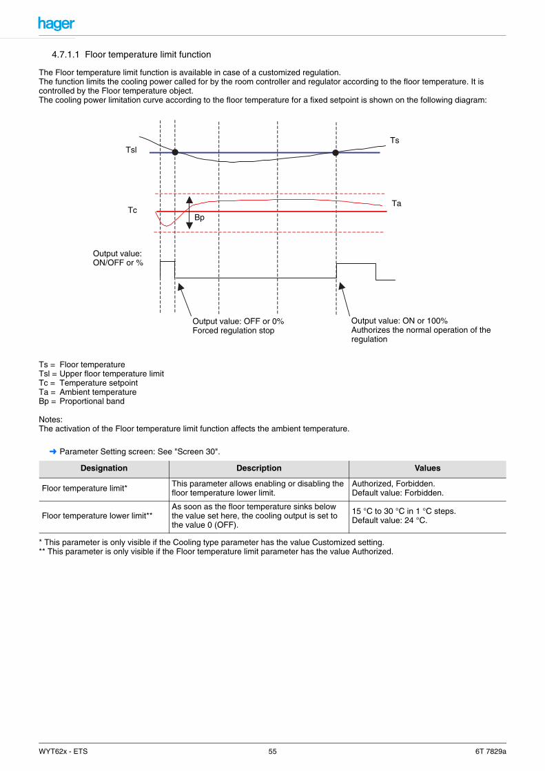
4.7.1.1 Floor temperature limit function
The Floor temperature limit function is available in case of a customized regulation.The function limits the cooling power called for by the room controller and regulator according to the floor temperature. It is controlled by the Floor temperature object. The cooling power limitation curve according to the floor temperature for a fixed setpoint is shown on the following diagram:
Ts = Floor temperatureTsl = Upper floor temperature limitTc = Temperature setpointTa = Ambient temperatureBp = Proportional band
Notes:The activation of the Floor temperature limit function affects the ambient temperature.
➜ Parameter Setting screen: See "Screen 30".
* This parameter is only visible if the Cooling type parameter has the value Customized setting.** This parameter is only visible if the Floor temperature limit parameter has the value Authorized.
Designation Description Values
Floor temperature limit* This parameter allows enabling or disabling the floor temperature lower limit.
Authorized, Forbidden.Default value: Forbidden.
Floor temperature lower limit**As soon as the floor temperature sinks below the value set here, the cooling output is set to the value 0 (OFF).
15 °C to 30 °C in 1 °C steps.Default value: 24 °C.
Output value: ON or 100%Authorizes the normal operation of the regulation
Output value: OFF or 0%Forced regulation stop
Tsl
TcBp
Ts
Ta
Output value:ON/OFF or %
WYT62x - ETS 55 6T 7829a
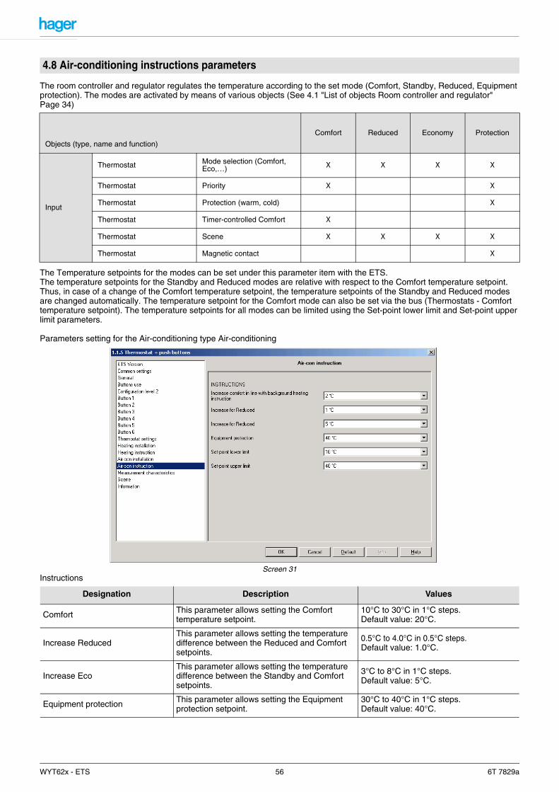
The room controller and regulator regulates the temperature according to the set mode (Comfort, Standby, Reduced, Equipment protection). The modes are activated by means of various objects (See 4.1 "List of objects Room controller and regulator" Page 34)
The Temperature setpoints for the modes can be set under this parameter item with the ETS. The temperature setpoints for the Standby and Reduced modes are relative with respect to the Comfort temperature setpoint. Thus, in case of a change of the Comfort temperature setpoint, the temperature setpoints of the Standby and Reduced modes are changed automatically. The temperature setpoint for the Comfort mode can also be set via the bus (Thermostats - Comfort temperature setpoint). The temperature setpoints for all modes can be limited using the Set-point lower limit and Set-point upper limit parameters.
Parameters setting for the Air-conditioning type Air-conditioning
Screen 31Instructions
4.8 Air-conditioning instructions parameters
Objects (type, name and function)
Comfort Reduced Economy Protection
Input
Thermostat Mode selection (Comfort, Eco,…) X X X X
Thermostat Priority X X
Thermostat Protection (warm, cold) X
Thermostat Timer-controlled Comfort X
Thermostat Scene X X X X
Thermostat Magnetic contact X
Designation Description Values
Comfort This parameter allows setting the Comfort temperature setpoint.
10°C to 30°C in 1°C steps.Default value: 20°C.
Increase ReducedThis parameter allows setting the temperature difference between the Reduced and Comfort setpoints.
0.5°C to 4.0°C in 0.5°C steps.Default value: 1.0°C.
Increase EcoThis parameter allows setting the temperature difference between the Standby and Comfort setpoints.
3°C to 8°C in 1°C steps.Default value: 5°C.
Equipment protection This parameter allows setting the Equipment protection setpoint.
30°C to 40°C in 1°C steps.Default value: 40°C.
WYT62x - ETS 56 6T 7829a

4.8.1 Parameters setting for the Air-conditioning type Heating and Air-conditioning
➜ Parameter Setting screen: See "Screen 31".
Instructions
Set-point lower limit This parameter allows setting a lower limit for the Comfort, Standby and Reduced setpoints.
10°C to 18°C in 1°C steps.Default value: 10°C.
Set-point upper limitThis parameter allows setting an upper limit for the Comfort, Standby and Reduced modes setpoints.
18°C to 40°C in 1°C steps.Default value: 40°C.
Designation Description Values
Increase comfort in line with background heating instruction
This parameter allows defining the minimum number of degrees the temperature must exceed the set Comfort temperature in order to activate the air-conditioning.(Example: Comfort temperature: 20°CIncrease for Comfort mode: 2°CIn Comfort mode, the regulator will start cooling at 22 °C).
1°C, 2°C, 3°C, 4°C, 5°C, 6°CDefault value: 2°C.
Increase Eco
This parameter allows setting the temperature difference with respect to the setpoint for the Standby mode.The setpoint of the Standby mode is higher, for the Air-conditioning function, than that of the Heating function, by the value set here.
0.5 °C to 0.4 °C in 0.5 °C steps.Default value: 1.0°C
Increase Reduced
This parameter allows setting the temperature difference with respect to the setpoint for the Reduced mode. The setpoint of the Standby mode is higher, for the Air-conditioning function, than that of the Heating function, by the value set here.
3 °C to 8 °C in 1 °C steps.Default value: 5°C
Equipment protection This parameter allows setting the temperature setpoint for Frost protection.
30 °C to 40 °C in 1 °C steps.Default value: 40°C
Set-point lower limit This parameter allows setting a lower limit for the Comfort, Standby and Reduced setpoints.
10 °C to 18 °C in 1 °C steps.Default value: 10°C
Set-point upper limit This parameter allows setting a lower limit for the Comfort, Standby and Reduced setpoints.
18 °C to 40 °C in 1 °C steps.Default value: 40°C
Designation Description Values
WYT62x - ETS 57 6T 7829a
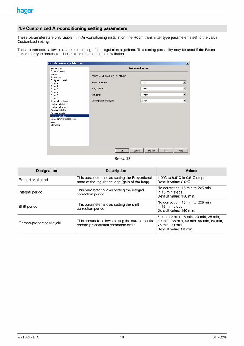
These parameters are only visible if, in Air-conditioning installation, the Room transmitter type parameter is set to the value Customized setting.
These parameters allow a customized setting of the regulation algorithm. This setting possibility may be used if the Room transmitter type parameter does not include the actual installation.
Screen 32
4.9 Customized Air-conditioning setting parameters
Designation Description Values
Proportional band This parameter allows setting the Proportional band of the regulation loop (gain of the loop).
1.0°C to 8.5°C in 0.5°C stepsDefault value: 2.0°C.
Integral period This parameter allows setting the integral correction period.
No correction, 15 min to 225 min in 15 min steps.Default value: 150 min.
Shift period This parameter allows setting the shift correction period.
No correction, 15 min to 225 min in 15 min steps.Default value: 150 min.
Chrono-proportional cycle This parameter allows setting the duration of the chrono-proportional command cycle.
5 min, 10 min, 15 min, 20 min, 25 min, 30 min, 35 min, 40 min, 45 min, 60 min, 75 min, 90 min.Default value: 20 min.
WYT62x - ETS 58 6T 7829a
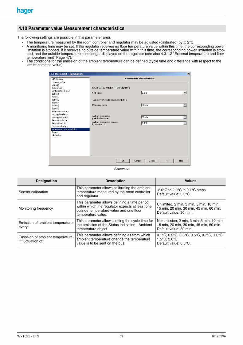
The following settings are possible in this parameter area.- The temperature measured by the room controller and regulator may be adjusted (calibrated) by ± 2°C.- A monitoring time may be set. If the regulator receives no floor temperature value within this time, the corresponding power
limitation is stopped. If it receives no outside temperature value within this time, the corresponding power limitation is stop-ped, and the outside temperature is no longer displayed on the regulator (see also 4.3.1.2 "External temperature and floor temperature limit" Page 47).
- The conditions for the emission of the ambient temperature can be defined (cycle time and difference with respect to the last transmitted value).
Screen 33
4.10 Parameter value Measurement characteristics
Designation Description Values
Sensor calibrationThis parameter allows calibrating the ambient temperature measured by the room controller and regulator.
-2.0°C to 2.0°C in 0.1°C steps.Default value: 0.0°C.
Monitoring frequency
This parameter allows defining a time period within which the regulator expects at least one outside temperature value and one floor temperature value.
Unlimited, 2 min, 3 min, 5 min, 10 min, 15 min, 20 min, 30 min, 45 min, 60 min.Default value: 30 min.
Emission of ambient temperature every:
This parameter allows setting the cycle time for the emission of the Status indication - Ambient temperature object.
No emission, 2 min, 3 min, 5 min, 10 min, 15 min, 20 min, 30 min, 45 min, 60 min.Default value: 30 min.
Emission of ambient temperature if fluctuation of:
This parameter allows defining as from which ambient temperature change the temperature value is to be sent on the bus.
0.1°C, 0.2°C, 0.3°C, 0.5°C, 0.7°C, 1.0°C, 1.5°C, 2.0°C.Default value: 0.5°C.
WYT62x - ETS 59 6T 7829a
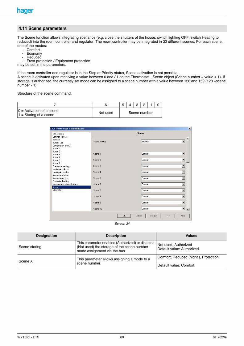
The Scene function allows integrating scenarios (e.g. close the shutters of the house, switch lighting OFF, switch Heating to reduced) into the room controller and regulator. The room controller may be integrated in 32 different scenes. For each scene, one of the modes:
- Comfort- Economy- Reduced- Frost protection / Equipment protection
may be set in the parameters.
If the room controller and regulator is in the Stop or Priority status, Scene activation is not possible. A scene is activated upon receiving a value between 0 and 31 on the Thermostat - Scene object (Scene number = value + 1). If storage is authorized, the currently set mode can be assigned to a scene number with a value between 128 and 159 (128 +scene number - 1).
Structure of the scene command:
Screen 34
4.11 Scene parameters
7 6 5 4 3 2 1 0
0 = Activation of a scene1 = Storing of a scene Not used Scene number
Designation Description Values
Scene storingThis parameter enables (Authorized) or disables (Not used) the storage of the scene number - mode assignment via the bus.
Not used, AuthorizedDefault value: Authorized.
Scene X This parameter allows assigning a mode to a scene number.
Comfort, Reduced (night ), Protection.
Default value: Comfort.
WYT62x - ETS 60 6T 7829a
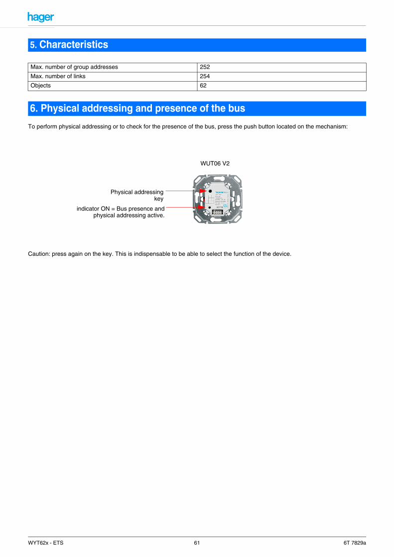
To perform physical addressing or to check for the presence of the bus, press the push button located on the mechanism:
Caution: press again on the key. This is indispensable to be able to select the function of the device.
5. Characteristics
Max. number of group addresses 252
Max. number of links 254
Objects 62
6. Physical addressing and presence of the bus
Physical addressingkey
indicator ON = Bus presence andphysical addressing active.
WUT06 V2
WYT62x - ETS 61 6T 7829a

WYT62x - ETS 62 6T 7829a