technical committee on electronic safety equipment … · technical committee on electronic safety...
TRANSCRIPT
TECHNICAL COMMITTEE ON ELECTRONIC SAFETY EQUIPMENT
Wyndham San Diego Bayside 1335 N. Harbor Drive San Diego, CA 92101
NFPA 1982 Second Draft Meeting
December 6-8, 2016
AGENDA
Meeting Start Time - 9:00 a.m. Local Time
Conference Call Line: 855-747-8824 Passcode: 902034
1. Call to order and Chair remarks – Bob Athanas, Chair
2. Self-introduction of members and guests
3. NFPA Staff Liaison Report – Dave Trebisacci
a. TC actions on Public Comments b. How to create Second Revisions c. Next revision cycle (PPE documents reorganization)
4. Approval of Minutes of July 12-14, 2016 Indianapolis meeting (attached)
5. NFPA 1982 Task Group report update
6. Review of Public Comments to NFPA 1982 (attached)

7. NFPA 1802 Task Group Reports (latest draft attached)
a. Chapter 1 - Administration TG – Jose Velo b. Chapter 2 - Referenced Publications TG – J. Velo c. Chapter 3 - Definitions TG – Tim Wolf, Matt Bowyer d. Chapter 4 - Certification – Gordon Sletmoe, Jim Rose, Steve Weinstein e. Chapter 5 - Product Labeling Information – Gerry Tarver, S. Weinstein, Craig
Gestler f. Chapter 6 - Design Requirements – Mike McKenna, Mike Worrell g. Chapter 7 - Performance Requirements – M. McKenna, M. Worrell, Steve
Townsend h. Chapter 8 - Test Methods – John Morris, Christina Spoons
8. Old business
9. New business – 2017 meeting dates (bring your calendars)
10. Adjourn at 5:00 p.m. Local Time, December 8, 2016

Page 1 of 4
MINUTES OF THE MEETING
TECHNICAL COMMITTEE ON ELECTRONIC SAFETY EQUIPMENT
12-14 JULY 2016 INDIANAPOLIS, IN
AGENDA ITEMS 1-2; CALL TO ORDER, SELF-INTRODUCTION OF MEMBERS AND GUESTS Chairman Athanas called the Committee to order at 09:12 on 12 July 2016. Chairman Athanas welcomed Committee members and guests and asked them to introduce themselves. AGENDA ITEM 3; APPROVAL OF MINUTES OF 10-12 MARCH 2016 MEETING, DALLAS (TX)
MOTION BY BRIAN MARTENS; SECOND BY TIM REHAK To approve the Minutes of the 10-12 March 2016 meeting in Dallas, TX
MOTION CARRIED.
AGENDA ITEM 4; NFPA STAFF LIAISON REPORT Staff Liaison David Trebisacci provided the staff liaison report and asked attendees to sign in on the appropriate Member or Guest sign-in sheet. He reviewed the following: an overview of the TC composition and balance, the timetable for the revisions of NFPA 1801 and NFPA 1982, the Second Revision and Balloting processes, and legal issues and restrictions with which the TC must comply. Members and Alternates Present:
Robert Athanas, Chairman FDNY/SAFE-IR Inc. Steven H. Weinstein, Acting Secretary Honeywell Safety Products David Trebisacci, Staff Liaison NFPA Kamil Agi K&A Wireless Joel Berger JVC Kenwood USA Corporation Todd Bianchi District of Columbia Fire & EMS Matt Bowyer NIOSH Louis Chavez Underwriters Laboratories Inc. (via telephone) Michelle Donnelly NIST John Facella Panther Pines Consulting, LLC William Forsyth USDA Forest Service Craig Gestler MSA
Page 2 of 4
Members and Alternates Present (continued): Wayne Haase Summit Safety, Inc. Simon Hogg Draeger Safety Michael Hussey Jackson County Fire District 3 Paul Kelly Underwriters Laboratories, Inc. (via telephone) Santiago Lasa Boston Fire Department Kevin Lentz Grace Industries, Inc. David Little David Little Steven Makky APCO International Inc. Brian Martens Harris Corporation John Morris Scott Safety Timothy Rehak NIOSH Kevin Roche Phoenix Fire Department James Rose SEI Matthew Shannon Scott Safety Gerry Tarver Tulsa Fire Department Greg Vrablik Honeywell Safety Products Mike Worrell FirstNet
Guests Present: Jeffrey Cook Houston Fire Department Chuck Jaris Motorola Solutions Joel Johnson Savox Pat Keelan E.F. Johnson Technologies Barry Leitch FirstNet Clint Mayhue Avon Protection Jason N. Messerschmidt Flir Systems Judge Morgan III Scott Safety Joe Namm Motorola Solutions Jacob Norrby Interspiro John Rehayem Otto Engineering Karl Rydqvist Flir Systems Christopher Sampl Fairfax County Fire Rescue Matt Taylor Avon Protection Rob Tieman Bullard Jon Turner Avon Protection Kevin Wolf Intertek
AGENDA ITEM 5; CHAIRMAN’S REMARKS Chairman Athanas commended the TC for its high voting response rate for NFPA 1982 balloting. He mentioned that in the December 2016 meeting in San Diego, the TC would be asked to include both primary and alternate meeting dates for 2017.

Page 3 of 4
AGENDA ITEM 6; NFPA 1982 PASS SOUND TASK GROUP REPORT AND REVIEW OF RECOMMENDATIONS FOR PROPOSED CHANGE Craig Gestler, Chairman of the PASS Sound Task Group, presented a report on the work the Task Group has done to develop a new standardized PASS sound. His presentation covered the history of the issue and the testing work recently done at Intertek and NIST to validate the proposed 2018 PASS sound. The recommendation of the Task Group is to continue to move forward with the sound proposed in the First Revision of NFPA 1982. The SCBA manufacturers (Scott, MSA, Honeywell, Avon, Dräger and Interspiro) then demonstrated their PASS devices three different ways:
(1) A 2013 PASS sound set at the current 2013 minimum requirement of 95 dBA peak response at 3 meters
(2) A 2018 PASS sound “detuned” to the proposed 2018 minimum requirement of 92 dBA fast response at 1 meter
(3) A 2018 PASS sound representing a normal 2018 production unit AGENDA ITEM 7; REVIEW OF PUBLIC COMMENTS FOR NFPA 1801 The TC reviewed and acted upon Public Comments submitted for NFPA 1801. The TC created Second Revisions based on those actions and additional committee actions. AGENDA ITEM 8; NFPA 1802 DRAFT DEVELOPMENT The TC continued its review and revision of NFPA 1802. Chairman Athanas directed Mike McKenna, Chairman of the Task Group on Chapter 6, to have a solution for a universal connector, taking into account intrinsic safety, by September 15. Chairman Athanas asked the TC members to communicate with Chairman McKenna regarding any issues or suggestions by that date. Chairman Athanas directed Steve Townsend, Chairman of the HazLoc Task Group, to have a solution for intrinsic safety developed by September 15. This could include requiring Division 2 certification instead of Division 1. Chairman Athanas asked the TC members to communicate with Chairman Townsend regarding any issues or suggestions by that date. It is up to the Task Group Chairmen to ensure that all appropriate TC members participate in the development of solutions, even if they are not currently members of the Task Groups. AGENDA ITEM 9; OLD BUSINESS Acting Secretary Steve Weinstein reminded all Task Group Chairmen that Task Group meetings should occur on a scheduled basis in between Technical Committee meetings. The Technical Committee is not responsible for performing a Task Group’s discussion and editing function at a full TC meeting. The Task Group should present at a TC meeting what is intended to be a final version of the sections of the standard that fall within their jurisdiction. This includes content, NFPA standard language, grammar and punctuation. The TC should be able to review the Task Group’s work and determine whether it is acceptable, or whether it needs to

Page 4 of 4
be further revised. Such revision may be accomplished at the TC meeting, or it may need to be done through additional, subsequent meetings of the Task Group. A Task Group Chairman attending a TC meeting with no work having been undertaken since the last TC meeting, under the assumption that the TC will perform that work, is not acceptable. AGENDA ITEM 10; NEW BUSINESS Chairman Athanas reminded the TC that the next meeting will be held on December 6-8 in San Diego, CA. AGENDA ITEM 11; ADJOURNMENT
MOTION BY MIKE HUSSEY; SECOND BY BRIAN MARTENS To adjourn.
MOTION CARRIED.
Chairman Athanas adjourned the meeting at 13:15 on 14 July 2016. Respectfully submitted, Steven H. Weinstein, Acting Secretary Technical Committee on Electronic Safety Equipment

Public Comment No. 3-NFPA 1982-2016 [ Section No. 4.1.8 ]
4.1.8
The certification organization shall not permit any manufacturer to label any PASS as compliant with the2013 edition of this standard on or after August 31, 2018 12 months from the effective date of this revisionof the standard .
Statement of Problem and Substantiation for Public Comment
TC agreed to make the period 12 months to align with other standards and to avoid the multiple TIAs as experienced with the 2013 revision.
Related Item
First Revision No. 2-NFPA 1982-2016 [Section No. 4.1.8]
Submitter Information Verification
Submitter Full Name: Simon Hogg
Organization: Draeger Safety UK Ltd.
Street Address:
City:
State:
Zip:
Submittal Date: Tue Oct 25 16:38:44 EDT 2016
National Fire Protection Association Report http://submittals.nfpa.org/TerraViewWeb/ContentFetcher?commentPara...
1 of 13 11/18/2016 9:37 AM
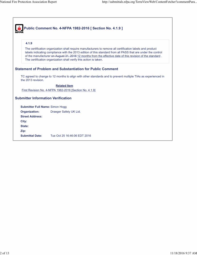
Public Comment No. 4-NFPA 1982-2016 [ Section No. 4.1.9 ]
4.1.9
The certification organization shall require manufacturers to remove all certification labels and productlabels indicating compliance with the 2013 edition of this standard from all PASS that are under the controlof the manufacturer on August 31, 2018 12 months from the effective date of this revision of the standard .The certification organization shall verify this action is taken.
Statement of Problem and Substantiation for Public Comment
TC agreed to change to 12 months to align with other standards and to prevent multiple TIAs as experienced in the 2013 revision.
Related Item
First Revision No. 4-NFPA 1982-2016 [Section No. 4.1.9]
Submitter Information Verification
Submitter Full Name: Simon Hogg
Organization: Draeger Safety UK Ltd.
Street Address:
City:
State:
Zip:
Submittal Date: Tue Oct 25 16:46:06 EDT 2016
National Fire Protection Association Report http://submittals.nfpa.org/TerraViewWeb/ContentFetcher?commentPara...
2 of 13 11/18/2016 9:37 AM

Public Comment No. 15-NFPA 1982-2016 [ Section No. 5.1.8 ]
5.1.8
PASS also shall be labeled as certified at least to the requirements for Class I, Groups C and D; andClass II, Groups E, F, and G; Division 1 hazardous locations specified in ANSI/UL 913, Standard forIntrinsically Safe Apparatus and Associated Apparatus for Use in Class I, II, and III, Division 1 Hazardous(Classified) Locations. Where an acceptable alterna ve hazardous loca ons Intrinsic Safety standard has been used, the alterna ve
hazardous loca ons marking shall be shown clearly on the product approval label as specified by the agency
performing the tests.
Statement of Problem and Substantiation for Public Comment
Opens the use of later or equivalent intrinsic safety standards.
For this standard, UL913 ed. 6 has been confirmed to provide sufficient protection for the application. This edition has been superseded by edition 7th and later 8th editions which are equivalent to the IEC60079/EN60079 series of standards.To open the approval path of PASS to NFPA1982 to secure alternative routes and in support of continuous improvements in product developments, extra wording is required in the 2018 revision to allow the approval agency to follow in an open manner.The current wording requires the testing and certification to the 6th edition of UL913 however there is no acceptable clause to permit the manufacturer to receive approval to at least the same minimum locations by using the later editions of the same standard or to the IECEx/EN 60079 series of standards which are equivalent to the later editions of UL913 calling up the UL equivalent of the IEC60079 series of standards.It is reasonable to permit the certification to later or equivalent intrinsic safety standards and not have to also receive certification to the 6th edition.
Related Public Comments for This Document
Related Comment Relationship
Public Comment No. 16-NFPA 1982-2016 [Section No. 7.6]
Related Item
First Revision No. 36-NFPA 1982-2016 [Section No. 7.6]
Submitter Information Verification
Submitter Full Name: Simon Hogg
Organization: Draeger Safety UK Ltd.
Street Address:
City:
State:
Zip:
Submittal Date: Tue Nov 15 14:08:16 EST 2016
National Fire Protection Association Report http://submittals.nfpa.org/TerraViewWeb/ContentFetcher?commentPara...
3 of 13 11/18/2016 9:37 AM
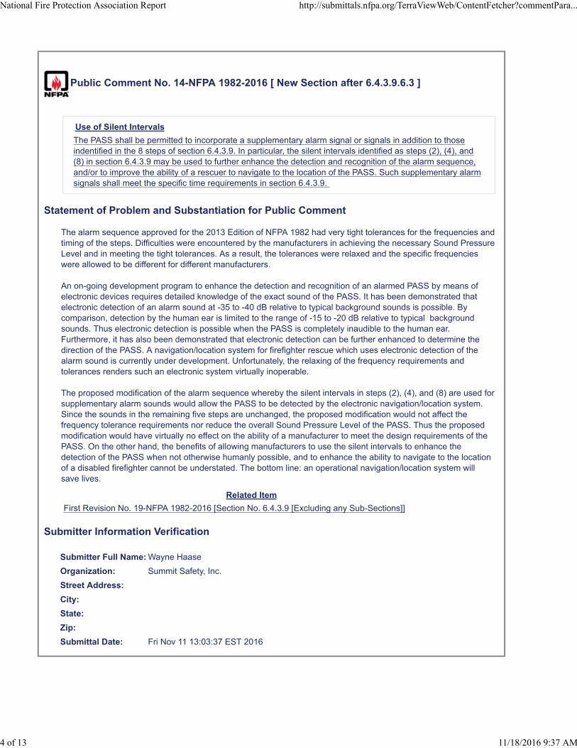
Public Comment No. 14-NFPA 1982-2016 [ New Section after 6.4.3.9.6.3 ]
Use of Silent Intervals
The PASS shall be permitted to incorporate a supplementary alarm signal or signals in addition to thoseindentified in the 8 steps of section 6.4.3.9. In particular, the silent intervals identified as steps (2), (4), and(8) in section 6.4.3.9 may be used to further enhance the detection and recognition of the alarm sequence,and/or to improve the ability of a rescuer to navigate to the location of the PASS. Such supplementary alarmsignals shall meet the specific time requirements in section 6.4.3.9.
Statement of Problem and Substantiation for Public Comment
The alarm sequence approved for the 2013 Edition of NFPA 1982 had very tight tolerances for the frequencies and timing of the steps. Difficulties were encountered by the manufacturers in achieving the necessary Sound Pressure Level and in meeting the tight tolerances. As a result, the tolerances were relaxed and the specific frequencies were allowed to be different for different manufacturers.
An on-going development program to enhance the detection and recognition of an alarmed PASS by means of electronic devices requires detailed knowledge of the exact sound of the PASS. It has been demonstrated that electronic detection of an alarm sound at -35 to -40 dB relative to typical background sounds is possible. By comparison, detection by the human ear is limited to the range of -15 to -20 dB relative to typical background sounds. Thus electronic detection is possible when the PASS is completely inaudible to the human ear. Furthermore, it has also been demonstrated that electronic detection can be further enhanced to determine the direction of the PASS. A navigation/location system for firefighter rescue which uses electronic detection of the alarm sound is currently under development. Unfortunately, the relaxing of the frequency requirements and tolerances renders such an electronic system virtually inoperable.
The proposed modification of the alarm sequence whereby the silent intervals in steps (2), (4), and (8) are used for supplementary alarm sounds would allow the PASS to be detected by the electronic navigation/location system. Since the sounds in the remaining five steps are unchanged, the proposed modification would not affect the frequency tolerance requirements nor reduce the overall Sound Pressure Level of the PASS. Thus the proposed modification would have virtually no effect on the ability of a manufacturer to meet the design requirements of the PASS. On the other hand, the benefits of allowing manufacturers to use the silent intervals to enhance the detection of the PASS when not otherwise humanly possible, and to enhance the ability to navigate to the location of a disabled firefighter cannot be understated. The bottom line: an operational navigation/location system will save lives.
Related Item
First Revision No. 19-NFPA 1982-2016 [Section No. 6.4.3.9 [Excluding any Sub-Sections]]
Submitter Information Verification
Submitter Full Name: Wayne Haase
Organization: Summit Safety, Inc.
Street Address:
City:
State:
Zip:
Submittal Date: Fri Nov 11 13:03:37 EST 2016
National Fire Protection Association Report http://submittals.nfpa.org/TerraViewWeb/ContentFetcher?commentPara...
4 of 13 11/18/2016 9:37 AM

Public Comment No. 5-NFPA 1982-2016 [ Section No. 6.4.4 ]
6.4.4 Low Power Source Warning Signal.
6.4.4.1
While in the sensing mode, PASS shall emit a recurrent audible low power source warning signal when thepower source voltage or power source percent capacity remaining is depleted to the level that will maintainthe alarm signal level of at least 95 dBA for at least at a minimum of 92 dBA for a minimum of 1 hour.
6.4.4.2
The power source shall be discharged at a rate that is equal to the average current draw, ±10 percent of thesame model PASS, while in the alarm mode. The rate shall be determined by measurement by thecertification organization.
6.4.4.3
The low power source warning signal sound shall be distinct and different from the pre-alarm signal(s) andthe alarm signal.
6.4.4.4
The low power source warning signal shall have an interval of not greater than 30 seconds.
6.4.4.5
While in the off mode and with the power source voltage or power source percent remaining at or belowthe level specified in 6.4.4.1, the system that causes the activation of the low power source warning signalshall cancel the operational signal so that it shall not sound when the PASS is switched to the sensingmode.
Statement of Problem and Substantiation for Public Comment
With the introduction of rechargeable batteries to the SCBA/PASS alarms, it has become very difficult to determine the low battery point by only measuring the battery voltage. Alkaline batteries have a linear, sloping discharge curve and the remaining battery capacity can be determined from the measured voltage. Rechargeable cells, however, have a very flat voltage discharge curve and it is nearly impossible to accurately determine remaining capacity from the voltage measurement. Most rechargeable batteries are used in conjunction with "gas gauge" chips which accurately measure the charge moving in and out of the cell and make an accurate assessment of the remaining battery capacity.
Related Public Comments for This Document
Related Comment Relationship
Public Comment No. 6-NFPA 1982-2016 [Section No. 8.2.8.3]
Related Item
First Revision No. 49-NFPA 1982-2016 [Section No. 8.2.8.1]
Submitter Information Verification
Submitter Full Name: Craig Gestler
Organization: MSA ]
Affilliation: MSA
Street Address:
City:
State:
Zip:
National Fire Protection Association Report http://submittals.nfpa.org/TerraViewWeb/ContentFetcher?commentPara...
5 of 13 11/18/2016 9:37 AM

Submittal Date: Thu Oct 27 16:04:51 EDT 2016
National Fire Protection Association Report http://submittals.nfpa.org/TerraViewWeb/ContentFetcher?commentPara...
6 of 13 11/18/2016 9:37 AM
Public Comment No. 9-NFPA 1982-2016 [ Section No. 7.1.1.1 ]
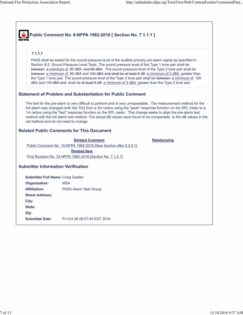
7.1.1.1
PASS shall be tested for the sound pressure level of the audible primary pre-alarm signal as specified inSection 8.2, Sound Pressure Level Tests. The sound pressure level of the Type 1 tone pair shall bebetween a minimum of 80 dBA and 95 dBA . The sound pressure level of the Type 2 tone pair shall bebetween a minimum of 86 dBA and 104 dBA and shall be at least 6 dB a minimum of 3 dBA greater thanthe Type 1 tone pair. The sound pressure level of the Type 3 tone pair shall be between a minimum of 100dBA and 110 dBA and shall be at least 6 dB a minimum of 3 dBA greater than the Type 2 tone pair.
Statement of Problem and Substantiation for Public Comment
The test for the pre-alarm is very difficult to perform and is very unrepeatable. The measurement method for the full alarm was changed (with the TIA) from a 3m radius using the "peak" response function on the SPL meter to a 1m radius using the "fast" response function on the SPL meter. This change seeks to align the pre-alarm test method with the full alarm test method. The actual dB values were found to be comparable to the dB values in the old method and do not need to change.
Related Public Comments for This Document
Related Comment Relationship
Public Comment No. 10-NFPA 1982-2016 [New Section after 8.2.9.1]
Related Item
First Revision No. 33-NFPA 1982-2016 [Section No. 7.1.2.1]
Submitter Information Verification
Submitter Full Name: Craig Gestler
Organization: MSA
Affilliation: PASS Alarm Task Group
Street Address:
City:
State:
Zip:
Submittal Date: Fri Oct 28 08:07:45 EDT 2016
National Fire Protection Association Report http://submittals.nfpa.org/TerraViewWeb/ContentFetcher?commentPara...
7 of 13 11/18/2016 9:37 AM

Public Comment No. 16-NFPA 1982-2016 [ Section No. 7.6 ]
7.6 Intrinsic Safety.
PASS shall be certified for intrinsic safety as specified in ANSI/UL 913, Standard for Intrinsically SafeApparatus and Associated Apparatus for Use in Class I, II, and III, Division 1 Hazardous (Classified)Locations, and shall as a minimum, meet the requirements for Class I, Groups C and D, and Class II,Groups E, F, and G, Division 1 hazardous locations. It is permi ed to use an alterna ve Intrinsic Safety
standard provided that at least the minimum protec on level specified here for gas and dust groups is achieved.
A higher level of Intrinsic Safety is also acceptable whether using the standard specified here or an acceptable
equivalent. Any alterna ves to be used shall be agreed with the cer fica on organisa on. See sec on 5.1.8 for
addi onal labelling requirements.
Statement of Problem and Substantiation for Public Comment
To allow use of alternative intrinsic safety standards
For this standard, UL913 ed. 6 has been confirmed to provide sufficient protection for the application. This edition has been superseded by edition 7th and later 8th editions which are equivalent to the IEC60079/EN60079 series of standards.To open the approval path of PASS to NFPA1982 to secure alternative routes and in support of continuous improvements in product developments, extra wording is required in the 2018 revision to allow the approval agency to follow in an open manner.The current wording requires the testing and certification to the 6th edition of UL913 however there is no acceptable clause to permit the manufacturer to receive approval to at least the same minimum locations by using the later editions of the same standard or to the IECEx/EN 60079 series of standards which are equivalent to the later editions of UL913 calling up the UL equivalent of the IEC60079 series of standards.
Related Public Comments for This Document
Related Comment Relationship
Public Comment No. 15-NFPA 1982-2016 [Section No. 5.1.8] Label marking requirements
Public Comment No. 17-NFPA 1982-2016 [New Section after A.7.1.1.2]
Related Item
First Revision No. 36-NFPA 1982-2016 [Section No. 7.6]
Submitter Information Verification
Submitter Full Name: Simon Hogg
Organization: Draeger Safety UK Ltd.
Street Address:
City:
State:
Zip:
Submittal Date: Tue Nov 15 14:19:44 EST 2016
National Fire Protection Association Report http://submittals.nfpa.org/TerraViewWeb/ContentFetcher?commentPara...
8 of 13 11/18/2016 9:37 AM

Public Comment No. 6-NFPA 1982-2016 [ Section No. 8.2.8.3 ]
8.2.8.3
Before starting the test, the specimen’s power source voltage shall be discharged to the voltage level orpercent capacity remaining value at which the PASS first emits the low power source warning signalspecified in 6.4.4.
Statement of Problem and Substantiation for Public Comment
This ties to public comment Number 6. Specifying that the battery must be discharged to the low battery trip point voltage OR the low battery trip point capacity remaining percentage.
Related Public Comments for This Document
Related Comment Relationship
Public Comment No. 5-NFPA 1982-2016 [Section No. 6.4.4]
Related Item
First Revision No. 49-NFPA 1982-2016 [Section No. 8.2.8.1]
Submitter Information Verification
Submitter Full Name: Craig Gestler
Organization: MSA
Affilliation: MSA
Street Address:
City:
State:
Zip:
Submittal Date: Thu Oct 27 16:34:35 EDT 2016
National Fire Protection Association Report http://submittals.nfpa.org/TerraViewWeb/ContentFetcher?commentPara...
9 of 13 11/18/2016 9:37 AM

Public Comment No. 10-NFPA 1982-2016 [ New Section after 8.2.9.1 ]
TITLE OF NEW CONTENT
The sound pressure level for the alarm signal shall be measured in a spherical radius at a a distance of 1 m2.5/-0 cm (3.3 ft 1/-0 in) from the specimen's annunciator.
Statement of Problem and Substantiation for Public Comment
The test for the pre-alarm is very difficult to perform and is very unrepeatable. The measurement method for the full alarm was changed (with the TIA) from a 3m radius using the "peak" response function on the SPL meter to a 1m radius using the "fast" response function on the SPL meter. This change seeks to align the pre-alarm test method with the full alarm test method.
Related Public Comments for This Document
Related Comment Relationship
Public Comment No. 9-NFPA 1982-2016 [Section No. 7.1.1.1]
Related Item
First Revision No. 33-NFPA 1982-2016 [Section No. 7.1.2.1]
Submitter Information Verification
Submitter Full Name: Craig Gestler
Organization: MSA
Affilliation: PASS Alarm TG
Street Address:
City:
State:
Zip:
Submittal Date: Fri Oct 28 08:28:24 EDT 2016
National Fire Protection Association Report http://submittals.nfpa.org/TerraViewWeb/ContentFetcher?commentPara...
10 of 13 11/18/2016 9:37 AM
Public Comment No. 7-NFPA 1982-2016 [ Section No. 8.2.9.2 ]
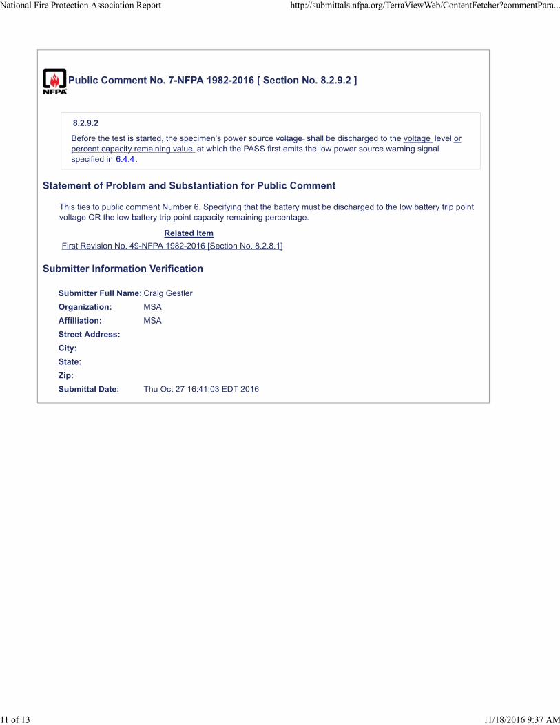
8.2.9.2
Before the test is started, the specimen’s power source voltage shall be discharged to the voltage level orpercent capacity remaining value at which the PASS first emits the low power source warning signalspecified in 6.4.4.
Statement of Problem and Substantiation for Public Comment
This ties to public comment Number 6. Specifying that the battery must be discharged to the low battery trip point voltage OR the low battery trip point capacity remaining percentage.
Related Item
First Revision No. 49-NFPA 1982-2016 [Section No. 8.2.8.1]
Submitter Information Verification
Submitter Full Name: Craig Gestler
Organization: MSA
Affilliation: MSA
Street Address:
City:
State:
Zip:
Submittal Date: Thu Oct 27 16:41:03 EDT 2016
National Fire Protection Association Report http://submittals.nfpa.org/TerraViewWeb/ContentFetcher?commentPara...
11 of 13 11/18/2016 9:37 AM
Public Comment No. 8-NFPA 1982-2016 [ Section No. 8.2.10.2 ]
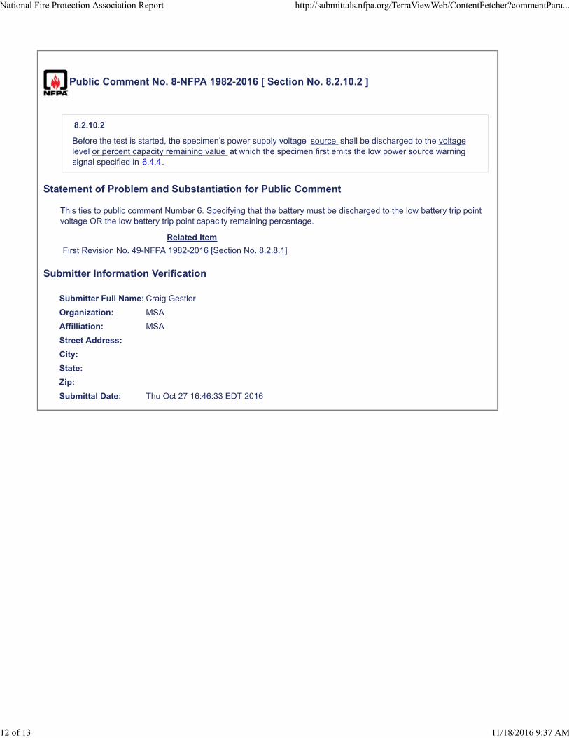
8.2.10.2
Before the test is started, the specimen’s power supply voltage source shall be discharged to the voltagelevel or percent capacity remaining value at which the specimen first emits the low power source warningsignal specified in 6.4.4.
Statement of Problem and Substantiation for Public Comment
This ties to public comment Number 6. Specifying that the battery must be discharged to the low battery trip point voltage OR the low battery trip point capacity remaining percentage.
Related Item
First Revision No. 49-NFPA 1982-2016 [Section No. 8.2.8.1]
Submitter Information Verification
Submitter Full Name: Craig Gestler
Organization: MSA
Affilliation: MSA
Street Address:
City:
State:
Zip:
Submittal Date: Thu Oct 27 16:46:33 EDT 2016
National Fire Protection Association Report http://submittals.nfpa.org/TerraViewWeb/ContentFetcher?commentPara...
12 of 13 11/18/2016 9:37 AM
Public Comment No. 17-NFPA 1982-2016 [ New Section after A.7.1.1.2 ]
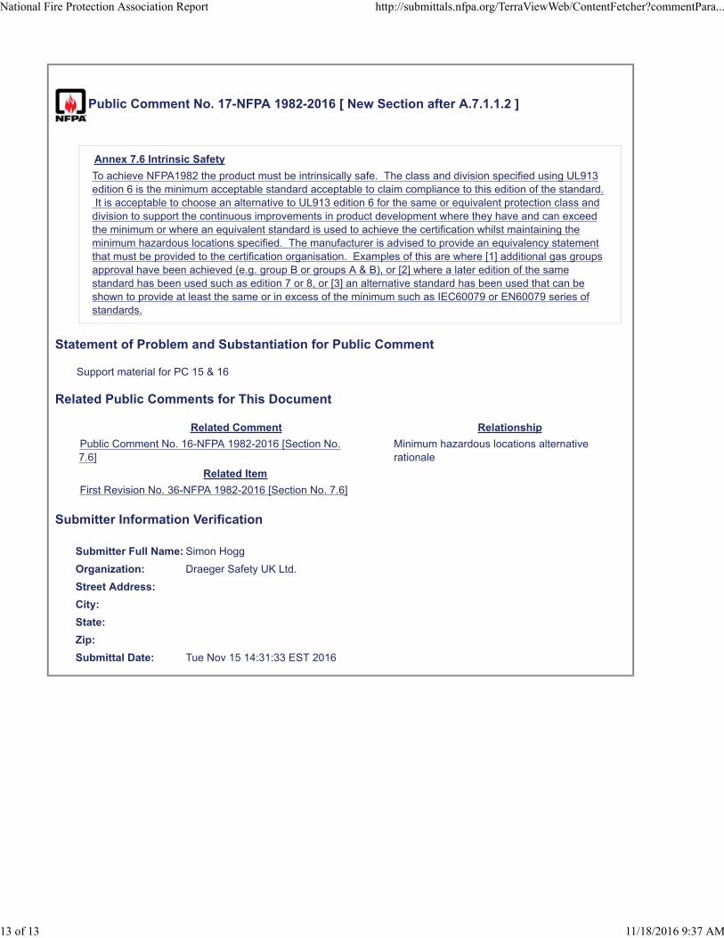
Annex 7.6 Intrinsic Safety
To achieve NFPA1982 the product must be intrinsically safe. The class and division specified using UL913edition 6 is the minimum acceptable standard acceptable to claim compliance to this edition of the standard. It is acceptable to choose an alternative to UL913 edition 6 for the same or equivalent protection class anddivision to support the continuous improvements in product development where they have and can exceedthe minimum or where an equivalent standard is used to achieve the certification whilst maintaining theminimum hazardous locations specified. The manufacturer is advised to provide an equivalency statementthat must be provided to the certification organisation. Examples of this are where [1] additional gas groupsapproval have been achieved (e.g. group B or groups A & B), or [2] where a later edition of the samestandard has been used such as edition 7 or 8, or [3] an alternative standard has been used that can beshown to provide at least the same or in excess of the minimum such as IEC60079 or EN60079 series ofstandards.
Statement of Problem and Substantiation for Public Comment
Support material for PC 15 & 16
Related Public Comments for This Document
Related Comment Relationship
Public Comment No. 16-NFPA 1982-2016 [Section No.7.6]
Minimum hazardous locations alternativerationale
Related Item
First Revision No. 36-NFPA 1982-2016 [Section No. 7.6]
Submitter Information Verification
Submitter Full Name: Simon Hogg
Organization: Draeger Safety UK Ltd.
Street Address:
City:
State:
Zip:
Submittal Date: Tue Nov 15 14:31:33 EST 2016
National Fire Protection Association Report http://submittals.nfpa.org/TerraViewWeb/ContentFetcher?commentPara...
13 of 13 11/18/2016 9:37 AM
1
REV. 11/17/2016
***IMPORTANT: THIS DRAFT IS FOR TASK GROUP OR TECHNICAL COMMITTEE REVIEW ONLY AND HAS NOT YET ENTERED A REVISION CYCLE AND PROCESSED ACCORDING TO
THE REGULATIONS GOVERNING THE DEVELOPMENT OF NFPA STANDARDS***
NFPA 1802
Standard on Two‐Way, Portable RF Voice Communications Devices for Use by Emergency
Services Personnel in the Hazard Zone
20XX Edition
Chapter 1 Administration
1.1 Scope. This standard shall identify the operating environment parameters, as well as the minimum requirements for the design, performance, testing, and certification of two‐way, portable RF voice communications devices for use by emergency services personnel within the hazard zone during emergency incident operations without compromising compatibility with field emergency services communications networks. 1.1.1 This standard shall specify requirements for two‐way, portable RF voice communications devices for use by emergency services personnel. 1.1.2 Reserved. 1.1.3 Except where referenced by this standard, requirements for two‐way, portable RF voice communications devices of other standards shall not apply. 1.1.4 Any accessories or enhancements built into, attached to, or sold with the two‐way, portable RF voice communications device by the manufacturer for later attachment shall be tested with the two‐way, portable voice communications device with those accessories and enhancements installed or attached, as specified in Table 4.3.9, to ensure the performance and functions of the two‐way, portable RF voice communications device. 1.1.5 This standard shall not be construed as addressing all of the safety concerns, if any, associated with the use of this standard by testing facilities. It shall be the responsibility of the persons and organizations that use this standard to establish safety

2
REV. 11/17/2016
and health practices and to determine the applicability of regulatory limitations prior to use of this standard for designing, manufacturing, and testing. 1.1.6 Nothing herein shall restrict any jurisdiction or manufacturer from exceeding these minimum requirements. 1.2 Purpose.
1.2.1 The purpose of this standard shall be to establish minimum requirements for two‐way, portable RF voice communications devices. 1.2.2 Controlled laboratory tests used to determine compliance with the performance requirements of this standard shall not be deemed as establishing performance levels for all situations, environments, and conditions to which two‐way, portable RF voice communications devices could be exposed. 1.2.3 This standard shall not be interpreted or used as a detailed manufacturing or purchase specification, but it shall be permitted to be referenced in purchase specifications as minimum requirements. 1.3 Application.
1.3.1 This standard shall apply to all two‐way, portable RF voice communications devices for use by emergency services personnel. 1.3.2 This standard shall apply to the design, performance, manufacturing, testing, and certification of new two‐way, portable RF voice communications devices for use by emergency services personnel. 1.3.3 This standard shall not apply to any two‐way, portable RF voice communications devices manufactured in accordance with other standards. However, manufacturers shall be permitted to have noncompliant two‐way, portable RF voice communications devices modified to meet the requirements of this standard and become certified as compliant with this standard. 1.3.4* This standard shall not apply to accessories and enhancements that could be built into or attached to a certified two‐way, portable RF voice communications device before or after purchase but that are not necessary for the device to meet the requirements of this standard. 1.3.5* Any accessories, enhancements or optional components built into, attached to, or sold with the two‐way, portable RF voice communications device by the manufacturer for later attachment for use in the hazard zone shall be attached to the

3
REV. 11/17/2016
device or a test substitute as specified in Section XX when the device is tested as specified in Table 4.3.9 to ensure the performance and functions of the device. 1.3.6 This standard shall not apply to criteria for use of two‐way, portable RF voice communications devices by emergency services personnel. 1.4 Units.
1.4.1 In this standard, values for measurement are followed by an equivalent in parentheses, but only the first stated value shall be regarded as the requirement. 1.4.2 Equivalent values in parentheses shall not be considered as the requirement because those values are approximate.
Chapter 2 Referenced Publications 2.1 General. The documents or portions thereof listed in this chapter are referenced within this standard and shall be considered part of the requirements of this document. 2.2 NFPA Publications. National Fire Protection Association, 1 Batterymarch Park, Quincy, MA 02169‐7471. NFPA 1221, Standard for the Installation, Maintenance, and Use of Emergency Services Communications systems, 2016 Edition. NFPA 1500, Standard on Fire Department Occupational Safety and Health Program, 2018 Edition. NFPA 1801, Standard on Thermal Imagers for the Fire Service, 2018 Edition. NFPA 1971, Standard on Protective Ensembles for Structural Fire Fighting and Proximity Fire Fighting, 2018 Edition. NFPA 1981, Standard on Open‐Circuit Self‐Contained Breathing Apparatus (SCBA) for Emergency Services, 2018. 2.3 Other Publications. 2.3.1 ANSI Publications. American National Standards Institute, Inc., 25 West 43rd Street, 4th Floor, New York, NY 10036.
4
REV. 11/17/2016
ANSI/ISA S1.13, Methods for Measurement of Sound Pressure Level, 2005. ANSI S3.2 2009 (R2014) Method for Measuring the Intelligibility of Speech over Communication Systems. 2.3.2 ASME Publications. American Society of Mechanical Engineers, 3 Park Avenue, New York, NY 10016. ASME B46.1, 2009, Surface Texture (Surface Roughness, Waviness, and Lay). 2.3.3 ASTM Publications. ASTM International, 100 Barr Harbor Drive, P.O. Box C700, West Conshohocken, PA 19428‐ 2959. ASTM B117, Standard Practice for Operating Salt Spray (Fog) Apparatus, 2011. ASTM D1003, Standard Test Method for Haze and Luminous Transmittance of Transparent Plastics, 2013. ASTM F903, Standard Test Method for Resistance of Materials Used in Protective Clothing to Penetration by Liquids, 2010. 2.3.4 Bluetooth. Bluetooth SIG, Inc. Headquarters, 5209 Lake Washington Blvd NE, Suite 350, Kirkland, WA 98033. Bluetooth Core Specification version 4.0. 2.3.5 IEEE Publications. Institute of Electrical and Electronics Engineers, 445 Hoes Lane, Piscataway, NJ 08854‐4141. IEEE 802.15.1‐2002, IEEE Standard for Telecommunications and Information Exchange Between Systems – LAN/MAN – Specific Requirements – Part 15: Wireless Medium Access Control (MAC) and Physical Layer (PHY) Specifications for Wireless Personal Area Networks (WPANs). 2.3.6 ISO/IEC Publications. International Organization for Standardization, ISO Central Secretariat, BIBC II, Chemin de Blandonnet 8, CP401, 1214 Vernier, Geneva, Switzerland. ISO Guide 27, Guidelines for corrective action to be taken by a certification body in the event of misuse of its mark of conformity, 1983. ISO 9001, Quality management systems — Requirements, 2008. ISO 9001, Quality management systems — Requirements, 2015.

5
REV. 11/17/2016
ISO/IEC 17011, Conformity assessment — General requirements for accreditation bodies accrediting conformity assessment bodies, 2004. ISO/IEC 17021‐1:2015, Conformity assessment — Requirements for bodies providing audit and certification of management systems. ISO/IEC 17025, General requirements for the competence of testing and calibration laboratories, 2005, Technical Corrigendum 1, 2006. ISO/IEC Guide 17065:2012 Conformity assessment — Requirements for bodies certifying products, processes and services. ISO 17493, Clothing and equipment for protection against heat — Test method for convective heat resistance using a hot air circulating oven, 2000. IEC 60529, Degrees of protection provided by enclosures (IP Code) 2nd Edition, 2015. 2.3.7 NIST Publications. National Institute of Standards and Technology, 100 Bureau Drive, Stop 1070, Gaithersburg, MD 20899‐1070. NIST Technical Note 1477, Testing of Portable Radios in the firefighting environment, August 2006. NIST Technical Note 1850, Performance of Portable Radios exposed to elevated temperatures, September 2014. 2.3.8 Telecommunications Industry Association (TIA). 1320 North Courthouse Road, Suite 200 Arlington, VA 22201. TIA 102.CAAA‐E, Project 25 Digital C4FM/CQPSK Transceiver Measurement Methods. TIA 603‐E, Land Mobile FM or PM Communications Equipment Measurement and Performance Standards. TIA 4950, Requirements for Battery‐Powered, Portable Land Mobile Radio Applications in Class I, II, and III, Division 1, Hazardous (Classified) Locations. 2.3.9 UL Publications. 2.3.10 U.S. Government Publications. U.S. Government Publishing Office, 732 North Capitol Street, NW, Washington, DC 20401‐0001. Title 42, Code of Federal Regulations, Part 84, Respiratory Protective Devices, Tests for Permissibility, 8 June 1995.

6
REV. 11/17/2016
2.3.10 Other Publications. Merriam‐Webster’s Collegiate Dictionary, 11th edition, Merriam‐Webster, Inc., Springfield, MA, 2003. 2.4 References for Extracts in Mandatory Sections. (Reserved) Chapter 3 Definitions
3.1 General. The definitions contained in this chapter shall apply to the terms used in this standard. Where terms are not defined in this chapter or within another chapter, they shall be defined using their ordinarily accepted meanings within the context in which they are used. Merriam‐Webster’s Collegiate Dictionary, 11th edition, shall be the source for the ordinarily accepted meaning. 3.2 NFPA Official Definitions. 3.2.1* Approved. Acceptable to the authority having jurisdiction. 3.2.2* Authority Having Jurisdiction (AHJ). An organization, office, or individual responsible for enforcing the requirements of a code or standard, or for approving equipment, materials, an installation, or a procedure. 3.2.3 Labeled. Equipment or materials to which has been attached a label, symbol, or other identifying mark of an organization that is acceptable to the authority having jurisdiction and concerned with product evaluation, that maintains periodic inspection of production of labeled equipment or materials, and by whose labeling the manufacturer indicates compliance with appropriate standards or performance in a specified manner. 3.2.4* Listed. Equipment, materials, or services included in a list published by an organization that is acceptable to the authority having jurisdiction and concerned with evaluation of products or services, that maintains periodic inspection of production of listed equipment or materials or periodic evaluation of services, and whose listing states that either the equipment, material, or service meets appropriate designated standards or has been tested and found suitable for a specified purpose. 3.2.5 Shall. Indicates a mandatory requirement. 3.2.6 Should. Indicates a recommendation or that which is advised but not required.
7
REV. 11/17/2016
3.2.7 Standard. A document, the main text of which contains only mandatory provisions using the word “shall” to indicate requirements and which is in a form generally suitable for mandatory reference by another standard or code or for adoption into law. Nonmandatory provisions are not to be considered a part of the requirements of a standard and shall be located in an appendix, annex, footnote, informational note, or other means as permitted in the Manual of Style for NFPA Technical Committee Documents. 3.3 General Definitions. 3.3.1 Acceptable. Considered by the authority having jurisdiction (AHJ) as adequate for satisfying the goals, performance objectives, and/or performance criteria. 3.3.2 Accessory. An item, or items, that could be attached to a certified product, but are not necessary for the certified product to meet the requirements of the standard. 3.3.3 Activation Time. The time set for a communication event to transpire. 3.3.4 Alarm Signal. An audible warning that is identifiable as an indication that an emergency services person is in need of assistance. 3.3.5 Black body. An object that absorbs all electromagnetic radiation that falls onto it; no radiation passes through the object and none is reflected. 3.3.6 Bluetooth. A wireless technology that allows data communications between
devices over short ranges (1 to 100 meters). Bluetooth is defined in the IEEE standard
802.15.1.
3.3.7 Certification/Certified. A system whereby a certification organization determines that a manufacturer has demonstrated the ability to produce a product that complies with the requirements of this standard, authorizes the manufacturer to use a label on listed products that comply with the requirements of this standard, and establishes a follow‐up program conducted by the certification organization as a check on the methods the manufacturer uses to determine continued compliance of labeled and listed products with the requirements of this standard. 3.3.8 Certification Organization. An independent third‐party organization that determines product compliance with the requirements of this standard using product testing and evaluation and that administers a labeling, listing, and follow‐up program. 3.3.9 Channel. (1) An assigned operation range of frequencies. (2) A user selectable frequency pair used for radio communications

8
REV. 11/17/2016
3.3.10 Char. The formation of a brittle residue when material is exposed to thermal energy. 3.3.11 Class I, Division. A Class I, Division 1 Location. (1) A location in which ignitable concentrations of flammable gases, flammable liquid–produced vapors, or combustible liquid–produced vapors can exist under normal operating conditions. (2) A location in which ignitable concentrations of such flammable gases, flammable liquid–produced vapors, or combustible liquids above their flash points may exist frequently because of repair or maintenance operations or because of leakage. (3) A location in which breakdown or faulty operation of equipment or processes might release ignitable concentrations of flammable gases, flammable liquid–produced vapors, or combustible liquid–produced vapors and might also cause simultaneous failure of electrical equipment in such a way as to directly cause the electrical equipment to become a source of ignition. 3.3.12 Class I, Division 2. A Class I, Division 2 Location. (1) A location in which volatile flammable gases, flammable liquid–produced vapors, or combustible liquid–produced vapors are handled, processed, or used, but in which the liquids, vapors, or gases will normally be confined within closed containers or closed systems from which they can escape only in case of accidental rupture or breakdown of such containers or systems or in case of abnormal operation of equipment. (2) A location in which ignitable concentrations of flammable gases, flammable liquid–produced vapors, or combustible liquid–produced vapors are normally prevented by positive mechanical ventilation, and which might become hazardous through failure or abnormal operation of the ventilating equipment. (3) A location that is adjacent to a Class I, Division 1 location, and to which ignitable concentrations of flammable gases, flammable liquid–produced vapors, or combustible liquid–produced vapors above their flash points might occasionally be communicated unless such communication is prevented by adequate positive‐pressure ventilation from a source of clean air and effective safeguards against ventilation failure. 3.3.13 Class II, Division 1. A Class II, Division 1 Location. (1) A location in which combustible dust is in the air under normal operating conditions in quantities sufficient to produce explosive or ignitable mixtures. (2) A location where mechanical failure or abnormal operation of machinery or equipment might cause such explosive or ignitable mixtures to be produced, and might also provide a source of ignition through simultaneous failure of electric equipment, through operation of protection devices, or from other causes. (3) A location in which Group E combustible dusts may be present in quantities sufficient to be hazardous. 3.3.14 Communications Device. A device that is used for the transmission and reception
of voice, data, telemetry, or control information.

9
REV. 11/17/2016
3.3.15 Compliance/Compliant. Meeting or exceeding all applicable requirements of this standard. 3.3.16 Compliant Product. Equipment that is certified to the applicable NFPA standard. 3.3.17 Component. Any material, part, or subassembly used in the construction of the compliant product.
3.3.18 Drip. To run or fall in drops or blobs. 3.3.19 Emergency Alert Button (EAB). Electronic device button to assist in alerting of an emergency. 3.3.20 Emergency Activation Time. The amount of time from when a user initiates emergency mode until the radio enters Emergency mode 3.3.21 Emergency ID. Unit Identification of a radio in an emergency state. 3.3.22 Emergency State/Mode. State of a radio after a user has declared an Emergency condition, usually characterized by a particular set of behaviors, displays and/or audible alerts. 3.3.23 Evacuation Alarm. An alarm initiated by a base station, transmitted to RF communications device. The evacuation alarm warns emergency services personnel to evacuate the premises. 3.3.24 Failure Mode and Effects Analysis (FMEA). A risk assessment technique for systematically identifying potential failures in a system or a process. 3.3.25 Follow‐Up Program. The sampling, inspections, tests, or other measures conducted by the certification organization on a periodic basis to determine the continued compliance of labeled and listed products that are being produced by the manufacturer to the requirements of this standard. 3.3.26 Hazardous Area. An area of a structure or building that poses a degree of hazard greater than that normal to the general occupancy of the building or structure. 3.3.27 Hazardous (Classified) Location (HazLoc). A location that is classified based on the properties of the flammable vapors, liquids, or gases, or combustible dusts or fibers that might be present and the likelihood that a flammable or combustible concentration or quantity is present. 3.3.28* Hazard Zone. Also called IDLH (immediately dangerous to life or health). (1) An area or location of an actively involved fire event or recently extinguished hot zone that
10
REV. 11/17/2016
requires entry by first responders. (2) The physical area where protective clothing is required to conduct emergency response activities. 3.3.29 HazLoc Certified Equipment. Equipment certified to be used in a specific
Hazardous (Classified) Location by any of the applicable protection methods standards.
There are a wide variety of protection methods and multiple levels of classified
locations. Equipment must be suitable to its specific usage. Acceptance is governed by
the local Authority Having Jurisdiction (AHJ).
3.3.30 HazLoc Scene. A location or area that is likely to have gases, combustible dusts,
or fibers in a flammable or combustible concentration or quantity due to a spontaneous
accidental event.
3.3.31 Head and Torso Simulator (HATS). A mannequin with built‐in ear and mouth simulators that provides a realistic reproduction of the acoustic properties of an average adult human head and torso. 3.3.32 Icon. A symbol that represents an option, program, or system status. 3.3.33 IDLH. See 3.3.28 Hazard Zone. 3.3.34 Intrinsic Safety “i.” Type of protection where any spark or thermal effect is incapable of causing ignition of a mixture of flammable or combustible material in air under prescribed test conditions. 3.3.35 Intrinsically Safe Apparatus. Apparatus in which all the circuits are intrinsically safe. 3.3.36 Intrinsically Safe Circuit. A circuit in which any spark or thermal effect is incapable of causing ignition of a mixture of flammable or combustible material in air under prescribed test conditions. 3.3.37 Intrinsically Safe System. An assembly of interconnected intrinsically safe apparatus, associated apparatus, and interconnecting cables, in that those parts of the system that may be used in hazardous (classified) locations are intrinsically safe circuits.
3.3.38 Land mobile radio system (LMRS). Also called public land mobile radio (LMR) or
private land mobile radio (PLMR), is a wireless communications system intended for use
by terrestrial users in vehicles (mobile radios) or on foot (portable radios).
3.3.39 Loss‐of‐Signal Alarm. An audible or visual signal that is initiated automatically when the communication between a base station and RF communications device is lost.
11
REV. 11/17/2016
The loss‐of‐signal alarm warns emergency services personnel that their RF communications device is no longer in radio communication with the base station. 3.3.40 Manufacturer. The entity that directs and controls any of the following: compliant product design, compliant product manufacturing, or compliant product quality assurance; or the entity that assumes liability for the compliant product or provides the warranty for the compliant product. 3.3.41 MDC. An early form of digital signaling that used audio frequency shift keying. 3.3.42 Melt. A response to heat by a material resulting in evidence of flowing or dripping. 3.3.43 Mobility management. Mobility management is a key element of the Nationwide Public Safety Broadband Network (NPSBN) that allows user equipment to work across the network. The aim of mobility management is to track where the user equipment is allowing services to be delivered to the user equipment. 3.3.44 Mode. A means of categorizing a collection of features used in a specific
operational situation. Such features could include a radio channel, talk paths in a
conventional system or a talkgroup in a trunked system, a CTCSS tone, an encryption
type, or another feature.
3.3.45 Model. The collective term used to identify a group of individual elements or items of the same basic design and components from a single manufacturer produced by the same manufacturing and quality assurance procedures that are covered by the same certification. 3.3.46 Non‐Hazard Zone Mode. A mode of operation of the device, as defined by the AHJ, which has different operational features than the hazard zone mode of operation. This mode would be used when first responders are performing administrative, training, inspections, or other duties not in the hazard zone. 3.3.47 Nonincendive. Electrical equipment and associated wiring that are incapable, under normal operating conditions, of releasing sufficient electrical or thermal energy to cause ignition of specific hazardous materials in their most easily ignited concentrations in air. 3.3.48 Nonincendive Circuit. A circuit, other than field wiring, in which any arc or thermal effect produced under intended operating conditions of the equipment, is not capable, under specified test conditions, of igniting the flammable gas–air, vapor–air, or dust–air mixture.
12
REV. 11/17/2016
3.3.49 Nonincendive Component. A component having contacts for making or breaking an incendive circuit and the contacting mechanism is constructed so that the component is incapable of igniting the specified flammable gas–air or vapor–air mixture. The housing of a nonincendive component is not intended to exclude the flammable atmosphere or contain an explosion. 3.3.50 Nonincendive Equipment. Equipment having electrical/electronic circuitry that is incapable, under normal operating conditions, of causing ignition of a specified flammable gas–air, vapor–air, or dust–air mixture due to arcing or thermal means incapable, under normal operating conditions, of causing ignition of a specified flammable gas–air, vapor–air, or dust–air mixture due to arcing or thermal means. 3.3.51 Optional Accessory Component. A remote speaker microphone, an SCBA mask
audio interface with microphone and earpiece, or other devices such as emergency
services personnel body vitals sensor belts, video or thermal image cameras and
environmental sensors.
3.3.52 Out‐of‐Range Indication. An audible signal that is initiated automatically when the communication between a base station and portable radio is lost. The out‐of‐range indication warns emergency services personnel that their portable radio is no longer in communication with the base station. 3.3.53 Personal Area Network (PAN). A wired or wireless network that allows various
optional accessory components to be interconnected to a portable radio for the purpose
of communicating information among these devices.
3.3.54 PESQ. Perceptual Evaluation of Speech Quality, is a subjective test process for
speech quality on telecommunications equipment which can be automated. PESQ is
defined in the ITU –T recommendation P.862 (O2/01).
3.3.55 Pink Noise. Noise that contains constant energy per octave band. 3.3.56 Portable Radio. A two‐way, portable voice communications device, using radio
frequencies, that is either carried by an individual or worn on the body.
3.3.57 Product. See 3.3.16, Compliant Product. 3.3.58 Product Label. A marking provided by the manufacturer for each compliant product containing compliant statements, certification statements, manufacturer and model information, or similar data. The product label is not the certification organization’s label, symbol, or identifying mark; however, the certification organization’s label, symbol, or identifying mark is attached to or is part of the product label.
13
REV. 11/17/2016
3.3.59 Programmable Features. A feature or function that can be enabled or disabled by configuring the communications device prior to operation. 3.3.60 Radio Licensing Authority. The government authority in a country that issues licenses for use of radio frequencies by authorized agencies and individuals. 3.3.61 RF Interference. An unwanted radio‐frequency signal. 3.3.62 RF Transceiver. A radio system capable of both transmitting and receiving a modulated radio‐frequency (RF) signal that is then converted to an audio and/or data signal; used to transmit and receive signals. 3.3.63 Remote Speaker Device/Microphone (RSD/RSM). A device that places the radio microphone and speaker remotely from the radio and near the face of the user. 3.3.64 Safety Alert. The procedure by which a manufacturer notifies users, the marketplace, and distributors of potential safety concerns regarding a product. 3.3.65 Sample. (1) The ensemble, element, component, or composite that is conditioned for testing. (2) Ensembles, elements, items, or components that are randomly selected from the manufacturer’s production line, from the manufacturer’s inventory, or from the open market.
3.3.66 Sensitivity. The degree of response of a receiver or instrument to an incoming signal or to a change in the incoming signal. 3.3.67 Service Life. The period for which compliant product may be useful before retirement. 3.3.68 Sound Pressure Level (SPL). The local pressure deviation from the ambient (average, or equilibrium) atmospheric pressure caused by a sound wave. 3.3.69 Specimen. The conditioned ensemble, element, item, or component that is tested. Specimens are taken from samples. 3.3.70 Speech Transmission Index (STI). A measure of intelligibility of speech quality on a scale of intelligibility, whose values vary from 0 (completely unintelligible) to 1 (perfect intelligibility). 3.3.71 Talk group. A working group of users who communicate as a team and to whom it is important that every team member hear every transmission from any other team member, and every team member be able to initiate a transmission to the other team members. Talk groups may also have some unique and common features, such as a

14
REV. 11/17/2016
priority level of transmission, a common encryption code, etc. Talk groups are typically associated with trunked radio systems, as opposed to conventional radio systems that do not use trunking techniques. 3.3.72 TSBK (Trunking Signaling Block). A form of signaling that uses the P25 digital protocol for ID, emergency, and similar messages. 3.3.73 Telecommunications Industry Association (TIA). The Telecommunications Industry Association is the leading trade association representing the global information and communications technology industry through standards development, policy initiatives, business opportunities, market intelligence and networking events. TIA is accredited by the American National Standards Institute (ANSI) as a standards developing organization.
3.3.74 Transient HazLoc Use. Use case defined by the temporary carrying of active portable devices through a Hazardous (Classified) Location. Example, a portable radio carried by a security guard through both Classified and non Classified areas as part of a daily routine, which spends the majority of its time in an unclassified location. 3.3.75 Zone. (1) A geographically defined area where communications are transmitted and received. (2) A collection of channels, talk groups or talk paths. Chapter 4 Certification 4.1 General. 4.1.1 For the process of certification of two‐way, portable voice communications device as being compliant with NFPA 1802, all two‐way, portable voice communications devices shall meet the requirements of Section 4.1, General; Section 4.2, Certification Program; Section 4.3, Inspection and Testing; Section 4.4, Annual Verification of Product Compliance; Section 4.5, Manufacturers’ Quality Assurance Program; Section 4.6, Hazards Involving Compliant Product; Section 4.7, Manufacturers’ Investigation of Complaints and Returns; and Section 4.8, Manufacturers’ Safety Alert and Product Recall Systems. 4.1.2 All certification shall be performed by a certification organization that meets the requirements specified in Section 4.2, Certification Program, and that is accredited for personal protective equipment in accordance with ISO 17065, Conformity assessment ‐ Requirements for bodies certifying products, processes and services. The accreditation shall be issued by an accreditation body operating in accordance with ISO 17011, Conformity assessment— General requirements for accreditation bodies accrediting conformity assessment bodies.
15
REV. 11/17/2016
4.1.3 Manufacturers shall not claim compliance with portions or segments of the requirements of this standard and shall not use the NFPA name or the name or identification of this standard, NFPA 1802, in any statements about their respective product(s) unless the product(s) is certified as compliant with all applicable requirements of this standard. 4.1.4 Where two‐way, portable voice communications devices are compliant, the product shall be labeled and listed. 4.1.5 Where two‐way, portable voice communications devices are compliant, the product shall also have a product label that meets the requirements specified in Section 5.1, Product Label Requirements. 4.1.6 The certification organization’s label, symbol, or identifying mark shall be attached to the product label, shall be part of the product label, or shall be immediately adjacent to the product label. 4.2 Certification Program. 4.2.1 The certification organization shall not be owned or controlled by the manufacturers or vendors of the product being certified. 4.2.2 The certification organization shall be primarily engaged in certification work and shall not have a monetary interest in the product’s ultimate profitability. 4.2.3 The certification organization shall be accredited for personal protective equipment in accordance with ISO 17065, Requirements for bodies certifying products, processes and services. The accreditation shall be issued by an accreditation body operating in accordance with ISO 17011, Conformity assessment— General requirements for accreditation bodies accrediting conformity assessment bodies. 4.2.4 The certification organization shall refuse to certify products to this standard that do not comply with all applicable requirements of this standard. 4.2.5 The contractual provisions between the certification organization and the manufacturer shall specify that certification is contingent on compliance with all applicable requirements of this standard. 4.2.5.1 The certification organization shall not offer or confer any conditional, temporary, or partial certifications. 4.2.5.2 Manufacturers shall not be authorized to use any label or reference to the certification organization on products that are not compliant with all applicable requirements of this standard.

16
REV. 11/17/2016
4.2.6 The certification organization shall have laboratory facilities and equipment available for conducting required tests to determine product compliance. 4.2.6.1 The certification organization laboratory facilities shall have a program in place and functioning for calibration of all instruments, and procedures shall be in use to ensure accurate control of all testing. 4.2.6.2 The certification organization laboratory facilities shall follow good practice regarding the use of laboratory manuals, form data sheets, documented calibration and calibration routines, performance verification, proficiency testing, and staff qualification and training programs. 4.2.7 The certification organization shall require the manufacturer to establish and maintain a quality assurance program that meets the requirements of Section 4.5, Manufacturers’ Quality Assurance Program. 4.2.7.1 The certification organization shall require the manufacturer to have a product recall system specified in Section 4.8, Manufacturers’ Safety Alert and Product Recall Systems, as part of the manufacturers’ quality assurance program. 4.2.7.2 The certification organization shall audit the manufacturer’s quality assurance program to ensure that the quality assurance program provides continued product compliance with this standard. 4.2.8 The certification organization and the manufacturer shall evaluate any changes affecting the form, fit, or function of the compliant product to determine its continued certification to this standard. 4.2.9 The certification organization shall have a follow‐up inspection program of the manufacturer’s facilities of the compliant product with at least two random and unannounced visits per 12‐month period to verify the product’s continued compliance. 4.2.9.1 As part of the follow‐up inspection program, the certification organization shall select samples of the compliant product at random from the manufacturer’s production line, from the manufacturer’s in‐house stock, or from the open market. 4.2.9.2 Samples shall be evaluated by the certification organization to verify the product’s continued compliance in order to ensure that the materials, components, and manufacturing quality assurance systems are consistent with the materials, components, and manufacturing quality assurance that were inspected and tested by the certification organization during initial certification and recertification.

17
REV. 11/17/2016
4.2.9.3 The certification organization shall be permitted to conduct specific testing to verify the product’s continued compliance. 4.2.9.4 For products, components, and materials where prior testing, judgment, and experience of the certification organization have shown results to be in jeopardy of not complying with this standard, the certification organization shall conduct more frequent testing of sample product, components, and materials acquired in accordance with 4.2.9.1 against the applicable requirements of this standard. 4.2.10 The certification organization shall have in place a series of procedures, as specified in Section 4.6, Hazards Involving Compliant Product, that address reports of situations in which a compliant product is subsequently found to be hazardous. 4.2.11 The certification organization’s operating procedures shall provide a mechanism for the manufacturer to appeal decisions. The procedures shall include the presentation of information from both sides of a controversy to a designated appeals panel. 4.2.12 The certification organization shall be in a position to use legal means to protect the integrity of its name and label. The name and label shall be registered and legally defended. 4.3 Inspection and Testing. 4.3.1 For both initial certification and recertification of compliant products, the certification organization shall conduct both inspection and testing as specified in this section. 4.3.2 All inspections, evaluations, conditioning, and testing for certification or for recertification shall be conducted by a certification organization’s testing laboratory that is accredited in accordance with the requirements of ISO 17025, General requirements for the competence of testing and calibration laboratories. 4.3.2.1 The certification organization’s testing laboratory’s scope of accreditation to ISO 17025, General requirements for the competence of testing and calibration laboratories, shall encompass testing of two‐way, portable voice communications devices. 4.3.2.2 The accreditation of a certification organization’s testing laboratory shall be issued by an accreditation body operating in accordance with ISO 17011, Conformity assessment— General requirements for accreditation bodies accrediting conformity assessment bodies. 4.3.3 A certification organization shall be permitted to utilize conditioning and testing results conducted by a product or component manufacturer for certification or
18
REV. 11/17/2016
recertification, provided the manufacturer’s testing laboratory meets the requirements specified in 4.3.3.1 through 4.3.3.5. 4.3.3.1 The manufacturer’s testing laboratory shall be accredited in accordance with the requirements of ISO 17025, General requirements for the competence of testing and calibration laboratories. 4.3.3.2 The manufacturer’s testing laboratory’s scope of accreditation to ISO 17025, General requirements for the competence of testing and calibration laboratories, shall encompass testing of two‐way, portable voice communications devices. 4.3.3.3 The accreditation of a manufacturer’s testing laboratory shall be issued by an accreditation body operating in accordance with ISO 17011, Conformity assessment — General requirements for accreditation bodies accrediting conformity assessment bodies. 4.3.3.4 The certification organization shall approve the manufacturer’s testing laboratory. 4.3.3.5 The certification organization shall determine the level of supervision and witnessing of the conditioning and testing for certification or recertification conducted at the manufacturer’s testing laboratory. 4.3.4 Sampling levels for testing and inspection shall be established by the certification organization and the manufacturer to ensure a reasonable and acceptable reliability at a reasonable and acceptable confidence level that products certified to this standard are compliant, unless such sampling levels are specified herein. 4.3.5 Inspection and evaluation by the certification organization shall include a review of all product labels to ensure that all required label attachments, compliance statements, certification statements, and other product information are at least as specified for two‐way, portable voice communications devices in Section 5.1, Product Label Requirements. 4.3.6 Inspection and evaluation by the certification organization shall include an evaluation of any symbols and pictorial graphic representations used on product labels or in user information, as permitted in 5.1.5, to ensure that the symbols are clearly explained in the product’s user information package. 4.3.7 Inspection and evaluation by the certification organization shall include a review of the user information required by Section 5.2, User Information, to ensure that the information has been developed and is available.
19
REV. 11/17/2016
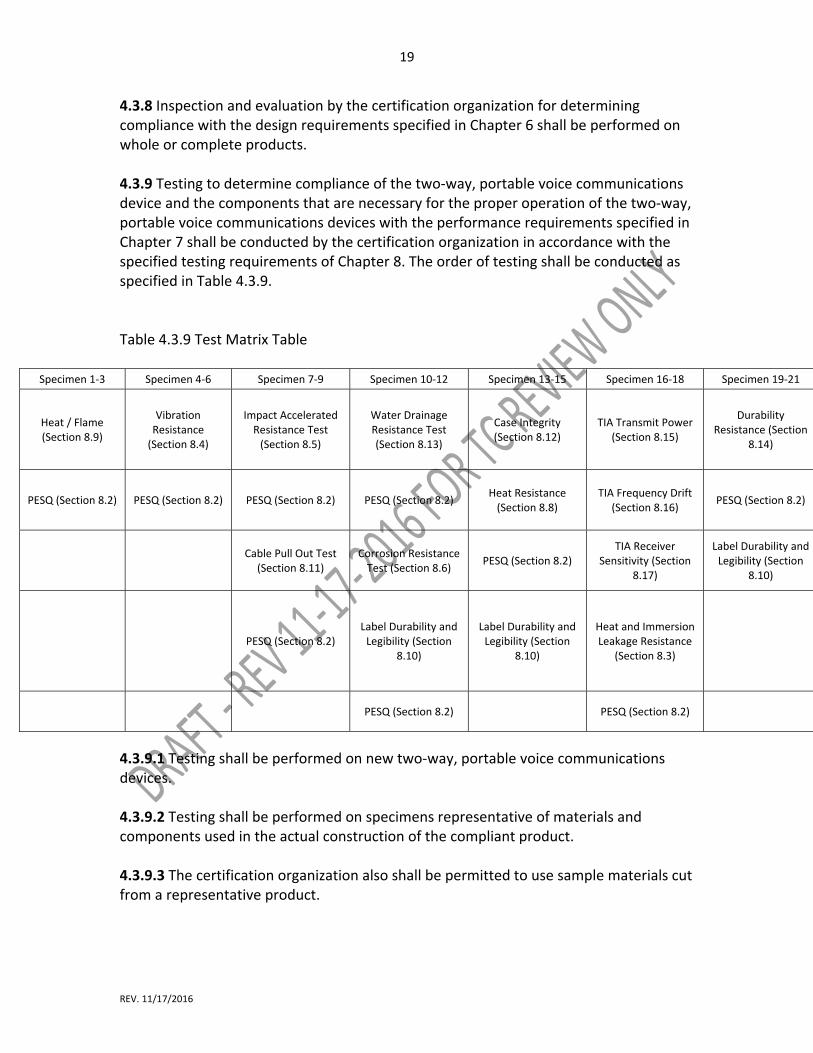
4.3.8 Inspection and evaluation by the certification organization for determining compliance with the design requirements specified in Chapter 6 shall be performed on whole or complete products. 4.3.9 Testing to determine compliance of the two‐way, portable voice communications device and the components that are necessary for the proper operation of the two‐way, portable voice communications devices with the performance requirements specified in Chapter 7 shall be conducted by the certification organization in accordance with the specified testing requirements of Chapter 8. The order of testing shall be conducted as specified in Table 4.3.9. Table 4.3.9 Test Matrix Table
Specimen 1‐3 Specimen 4‐6 Specimen 7‐9 Specimen 10‐12 Specimen 13‐15 Specimen 16‐18 Specimen 19‐21
Heat / Flame (Section 8.9)
Vibration Resistance (Section 8.4)
Impact Accelerated Resistance Test (Section 8.5)
Water Drainage Resistance Test (Section 8.13)
Case Integrity (Section 8.12)
TIA Transmit Power (Section 8.15)
Durability Resistance (Section
8.14)
PESQ (Section 8.2) PESQ (Section 8.2) PESQ (Section 8.2) PESQ (Section 8.2) Heat Resistance (Section 8.8)
TIA Frequency Drift (Section 8.16)
PESQ (Section 8.2)
Cable Pull Out Test
(Section 8.11) Corrosion Resistance Test (Section 8.6)
PESQ (Section 8.2) TIA Receiver
Sensitivity (Section 8.17)
Label Durability and Legibility (Section
8.10)
PESQ (Section 8.2) Label Durability and Legibility (Section
8.10)
Label Durability and Legibility (Section
8.10)
Heat and Immersion Leakage Resistance
(Section 8.3)
PESQ (Section 8.2) PESQ (Section 8.2)
4.3.9.1 Testing shall be performed on new two‐way, portable voice communications devices. 4.3.9.2 Testing shall be performed on specimens representative of materials and components used in the actual construction of the compliant product. 4.3.9.3 The certification organization also shall be permitted to use sample materials cut from a representative product.
20
REV. 11/17/2016
4.3.9.4 Where any manufacturer‐supplied accessories, enhancements or optional components are built into, attached to, or detachable from the two‐way, portable voice communications devices for use in the hazard zone, the certification organization shall inspect and evaluate the two‐way, portable voice communications devices as specified in Chapter 6 and shall test the two‐way, portable voice communications devices as specified in Chapter 8. 4.3.9.5 The two‐way, portable voice communications devices shall meet all the performance requirements specified in Chapter 7 with those accessories and enhancements installed or attached to ensure that the performance and functions of the two‐way, portable voice communications devices are not reduced or otherwise negatively affected. 4.3.10 The certification organization shall accept from the manufacturer, for evaluation and testing for certification, only product or product components that are the same in every respect as the actual final product or product component. 4.3.11 The certification organization shall not allow any modifications, pretreatment, conditioning, or other such special processes of the product or any product component prior to the product’s submission for evaluation and testing by the certification organization. 4.3.12 The certification organization shall not allow the substitution, repair, or modification, other than as specifically permitted herein, of any product or any product component during testing. 4.3.13 The certification organization shall not allow test specimens that have been conditioned and tested for one method to be reconditioned and tested for another test method unless specifically permitted in the test method. 4.3.14 Material changes in the form, fit, or function of a compliant product shall necessitate new inspection and testing to verify compliance to all applicable requirements of this standard that the certification organization determines can be affected by such change. This recertification shall be conducted before labeling the modified product as being compliant with this standard. 4.3.15 The manufacturer shall maintain all design, performance, inspection, and test data from the certification organization used in the certification of the manufacturer’s compliant product. The manufacturer shall provide such data, upon request, to the purchaser or authority having jurisdiction (AHJ). 4.4 Annual Verification of Product Compliance.

21
REV. 11/17/2016
4.4.1 All two‐way, portable voice communications devices that are certified as compliant with this standard shall undergo recertification on an annual basis. This recertification shall include the following: (1) Inspection and evaluation to all design requirements as required by this standard on all manufacturer’s models and components (2) Testing to all performance requirements as required by this standard on all manufacturer’s models and components within the following protocol: (a) Where a test method incorporates testing both before and after preconditioning and the test generates quantitative results, recertification testing shall be limited to the conditioning that yielded the worst case test result during the initial certification for the model or component. (b) Where a test method requires testing of three specimens, a minimum of one specimen shall be tested for annual recertification. (c) Where a test method requires testing of five or more specimens, a minimum of two specimens shall be tested for annual recertification. 4.4.2 Samples of manufacturer’s models and components for recertification acquired from the manufacturer or a component supplier during random and unannounced visits as part of the follow‐up inspection program in accordance with 4.2.9 shall be permitted to be used toward annual recertification. 4.4.3 The manufacturer shall maintain all design, performance inspections and test data from the certification organization used in the recertification of manufacturer’s models and components. The manufacturer shall provide such data, upon request, to the purchaser or AHJ. 4.5 Manufacturers’ Quality Assurance Program. 4.5.1 The manufacturer shall provide and operate a quality assurance program that meets the requirements of this section and that includes a product recall system as specified in 4.2.7.1 and Section 4.8, Manufacturers’ Safety Alert and Product Recall Systems. 4.5.2 The operation of the quality assurance program shall evaluate and test compliant product production to the requirements of this standard to ensure that production remains in compliance. 4.5.3 The manufacturer shall be registered to ISO 9001, Quality management systems — Requirements. 4.5.3.1 Registration to the requirements of ISO 9001, Quality management systems — Requirements, shall be conducted by a registrar that is accredited for personal

22
REV. 11/17/2016
protective equipment in accordance with ISO/IEC 17021, Conformity assessment – Requirements for bodies providing audit and certification of management systems. 4.5.3.2 The scope of the ISO registration shall include at least the design and manufacturing systems management for the personal protective equipment being certified. 4.5.3.3 The registrar shall affix the accreditation mark on the ISO registration certificate. 4.5.4 Any entity that meets the definition of manufacturer specified in 3.3.15 and therefore is considered to be the “manufacturer” but does not manufacture or assemble the compliant product shall meet the requirements specified in Section 4.5. 4.5.5 Where the manufacturer uses subcontractors in the construction or assembly of the compliant product, the locations and names of all subcontractor facilities shall be documented, and the documentation shall be provided to the manufacturer’s ISO registrar and the certification organization. 4.6 Failure Mode and Effects Analysis (FMEA) for Two‐Way, Portable Voice Communications Devices. 4.6.1* An FMEA shall be applied throughout the development process. 4.6.2 The FMEA shall address two‐way, portable voice communications devices and shall identify and prioritize those critical failures that could have a serious effect on the safety and reliability of a two‐way, portable voice communications device in the anticipated operating environments. 4.6.3 The FMEA shall tabulate potential failure modes and their effects on the performance of a two‐way, portable voice communications device. The failure mode shall describe how the system might fail. 4.6.4* The two‐way, portable voice communications device manufacturer shall use FMEA to address the reduction of risk of random and systematic failures of two‐way, portable voice communications devices by using as low as reasonably practical (ALARP) region activities, shown in Figure 4.6.4. The two‐way, portable voice communications device manufacturer shall include the risk priority number (RPN) corresponding to the upper limit of the ALARP region in the FMEA report. Figure 4.6.4. Insert 6.3.4 from NFPA 1801. 4.6.5 Where a two‐way, portable voice communications device system RPN as determined by the manufacturer is above the upper limit of the ALARP region as

23
REV. 11/17/2016
determined by the manufacturer, one or more of the practices specified in 4.6.5.1 shall be permitted. 4.6.5.1 Verification of the manufacturers’ design and testing practices shall include documentation of at least temperature, vibration, and wetness exposure data; hours of operation; and management of change information. 4.6.6 The FMEA report shall be provided to the certification organization. 4.7 Hazards Involving Compliant Product. 4.6.1 The certification organization shall establish procedures to be followed where situation(s) are reported in which a compliant product is subsequently found to be hazardous. These procedures shall comply with the provisions of ISO 27, Guidelines for corrective action to be taken by a certification body in the event of misuse of its mark of conformity, and as modified herein. 4.6.2 Where a report of a hazard involved with a compliant product is received by the certification organization, the validity of the report shall be investigated. 4.6.3 With respect to a compliant product, a hazard shall be a condition, or create a situation, that results in exposing life, limb, or property to a dangerous or imminently dangerous condition. 4.6.4 Where a specific hazard is identified, the determination of the appropriate action for the certification organization and the manufacturer to undertake shall take into consideration the severity of the hazard and its consequences to the safety and health of users. 4.6.5 Where it is established that a hazard is involved with a compliant product, the certification organization shall determine the scope of the hazard, including products, model numbers, serial numbers, factory production facilities, production runs, and quantities involved. 4.6.6 The certification organization’s investigation shall include, but not be limited to, the extent and scope of the problem as it might apply to other compliant product or compliant product components manufactured by other manufacturers or certified by other certification organizations. 4.6.7 The certification organization shall also investigate reports of a hazard where compliant product is gaining widespread use in applications not foreseen when the standard was written. Such applications in turn being ones for which the product was not certified, and no specific scope of application has been provided in the standard,

24
REV. 11/17/2016
and no limiting scope of application was provided by the manufacturer in written material accompanying the compliant product at the point of sale. 4.6.8 The certification organization shall require the manufacturer of the compliant product or the manufacturer of the compliant product component if applicable, to assist the certification organization in the investigation and to conduct its own investigation as specified in Section 4.7, Manufacturers’ Investigation of Complaints and Returns. 4.6.9 Where the facts indicating a need for corrective action are conclusive and the certification organization’s appeal procedures referenced in 4.2.12 have been followed, the certification organization shall initiate corrective action immediately, provided there is a manufacturer to be held responsible for such action. 4.6.10 Where the facts are conclusive and corrective action is indicated, but there is no manufacturer to be held responsible, such as when the manufacturer is out of business or the manufacturer is bankrupt, the certification organization shall immediately notify relevant governmental and regulatory agencies and issue a notice to the user community about the hazard. 4.6.11 Where the facts are conclusive and corrective action is indicated, the certification organization shall take one or more of the following corrective actions: (1) Parties authorized and responsible for issuing a safety alert shall be notified when, in the opinion of the certification organization, such a safety alert is necessary to inform the users. (2) Parties authorized and responsible for issuing a product recall shall be notified when, in the opinion of the certification organization, such a recall is necessary to protect the users. (3) The mark of certification shall be removed from the product. (4) Where a hazardous condition exists and it is not practical to implement the corrective actions in 4.6.11(1), 4.6.11(2), or 4.6.11(3) or where the responsible parties refuse to take corrective action, the certification organization shall notify relevant governmental and regulatory agencies and issue a notice to the user community about the hazard. 4.6.12 The certification organization shall provide a report to the organization or individual identifying the reported hazardous condition and notify that organization or individual of the corrective action indicated or that no corrective action is indicated. 4.7 Manufacturers’ Investigation of Complaints and Returns. 4.7.1 Manufacturers shall provide corrective action in accordance with ISO 9001, Quality management systems — Requirements, for investigating written complaints and returned products.

25
REV. 11/17/2016
4.7.2 Manufacturers’ records of returns and complaints related to safety issues shall be retained for at least 5 years. 4.7.3 Where the manufacturer discovers, during the review of specific returns or complaints, that a compliant product or compliant product component can constitute a potential safety risk to end users and is possibly subject to a safety alert or product recall, the manufacturer shall immediately contact the certification organization and provide all information about its review to assist the certification organization with the investigation. 4.8 Manufacturers’ Safety Alert and Product Recall Systems. 4.8.1 Manufacturers shall establish a written safety alert system and a written product recall system that describes the procedures to be used in the event that they decide or are directed by the certification organization to either issue a safety alert or conduct a product recall. 4.8.2 The manufacturers’ safety alert and product recall systems shall provide the following: (1) The establishment of a coordinator and responsibilities by the manufacturer for the handling of safety alerts and product recalls (2) A method of notifying all dealers, distributors, purchasers, users, and the NFPA about the safety alert or product recall that can be initiated within 1 week following the manufacturer’s decision to issue a safety alert or to conduct a product recall or after the manufacturer has been directed by the certification organization to issue a safety alert or conduct a product recall (3) Techniques for communicating accurately and understandably the nature of the safety alert or product recall and, in particular, the specific hazard or safety issue found to exist (4) Procedures for removing product that is recalled and for documenting the effectiveness of the product recall (5) A plan for repairing or replacing product or for compensating purchasers for returned product Chapter 5 Product Labeling and Information 5.1 Product Label Requirements. 5.1.1 Each compliant two‐way, portable voice communications device shall have a product label permanently and conspicuously attached to the complete assembled product.

26
REV. 11/17/2016
5.1.2 Multiple label pieces shall be permitted in order to carry all statements and information required to be on the product label; however, all label pieces that the product label comprises shall be located adjacent to each other. 5.1.3 The certification organization’s label, symbol, or identifying mark shall be attached to the product label or be part of the product label and shall be placed in a conspicuous location. All letters shall be at least 1.5 mm (1⁄32 in.) in height, and the label, symbol, or identifying mark shall be at least 6 mm (1⁄4 in.) in height. The font Arial in capital le ers shall be used for all label lettering. 5.1.4 All worded portions of the required product label shall be at least in English. 5.1.5 Symbols and other pictorial graphic representations shall be permitted to be used to supplement worded statements on the product label(s). 5.1.6 The following compliance statement shall be legibly printed on the product label:
“THIS TWO‐WAY, PORTABLE VOICE COMMUNICATIONS DEVICE MEETS THE REQUIREMENTS OF NFPA 1802, STANDARD ON TWO‐WAY, PORTABLE VOICE
COMMUNICATIONS DEVICES FOR USE BY EMERGENCY SERVICES PERSONNEL IN THE HAZARD ZONE, 20XX EDITION.
DO NOT REMOVE THIS LABEL!”
5.1.7 Each two‐way portable voice communications device shall be marked directly with the serial number and the year and month of manufacture. 5.1.8 All rechargeable power sources provided by the two‐way portable voice communications device manufacturer shall be marked with a serial number and the year and date of manufacture. 5.1.9 Accessories and components certified shall contain an approval identifier indicating certification to this standard and shall include the year and month of manufacture. 5.2 User Information. 5.2.1 The manufacturer shall provide with each product at least the informational material and user instructions specified in Section 5.2. 5.2.2 At the time of purchase, the manufacturer shall provide to the purchaser an information sheet with each product that documents at least the following:
27
REV. 11/17/2016
(1) Date of manufacture (2) Model number (3) Serial number (4) Lot number, if applicable 5.2.3* Information and materials regarding use shall be provided on at least the following topics: (1) Safety considerations (2) Pre‐use checks (3) Limitations of use (4) Power source requirements, type, and brand (5) Estimated operation time on fully charged power source in each available mode (6) Low‐power source signals and power supply replacement, where applicable (7) Charging and recharging procedures (8) Marking recommendations and restrictions (9) Warranty information (10) Recommended storage practices (11) Mounting on/in vehicles or fire apparatus 5.2.4 Information and operational materials regarding periodic inspections shall be provided on at least inspection frequency and details. 5.2.5 Information and operational materials regarding proper operational use shall be provided. 5.2.6 Information and operational materials regarding periodic maintenance and cleaning shall be provided on at least the following areas: (1) Cleaning instructions and precautions (2) Disinfecting procedures (3) Maintenance frequency and details (4) Guidelines for service and repair 5.2.7 Information and operational materials regarding replacement and retirement considerations for two‐way portable voice communications device and components shall be provided. Chapter 6 Design Requirements 6.1 General Design Requirements
28
REV. 11/17/2016
6.1.1 All devices shall meet the applicable design requirements specified in Section 9.3.6 of NFPA 1221: Standard for the Installation, Maintenance, and Use of Emergency Services Communications Systems, 2016 edition. 6.1.1 All devices shall be interoperable with all optional components including, but not limited to:
(1) Remote speaker microphones (RSM) (2) Self‐contained breathing apparatus
6.1.1.2 The device and any optional component shall be interoperable with each other via wired or wireless communication systems, or both. 6.1.2 This standard shall not apply to voice amplification devices. 6.1.2 All devices shall have at least the applicable design requirements specified in this chapter when inspected and evaluated by the certification organization as specified in 4.3, Inspection and Testing. 6.1.3 All devices shall be capable of continuously operating for a minimum of 8 hours when operated at full transmit power for 5%, active receive at rated volume for 5%, and idle receive for 90% of the time without the power source being changed or recharged, in all transmission modes. 6.1.3.1 Transmission modes shall be permitted to include analog FM. 6.1.3.2 Transmission modes may include, but not be limited to, the following (1) P25 Trunked Phase 1 (2) P25 Phase 2 (3) P25 Conventional 6.1.4 All devices shall have a visual indicator that displays the status of the power source when activated. 6.1.4.1 The Power source visual indicator shall display the following visual information signals for remaining power capacity: (1) 75‐100% (2) 50‐75%, (3) 25‐50% (4) Less than 25% 6.1.4.2 The power source visual indicator shall flash when less than 25% capacity remains.
29
REV. 11/17/2016
6.1.5 All operational selection devices, including but not limited to switches, buttons and keys, shall be rated for not less than 50,000 cycles. 6.1.5.1 Rotary knobs shall be rated for not less than 10,000 cycles. 6.1.6 All operational selection devices shall be designed to prevent unintentional activation, deactivation, and change of operation. 6.1.7 All operational selection devices shall be capable of being switched by a gloved hand. 6.1.7.1 The gloves used for this function test shall be certified as compliant with the structural fire‐fighting glove requirements of NFPA 1971, Standard on Protective Ensembles for Structural Fire Fighting and Proximity Fire Fighting (2018 edition). 6.1.7.2 The gloves shall meet the following requirements: (1) Size Large (2) Outer shell shall be a minimum of 3.25 oz/yd2 American sourced and tanned cowhide (3) Thermal liner system shall be a minimum of 7.5 oz/yd2 6.1.8 All devices shall be capable of both the hazard zone mode and non‐hazard zone mode. 6.1.9 The minimum volume of the device in the hazard zone mode shall be 24 dB +0/‐6 dB below the SPL specified in 6.3.7. 6.1.9.1 All devices shall have the capability to enable hazard zone mode via a programmable switch activation, or also by being pre‐programmed to a channel, talk group or talk path via use of the mode switch. 6.1.10 The device shall include the following: (1) Speaker (2) Microphone 6.2 Controls 6.2.1 The front of the device shall be the side facing the viewer when the push‐to‐talk (PTT) button is located on the left side. 6.2.2 The following controls and features shall be positioned on the top of the device: s (1) Power/volume knob
30
REV. 11/17/2016
(2) Selector knob (3) EAB Emergency alert button (4) External antenna (if so equipped) (5) Display (6) Transmit indicator (7) Programmable selector switch capable of at least three‐positions (8) Programmable selector switch capable of at least two‐positions 6.2.3 Any additional controls or features on the top of the device shall not interfere with any of the required controls 6.2.4 The left side of the device shall include the following: (1) Push‐to‐talk button (PTT) (2) At least one programmable button 6.2.4.1 Any additional controls or features on the left side of the device shall not interfere with any of the required controls. 6.2.5 The right side of the device shall include a component connector that will provide sufficient connections to enable the use of an RSM with the functionality defined in 6.7. 6.2.5.1 Any additional controls or features on the right side of the device shall not interfere with the operation of the required component connector. 6.2.5.2 The device shall have the ability to sense that a previously connected component that conducts, transmit and receive audio paths, is no longer present, then the device’s internal speaker and the microphone will be automatically activated. 6.3 Power/Volume Knob 6.3.1 The device shall have a power/volume knob that shall rotate clockwise to activate the device with and audible and tactile click. 6.3.1.1 The power/volume knob shall be located on the top of the device. 6.3.1.2 The power/volume knob shall control the volume. 6.3.1.2.1 A clockwise rotation of the power/volume knob shall increase the volume. 6.3.1.2.2 A counterclockwise rotation of the power/volume knob shall decrease the volume. 6.3.2 When powered “on” the device shall enter the hazard zone mode.
31
REV. 11/17/2016
6.3.4 Turning off the device shall be accomplished with two separate actions: turning the power/volume knob fully counterclockwise, and then within 5 seconds (‐0/+0.5 seconds) pushing a programmable side button for at least 2 seconds (‐0/+0.5 seconds). 6.3.5 The power/volume knob shall be protected from accidental change of operation and impact damage. 6.3.6 The maximum volume of the device shall be no less than 88 dBA SPL when measured by the method specified in TIA 603E, Section 2.1.20. 6.3.7 When the device is turned off in the hazard zone mode, the device shall have the following voice annunciation: “powering off.” 6.4 Selector Knob 6.4.1 The device shall have a programmable selector knob. 6.4.1.1 The selector knob shall be differentiated in size and shape from the power/volume knob. 6.4.1.2 The selector knob shall have a minimum of 16 positions. 6.4.1.3 There shall be a detent at each position. 6.4.1.4 There shall be hard stops at the minimum and maximum positions. 6.4.1.5 Turning resistance shall be designed to minimize accidental rotation. 6.4.1.6* The selector knob shall change channels, talk groups or talk paths. 6.4.1.7 The AHJ shall be permitted to designate non‐hazard zone channels, talk groups or talk paths. 6.4.1.8 All hazard zone channels, talk groups or talk paths shall use the features and function of hazard zone mode. 6.5 Emergency Alert Button 6.5.1 The emergency alert button shall be located adjacent to the base of the external antenna, if so equipped, or, if not so equipped, adjacent to a guiding device on the top of the radio. 6.5.2 The emergency alert button shall be international orange in color.

32
REV. 11/17/2016
6.5.3 The emergency alert button shall be a minimum of 113 mm2 (0.175 in2) of projected surface area. 6.5.4 The emergency alert button shall be designed to minimize accidental activation. 6.5.5* The emergency alert button shall be designed to be activated by a continuous press of at least 1.5 seconds (±0.5 seconds). 6.5.6 The activation of the emergency alert button shall cause the device to transmit an emergency ID. 6.5.6.1 The activation of the emergency alert button shall be indicated to the user by emitting a distinct audible tone. This tone shall not be used for any other device function. 6.5.6.2 The audible tone shall be at maximum volume. 6.5.6.3 The device shall transmit the emergency ID at the highest RF power the device is capable of transmitting and in compliance with the radio licensing authority. 6.5.6.4 The emergency signal shall use the TSBK protocol when operating in analog conventional mode. 6.5.6.4.1* The AHJ shall be permitted to select one of the following optional protocols in addition to TSBK protocol, based on operational need:
(1) MDC 1200 (2) DTMF (3) P25 (4) G‐Star (5) Other closed proprietary signaling system.
6.5.6.4.2 The emergency signaling scheme shall meet the following requirements [TIA citation]. 6.5.6.5 The device shall have the following capabilities for voice transmission upon activation of the emergency button for transmission of the emergency ID:
(1) Remain on a selected channels, talk groups or talk paths, or (2) Revert to a pre‐programmed emergency ID transmission channels, talk groups or talk paths, and (3) Transmit at the highest RF power the device is capable of transmitting and in compliance with the radio licensing authority.

33
REV. 11/17/2016
6.5.6.6 Upon receipt of an emergency activation from another device, the receiving device shall visually indicate the emergency activation by means of a solid backlit orange display. 6.5.6.6.1 The displayed emergency indication shall remain activated until reset by the activating user or by the dispatch center upon request. 6.5.6.7 Upon receipt of any emergency activation from another device, the receiving device shall have the capability to emit a distinct audible tone not used for any other device function for 3 seconds at maximum volume. 6.5.6.8 Upon receipt of any emergency activation from another device, the receiving device shall display the identification designator of the initiating device. 6.5.6.8.1 Upon receipt of an emergency activation from another device, the receiving device shall have the capability to display alias data by referring to an internally stored ID database. 6.5.6.8.2 Upon receipt of an emergency activation from another device, the receiving device shall have the capability of activating maximum volume regardless of knob position. This shall be permitted to be cancelled at the cessation of the emergency activation. 6.5.6.9 The device shall have the capability of displaying the history of the last 20 received emergency IDs. 6.5.6.9.1 The alias ID information shall be capable of displaying an ID of a minimum of 14 alphanumeric characters. 6.5.6.9.2 The internally stored alias database shall have the capacity of a minimum of 3,000 entries stored in the radio. 6.6 Display 6.6.1 The device shall include a display of at least 8 characters visible without scrolling, and additional characters visible with scrolling and when the backlight is enabled. 6.6.2 The display shall be illuminated by means of backlighting when any device control is manipulated. 6.6.2.1 After being activated, the display shall remain illuminated for 2 seconds, +1/−0 seconds

34
REV. 11/17/2016
6.6.3 The display shall remain illuminated flashing orange on the device that initiated the emergency mode, and illuminated solid orange on all devices that are receiving the emergency message, until reset in accordance with 6.5.6.6.1. 6.6.4 All displays shall be legible in all modes when backlighted and read in a completely dark room from a distance of 2 feet. 6.7 Remote Speaker Microphone 6.7.1 The remote speaker microphone shall be considered an optional component of the device. 6.7.2 The remote speaker microphone shall include a microphone. 6.7.3 The remote speaker microphone shall have a PTT button that meets the requirements of 6.1.7. 6.7.4 The remote speaker microphone shall have a speaker. 6.7.5 The remote speaker microphone shall have a transmit/receive indicator. 6.7.5.1 The transmit/receive indicator shall use the following colors: (1) Green when receiving (2) Red when transmitting 6.7.6 The remote speaker microphone shall have an emergency button that meets the requirements of 6.1.7. 6.7.6.1 The remote speaker microphone emergency button shall be located at the top of the device. 6.7.6.2 The remote speaker microphone emergency button shall meet the requirements specified in 6.5, except 6.5.1. 6.7.7 The remote speaker microphone shall have an orange indicator. 6.7.7.1 The remote speaker microphone orange/red indicator shall display in accordance with 6.6.2 during emergency use. 6.7.7.2 The remote speaker microphone orange/red indicator shall indicate red in accordance with 6.13.11. 6.7.8 Remote speaker microphone emergency indicators shall operate as specified in 6.5.

35
REV. 11/17/2016
6.7.9* The remote speaker microphone shall include a programmable option button that meets the requirements of 6.1.7. 6.7.10 The radio speaker microphone shall be offered in 2 versions at minimum
6.7.10.1 A basic model with no additional audio interface connection for an SCBA mask
per NFPA 1981 Section XXX.
6.7.10.2 A plus model with an additional audio interface connection for an SCBA mask
per NFPA 1981 Section XXX. At minimum one of the following audio interfaces shall be
provided in the plus model:
(1) A wired interface to the SCBA conforming to Table 6.8.4.1 and 6.8.4.2
(2) A wireless interface conforming to 6.17
6.8 Optional Accessory Component Connection to Portable Radio 6.8.1 At a minimum, one of the following interface configurations shall be provided with
the portable radio in order to provide for one or more optional accessory components
to be used in conjunction with the portable radio.
6.8.1.1 A wired interface to the optional accessory component conforming to Table
6.8.4.1 and 6.8.4.2.
6.8.1.2 A wireless interface to the optional accessory component conforming to 6.17.
6.8.2 The portable radio shall provide for an optional accessory component – portable
radio polling protocol to ensure proper operation of the optional accessory component,
and the portable radio shall be the master and the optional accessory components shall
be the slaves.
6.8.2.1 This protocol shall conform to the XXXX protocol
COMMITTEE DECISION POINT: We must pick a specific protocol or else the goal of
interchangeability among various accessories and radios will not be achieved. Some
candidates include: SNMP v3 RFC3410 to 3415; MIL STD 155B; IEEE 1394 (Firewire);
CAN Buss ISO 11898.
6.8.2.2 An optional accessory component shall respond to a connection and presence
verification message in the polling protocol within 500 ms.
36
REV. 11/17/2016
6.8.2.3 The optional accessory component – portable radio protocol and the Personal
Area Network (PAN) implemented in the portable radio and the optional accessory
components shall provide for either a star or daisy chain topology.
6.8.2.4 The PAN shall be implemented as either a wired network, or a wireless network,
or both.
6.8.2.4.1 If the PAN is a wired network, the network shall conform to the following
standards:
(1) The portable radio shall be provided with a female connector that is a 10‐pin miniature version of US MIL‐DTL‐55116 (M55116) or equivalent, and with circuit descriptions as defined in (old) Table 6.8.4.1. (2) Each optional accessory component shall be provided with at least one female connector that is a 10‐pin miniature version of US MIL‐DTL‐55116 (M55116) or equivalent, and with circuit descriptions as defined in (old) Table 6.8.4.1., for the purpose of connecting the optional accessory component to either a portable radio or to another optional accessory component in a daisy chain configuration.
6.8.2.4.2 If the PAN is a wireless network, the network shall conform to 6.17.

37
REV. 11/17/2016
6.8.3 The portable radio shall have a means of detecting a loss of connection with any or all of the optional accessory components. . 6.8.3.1 The loss of connection shall be reported to the portable radio the next time the optional accessory component is polled by the portable radio. 6.8.3.2 Loss of connection to the optional accessory component shall be detected if any one of the following conditions occur: a. Loss of power to the optional accessory component b. Loss of connection to red, green, or orange/red indicator lights, if present on the optional accessory component c. Loss of connection to PTT switch, if present on the optional accessory component d. Loss of connection to the emergency switch, if present on the optional accessory component e. Loss of connection to the programmable button, if present on the optional accessory component f. Loss of connection to the microphone, if present on the optional accessory component g. Loss of connection to the earpiece or loud speaker, if present on the optional accessory component h. Loss of connection to the serial data buss going to the optional accessory component 6.8.1.3 Loss of connection shall be detected if any one of the following conditions occur:
a. Loss of power to the component b. Loss of connection to red, green, or orange/red indicator lights c. Loss of connection to PTT switch d. Loss of connection to programmable button
6.8.4.1 Where the portable radio has a wired PAN, the PAN physical interface shall conform to Table 6.8.4.1.

38
REV. 11/17/2016
Table 6.8.4.1
Pin Assignment
Signal Type Level Tolerance Conditions Notes
J Power + DC +5V ± 0.25V
Minimum capacity: 0.25A ±0.05A (Primary Host) 0.15A±0.05A (Subordinate Device)
A Host Device may be capable of higher current.
K Return Power ‐
DC
Shell Shield / Drain
Tie to Return only at Primary Host end
F Speaker+ AC ≥ 0.5Wrms
RLOAD = 8Ω
G Speaker‐ AC ≥ 0.5Wrms
RLOAD = 8Ω
A Mic+ AC ‐38dBV ±2dBV 94dbSPL at the mic port
B Mic‐ AC
May be connected to 0V reference
D I2C Bus Clock
Digital 0 to +5V ± 0.25V RLOAD > 10kΩ CLOAD < 300pF
5V tolerant i/o, 3.3V Nominal
E I2C Data Digital 0 to +5V ± 0.25V RLOAD > 10kΩ CLOAD < 300pF
5V tolerant i/o, 3.3V Nominal
H
(Hold for shield/gnd if necessary)
C
(Hold for shield/gnd if necessary)

39
REV. 11/17/2016
6.8.4.2 The component connector pin assignments shall be configured as specified in Figure 6.8.4.2.
6.8.4 Failure by the portable radio to detect a proper response that all its connections and functionality are okay from an optional accessory component within 5 seconds shall initiate the connection failsafe protocol. 6.8.4.1 The connection failsafe protocol, shall have a hierarchy of actions that the portable radio shall implement depending on what optional accessory devices are connected. The hierarchy of actions are listed in Table 6.8.4.2. Table 6.8.4.2 Hierarchy of Actions
Opt. Acc. Comp. 1 Opt. Acc. Comp. 2
Connection Condition
Response
RSM No SCBA ear/mic acc
RSM conn. failure
Revert to spkr/mic in portable radio, Alert tone/msg on portable radio
RSM SCBA ear/mic acc
RSM conn. failure
Alert tone/msg on portable radio
SCBA ear/mic acc No RSM SCBA conn. failure
Revert to spkr/mic in portable radio, Alert tone/msg on portable radio
SCBA ear/mic acc RSM SCBA conn. failure
Revert to RSM, Alert tone/msg on portable radio
Body vitals belt, video cam, environm. sensors
Any other Conn. failure Alert tone/msg on portable radio
6.8.4.3 If the connection failsafe protocol is invoked because of a detected loss of communications, then the following events at minimum shall occur.

40
REV. 11/17/2016
6.8.4.3.1 A unique alert tone not used elsewhere shall be played at maximum volume on the portable radio and any optional accessory components which have a speaker which is still operative. If the optional accessory component has an earpiece, the unique alert tone shall be played at the volume level already set by the user for that device. 6.8.4.3.2 This loss of connection shall be display as “ACCSRY FAIL” on the portable radio’s display. 6.8.4.3.3 When “ACCSRY FAIL” status is detected, the displayed message on the portable radio shall be with orange backlighting 6.8.4.3.4 When “ACCSRY FAIL” status is detected, the portable radio and any optional accessory components which have a speaker which is still operative, shall audibly announce, following the unique alert tone, “ACCSRY FAIL” at maximum volume. If the optional accessory component has an earpiece, the announcement shall be played at the volume level already set by the user for that device. 6.8.4.4 The portable radio shall remain in connection failsafe mode until cleared by a specific user action. 6.8.4.4.1 The specific user action to clear the connection failsafe mode shall be permitted to be any of the following: (1) Re‐initiating a pairing with a wireless optional accessory component, (2) Power cycling (which shall initiate a new verification cycle) of the portable radio (3) Connecting a new or repaired wired optional accessory device. 6.9 Voice Announcement 6.9.1 The device shall be equipped with voice announcement in English. 6.9.1.1 Voice announcements in additional languages shall be permitted. 6.9.2 The voice announcement shall be active by default. 6.9.2.1 The default minimum volume of voice announcements shall be at full volume, but shall be permitted to be changed by the AHJ to another volume level, but not less than half maximum volume. 6.9.3 Receive audio shall have priority over channel, talk group or talk path annunciation, and shall override same if they both occur simultaneously, and voice annunciation shall follow within 5 seconds of the last PTT or received audio.
41
REV. 11/17/2016
6.9.4 The channels, talk groups or talk path selection shall be announced when the channel, talk group or talk path selector is rotated to indicate the selected channels, talk groups or talk paths. 6.9.4.1 Announcements shall include the following: (1) Zone/Deck/Bank (2) Channels, talk groups or talk paths (3) Emergency as described in 6.5 (4) Battery at 40% capacity left, and again when battery is at 20% capacity left
(5) Optional component failure (6) Out of range, if applicable in accordance with 6.13 (7) Self‐diagnostic failure as described in 6.15.1.3 (8) Power off
6.9.4.2 Channel, talk group or talk path selection announcement shall permit the use of pre‐recorded voice files or voice synthesis files, or both, as determined by the AHJ. 6.9.4.2.1 Channel, talk group or talk path selection announcements shall allow user created voice files. 6.9.5 Channel, talk group or talk path voice announcements in the hazard zone mode shall be at maximum volume as specified in 6.5.6.7.2. 6.9.6 Voice announcements shall commence within 0.5 seconds of switching channels, talk groups or talk paths. 6.10 Three‐Position Switch 6.10.1 *The three‐position switch shall be capable of being programmed as required by the AHJ. 6.11 Two‐Position Switch 6.11.1 The two‐position Switch shall be capable of being programmed as required by the AHJ. 6.12 Programmable Side Button 6.12.1 The device shall incorporate a minimum of one programmable side button on the display of the Plus model. 6.13 Out‐of‐Range Indication

42
REV. 11/17/2016
6.13.1* Where the device operates on a system that has an out‐of‐range capability, the device shall have an out‐of‐range indication. 6.13.1.1 The device shall have a visual indicator indicating an out‐of‐range condition. All displays shall be backlit flashing red when the device is out of range. 6.13.1.2 The device shall emit an audible tone every 15 seconds (+1/‐1 seconds), and the tone shall last 1 second (+0.5/‐0 seconds) at ??? volume level to indicate an out‐of‐range condition when in an out‐of‐range status. 6.13.1.3 The device shall return to normal display, and the sound shall cease when an out‐of‐range condition is resolved. 6.13.1.4 The device out of range condition shall be indicated within 1 minute of detecting an out of range condition. The AHJ shall have the ability to program a holdoff time of 0 to 45 seconds to eliminate nuisance warnings. 6.14 Transmit and Receive Indicator 6.14.1 The device shall have both a Transmit and Receive indicator. 6.14.1.1 The indicator shall be illuminated solid red when the device is in the transmit mode. 6.14.1.2 The indicator shall be illuminated solid green when the device is receiving a signal. 6.15 Diagnostics 6.15.1 The device shall perform mandatory self‐checks to verify operation when the unit is initially powered up and periodic self‐checks while it remains powered up and periodic self‐diagnostics every 5 minutes at a minimum. 6.15.1.1 The device shall display a visual indication “SLF TEST FAIL” on the display screen when it has failed the self‐check. 6.15.1.2 The display shall be backlit red when the device does not pass the self‐check. 6.15.1.3 The portable radio shall have a voice annunciation “RADIO FAILURE” at maximum volume on the radio and any optional accessory component with a speaker if the self‐diagnostic tests fail. If the optional accessory component has an earpiece, the announcement shall be played at the volume level already set by the user for that device.
43
REV. 11/17/2016
6.15.2 The following functions shall be tested in self‐check: (1)* Remote speaker microphone as stated in 6.8.1 (2)* Loss of antenna connection to the radio (3) Battery has at least 50% of the total capacity available 6.15.3 In addition, the self‐check in 6.15.2 shall include a high temperature exposure test which shall be as follows 6.15.3.1 If the portable radio or the remote speaker microphone is exposed to a temperature of > = 300 ° F (149° Celsius), then that event shall be recorded in the data logger 6.16, and that exposure shall be shown in the self‐check. 6.15.3.1.1 The self‐check shall display “HIGH TEMPERATURE EXPOSURE”. 6.15.3.2 The ANJ may reset the data logger such that the high temperature exposure will not show on subsequent self‐checks until another instance of high temperature exposure is recorded, however the record of each high temperature exposure shall not be erasable from the data logger. 6.15.4 Connecting and optional equipment shall be detected by the device and clear this setting until the next power cycle and perform the optional component check normally. 6.16 Data Logging. 6.16.1 Device shall incorporate data logging in nonvolatile memory and, at a minimum, the following events shall be identified and recorded with the data log and shall also have a time stamp for each event in the data log:
(1) Portable radio is turned on (2) Emergency button activation (3) Activation of user input, button press or switch (4) When power source levels are at initial power on, and then at 75%, 50%, 25%, 10% and 5% of capacity. (5) Portable radio is turned off (6) Selection of channel, talk group, talk path, zone, mode, deck, bank or mission plan (7)* Portable radio or the remote speaker microphone is exposed to a temperature of ≥ 300° F (149° C). (8)* Self‐check failure
6.16.2 The data logging information shall be downloadable by the emergency services organization.
44
REV. 11/17/2016
6.16.3 The data logging shall have a minimum capacity of logging 2000 events. 6.16.4 The data logger shall have a real time clock, settable for date and local time by the AHJ upon the portable radio being initially put into service. 6.16.4.1 The real time clock shall maintain its date and time for a minimum of 2 minutes if the portable radio battery is removed and replaced. 6.16.4.2 If the real time clock should lose power for longer than 2 minutes, then upon power restoration, the portable radio shall emit a voice announcement at full volume “RESET CLOCK” and the portable radio’s display shall show “RESET CLOCK” with an orange backlight. 6.17 Personal Area Network Wireless Interface. 6.17.1 Where the device is equipped with wireless capability to communicate with other components the device shall meet the following requirements: (1) The device shall provide private, point‐to‐point, voice and data communications
between the device and the RSM or optional components including, but not, limited to self‐contained breathing apparatus.
(2) Optional components shall be allowed to stand alone or integrated into other equipment (3) The device shall have a minimum effective range of 1 meter. (4) The device shall operate without degradation in the presence of 20 co‐located like
units with a 5‐meter spherical radius (5)The device shall support the control of all remote speaker functions as required in
NFPA 1802 (6) The device shall support the control of all audio device features as required in NFPA
1981. (7) The device shall only pair with the same unit until user forces it to do otherwise via some definite activation (8) The device pairing shall survive power interruption (9) The device shall be allowed to be manually paired (10) The device shall support audio over standard BT headset profile (11) The device shall support serial data commands over standard BT Serial Protocol (12) The device shall contain data commands as specified in Table 6.17.1.1 (13) The device shall attempt to re‐pair in the case of loss of connection. Table 6.17.1.1. Data Commands.
Command Format Ack Required, Required, Notes
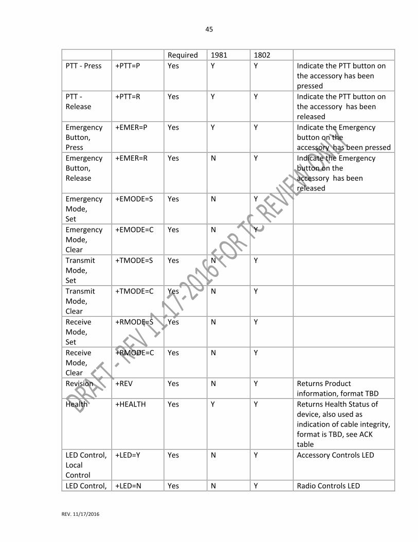
45
REV. 11/17/2016
Required 1981 1802
PTT ‐ Press +PTT=P Yes Y Y Indicate the PTT button on the accessory has been pressed
PTT ‐ Release
+PTT=R Yes Y Y Indicate the PTT button on the accessory has been released
Emergency Button, Press
+EMER=P Yes Y Y Indicate the Emergency button on the accessory has been pressed
Emergency Button, Release
+EMER=R Yes N Y Indicate the Emergency button on the accessory has been released
Emergency Mode, Set
+EMODE=S Yes N Y
Emergency Mode, Clear
+EMODE=C Yes N Y
Transmit Mode, Set
+TMODE=S Yes N Y
Transmit Mode, Clear
+TMODE=C Yes N Y
Receive Mode, Set
+RMODE=S Yes N Y
Receive Mode, Clear
+RMODE=C Yes N Y
Revision +REV Yes N Y Returns Product information, format TBD
Health +HEALTH Yes Y Y Returns Health Status of device, also used as indication of cable integrity, format is TBD, see ACK table
LED Control, Local Control
+LED=Y Yes N Y Accessory Controls LED
LED Control, +LED=N Yes N Y Radio Controls LED

46
REV. 11/17/2016
Remote
LED Control, OFF
+LED=OFF Yes N Y
LED Control, Red, On
+LED=RED Yes
N Y
LED Control, Green, On
+LED=GREEN Yes N Y
LED Control, Blue
+LED=BLUE Yes N Y
LED Control, Yellow
+LED=YELLOW
Yes N Y
6.17.2 Device shall use the acknowledge definition as specified in Table 6.17.2. Table 6.17.2. Acknowledge Definitions.
Code String Notes
OK <cr><lf>OK<cr><lf>
Error <cr><lf>ERROR<cr><lf> Healthy <cr><lf>GOOD<cr><lf> Response if no issues, any other response
triggers cable failsafe protocol
Not Healthy
<cr><lf>FAULT: optional information, total message length not to exceed 128 bytes<cr><lf>
If cable is damagedconnection is lost, Host may never receive this response. ACK format provided to enable additional functionality. HOST device is not required to act on this information. Italics indicates optional message payload
Connection Failsafe Mode
<cr><lf>FAULT: REMOTE DEVICE CONNECTION<cr><lf>
Indicates that a downstream device fault has been detected, for example, the connection is lost between the SCBA and RSM is reported to the Radio with this response
6.17.13 The PAN Wireless Interface shall be Bluetooth 4.0 compliant (or equivalent) wireless stack 6.17.3.1 The wireless Bluetooth stack (or equivalent) shall support the following profiles a specified in Table 6.17.3.1 Table 6.17.3.1. Profiles.
Profile Description
HSP Headset Profile
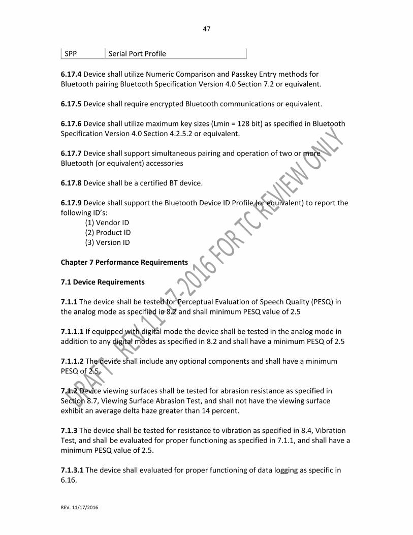
47
REV. 11/17/2016
SPP Serial Port Profile
6.17.4 Device shall utilize Numeric Comparison and Passkey Entry methods for Bluetooth pairing Bluetooth Specification Version 4.0 Section 7.2 or equivalent. 6.17.5 Device shall require encrypted Bluetooth communications or equivalent. 6.17.6 Device shall utilize maximum key sizes (Lmin = 128 bit) as specified in Bluetooth Specification Version 4.0 Section 4.2.5.2 or equivalent. 6.17.7 Device shall support simultaneous pairing and operation of two or more Bluetooth (or equivalent) accessories 6.17.8 Device shall be a certified BT device.
6.17.9 Device shall support the Bluetooth Device ID Profile (or equivalent) to report the following ID’s:
(1) Vendor ID (2) Product ID (3) Version ID
Chapter 7 Performance Requirements 7.1 Device Requirements 7.1.1 The device shall be tested for Perceptual Evaluation of Speech Quality (PESQ) in the analog mode as specified in 8.2 and shall minimum PESQ value of 2.5 7.1.1.1 If equipped with digital mode the device shall be tested in the analog mode in addition to any digital modes as specified in 8.2 and shall have a minimum PESQ of 2.5 7.1.1.2 The device shall include any optional components and shall have a minimum PESQ of 2.5. 7.1.2 Device viewing surfaces shall be tested for abrasion resistance as specified in Section 8.7, Viewing Surface Abrasion Test, and shall not have the viewing surface exhibit an average delta haze greater than 14 percent. 7.1.3 The device shall be tested for resistance to vibration as specified in 8.4, Vibration Test, and shall be evaluated for proper functioning as specified in 7.1.1, and shall have a minimum PESQ value of 2.5. 7.1.3.1 The device shall evaluated for proper functioning of data logging as specific in 6.16.
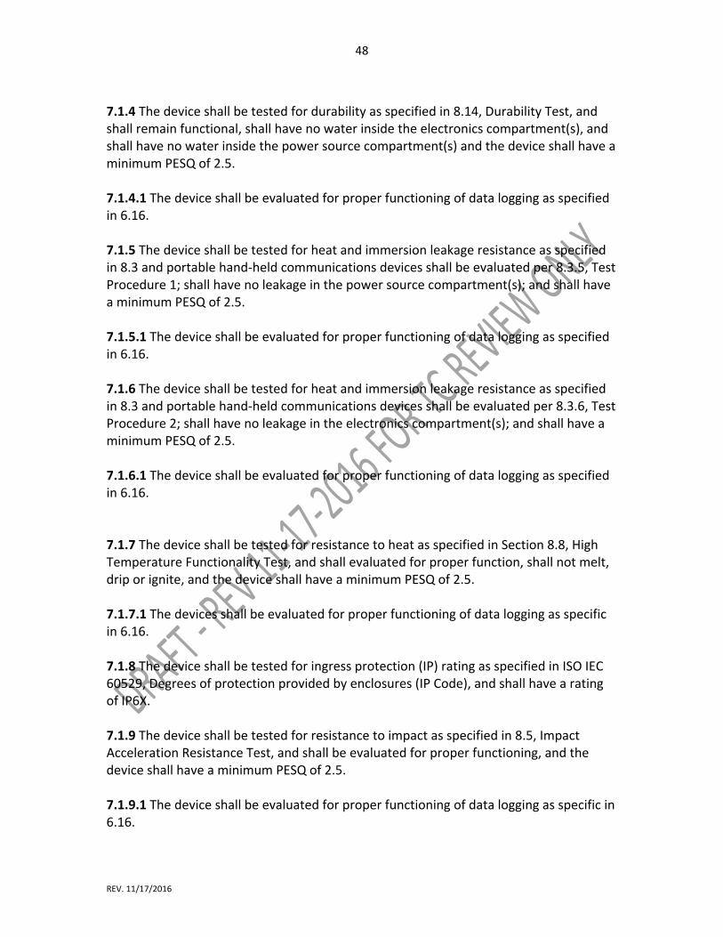
48
REV. 11/17/2016
7.1.4 The device shall be tested for durability as specified in 8.14, Durability Test, and shall remain functional, shall have no water inside the electronics compartment(s), and shall have no water inside the power source compartment(s) and the device shall have a minimum PESQ of 2.5. 7.1.4.1 The device shall be evaluated for proper functioning of data logging as specified in 6.16. 7.1.5 The device shall be tested for heat and immersion leakage resistance as specified in 8.3 and portable hand‐held communications devices shall be evaluated per 8.3.5, Test Procedure 1; shall have no leakage in the power source compartment(s); and shall have a minimum PESQ of 2.5. 7.1.5.1 The device shall be evaluated for proper functioning of data logging as specified in 6.16. 7.1.6 The device shall be tested for heat and immersion leakage resistance as specified in 8.3 and portable hand‐held communications devices shall be evaluated per 8.3.6, Test Procedure 2; shall have no leakage in the electronics compartment(s); and shall have a minimum PESQ of 2.5. 7.1.6.1 The device shall be evaluated for proper functioning of data logging as specified in 6.16. 7.1.7 The device shall be tested for resistance to heat as specified in Section 8.8, High Temperature Functionality Test, and shall evaluated for proper function, shall not melt, drip or ignite, and the device shall have a minimum PESQ of 2.5. 7.1.7.1 The devices shall be evaluated for proper functioning of data logging as specific in 6.16. 7.1.8 The device shall be tested for ingress protection (IP) rating as specified in ISO IEC 60529, Degrees of protection provided by enclosures (IP Code), and shall have a rating of IP6X. 7.1.9 The device shall be tested for resistance to impact as specified in 8.5, Impact Acceleration Resistance Test, and shall be evaluated for proper functioning, and the device shall have a minimum PESQ of 2.5. 7.1.9.1 The device shall be evaluated for proper functioning of data logging as specific in 6.16.
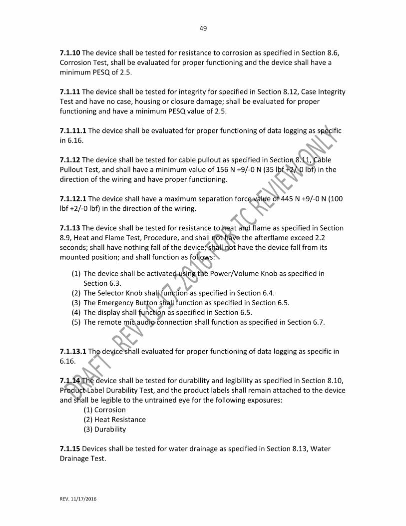
49
REV. 11/17/2016
7.1.10 The device shall be tested for resistance to corrosion as specified in Section 8.6, Corrosion Test, shall be evaluated for proper functioning and the device shall have a minimum PESQ of 2.5. 7.1.11 The device shall be tested for integrity for specified in Section 8.12, Case Integrity Test and have no case, housing or closure damage; shall be evaluated for proper functioning and have a minimum PESQ value of 2.5. 7.1.11.1 The device shall be evaluated for proper functioning of data logging as specific in 6.16. 7.1.12 The device shall be tested for cable pullout as specified in Section 8.11, Cable Pullout Test, and shall have a minimum value of 156 N +9/‐0 N (35 lbf +2/‐0 lbf) in the direction of the wiring and have proper functioning. 7.1.12.1 The device shall have a maximum separation force value of 445 N +9/‐0 N (100 lbf +2/‐0 lbf) in the direction of the wiring. 7.1.13 The device shall be tested for resistance to heat and flame as specified in Section 8.9, Heat and Flame Test, Procedure, and shall not have the afterflame exceed 2.2 seconds; shall have nothing fall of the device; shall not have the device fall from its mounted position; and shall function as follows:
(1) The device shall be activated using the Power/Volume Knob as specified in Section 6.3.
(2) The Selector Knob shall function as specified in Section 6.4. (3) The Emergency Button shall function as specified in Section 6.5. (4) The display shall function as specified in Section 6.5. (5) The remote mic audio connection shall function as specified in Section 6.7.
7.1.13.1 The device shall evaluated for proper functioning of data logging as specific in 6.16. 7.1.14 The device shall be tested for durability and legibility as specified in Section 8.10, Product Label Durability Test, and the product labels shall remain attached to the device and shall be legible to the untrained eye for the following exposures: (1) Corrosion (2) Heat Resistance (3) Durability 7.1.15 Devices shall be tested for water drainage as specified in Section 8.13, Water Drainage Test.

50
REV. 11/17/2016
7.1.15.1 The device shall be evaluated for proper functioning of data logging as specific in 6.16. 7.1.16 Devices shall be tested for intrinsic safety as specified in TIA STANDARD TIA‐4950‐A Requirements for Battery‐Powered, Portable Land Mobile Radio Applications in Class I, II and III, Division 1, Hazardous (Classified) Locations. 7.1.16.1 The device shall earn a rating for use in the following hazard locations: Class I, Division 1, Groups C, D Class I, Division 2, Groups A, B, C, D Class II, Divisions 1 and 2, Groups E, F, G Class III, Divisions 1 and 2 7.17 After pairing or connecting a remote speaker mic, or optional component, the device (ed. Device is the radio) shall be evaluated for proper functioning; and shall function as follows: (1) The device shall be activated using the Power/Volume Knob as specified in Section 6.3. (2) The Selector Knob shall function as specified in Section 6.4. (3) The Emergency Button shall function as specified in Section 6.5. (4) The display shall function as specified in Section 6.5.
7.17.1 After pairing or connecting the remote speaker mic shall function as specified in Section 6.7. 7.17.2 After pairing or connecting any optional component attached to the device shall be evaluated for proper functioning. 7.18 The wired connection shall be tested for cable pullout as specified in Section 8.11, Cable Pullout Test, and shall have a minimum value of 156 N +9/‐0 N (35 lbf +2/‐0 lbf) in the direction of the wiring and have proper functioning. 7.18.1 The wired connection shall have a maximum separation force value of 34 N +?/‐0 N (25 lbf +?/‐0 lbf) in the direction of the coupling.
Chapter 8 Test Methods 8.1 Sample Preparation. 8.1.1 Application. 8.1.1.1 The sample preparation procedures contained in this section shall apply to each test method in this chapter, as specifically referenced in the sample preparation section of each test method.

51
REV. 11/17/2016
8.1.1.2 Only the specific sample preparation procedure or procedures referenced in the sample preparation section of each test method shall be applied to that test method. 8.1.1.3 Samples shall be complete devices. 8.1.1.4 Specimens for testing shall be complete devices. 8.1.1.5 A minimum of three specimens shall be tested. 8.1.2 Room Temperature Conditioning Procedure. 8.1.2.1 Specimens shall be conditioned at a temperature of 22°C ± 3°C (72°F ± 5°F) and relative humidity (RH) of 50 percent ± 25 percent for at least 4 hours. 8.1.2.2 Specimens shall be tested within 5 minutes after removal from conditioning. 8.1.3 Cold Temperature Conditioning Procedure. 8.1.3.1 Specimens shall be exposed to a temperature of −20°C +0/−3°C (−4°F +0/−5°F) for at least 4 hours. 8.1.3.2 Testing shall begin within 30 seconds of the specimens being removed from the conditioning. 8.1.4 Elevated Temperature Conditioning Procedure. 8.1.4.1 Specimens shall be exposed to a temperature of 71°C +1/−0°C (160°F +2/−0°F) for at least 4 hours. 8.1.4.2 Testing shall begin within 30 seconds of the specimens being removed from the conditioning. 8.2 Perceptual Evaluation of Speech Quality (PESQ) Test. 8.2.1 Apparatus 8.2.1 Apparatus 8.2.1.1 Testing shall be conducted in a chamber having the following minimum characteristics:
(1) Construction shall be hemi‐anechoic. (2) Ambient noise level inside chamber shall be NC‐25. (3) Walls and ceiling shall be ≥90 percent absorptive for 100 Hz. (4) Clearance from test specimens shall be ≥1 m.
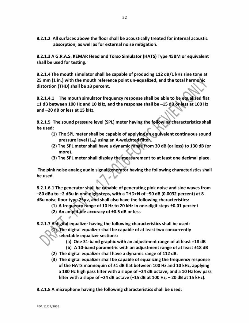
52
REV. 11/17/2016
8.2.1.2 All surfaces above the floor shall be acoustically treated for internal acoustic
absorption, as well as for external noise mitigation. 8.2.1.3 A G.R.A.S. KEMAR Head and Torso Simulator (HATS) Type 45BM or equivalent shall be used for testing. 8.2.1.4 The mouth simulator shall be capable of producing 112 dB/1 kHz sine tone at 25 mm (1 in.) with the mouth reference point un‐equalized, and the total harmonic distortion (THD) shall be ≤3 percent. 8.2.1.4.1 The mouth simulator frequency response shall be able to be equalized flat ±1 dB between 100 Hz and 10 kHz, and the response shall be –15 dB or less at 100 Hz and –20 dB or less at 15 kHz. 8.2.1.5 The sound pressure level (SPL) meter having the following characteristics shall be used:
(1) The SPL meter shall be capable of applying an equivalent continuous sound pressure level (Leq) using an A‐weighted filter.
(2) The SPL meter shall have a dynamic range from 30 dB (or less) to 130 dB (or more).
(3) The SPL meter shall display the measurement to at least one decimal place. The pink noise analog audio signal generator having the following characteristics shall be used. 8.2.1.6.1 The generator shall be capable of generating pink noise and sine waves from –80 dBu to –2 dBu in one‐digit steps, with a THD+N of –90 dB (0.0032 percent) at 8 dBu noise floor type 25µv, and shall also have the following characteristics:
(1) A frequency range of 10 Hz to 20 kHz in one‐digit steps ±0.01 percent (2) An amplitude accuracy of ±0.5 dB or less
8.2.1.7 A digital equalizer having the following characteristics shall be used:
(1) The digital equalizer shall be capable of at least two concurrently selectable equalizer sections:
(a) One 31‐band graphic with an adjustment range of at least ±18 dB (b) A 10‐band parametric with an adjustment range of at least ±18 dB
(2) The digital equalizer shall have a dynamic range of 112 dB. (3) The digital equalizer shall be capable of equalizing the frequency response
of the HATS mannequin of ±1 dB flat between 100 Hz and 10 kHz, applying a 180 Hz high pass filter with a slope of –24 dB octave, and a 10 Hz low pass filter with a slope of –24 dB octave (–15 dB at 100 Hz, – 20 dB at 15 kHz).
8.2.1.8 A microphone having the following characteristics shall be used:
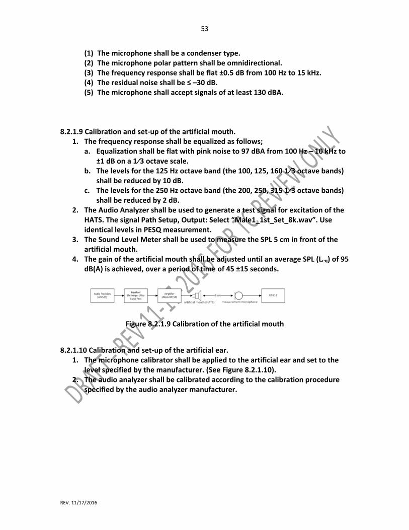
53
REV. 11/17/2016
(1) The microphone shall be a condenser type. (2) The microphone polar pattern shall be omnidirectional. (3) The frequency response shall be flat ±0.5 dB from 100 Hz to 15 kHz. (4) The residual noise shall be ≤ –30 dB. (5) The microphone shall accept signals of at least 130 dBA.
8.2.1.9 Calibration and set‐up of the artificial mouth.
1. The frequency response shall be equalized as follows; a. Equalization shall be flat with pink noise to 97 dBA from 100 Hz – 10 kHz to
±1 dB on a 1⁄3 octave scale. b. The levels for the 125 Hz octave band (the 100, 125, 160 1⁄3 octave bands)
shall be reduced by 10 dB. c. The levels for the 250 Hz octave band (the 200, 250, 315 1⁄3 octave bands)
shall be reduced by 2 dB. 2. The Audio Analyzer shall be used to generate a test signal for excitation of the
HATS. The signal Path Setup, Output: Select “Male1_1st_Set_8k.wav”. Use identical levels in PESQ measurement.
3. The Sound Level Meter shall be used to measure the SPL 5 cm in front of the artificial mouth.
4. The gain of the artificial mouth shall be adjusted until an average SPL (Leq) of 95 dB(A) is achieved, over a period of time of 45 ±15 seconds.
Figure 8.2.1.9 Calibration of the artificial mouth
8.2.1.10 Calibration and set‐up of the artificial ear.
1. The microphone calibrator shall be applied to the artificial ear and set to the level specified by the manufacturer. (See Figure 8.2.1.10).
2. The audio analyzer shall be calibrated according to the calibration procedure specified by the audio analyzer manufacturer.

54
REV. 11/17/2016
Figure 8.2.1.10 Calibration of the Artificial Ear 8.2.1.11 PESQ measurement setup.
1. The PESQ measurement shall be activated in the audio analyzer. 2. Four excitation speech signals, 2 male and 2 female, shall be selected by the
audio analyzer. (specific signals need to be determined out of 12) Brian researching.
3. The mode shall be narrowband. 4. Automatic gain control shall be disabled. 5. The average of the 4 PESQ readings shall be calculated and reported. See
Figure 8.2.1.11.
Figure 8.2.1.11 PESQ measurement reading 8.2.1.12 LMR Radio Transmission Path.
1. The audio signal shall be fed to the transmitting specimen via the NFPA Standard Connector [Connector specified in NFPA 1802?].
2. The audio signal shall be measured at the NFPA Standard Connector of the receiving specimen.
3. The signal level of the audio analyzer shall be set to 100 mV RMS. 4. The measurement shall be started and the PESQ reading measured and
reported [see Figure 8.2.1.12].
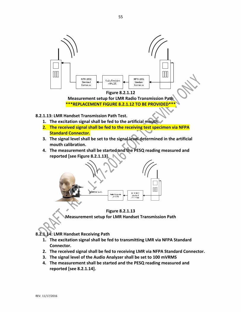
55
REV. 11/17/2016
Figure 8.2.1.12
Measurement setup for LMR Radio Transmission Path ***REPLACEMENT FIGURE 8.2.1.12 TO BE PROVIDED***
8.2.1.13: LMR Handset Transmission Path Test.
1. The excitation signal shall be fed to the artificial mouth. 2. The received signal shall be fed to the receiving test specimen via NFPA
Standard Connector. 3. The signal level shall be set to the signal level determined in the artificial
mouth calibration. 4. The measurement shall be started and the PESQ reading measured and
reported [see Figure 8.2.1.13].
Figure 8.2.1.13 Measurement setup for LMR Handset Transmission Path
8.2.1.14: LMR Handset Receiving Path
1. The excitation signal shall be fed to transmitting LMR via NFPA Standard Connector.
2. The received signal shall be fed to receiving LMR via NFPA Standard Connector. 3. The signal level of the Audio Analyzer shall be set to 100 mVRMS 4. The measurement shall be started and the PESQ reading measured and
reported [see 8.2.1.14].

56
REV. 11/17/2016
Figure 8.2.1.14
Measurement setup for LMR Handset Receiving Path 8.2.1.15: LMR RSM Transmission Path
1. The excitation signal shall be fed to the artificial mouth. 2. The acoustic signal shall be fed via RSM to transmitting LMR. 3. The signal of receiving LMR shall be fed to Audio Analyzer. 4. The signal level shall be set to the signal level determined in the artificial
mouth calibration. 5. The measurement shall be started and the PESQ reading measured and
reported [see Figure 8.2.1.15].
Figure 8.2.1.15 Measurement setup for LMR RSM Transmission Path
8.3 Heat and Immersion Leakage Resistance 8.3.1 Application. This test method shall apply to all devices. 8.3.2 Samples. 8.3.2.1 Samples shall be complete devices. 8.3.2.2 Samples shall be conditioned as specified in 8.1.2.
RSM mounted in front of
artificial mouth as
specified by manufacture.
Manufacture shall provide
fixture.
57
REV. 11/17/2016
8.3.3 Specimens. 8.3.3.1 Specimens for testing shall be complete devices. 8.3.3.2 A minimum of three specimens shall be tested. 8.3.4 Apparatus. 8.3.4.1 A test oven having minimum dimensions of 915 mm depth × 915mm width × 1220mm height (36 in. depth × 36 in. width × 48 in. height) shall be provided. 8.3.4.1.1 The test oven shall have an airflow rate of 38 m/min to 76 m/min (125 ft/min to 250 ft/min) at the standard temperature and pressure of 22°C (72°F) at 1 atmosphere measured at the center point of the oven. 8.3.4.1.2 A test thermocouple shall be positioned so that it is level with the horizontal centerline of a mounted specimen. 8.3.4.2 A test water container capable of covering the uppermost point of the specimen with a depth of 1.5 m (4.9 ft) of water shall be provided. 8.3.4.2.1 The water container shall maintain the devices at that depth. 8.3.4.2.2 The water temperature shall be 22°C ± 3°C (72°F ± 5°F). 8.3.5 Test Procedure 1. 8.3.5.1 Specimens shall be placed in the test oven that has been preheated to 177°C +5/−0°C (350°F +10/−0°F). Test exposure me of 15 minutes shall begin. 8.3.5.2 After the test exposure time of 15 minutes, the specimens shall be removed from the oven and within 30 seconds shall be immersed in the test water container for 15 minutes. After 15 minutes, the specimens shall be removed from the test water container and shall be wiped dry. 8.3.5.3 Specimens shall be subject to 8.3.5.1 and 8.3.5.2 for six complete cycles. 8.3.5.4 After the sixth cycle, the power source compartment of the specimens shall be opened and shall be inspected for water leakage to determine pass or fail performance. Where the device does not fail this portion of the test, the power source shall be reinstalled. 8.3.5.5 After the sixth cycle, The PESQ measurement shall be conducted as specified in 8.2 to determine the pass or fail performance.
58
REV. 11/17/2016
8.3.5.6 Following the PESQ measurement, the specimen shall be operated to the manufacturer’s instructions as specified in 6.2 thru 6.7 to determine the proper functioning to determine the pass or fail performance. 8.3.6 Test Procedure 2. 8.3.6.1 Following test procedure 1, the specimens shall be re‐immersed in the test water container for an additional 5 minutes +30/−0 seconds. The power source compartment(s), if so equipped, shall be opened, and the power source shall not be installed. 8.3.6.2 After the 5‐minute immersion, the specimens shall be removed from the test water container and shall be wiped dry. 8.3.6.3 The electronic compartment(s) of the specimens shall be opened and inspected for water leakage to determine pass or fail performance. 8.3.7 Report. 8.3.7.1 The PESQ Value measured after Heat and Immersion Leakage Test shall be recorded and reported. 8.3.7.2 The functioning of the specimens shall be recorded and reported. 8.3.8 Interpretation 8.3.8.1 Pass or Fail performance shall be determined for each specimen. 8.3.8.2 Failing performance of one or more specimens shall constitute failing performance for this test. 8.4 Vibration Test. 8.4.1 Application. This test method shall apply to all devices. 8.4.2 Samples. Samples shall be complete Devices. 8.4.2.1 Samples shall be conditioned as specified in 8.1.2. 8.4.3 Specimens. 8.4.3.1 Specimens for testing shall be complete devices.
59
REV. 11/17/2016
8.4.3.2 A minimum of three specimens shall be tested. 8.4.3.3 Specimens shall be conditioned at a temperature of 22°C ± 3°C (72°F ± 5°F), and a relative humidity of 50 percent ± 25 percent, for at least 4 hours. 8.4.3.4 Specimens shall be tested within 5 minutes after removal from conditioning. 8.4.4 Apparatus. 8.4.4.1 Product shall be tested on a typical package tester within the compartments specified in 8.3.4.2 through 8.3.4.4. 8.4.4.2 Compartments shall be set up as specified in Figure 8.4.4.2(a) and Figure 8.4.4.2(b). FIGURE 8.4.4.2(a) Vibration Table Compartments — Top View (Not to Scale). FIGURE 8.4.4.2(b) Vibration Table Compartments — Side View (Not to Scale). 8.4.4.2.1 The sides and the base of the compartments shall be constructed of nominal 6 mm (1⁄4 in.) stainless steel, and the top of the compartments shall remain open. 8.4.4.2.2 There shall be no burrs, sharp edges, surface discontinuities, or fasteners on the internal surfaces of the holding boxes. 8.4.4.3 The large compartments shall encase the complete devices that are larger than 5161 mm2 (8 in2). 8.4.4.4 The small compartments shall encase the complete devices that are smaller than 5161 mm2 (8 in2). 8.4.5 Procedure. 8.4.5.1 Test specimens shall be placed unrestrained in the compartments specified in 8.3.4.2. 8.4.5.2 Test specimens shall not be tied down. 8.4.5.3 The basic movement of the bed of the test table shall be a 25 mm, orbital path such as can be obtained on a standard package tester operating in synchronous mode at 250 rpm ± 5 rpm. 8.4.5.4 The test duration shall be 3 hours.

60
REV. 11/17/2016
8.4.5.5 The PESQ measurement shall be conducted as specified in 8.2 to determine the pass or fail performance. 8.4.5.6 Following the PESQ measurement, the specimen shall be operated to the manufacturer’s instructions to determine the proper functioning as specified in 7.1.1 to determine the pass or fail performance. 8.4.5.7 Specimens shall be operated according to the manufacturer’s instructions to determine the proper functioning for data logging as specified in 6.16 to determine pass or fail performance. 8.4.6 Report 8.4.6.1 The PESQ Value measured after Vibration Resistance Test shall be recorded and reported. 8.4.6.2 The functioning of the specimens shall be recorded and reported. 8.4.7 Interpretation 8.4.7.1 Pass or Fail performance shall be determined for each specimen. 8.4.7.2 Failing performance of one or more specimens shall constitute failing performance for this test. 8.5 Impact Acceleration Resistance Test. 8.5.1 Application. This test method shall apply to all devices. 8.5.2 Samples. Samples shall be complete devices. 8.5.2.1 Samples shall be conditioned as specified in 8.1.2. 8.5.3 Specimens. 8.5.3.1 Specimens for testing shall be complete devices. 8.5.3.2 A minimum of three specimens shall be tested. 8.5.4 Procedure. 8.5.4.1 Three specimens of product shall be subjected to a series of impact acceleration tests.
61
REV. 11/17/2016
8.5.4.1.1 One test specimen for ambient temperature conditioning shall be exposed to a temperature of 22°C ± 3°C (72°F ± 5°F), for at least 4 hours. 8.5.4.1.2 One test specimen for cold temperature conditioning shall be exposed to a temperature of −20°C ± 1°C (−4°F ± 2°F), for at least 4 hours. 8.5.4.1.3 One test specimen for elevated temperature conditioning shall be exposed to a temperature of 60°C ± 1°C (140°F ± 2°F), for at least 4 hours. 8.5.4.2 Each product tested shall be complete with power source. 8.5.4.3 After conditioning, product shall be turned to the “on” position. Testing shall begin within 30 seconds of removal from conditioning. 8.5.4.4 Following each conditioning, the product shall be dropped a total of eight times from a distance of 2 m (6.5 ft) onto a concrete surface so that impact is on each face and on one corner and one edge of the product. 8.5.4.5 The entire series of drops shall be completed within 10 minutes of removal from conditioning. 8.5.4.6 Specimens shall be evaluated to determine that the device enclosure has not incurred damage that affects normal operation or enclosure integrity. 8.5.4.7 The PESQ measurement shall be conducted as specified in 8.2 to determine the pass or fail performance. 8.5.4.8 Following the PESQ measurement, the specimen shall be operated to the manufacturer’s instructions as specified in 6.2 thru 6.7 to determine the proper functioning to determine the pass or fail performance. 8.5.4.9 Specimens shall be operated according to the manufacturer’s instructions to determine the proper functioning for data logging as specified in 6.16 to determine pass or fail performance. 8.5.5 Report 8.5.5.1 The PESQ Value measured after Accelerated Impact Resistance Test shall be recorded and reported. 8.5.5.2 The functioning of the specimens shall be recorded and reported. 8.5.6 Interpretation

62
REV. 11/17/2016
8.5.6.1 Pass or Fail performance shall be determined for each specimen. 8.5.6.2 Failing performance of one or more specimens shall constitute failing performance for this test. 8.6 Corrosion Test. 8.6.1 Application. This test method shall apply to all devices. 8.6.2 Samples. Samples shall be complete devices. 8.6.3 Specimens. 8.6.3.1 Specimens for testing shall be complete devices. 8.6.3.2 A minimum of three specimens shall be tested. 8.6.3.3 Specimens shall be conditioned at a temperature of 22°C ± 3°C (72°F ± 5°F), and a relative humidity of 50 percent, ± 25 percent, for at least 4 hours. 8.6.3.4 Specimens shall be tested within 5 minutes after removal from conditioning. 8.6.4 Procedure. 8.6.4.1 Specimens shall be tested in accordance with ASTM B117, Standard Practice for Operating Salt Spray (Fog) Apparatus. Salt spray shall be 5 percent saline solution, and the test exposure shall be for 48 hours, +30/−0 minutes. The chamber shall be stabilized at a temperature of 35°C ± 3°C (95°F ± 5°F). 8.6.4.2 Specimens shall be placed in the chamber in the typical operating position as used by first responders, as specified by the manufacturer. 8.6.4.3 At the conclusion of the salt spray period, specimens shall be stored in an environment of 22°C ± 3°C (72°F ± 5°F) at 50 percent ± 5 percent, relative humidity for a minimum of 48 hours. 8.6.4.4 Following the conditioning period, specimens shall be tested within 60 seconds of removal from conditioning. 8.6.5 The PESQ measurement shall be conducted as specified in 8.2 to determine the pass or fail performance. 8.6.6 The specimen shall be operated to the manufacturer’s instructions as specified in 6.2 thru 6.7 to determine the proper functioning to determine the pass or fail performance.

63
REV. 11/17/2016
8.6.7 Report 8.6.7.1 The PESQ Value measured after Corrosion Test shall be recorded and reported. 8.6.7.2 The functioning of the specimens shall be recorded and reported. 8.6.8 Interpretation 8.6.8.1 Pass or Fail performance shall be determined for each specimen. 8.6.8.2 Failing performance of one or more specimens shall constitute failing performance for this test. 8.7 Viewing Surface Abrasion Test. 8.7.1 Application. This test shall apply to all devices. 8.7.2 Samples. Samples shall be complete viewing surfaces or representative plaques from devices. 8.7.3 Specimens. 8.7.3.1 Specimens for testing shall be complete devices’ viewing surfaces or representative plaques. 8.7.3.2 Four specimens shall be taken. 8.7.3.3 One of the specimens shall be the set‐up specimen. 8.7.3.4 The test specimen shall include all of the following criteria: (1) The specimen shall be a square measuring 50 mm × 50 mm (2 in. × 2 in.). (2) At least 38 mm (11⁄2 in.) of the 50 mm × 50 mm (2 in. × 2 in.) square shall be taken from the viewing surface. 8.7.3.5 Each of the specimens shall be cleaned in the following manner: (1) The specimen shall be rinsed with clean tap water. (2) The specimen shall be washed with a solution of nonionic/ low‐phosphate detergent and water using a clean, soft gauze pad. (3) The specimen shall be rinsed with de‐ionized water. (4) The specimen shall be blown dry with clean compressed air or nitrogen.
64
REV. 11/17/2016
8.7.3.6 Samples shall be conditioned as specified in 8.1.2. 8.7.3.7 Specimens shall be tested within 5 minutes after removal from conditioning. 8.7.4 Apparatus. The test apparatus shall be constructed in accordance with Figure 8.7.4(a) and Figure 8.7.4(b). FIGURE 8.7.4(a) Lens Abrasion Tester. FIGURE 8.7.4(b) Lens Abrasion Tester (details). 8.7.5 Procedure. 8.7.5.1 The haze of the specimen shall be measured using a haze meter in accordance with ASTM D 1003, Standard Test Method for Haze and Luminous Transmittance of Transparent Plastics, and recorded with the following additions: (1) The haze shall be measured in the middle 2 mm2 of the specimen. (2) The specimen shall be repositioned to achieve the maximum haze value within the area defined in 8.7.5.1(1). (3) The haze meter shall have a specified aperture of 22 mm. (4) The haze meter shall have a visual display showing 0.1 percent resolution. (5) The haze meter shall be calibrated before and after each day’s use following procedures specified in ASTM D 1003, Standard Test Method for Haze and Luminous Transmittance of Transparent Plastics. 8.7.5.2 The set‐up specimen shall be placed cover side up in the test apparatus specimen holder. The specimen holder shall be configured with a flat surface under the lens or with an inner radius support. 8.7.5.3 The pad holder shall consist of a cylinder 9.5 mm (0.4 in.) high and 25 mm (1 in.) in diameter with a radius of curvature equal to the radius of curvature of the outside of the lens in the viewing area ±0.25 diopter. This cylinder shall be rigidly affixed to the stroking arm by a #10‐32 UNF threaded rod. 8.7.5.4 The pad shall be a Blue Streak M306M wool felt polishing pad 23 mm (0.9 in.) in diameter. 8.7.5.5 The abrasive disc shall be made from 3M Part Number 7415, Wood Finishing Pad. A disc 23 mm (0.9 in.) in diameter shall be cut from the abrasive sheet. The marked side of the disc shall be placed against the pad. Care shall be exercised to maintain this orientation for each abrasive disc throughout the testing. 8.7.5.6 The pad holder, pad, and abrasive disc shall be installed on the stroking arm. The stroking arm shall be leveled to ±3 degrees by adjusting the threaded pin. The pin shall

65
REV. 11/17/2016
be secured to prevent rotation of the pad holder. The axis of curvature of the pad holder shall be coincident with the axis of curvature of the lens. 8.7.5.7 The stroking arm shall be counterbalanced with the pad holder, pad, and abrasive disc in place. 8.7.5.8 The set‐up specimen shall be replaced with one of the three specimens to be tested. 8.7.5.9 A 1000 g ± 5 g (2.7 lb ± 0.16 oz.) test weight shall be installed on the pin above the test sample. 8.7.5.10 The test shall be run for 200 cycles ± 1 cycle. One cycle shall consist of a complete revolution of the eccentric wheel. 8.7.5.11 The length of stroke shall be 14mm (1⁄2 in.), producing a pa ern 38 mm (11⁄2 in.) long. The frequency of the stroke shall be 60 cycles per minute ± 1 cycle per minute. The center of the stroke shall be within ±2 mm (±0.08 in.) of the center of the specimen. 8.7.5.12 The specimen shall be removed and cleaned following the test procedure. The abrasive disc shall be discarded. 8.7.5.13 The haze of the sample shall be measured following the test procedure. 8.7.5.14 The delta haze shall be calculated by subtracting the initial haze from the final haze. 8.7.5.15 The testing steps specified in 8.7.5.8 through 8.7.5.14 shall be repeated five times with a new sample and abrasive disc. 8.7.6 Report. The three delta haze values shall be averaged, recorded, and reported. 8.7.7 Interpretation. The average delta haze shall be evaluated to determine pass or fail. 8.8 High Temperature Functionality Test. 8.8.1 Application. This test method shall apply to all devices. 8.8.2 Samples. Samples shall be complete devices. 8.8.2.1 Samples shall be conditioned as specified in 8.1.2. 8.8.3 Specimens.
66
REV. 11/17/2016
8.8.3.1 Specimens for testing shall be complete devices. 8.8.3.2 A minimum of three specimens shall be tested. 8.8.3.3 Samples shall be conditioned as specified in 8.1.2. 8.8.3.4 Specimens shall be tested within 5 minutes after removal from conditioning. 8.8.4 Apparatus. The test oven shall be as specified in ISO 17493, Clothing and equipment for protection against heat — Test method for convective heat resistance using a hot air circulating oven. 8.8.5 Procedure. 8.8.5.1 Testing shall be performed in accordance with ISO 17493, Clothing and equipment for protection against heat — Test method for convective heat resistance using a hot air circulating oven, using the following parameters: (1) A test fixture capable of accommodating the device being tested shall be used. (2) The test temperature shall be 260°C, +6/−0°C (500°F, +10/−0°F). (3) Specimens shall be mounted in the “as worn” position on a test fixture and shall not touch any oven surface. (4) The test fixture shall not degrade the oven recovery time. (5) The test fixture shall be designed to allow the specimens to be attached in the same configuration as the specimens’ mounting assembly attaches to the specimens. 8.8.5.2 The test fixture with the specimen attached shall be placed in the test oven perpendicular with the front surface facing perpendicular to the airflow of the oven. 8.8.5.3 The specimen shall be set to the “on” mode. 8.8.5.4 There shall be no obstructions between the specimen and the airflow. The test fixture shall position the specimen equidistant from all interior oven surfaces. 8.8.5.5 The test oven door shall not remain open more than 15 seconds. The air circulation shall be shut off while the door is open and turned on when the door is closed. 8.8.5.6 The total test oven recovery time shall not exceed 30 seconds. The thermocouple reading shall remain at 260°C, +6/−0°C (500°F, +10/−0°F) for the duration of the test. 8.8.5.7 The test specimen, mounted as specified, shall be exposed in the test oven for 5 minutes, +15/−0 seconds. The test exposure me shall begin when the test thermocouple recovers to 260°C, +6/−0°C (500°F, +10/−0°F).

67
REV. 11/17/2016
8.8.5.8 The PESQ measurement shall be conducted as specified in 8.2 to determine the pass or fail performance. 8.8.5.9 Following the PESQ measurement, the specimen shall be operated to the manufacturer’s instructions as specified in 6.2 thru 6.7 to determine the proper functioning to determine the pass or fail performance. 8.8.5.10 Specimens shall be operated according to the manufacturer’s instructions to determine the proper functioning for data logging as specified in 6.16 to determine pass or fail performance. 8.8.6 Report. 8.8.6.1 The PESQ Value measured after Heat Resistance shall be recorded and reported. 8.8.6.2 The functioning of the specimens shall be recorded and reported. 8.8.7 Interpretation. 8.8.7.1 Pass or Fail performance shall be determined for each specimen. 8.8.7.2 Failing performance of one or more specimens shall constitute failing performance for this test. 8.9 Heat and Flame Test. 8.9.1 Application. This test method shall apply to all devices. 8.9.2 Samples. Samples shall be complete devices. 8.9.3 Specimens. 8.9.3.1 Specimens for testing shall be complete devices. 8.9.3.2 A minimum of three specimens shall be tested. 8.9.3.3 Samples shall be conditioned as specified in 8.1.2. 8.9.3.4 Specimens shall be tested within 5 minutes after removal from conditioning. 8.9.4 Apparatus. 8.9.4.1 Specimens shall be attached to the front or rear of the test mannequin by the retention system, in accordance with the manufacturer’s instructions, by means of a

68
REV. 11/17/2016
loop, belt, SCBA strap, or other means, on the outside or over the mannequin protective clothing. 8.9.4.2 The specimens shall be attached to the mannequin in accordance with the manufacturer’s instructions in specified area of mannequin. FIGURE 8.9.4.2(a) Mounted Device for Heat and Flame Test. FIGURE 8.9.4.2(b) Device Mounting Armature. 8.9.4.3 The heat and flame test apparatus shall be as specified in Figure 8.9.4.4. The heat and flame test apparatus shall not be supplied by the device manufacturer. 8.9.4.4 The test oven shall be a horizontal forced circulating air oven with an internal velocity of 61 m/min (200 ft/min) ± 15 m/min. The test oven shall have minimum dimensions of 915 mm depth × 915 mm width × 1220 mm (36 in. × 36 in. × 48 in.) height. 8.9.5 Procedure. 8.9.5.1 For calibration prior to the heat and flame test, the calibration mannequin shown in Figure 8.7.4.4 shall be exposed to direct flame contact for 10 seconds using the heat and flame test apparatus. 8.9.5.2 All peak temperature readings shall be within a temperature range of 815°C to 1150°C (1500°F to 2102°F). 8.9.5.3 The average mean of all peak temperature readings shall not be higher than 950°C (1742°F). 8.9.5.4 The test oven recovery time, after the door is closed, shall not exceed 60 seconds. 8.9.5.5 Specimens mounted on the test fixture shall first be placed in the test oven, which has been preheated to 95°C ± 2°C (203°F ± 5°F), for 15 minutes, +15/−0 seconds. The test exposure time of 15 minutes shall begin after the door is closed and the oven temperature recovers to 95°C (203°F). FIGURE 8.9.4.4 Heat and Flame Test Apparatus. 8.9.5.6 At the completion of the 15‐minute exposure at 95°C ± 2°C (203°F ± 5°F), the oven door shall be opened, and the specimen mounted on the test fixture shall be moved out of the oven and into the center of the burner array.
69
REV. 11/17/2016
8.9.5.7 The product shall then be exposed to direct flame contact for 10 seconds, +1⁄4/−0 seconds. This exposure shall begin within 20 seconds of the product being removed from the test oven. 8.9.5.8 The PESQ measurement shall be conducted as specified in 8.2 to determine the pass or fail performance. 8.9.5.9 Following the PESQ measurement, the specimen shall be operated to the manufacturer’s instructions to determine the proper functioning to determine the pass or fail performance. 8.9.6 Report. 8.9.6.1 Any afterflame of the test specimen exceeding 2.2 seconds shall be recorded and reported. 8.9.6.2 Anything falling from the test specimen shall be recorded and reported. 8.9.6.3 Any test specimen falling from the mounted position shall be recorded and reported. 8.9.6.4 The PESQ Value measured after Heat and Flame Resistance shall be recorded and reported. 8.9.6.5 The functioning of the specimens as specified in 6.2 thru 6.7 shall be recorded and reported. 8.9.7 Interpretation. 8.9.7.1 Pass or Fail performance shall be determined for each specimen. 8.9.7.2 Failing performance of one or more specimens shall constitute failing performance for this test. 8.9.7.3 Any test specimen exceeding 2.2 seconds of afterflame shall constitute failing performance. 8.9.7.4 Any test specimen having parts or other items falling off shall constitute failing performance. 8.9.7.5 Any test specimen falling from its mounted position shall constitute failing performance.
70
REV. 11/17/2016
8.9.7.6 Specimens shall be operated according to the manufacturer’s instructions to determine the proper functioning for data logging as specified in 6.16 to determine pass or fail performance. 8.10 Product Label Durability Test. 8.10.1 Application. This test method shall apply to all product labels. 8.10.2 Samples. Samples shall be complete devices. 8.10.3 Specimens. 8.10.3.1 Specimens for testing shall be complete devices with product labels attached. 8.10.3.2 A minimum of three specimens shall be tested. 8.10.3.3 Samples shall be conditioned as specified in 8.1.2. 8.10.4 Procedure. 8.10.4.1 Specimens with all product labels attached shall be subjected to the tests specified in Section 8.6, Corrosion Resistance; Section 8.8, Heat Resistance Test; and Section 8.14, Durability Test. 8.10.4.2 After each test, the specimen product labels shall be examined at a distance of 305 mm (12 in.) +25/−0 mm by the unaided eye with 20/20 vision or vision corrected to 20/20. 8.10.4.3 The product labels shall be permitted to be wiped clean with an untreated cloth prior to being examined. 8.10.5 Report. The legibility of each product label shall be recorded and reported. 8.10.6 Interpretation. Any specimen failing the test shall constitute failing performance. 8.11 Cable Pullout Test. 8.11.1 Application. This test method shall apply to devices and any associated assemblies with interconnecting wiring. 8.11.2 Samples. Samples shall be complete devices. 8.11.3 Specimens.

71
REV. 11/17/2016
8.11.3.1 Specimens for testing shall be complete devices with any associated assemblies with interconnecting wiring. 8.11.3.2 A minimum of three specimens shall be tested. 8.11.3.3 Samples shall be conditioned as specified in 8.1.2. 8.11.4 Apparatus. A mass of known weight with the means for attachment to wiring shall be provided. 8.11.5 Procedure. 8.11.5.1 Samples shall be conditioned as specified in 8.1.4. 8.11.5.2 A force of 156 N +9/‐0 N (35 lbf +2/‐0 lbf) shall be applied gradually, in an axial direction to the wiring of the specimen tested. 8.11.5.3 The functioning of the specimens shall be recorded and reported. 8.11.5.4 A maximum separation force of 445N+9/‐0 N (100 lbf +2/‐0 lbf) shall be applied gradually, in an axial direction to the wiring of the specimen tested to ensure separation. 8.11.5.4 The functioning of the specimens as specified in 6.2 thru 6.7 shall be recorded and reported. 8.11.6 Report. 8.11.6.1 Observations of the non‐separation and separation of interconnecting wiring shall be recorded and reported. 8.11.6.2 The PESQ measurement shall be conducted as specified in 8.2 to determine the pass or fail performance. 8.11.6.3 Following the PESQ measurement, the specimen shall be operated to the manufacturer’s instructions as specified in 6.2 thru 6.7 to determine the proper functioning to determine the pass or fail performance. 8.11.7 Interpretation. 8.11.7.1 Separation of interconnecting wiring of any specimen shall constitute failing performance. 8.11.7.2 Pass or Fail performance shall be determined for each specimen.
72
REV. 11/17/2016
8.12 Case Integrity Test. 8.12.1 Application. This test method shall apply to all devices. 8.12.2 Samples. 8.12.2.1 Samples shall be complete devices. 8.12.2.2 Samples shall be conditioned as specified in 8.1.2. 8.12.3 Specimens. 8.12.3.1 Specimens for testing shall be complete devices. 8.12.4 Procedure. 8.12.4.1 Specimens shall be subjected to a test weight of 200 kg + 2/−0 kg (442 lb +4.4/−0 lb). 8.12.4.2 The test weight shall be placed on each surface of the specimen case, housing, or enclosure. 8.12.4.3 The test weight shall be placed so as to avoid impact loading. 8.12.4.4 The test weight shall remain on each surface of the specimen case for 1 minute +15/−0 seconds. 8.12.4.5 After removal of the test weight, each surface of the specimen case, housing, and enclosure shall be examined for damage. 8.12.5 The PESQ measurement shall be conducted as specified in 8.2 to determine the pass or fail performance. 8.12.6 Following the PESQ measurement, the specimen shall be operated to the manufacturer’s instructions as specified in 6.2 thru 6.7 to determine the proper functioning to determine the pass or fail performance. 8.12.7 Specimens shall be operated according to the manufacturer’s instructions to determine the proper functioning for data logging as specified in 6.16 to determine pass or fail performance. 8.12.8 Report. 8.12.8.1 The PESQ Value measured after Case Integrity shall be recorded and reported.
73
REV. 11/17/2016
8.12.8.2 The functioning of the specimens shall be recorded and reported. 8.12.9 Interpretation. 8.12.9.1 Pass or Fail performance shall be determined for each specimen. 8.12.9.2 Failing performance of one or more specimens shall constitute failing performance for this test. 8.13 Water Drainage Test. 8.13.1 Application. This test method shall apply to all devices. 8.13.2 Samples. 8.13.2.1 Samples shall be complete devices. 8.13.2.2 Samples shall be conditioned as specified in 8.1.2. 8.13.3 Specimens. 8.13.3.1 Specimens for testing shall be complete devices. 8.13.3.2 A minimum of three specimens shall be tested. 8.13.4 Procedure. 8.13.4.1 Specimens shall be subjected to three water drainage tests. 8.13.4.1.1 The first test shall have the specimens positioned with the speaker oriented in the position it is intended to be worn, in accordance with the manufacturer’s instructions. 8.13.4.1.2 The second test shall have the specimens positioned with the speaker oriented horizontally and facing up. 8.13.4.1.3 A third test shall have the specimen positioned where the speaker is oriented in a position that will retain the greatest volume of water. 8.13.4.2 Water shall be introduced into all openings, indentations, and grilles of the specimens until water overflows from each such opening, indentation, and grille.
74
REV. 11/17/2016
8.13.4.3 The filling method shall ensure that no air bubbles remain in any of the openings, indentations, and grilles. 8.13.4.4 The PESQ shall be measured and recorded starting at the 60 second +5/−0 seconds, mark to determine device’s pass or fail performance. 8.13.5 Report. 8.13.5.1 The PESQ Value measured after the Water Drainage Resistance Test shall be recorded and reported. 8.13.5.2 The functioning of the specimens as specified in 6.2 thru 6.7 shall be recorded and reported. 8.13.6 Interpretation. 8.13.6.1 Pass or Fail performance shall be determined for each specimen. 8.13.6.2 Failing performance of one or more specimens shall constitute failing performance for this test. 8.14 Durability Test. 8.14.1 Application. This test method shall apply to all devices. 8.14.2 Samples. Samples shall be complete devices. 8.14.2.1 Samples shall be conditioned as specified in 8.1.2. 8.14.3 Specimens. 8.14.3.1 Specimens for testing shall be complete devices. Where the device is equipped with a retention device, the retention device shall be permitted to be removed prior to testing. 8.14.3.2 A minimum of three specimens shall be tested. 8.14.3.4 Specimens shall be tested within 5 minutes after removal from conditioning. 8.14.4 Apparatus. 8.14.4.1 An environmental conditioning test chamber shall be capable of accepting complete specimen devices.
75
REV. 11/17/2016
8.14.4.2 The environmental conditioning test chamber shall be capable of maintaining and continuously monitoring the required conditions throughout the envelope of air surrounding the complete devices. 8.14.4.3 A water dunk container capable of covering and maintaining the uppermost point of the specimen devices with a depth of 1 m ± 0.1 m (40 in. ± 4 in.), of de‐ionized water shall be used. 8.14.4.4 The water temperature in the water dunk container shall be 22°C ± 3°C (72°F ± 5°F). The water temperature shall not change more than 3°C (5°F) for the duration of the test. 8.14.4.5 A tumble test apparatus shall be as specified in Figure 8.14.4.5. FIGURE 8.14.4.5 Tumble Test Apparatus. 8.14.5 Procedure 1. 8.14.5.1 Samples shall be conditioned as specified in 8.1.4. 8.14.5.2 The test specimen shall be removed following the conditioning specified in 8.14.5.2, and within 30 seconds the specimens shall be immersed in the water dunk container containing the de‐ionized water for 30 minutes, +5/−0 minutes. 8.14.5.2.1 The test specimens shall be removed from the water dunk container, wiped dry, and placed in the environmental conditioning test chamber that has been stabilized at as specified in 8.1.3 and maintained for a minimum of 4 hours. 8.14.5.2.2 Following the 4‐hour conditioning of the test specimen as specified in 8.1.3, the test specimen shall be removed from the environmental conditioning test chamber and within 30 seconds shall be re‐immersed in the water dunk container for 30 minutes, +5/−0 minutes. 8.14.5.8 The test specimens shall be removed from the water dunk container, wiped dry, and placed in the tumble test apparatus. Only one specimen shall be tested in the tumble test apparatus at a time. All specimens shall be unrestrained. 8.14.5.8.1 The tumble test apparatus shall be run at a speed of 15 rpm ± 1 rpm. 8.14.5.8.2 The test shall be run for 30 minutes, +5/−0 minutes. 8.14.5.8.3 Upon completion of the test duration, the specimens shall be immersed in the water dunk container for 30 minutes, +5/−0 minutes.

76
REV. 11/17/2016
8.14.5.8.4 The test specimens shall be blown dry with clean compressed air or nitrogen until the free from all moisture. Evaluation of the three specimens shall begin within 5 minutes of completion of drying. 8.14.5.9 The PESQ measurement shall be conducted as specified in 8.2 to determine the pass or fail performance. 8.14.5.10 Following the PESQ measurement, the specimen shall be operated to the manufacturer’s instructions as specified in 6.2 thru 6.7 to determine the proper functioning to determine the pass or fail performance. 8.14.5.11 Specimens shall be operated according to the manufacturer’s instructions to determine the proper functioning for data logging as specified in 6.16 to determine pass or fail performance. 8.14.6 Procedure 2. 8.14.6.1 One test specimen shall be selected at random from the remaining specimens submitted for testing to this section. 8.14.6.2 The random specimen shall be re‐immersed in the water dunk container for 5 minutes. The power source compartment(s) shall be open, and the power source shall not be installed. 8.14.6.3 After the 5 minutes, +1/−0 minutes, the random specimen shall be removed from the water dunk container and shall be wiped dry. 8.14.6.4 The PESQ measurement shall be conducted as specified in 8.2 to determine the pass or fail performance. 8.14.6.5 Following the PESQ measurement, the specimen shall be operated to the manufacturer’s instructions as specified in 6.2 thru 6.7 to determine the proper functioning to determine the pass or fail performance. 8.14.6.6 Specimens shall be operated according to the manufacturer’s instructions to determine the proper functioning for data logging as specified in 6.16 to determine pass or fail performance. 8.14.7 Procedure 3. 8.14.7.1 The remaining test specimen shall be submitted for testing in accordance with Procedure 3.

77
REV. 11/17/2016
8.14.7.2 The third random test specimen shall be activated and then immersed in the water dunk container for 5 minutes. After 5 minutes, +1/−0 minutes, the specimen shall be removed from the test water container and shall be wiped dry. 8.14.7.3 The PESQ measurement shall be conducted as specified in 8.2 to determine the pass or fail performance. 8.14.7.4 Following the PESQ measurement, the specimen shall be operated to the manufacturer’s instructions as specified in 6.2 thru 6.7 to determine the proper functioning to determine the pass or fail performance. 8.14.7.5 Specimens shall be operated according to the manufacturer’s instructions to determine the proper functioning for data logging as specified in 6.16 to determine pass or fail performance. 8.14.7.6 The third random test specimen shall be deactivated and the power supply compartment(s) and external power supplies shall be opened and inspected for water leakage. 8.14.8 Reports for Procedures 1, 2, and 3. 8.14.8.1 The PESQ Value measured after Durability Test shall be recorded and reported. 8.14.8.2 Any water leakage into any electronic compartment(s) shall be recorded and reported. 8.14.8.3 In Procedure 3, any water leakage into any power supply compartment(s) or external power supply shall be recorded and reported. 8.14.9 Interpretation. 8.14.10 Pass or Fail performance shall be determined for each specimen. 8.14.11 Failing performance of one or more specimens shall constitute failing performance for this test. 8.15 TIA Transmit Power Note: if the following are to be requirements, they have to be rewritten as “shall” statement.
Carrier Output Power 2.2.1(Analog) – TIA‐603‐D
RF Power Output 2.2.1(Digital) – TIA‐102.CCAA‐D

78
REV. 11/17/2016
8.16 TIA Frequency Drift
Carrier Frequency Stability 2.2.2(Analog) – TIA‐603‐D
Operating Frequency Accuracy 2.2.2(Digital) – TIA‐102.CCAA‐D
8.17 TIA Receiver Sensitivity
Reference Sensitivity 2.1.4(Analog) – TIA‐603‐D
Reference Sensitivity 2.1.4(Digital) – TIA‐102.CCAA‐D
Annex A Explanatory Material A.1.3.4 Emergency response organizations are cautioned that accessories are not part of the certified product but could be attached to a certified product by means not engineered, manufactured, or authorized by the certified product manufacturer. Emergency response organizations are cautioned that if an accessory or its means of attachment causes the structural integrity of the certified product to be compromised, the certified product might not be compliant with the standard with which it was originally certified as compliant. Additionally, if an accessory or the accessory’s means of attachment are not designed and manufactured from suitable materials for the hazardous environments of emergency incidents, the failure of the accessory or means of attachment could cause injury to the emergency responder. Because the aftermarket for accessories is so broad, emergency response organizations are advised to contact both the accessory manufacturer and the manufacturer of the certified product and verify that the accessory and its means of attachment are suitable for use in the intended emergency response environment. Emergency response organizations should seek and receive written documentation from the accessory manufacturer to validate the following assurances: (1) Accessories for a certified product and the means of attachment will not degrade the designed protection or performance of the certified product below the requirements of the standard to which it was designed, manufactured, tested, and certified. (2) The accessory, when properly attached to the certified product, will not interfere with form, fit, or function of any of the certified product or with the form, fit, and function of any of the certified product’s component parts. Users are also cautioned that the means of attachment for accessories that fail to safely and securely attach the

79
REV. 11/17/2016
accessory to a certified product could allow the accessory to become inadvertently dislodged from the certified product, possibly posing a risk to emergency response personnel in the vicinity.
A.3.2.1 Approved. The National Fire Protection Association does not approve, inspect, or certify any installations, procedures, equipment, or materials; nor does it approve or evaluate testing laboratories. In determining the acceptability of installations, procedures, equipment, or materials, the authority having jurisdiction may base acceptance on compliance with NFPA or other appropriate standards. In the absence of such standards, said authority may require evidence of proper installation, procedure, or use. The authority having jurisdiction may also refer to the listings or labeling practices of an organization that is concerned with product evaluations and is thus in a position to determine compliance with appropriate standards for the current production of listed items. A.3.2.2 Authority Having Jurisdiction (AHJ). The phrase “authority having jurisdiction,” or its acronym AHJ, is used in NFPA documents in a broad manner, since jurisdictions and approval agencies vary, as do their responsibilities. Where public safety is primary, the authority having jurisdiction may be a federal, state, local, or other regional department or individual such as a fire chief; fire marshal; chief of a fire prevention bureau, labor department, or health department; building official; electrical inspector; or others having statutory authority. For insurance purposes, an insurance inspection department, rating bureau, or other insurance company representative may be the authority having jurisdiction. In many circumstances, the property owner or his or her designated agent assumes the role of the authority having jurisdiction; at government installations, the commanding officer or departmental official may be the authority having jurisdiction.
A.3.2.4 Listed. The means for identifying listed equipment may vary for each organization concerned with product evaluation; some organizations do not recognize equipment as listed unless it is also labeled. The authority having jurisdiction should utilize the system employed by the listing organization to identify a listed product. A.3.3.42 Hazard Zone. These activities include but are not limited to fire suppression, both interior and exterior structural, wildland and hazardous materials mitigation and interior technical rescue. A.4.6.1 An FMEA provides an approach to identifying and ranking two‐way, portable RF voice communications device failure modes that could lead to product hazard. The FMEA is organized based on safety functions provided by the two‐way, portable RF voice communications device. These functions can be implemented in a single component or across multiple components. The FMEA should address, at a minimum, all failure modes of components that would result in the following failure effects for two‐way portable RF communications devices:
80
REV. 11/17/2016
1. Failure to indicate inadequate power source 2. Failure to turn on 3. Failure to receive voice communications 4. Failure to transmit voice communications 5. Failure to transmit emergency alert 6. Failure to receive emergency activation 7. Failure of the radio display 8. Failure to connect and communicate with the RSM/RSD or optional components 9. Failure to log data
The FMEA should be conducted in accordance with the industry standard JEDEC Publication JEP131A, Potential Failure Mode and Effects Analysis (FMEA). The effect of the failure mode is determined by the system’s response to the failure. The FMEA identifies subassemblies and their functions, the failure mode for those subassemblies, the failure effect on other subassemblies as well as the whole system, and the corrective action to be taken. Step 1: Select function. The FMEA process begins by selecting a two‐way, portable RF voice communications device function to be analyzed. Record the requirement number and the requirement description on the FMEA form (see Figure A.4.6.1). Figure A.4.6.1. Insert Figure A.6.3.1 from NFPA 1801. Figure A.4.6.1 (a). Insert Figure A.6.3.1 (a) from NFPA 1801. Figure A.4.6.1 (b). Insert Figure A.6.3.1 (b) from NFPA 1801. Figure A.4.6.1 (c). Insert Figure A.6.3.1 (c) from NFPA 1801. Figure A.4.6.4. Insert Figure A.6.3.4 from NFPA 1801. Table A.4.6.4. Insert Table A.6.3.4 from NFPA 1801. Step 2: Identify equipment components. Step 2 identifies all the equipment components that implement the function requirement. List the components in column 1 of the FMEA form.

81
REV. 11/17/2016
Step 3: Specify failure mode for identified components. For each component listed in column 1 of the FMEA form, list potential failure modes in column 2. A failure mode is any component failure that results in failure of the component to deliver part or all of its intended functionality. Step 4: Identify failure effects. For each component failure mode included in column 2, step 4 identifies one or more failure effects that the identified failure mode would have on delivery of the thermal imager function being analyzed. Include the failure effect in the third column. A failure effect is a deviation in function output value (e.g., “cross‐hairs” in wrong location) or timing (e.g., “instant on” takes 2 minutes instead of 10 seconds). Step 5: Determine severity (S) of failure modes and effects. Table A.4.6.1 (a) provides the criteria for determining the severity of failure modes and effects. For each component failure mode and effect included in column 3 of the FMEA form, the value for the severity level is recorded in column 4. Base the value of the severity level, on the criteria provided in Table A.4.6.1(a). Step 6: Determine the causes of failure and their probability (P). Table A.4.6.1(b) lists the probability of the failure for each potential failure mode and effect combination in column 5. For each root cause, list in column 6 the probability that the failure would occur using the categories in Table A.4.6.1(b). Step 7: Determine design controls and detectability (D). For each likely cause of failure, Table A.4.6.1(c) lists whether the design controls will help ensure that the failure can be detected. The design control is identified in column 7 of the FMEA form. When causes are identified, discuss and document the design controls that will prevent, remove, or detect and recover from the effects of the failure mode. For each design control, assign a detectability value based on the criteria in Table A.4.6.1(c) and list it in column 8 of the FMEA form. Step 8: Compute risk priority number (RPN). Step 8 computes a risk priority number (RPN), listed in column 9 of the FMEA form, based on the values of risk, probability, and detectability, as follows: RPN = S × P × D The lower the value of the RPN, the lower the risk that a given failure will occur. The RPN value is the measure used as input to the risk analysis. A.4.6.4 The FMEA process includes a step for computing a measure identified as the risk priority number, or RPN (column 9), in Figure A.4.6.1. Higher RPN values imply higher risks. RPN values can be used to determine the ALARP region. Using the ALARP region provides a consistent criterion for stopping the FMEA for a required two‐way, portable
82
REV. 11/17/2016
RF voice communications device function. As shown in Figure A.4.6.4, the ALARP region has an upper and a lower limit. The upper limit is the horizontal line that separates the ALARP region from the intolerable region, where risk is refused. The lower limit is the horizontal line that separates ALARP from the broadly acceptable region, where the risk is insignificant. When the design controls implemented have reduced the risk to fall in the ALARP region, the FMEA may be stopped. Specifying an ALARP value of 25 reduces the risk of remaining failures to the following: (1) Minor severity failures that are occasional and that might or might not be detected (2) Major B severity failures that are improbable and that might or might not be detected (3) Major B severity failures that are occasional and that will be detected The value of 25 thus seems reasonable for a more quantitative definition of an ALARP upper limit for two‐way, portable RF voice communications devices. Specifying an ALARP value of 10 reduces the risk of remaining failures to the following: (1) Minor severity failures that are improbable and that will not be detected (2) Minor severity failures that are frequent and that might or might not be detected (3) Critical or Major A severity failures that are improbable and that will be detected The value of 10 thus seems reasonable for a more quantitative definition of an ALARP lower limit for two‐way, portable RF voice communications devices. Table A.4.6.4 maps the target ALARP upper and lower limits to exposure.
83
REV. 11/17/2016
A.5.2.3 Information and materials regarding pre‐operational use (a user’s manual) provides the user with information about the operation of the portable voice communications device, its care and maintenance. The organization of the user’s manual is not specified. The following checklist can help assure that the supplied documentation addresses all requirements. The column labeled “Page no. /Paragraph” should identify the page and paragraph number where the requirement in the column labeled “Description” is addressed. This will ensure that all requirements have been met and manufacturers may provide the table to the certification organization with their user’s manual to assist with the verification of their compliance with the standard. Including this checklist, or some form of it, as part of the user’s manual will also assist users in becoming familiar with the device.
A.6.4.1.7* Text to be provided. A.6.5.5 This Annex text should explain the reasons why there is no section for deactivation. A.6.5.6.4.1 The AHJ can select the protocol or protocols appropriate for operational/infrastructure requirements, as required. AHJ selectable options for the mandatory function:
a. Remain on selected channels, talk groups or talk paths for EID transmission. b. Channels, talk groups or talk paths revert to a pre‐programmed EID
transmission channel, talk group or talk path. After the radio transmits the radio ID the AHJ may select one of the following options:
a. Remain on the selected channel, talk group or talk path or b. Revert to a pre‐programmed channels, talk groups or talk paths for
transmission of voice traffic. A.6.7.8 The AHJ may program this option button for various purposes as it deems fit, to enhance emergency services personnel safety, and to enhance operations in jurisdictions where the radio’s controls are not easily accessible because the radio is by SOP/SOG or practice worn under the turnout coat or in the turnout coat pocket, under hazmat protective clothing, or is otherwise inaccessible. Some of the uses for which this button might be programmed for could include, but not be limited to:
1. Revert to a ‘home’ radio channel or talkgroup regardless of the selector knob position on the radio, in case the selector knob on the radio is accidently turned by movement of the user
2. Toggling between two to four channels/talkgroups such as dispatch, fireground A, fireground B, RIT/RIC

84
REV. 11/17/2016
3. Toggling between two or three receive audio levels on the RSM (e.g. the level set by the volume knob on the radio, 6 dB higher than that volume setting, and 6 dB lower than the volume setting.) It should be noted that in radio systems that utilize digital P25, there is an ‘echo’ effect that can be annoying to emergency services personnel in close proximity to one another, such as might happen in interior firefighting on a hose line for example. Being able to toggle the received audio down 6 dB can reduce that echo effect. Conversely, the noise level may go up higher on the fire ground, such as when a vent saw is being used, and it might be important for emergency services personnel to be able to turn their volume up 6 dB from the current setting.
4. This one button might be able to be used for multiple functions, such as toggling volume and toggling channels/talkgroups, by utilizing short presses for one function and long presses for another.
A.6.8.2. Master and slave are well understood telecommunications terms, and implies a polling type of protocol to control the interchange of communications among multiple connected devices. An example of an established standard that uses master/slave polling for a cabled system that provides for polling is the Ethernet protocol IEEE 802.3. Master connotes that and electronic component controls the communications among a group of components by issuing ‘OK to send’ orders to a specific slave component, to avoid simultaneous transmissions from multiple slave components. A slave component cannot transmit on its own without permission from the master component. The master component will periodically poll each slave component in turn to determine if it has data traffic for the master or some other slave component. An established standard that uses master/slave polling for the cabled system that provides for polling etc., such as the Ethernet protocol IEEE 802.3. A.6.13.1 An example of such a system is a P25 trunked system. Some vendors can provide this indication on conventional (non‐trunked) systems. A.6.15.2 (1) RSM will be checked for continuity of connections to microphone and speaker, and for green, red, red/orange indicator continuity. Additionally voice annunciation will ask for user to depress PTT momentarily, and emergency button momentarily, and option button momentarily, to verify operation of both of these vital controls. A.6.15.2 (2) The test will verify that there is continuity between the antenna and the device’s transmitter output stage, and that a reasonable VSWR exists. A disconnected antenna, or a damaged antenna resulting in a high VSWR will create a “failure of antenna” to be recorded and alarmed per 6.15.

85
REV. 11/17/2016
A.6.15.2 (3) If the device’s sensors have any time in past recorded exposure to a temperature of 150 degrees C or above for 5 seconds or more, that event will be recorded in device memory and noted each time a self‐diagnostic test is performed. If the unit has another incidence in time where it is exposed to extreme temperature, the self‐diagnostic test will state that via voice annunciation at the end of the self‐diagnostic test “radio has been exposed X times to extreme temperatures.” The device will only track up to 10 incidents of such exposure, after that the annunciation will state “radio has been exposed over 10 times to extreme temperatures.” This same procedure shall apply to the RSM, and the device memory shall differentiate between extreme temperature exposure to the device and extreme temperature exposure of the RSM. The voice annunciation in this case would be “RSM has been exposed to extreme temperatures” or “RSM has been exposed X times to extreme temperatures.” The reason for maintaining the distinction between the two items is because some AHJ’s may decide to implement a policy of expensive repair or disposal of devices or RSMs that are exposed to extreme temperatures, and knowing which unit has the exposure can be helpful. The device will only track up to 10 incidents of such exposure, after that the annunciation will state “radio has been exposed over 10 times to extreme temperatures.” A.6.16.1 (7) Annex text to be provided.