technical data sheet shk24a-mf100 - novreczky · shk24a-mf100 parameterisable linear actuator with...
TRANSCRIPT
www.belimo.com T2-SHK24A-MF100 • en • v1.0 • 01.2011 • Subject to changes 1 / 8
Technical data sheet SHK24A-MF100
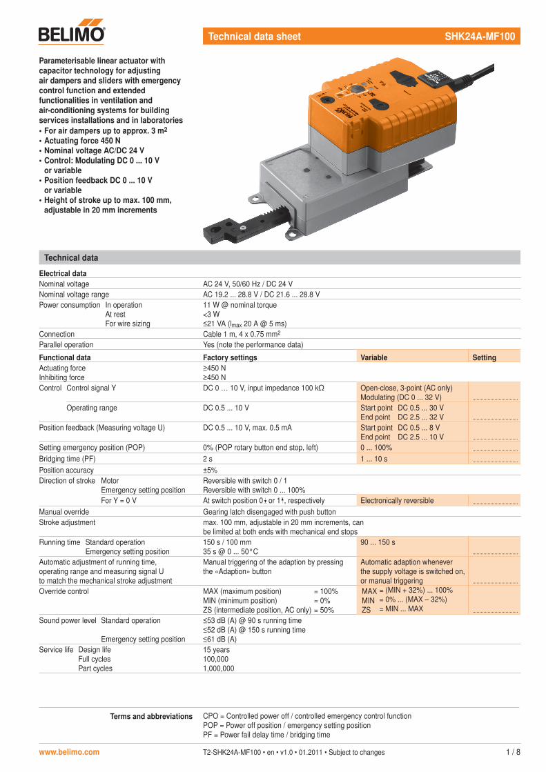
Parameterisable linear actuator with capacitor technology for adjusting air dampers and sliders with emergency control function and extended functionalities in ventilation and air-conditioning systems for building services installations and in laboratories• For air dampers up to approx. 3 m2
• Actuating force 450 N• Nominal voltage AC/DC 24 V• Control: Modulating DC 0 ... 10 V
or variable• Position feedback DC 0 ... 10 V
or variable• Height of stroke up to max. 100 mm,
adjustable in 20 mm increments
Terms and abbreviations CPO = Controlled power off / controlled emergency control functionPOP = Power off position / emergency setting positionPF = Power fail delay time / bridging time
Technical data
Electrical dataNominal voltage AC 24 V, 50/60 Hz / DC 24 VNominal voltage range AC 19.2 ... 28.8 V / DC 21.6 ... 28.8 VPower consumption In operation
At restFor wire sizing
11 W @ nominal torque<3 W≤21 VA (lmax 20 A @ 5 ms)
Connection Cable 1 m, 4 x 0.75 mm2
Parallel operation Yes (note the performance data)
Functional data Factory settings Variable SettingActuating forceInhibiting force
≥450 N≥450 N
Control Control signal Y DC 0 … 10 V, input impedance 100 k Open-close, 3-point (AC only)Modulating (DC 0 ... 32 V) .................................
Operating range DC 0.5 ... 10 V Start pointEnd point
DC 0.5 ... 30 VDC 2.5 ... 32 V .................................
Position feedback (Measuring voltage U) DC 0.5 ... 10 V, max. 0.5 mA Start pointEnd point
DC 0.5 ... 8 VDC 2.5 ... 10 V .................................
Setting emergency position (POP) 0% (POP rotary button end stop, left) 0 ... 100% .................................
Bridging time (PF) 2 s 1 ... 10 s .................................
Position accuracy ±5%Direction of stroke Motor
Emergency setting positionReversible with switch 0 / 1Reversible with switch 0 ... 100%
For Y = 0 V At switch position 0 or 1 , respectively Electronically reversible .................................
Manual override Gearing latch disengaged with push buttonStroke adjustment max. 100 mm, adjustable in 20 mm increments, can
be limited at both ends with mechanical end stopsRunning time Standard operation
Emergency setting position150 s / 100 mm35 s @ 0 ... 50°C
90 ... 150 s.................................
Automatic adjustment of running time, operating range and measuring signal U to match the mechanical stroke adjustment
Manual triggering of the adaption by pressing the «Adaption» button
Automatic adaption whenever the supply voltage is switched on, or manual triggering .................................
Override control MAX (maximum position)MIN (minimum position)ZS (intermediate position, AC only)
= 100%= 0%= 50%
MAXMINZS
= (MIN + 32%) ... 100%= 0% ... (MAX – 32%)= MIN ... MAX .................................
Sound power level Standard operation
Emergency setting position
≤53 dB (A) @ 90 s running time≤52 dB (A) @ 150 s running time≤61 dB (A)
Service life Design lifeFull cyclesPart cycles
15 years100,0001,000,000

SHK24A-MF100 Parameterisable linear actuator with capacitor technology, AC/DC 24 V, 450 N
2 / 8 T2-SHK24A-MF100 • en • v1.0 • 01.2011 • Subject to changes www.belimo.com
Safety notes
!• The actuator is not allowed to be used outside the specified field of application, especially in
aircraft or in any other airborne means of transport.• It may only be installed by suitably trained personnel. Any legal regulations or regulations
issued by authorities must be observed during installation.• The device may only be opened at the manufacturer's site. It does not contain any parts that
can be replaced or repaired by the user.• The cable must not be removed from the device.• The rotary supports and coupling pieces available as accessories must always be used if
lateral forces are likely. In addition, the actuator must not be tightly bolted to the application. It must remain movable via the rotary support (refer to «Assembly notes»).
• If a rotary support and/or coupling piece is used, then actuating force losses are to be expected.
• If the linear actuator is exposed to severely contaminated ambient air, appropriate precautions must be taken on the system side. Excessive deposits of dust, soot etc. can prevent the gear rod from being extended and retracted correctly.
• If not installed horizontally, the gear disengagement push button may only be actuated when there is no pressure on the gear rod.
• To calculate the actuating force required for air dampers and sliders, the specifications supplied by the damper manufacturers concerning the surface, cross-section, design, installation site and the air flow conditions must be observed.
• Self adaptation is necessary when the system is commissioned or whenever the stroke limiting is adjusted (press the adaptation push button).
• The device contains electrical and electronic components and is not allowed to be disposed of as household refuse. All locally valid regulations and requirements must be observed.
Technical data (continued)
SafetyProtection class III Safety extra-low voltage
UL Class 2 SupplyDegree of protection IP54
NEMA 2, UL Enclosure Type 2EMC CE according to 2004/108/ECCertification Certified to IEC/EN 60730-1 and IEC/EN 60730-2-14
cULus according to UL 60730-1A and UL 60730-2-14and CAN/CSA E60730-1:02
Mode of operation Type 1.AARated impulse voltage 0.8 kVControl pollution degree 3Ambient temperature –30 ... +50°CNon-operating temperature –40 ... +80°CAmbient humidity 95% r.h., non-condensatingMaintenance Maintenance-free
Dimensions / WeightDimensions See «Dimensions» on page 8Weight Approx. 1.6 kg
SHK24A-MF100 Parameterisable linear actuator with capacitor technology, AC/DC 24 V, 450 N
www.belimo.com T2-SHK24A-MF100 • en • v1.0 • 01.2011 • Subject to changes 3 / 8
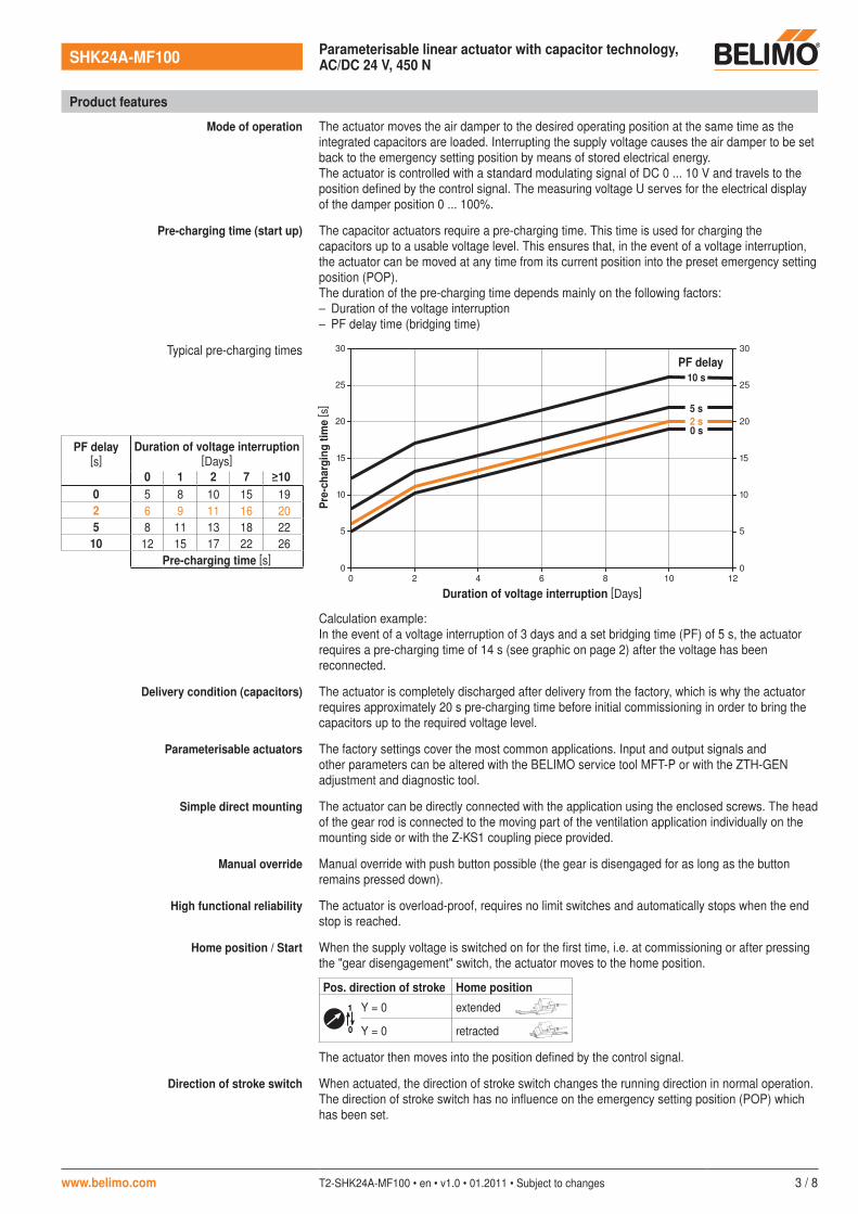
Calculation example:In the event of a voltage interruption of 3 days and a set bridging time (PF) of 5 s, the actuator requires a pre-charging time of 14 s (see graphic on page 2) after the voltage has been reconnected.
Delivery condition (capacitors) The actuator is completely discharged after delivery from the factory, which is why the actuator requires approximately 20 s pre-charging time before initial commissioning in order to bring the capacitors up to the required voltage level.
Parameterisable actuators The factory settings cover the most common applications. Input and output signals and other parameters can be altered with the BELIMO service tool MFT-P or with the ZTH-GEN adjustment and diagnostic tool.
Simple direct mounting The actuator can be directly connected with the application using the enclosed screws. The head of the gear rod is connected to the moving part of the ventilation application individually on the mounting side or with the Z-KS1 coupling piece provided.
Manual override Manual override with push button possible (the gear is disengaged for as long as the button remains pressed down).
High functional reliability The actuator is overload-proof, requires no limit switches and automatically stops when the end stop is reached.
Home position / Start When the supply voltage is switched on for the first time, i.e. at commissioning or after pressing the "gear disengagement" switch, the actuator moves to the home position.
Pos. direction of stroke Home position
Y = 0 extended
Y = 0 retracted0
1
The actuator then moves into the position defined by the control signal.
Direction of stroke switch When actuated, the direction of stroke switch changes the running direction in normal operation. The direction of stroke switch has no influence on the emergency setting position (POP) which has been set.
Product features
Mode of operation The actuator moves the air damper to the desired operating position at the same time as the integrated capacitors are loaded. Interrupting the supply voltage causes the air damper to be set back to the emergency setting position by means of stored electrical energy.The actuator is controlled with a standard modulating signal of DC 0 ... 10 V and travels to the position defined by the control signal. The measuring voltage U serves for the electrical display of the damper position 0 ... 100%.
Pre-charging time (start up) The capacitor actuators require a pre-charging time. This time is used for charging the capacitors up to a usable voltage level. This ensures that, in the event of a voltage interruption, the actuator can be moved at any time from its current position into the preset emergency setting position (POP).The duration of the pre-charging time depends mainly on the following factors:– Duration of the voltage interruption– PF delay time (bridging time)
Typical pre-charging times
0
0
5
10
15
20
25
30
2 4 6 8 10 12
0 s
5 s2 s
10 s
0
5
10
15
20
25
30
Pre-
char
ging
tim
e [ s
]
Duration of voltage interruption [Days]
PF delay
PF delay[s]
Duration of voltage interruption[Days]
0 1 2 7 ≥100 5 8 10 15 192 6 9 11 16 205 8 11 13 18 22
10 12 15 17 22 26Pre-charging time [s]
SHK24A-MF100 Parameterisable linear actuator with capacitor technology, AC/DC 24 V, 450 N
4 / 8 T2-SHK24A-MF100 • en • v1.0 • 01.2011 • Subject to changes www.belimo.com
Product features (continued)
Emergency setting position (POP) rotary button
The «Emergency setting position» rotary button can be used to adjust the desired emergency setting position (POP) between 0 and 100% in 10% increments.The rotary button is in reference only to the adapted stroke range between 30 and 100 mm. No set Min or Max values are observed.In the event of a voltage interruption, the actuator will move into the selected emergency setting position, taking into account the bridging time.
Settings The rotary button must be set to the «Tool» position for retroactive settings of the emergency setting position with the BELIMO service tool MFT-P. Once the rotary button is set back to the range 0 … 100%, the manually set value will have positioning authority
Bridging time (PF) Voltage interruptions can be bridged up to a maximum of 10 s.In the event of a voltage interruption, the actuator will remain stationary in accordance with the set bridging time. If the voltage interruption is greater than the set bridging time, then the actuator will move into the selected emergency setting position (POP).The bridging time set ex-works is 2 s. This can be modified at the site of operations with the BELIMO service tool MFT-P or with the ZTH-GEN adjustment and diagnostic device.
Settings The rotary button must not be set to the «Tool» position!Only the values need to be entered for retroactive adjustments of the bridging time with the BELIMO service tool MFT-P or with the ZTH-GEN adjustment and diagnostic device.
Accessories
Description Data sheet
Electrical accessories BELIMO service tool MFT-PZTH-GEN adjustment and diagnostic devicePositioner SGA24, SGE24 and SGF24 T2 - SG..24Digital position indicator ZAD24 T2 - ZAD24Room temperature controller CR24.. S4 - CR24-..
Mechanical accessories Rotary support to compensate lateral forces Z-DS1 T2 - Z-SH..A..Coupling piece Z-KS1 T2 - Z-SH..A..End stop set Z-AS1 T2 - Z-SH..A..
Electrical installation
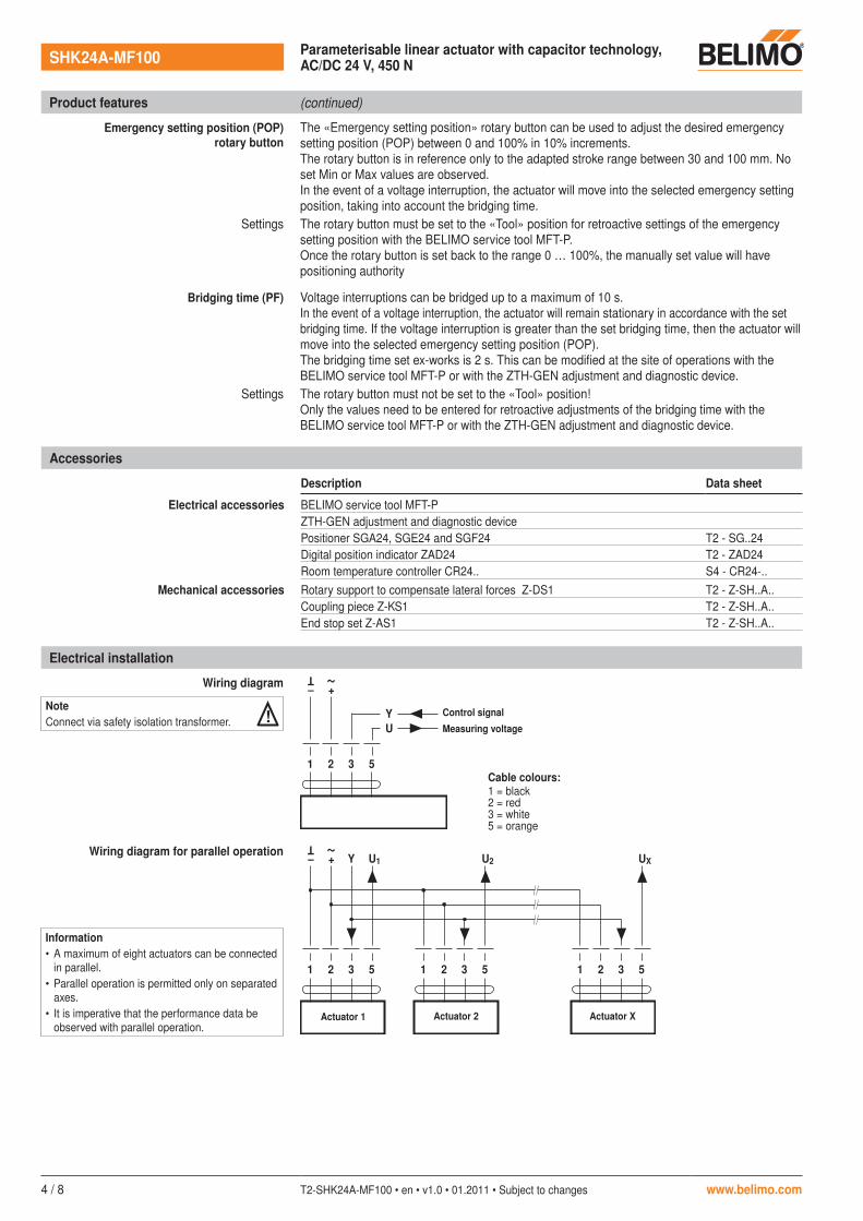
Wiring diagram
Y U
1 32 5
– +
T ~
Cable colours:1 = black2 = red3 = white5 = orange
Wiring diagram for parallel operation
1 32 5
– +
T ~
Y U1
1 32 5
U2
1 32 5
UX
NoteConnect via safety isolation transformer. ! Control signal
Measuring voltage
Actuator 1 Actuator 2 Actuator X
Information• A maximum of eight actuators can be connected
in parallel.• Parallel operation is permitted only on separated
axes.• It is imperative that the performance data be
observed with parallel operation.

SHK24A-MF100 Parameterisable linear actuator with capacitor technology, AC/DC 24 V, 450 N
www.belimo.com T2-SHK24A-MF100 • en • v1.0 • 01.2011 • Subject to changes 5 / 8
Electrical installation (continued)
Cable lengths
Y U
1 32 5
T ~
A
C
L1
L2
Ltot
A = ActuatorC = Control unitL1 = Belimo connecting cable, 1 m (4 x 0.75 mm2)L2 = Customer cableLtot = Maximum cable length
Cross-sectionL2T
/
~
Max. cable lengthLtot = L1 + L2
Example for DC
AC DC0.75 mm2 ≤40 m ≤20 m 1 m (L1) + 19 m (L2)1.00 mm2 ≤50 m ≤30 m 1 m (L1) + 29 m (L2)1.50 mm2 ≤80 m ≤45 m 1 m (L1) + 44 m (L2)2.50 mm2 ≤130 m ≤80 m 1 m (L1) + 79 m (L2)
NoteThere are no special restrictions on installation if the supply and data cable are routed separately.
LN
Y U
T
1 32 5A
CAC 24 V
AC 230 V
L1
A = ActuatorC = Control unitL1 = Belimo connecting cable, 1 m (4 x 0.75 mm2)
NoteWhen several actuators are connected in parallel, the maximum cable length must be divided by the number of actuators.
Functions with basic values
Override control with AC 24 V with relay contacts
a
1 2 3 5
b
UY
c
~T
Functions a b c
0%
ZS 50%(intermediate position)
100%
Control mode in accordance with Y
Remote control 0 ... 100% Minimum limit
1 2 3 5
UY
SGA24SGF24SGE244
Y Z21 3
T ~
~T
1 2 3 5
UY
SGA24SGF24SGE244
Y Z21 3
T ~
~T
100 0
Y [V]
10
min
0 [%]
Y (DC 0 ... 10 V)From controller
e.g. 1N 4007
Positioner Positioner
Y (DC 0 ... 10 V)From controller

SHK24A-MF100 Parameterisable linear actuator with capacitor technology, AC/DC 24 V, 450 N
6 / 8 T2-SHK24A-MF100 • en • v1.0 • 01.2011 • Subject to changes www.belimo.com
Functions for actuators with specific parameters
Override control and limiting with AC 24 V with relay contacts
Override control and limiting with AC 24 V with rotary switchT ~
a b c d
U
T ~
Y
e
51 2 3
Functions a b c d e
CLOSED
MIN
ZS(intermediate position)
MAX
OPEN
Control mode in accordance with Y
T ~
51 2 3
U
T ~
Y
3-point control Open-close control
U
T ~
U
T ~
Y
a b
51 2 3
U
T ~
+
U
T ~
Y
51 2 3
–
+–
Y (DC 0 ... 10 V)From controller
e.g. 1N 4007
Y (DC 0 ... 10 V)From controller
e.g. 1N 4007
e.g. 1N 4007
CLO
SED
MIN
ZS MA
XO
PEN
Functions with basic values (continued)
Control with 4 ... 20 mA via external resistance
1 2 3 5
U DC 2 ... 10 V
UY
(+)(–) 4 ... 20 mA
+
~
–
T
500 Ω
Position indication Functional check
1 2 3 5
ZAD24
421 3
~T
+ –
UY
1 2 3 5
UY
+
~
–
T
Procedure• Apply 24 V to connection 1 and 2• Disconnect connection 3:
– for stroke direction 0: Actuator moves in direction
– for stroke direction 1: Actuator moves in direction
• Short circuit connections 2 and 3:– Actuator runs in the opposite direction
Adapting the direction of rotation
The 500 -resistor converts the 4 ... 20 mA current signal to a voltage signal DC 2 ... 10 V.Operating range set to DC 2 ... 10 V.

SHK24A-MF100 Parameterisable linear actuator with capacitor technology, AC/DC 24 V, 450 N
www.belimo.com T2-SHK24A-MF100 • en • v1.0 • 01.2011 • Subject to changes 7 / 8
Setting the POP Power Off position
10
0.1
0.5
0.9
TOOL
10
0.1
0.5
0.9
TOOL
10
0.1
0.5
0.9
TOOL
10
0.1
0.5
0.9
TOOL
POP %
0...100
POP >
PC-Tool
ZTH-GEN
Status
10
0.1
0.5
1
0
0.9
TOOL
PowerAdaption
POP
SHK24A-MF100
Indicators and operating elements
Status
10
0.1
0.5
1
0
0.9
TOOL
PowerAdaption
POP
SHK24A-MF100 1 Direction of stroke switch
2 Cover, POP button
3 POP button
4 Scale for manual adjustment
5 Position for adjustment with tool
6 Tool socket
7 Disengagement button
LED displaysMeaning / function8 yellow 9 green
Off Illuminated Operation OK / without fault Illuminated Off Fault
Off Off Not in operationIlluminated Illuminated Adaptation procedure running
Blinking Illuminated Communication with programming tool
9 Press button: Triggers stroke adaption, followed by standard operation
6
7
1
2
34
895

SHK24A-MF100 Parameterisable linear actuator with capacitor technology, AC/DC 24 V, 450 N
8 / 8 T2-SHK24A-MF100 • en • v1.0 • 01.2011 • Subject to changes www.belimo.com
Assembly notes
Application without transverse forces The linear actuator is screwed directly to the housing at three points. Afterwards, the head of the gear rod is fastened to the moving part of the ventilation application (e.g. damper or slider).
Application with transverse forces The coupling piece with the internal thread (Z-KS1) is connected to the head of the gear rod.The rotary support (Z-DS1) is screwed to the ventilation application.Afterwards, the linear actuator is screwed to the previously mounted rotary support with the enclosed screw. Afterwards, the coupling piece, which is mounted to the head of the gear rod, is attached to the moving part of the ventilation application (e.g. damper or slider).The transverse forces can be compensated for to a certain limit with the rotary support and/or coupling piece. The maximum permissible swivel angle of the rotary support and coupling piece is 10° , laterally and upwards.
Stroke limitation If the stroke limitations are used on the gear rod, the mechanical working range can be exploited from an extension length of 20 mm.
Dimensions [mm]
Dimensional drawings
141
94
36
234100
81 99
190 41
CautionIf a rotary support and/or coupling piece is used, losses in the actuation force losses are to be expected.
!

LHK24A(..)/SHK24A(..)
www.belimo.com M2-LHK24A(..)/SHK24A(..) • v1.1 • 05.2011 1 / 2
7119
7-00
001.
C
±10°
3 x
1A
B
Ømax.8mm
2
20mm
20mm
2mm
3
4.5
Z-DS1
M8Z-KS1 (SHK..)Z-KS2 (LHK..)
1
Z-DS1
M8
5.5
Z-KS1(SHK..)Z-KS2(LHK..)
2
Z-DS1
20mm
20mm
2mm
Z-KS1 (SHK..)Z-KS2 (LHK..)
3

LHK24A(..)/SHK24A(..)
2 / 2 M2-LHK24A(..)/SHK24A(..) • v1.1 • 05.2011 www.belimo.com
AC24V/DC24V
1 2
–+
T ~
1 2
–+
T ~
3 1 2
T ~
3 4
LHK24AXSHK24AX
LHK24A-1SHK24A-1
LHK24AX-3SHK24AX-3
AC24V/DC24V
1 32 5
–+
T ~
Y DC0...10VU DC2...10V
1 32 5
–+
T ~
Y DC0...10VU DC0...10V
LHK24A-SRSHK24A-SR
LHK24A-SZ LHK24A-MFSHK24A-SZ SHK24A-MF
YU
1 32 5
–
T ~
+
DC0…10VMP
LHK24A-MPSHK24A-MP