technical description of heart - expert help with your ... · 3 technical description of heart...
TRANSCRIPT

HUNT ENGINEERING Chestnut Court, Burton Row,
Brent Knoll, Somerset, TA9 4BP, UK Tel: (+44) (0)1278 760188, Fax: (+44) (0)1278 760199,
Email: sales@hunteng. co.uk http://www.hunteng.co.uk http://www.hunt-dsp.com
Technical description of
HEART
Document version 1.0
P.Warnes 7/1/02
2 Technical description of HEART
COPYRIGHT This documentation and the product it is supplied with are Copyright HUNT ENGINEERING 2002. All rights reserved. HUNT ENGINEERING maintains a policy of continual product development and hence reserves the right to change product specification without prior warning.
WARRANTIES LIABILITY and INDEMNITIES HUNT ENGINEERING warrants the hardware to be free from defects in the material and workmanship for 12 months from the date of purchase. Product returned under the terms of the warranty must be returned carriage paid to the main offices of HUNT ENGINEERING situated at BRENT KNOLL Somerset UK, the product will be repaired or replaced at the discretion of HUNT ENGINEERING.
Exclusions - If HUNT ENGINEERING decides that there is any evidence of electrical or mechanical abuse to the hardware, then the customer shall have no recourse to HUNT ENGINEERING or its agents. In such circumstances HUNT ENGINEERING may at its discretion offer to repair the hardware and charge for that repair.
Limitations of Liability - HUNT ENGINEERING makes no warranty as to the fitness of the product for any particular purpose. In no event shall HUNT ENGINEERING’S liability related to the product exceed the purchase fee actually paid by you for the product. Neither HUNT ENGINEERING nor its suppliers shall in any event be liable for any indirect, consequential or financial damages caused by the delivery, use or performance of this product.
Because some states do not allow the exclusion or limitation of incidental or consequential damages or limitation on how long an implied warranty lasts, the above limitations may not apply to you.
TECHNICAL SUPPORT Technical support for HUNT ENGINEERING products should first be obtained from the comprehensive Support section www.hunteng.co.uk/support/index.htm on the HUNT ENGINEERING web site. This includes FAQs, latest product, software and documentation updates etc. Or contact your local supplier - if you are unsure of details please refer to www.hunteng.co.uk for the list of current re-sellers.
HUNT ENGINEERING technical support can be contacted by emailing [email protected], calling the direct support telephone number +44 (0)1278 760775, or by calling the general number +44 (0)1278 760188 and choosing the technical support option.
3 Technical description of HEART
TABLE OF CONTENTS WHAT IS THIS DOCUMENT FOR? ...........................................................................4
WHAT IS HEART?.........................................................................................................5 WHAT IS DIGITAL SIGNAL PROCESSING? .................................................................................................. 5 WHAT IS REAL TIME? ............................................................................................................................... 5
WHY DO WE NEED HEART?......................................................................................6
WHAT DOES IT ALLOW US TO DO?........................................................................7
IS IT A STANDARD?......................................................................................................8
NODAL SYSTEMS..........................................................................................................9
HEART IMPLEMENTATION ....................................................................................10 ONE HEART “NODE ACCESS POINT” ...................................................................................................... 10 TIME SLOTS ............................................................................................................................................. 12 MAKING A CONNECTION ......................................................................................................................... 13 USING MULTIPLE TIME SLOTS FOR A CONNECTION.................................................................................. 14 MULTIPLE CONNECTIONS BETWEEN THE SAME NODES ............................................................................ 15 DEFAULT ROUTING JUMPERS................................................................................................................... 16 RE-USING A TIME SLOT............................................................................................................................ 17 MULTI-CAST ........................................................................................................................................... 18 NON BLOCKING MODES ........................................................................................................................... 19 FLUSHING FIFOS .................................................................................................................................... 19 SMALL PACKETS AND DSPS .................................................................................................................... 20 RUNNING OUT OF RESOURCES ................................................................................................................. 21 RECONFIGURING SYSTEMS WHILE RUNNING............................................................................................ 21

4 Technical description of HEART
What is this document for?
Users of HUNT ENGINEERING systems need to know “how to use the system”. The instructions for that are contained in the multimedia presentations, and the user manuals for the individual products. A user of the system does not need to understand the underlying technology used as long as they understand how to make it do what they want. HEART is a piece of core technology for HUNT ENGINEERING HERON systems. It provides many features to the system programmer (user). While the way that it achieves this is not required knowledge, many users will be interested to know “how does it work?”
In order to clarify the divide between “how to use” the system, and “how the system works” we have split the information into separate documents. This “technology” document provides answers to “how does it work?” This document describes the architecture as it can be applied to many different products, the answers to “how do I use it?” can be found in the individual user manuals for each product that implements HEART.
No user of a HERON/HEART system needs to read this document, it is not necessary to understand anything in it to be able to use the system. This document is merely provided for the curious.
5 Technical description of HEART
What is HEART?
HEART is an acronym for “Hunt Engineering Architecture using Ring Technology”. It is an architectural concept that has been developed by us specifically for “Digital Signal Processing” systems that need to operate in “Real Time”.
What is Digital Signal Processing?
DSP is the processing of real world signals in the digital domain. The advantages of using digital techniques are that the processing of digital data is repeatable (unaffected by temperature, humidity, ageing etc) and re-programmable (same hardware can support multiple algorithms, system enhancements etc).
HERON modules are designed for use in such systems, providing processing nodes (C6000, FPGA etc), and real world interfaces (A/D, D/A, digital interfaces, video interfaces etc).
What is Real Time?
“Real time” is often misinterpreted as “fast”. While Real Time systems often need to be fast as well, this is not the meaning of real time. Real Time means that the system must respond to the outside world in a given time -- every time. That time might be once per day, or several Million times per second, both are real time.
In order to respond in a given time, the time that the processing takes must be known. That is the minimum and maximum time – it is not acceptable if the processing is fast enough “most” of the time, the worst case scenario must be accounted for, i.e. if event A occurs while event B is being processed and event C occurs etc.
Having enough processing power to complete the processing “on time” is not enough either. The data must be gathered and output “on time” also, i.e. the communications in the system must also be “real time”.

6 Technical description of HEART
Why do we need HEART?
A HERON system is designed for real time operation, using connections based upon FIFOs that guarantee no arbitration delay and the (maximum) bandwidth available.
HEART is an architecture that is designed to provide a software configurable set of connections that then guarantee Real Time communications between the modules in the system.
Additionally it provides useful features that are commonly requested for such systems.

7 Technical description of HEART
What does it allow us to do?
Anyone who has used a telephone knows that a critical system that must operate in real time would never consider placing a telephone call in order to transmit its data in real time. The dialling delays might be acceptable (they can certainly be characterised) the bandwidth of the line might be enough for your system needs. What is unacceptable is the fact that the line might be busy, or go unanswered. This means that when the call is initiated you cannot guarantee how long it will take to complete your communication.
This is one of the problems that HEART addresses. On the one hand we need an architecture that can be re-configured to meet the needs of different systems, or even the changing needs of a system. On the other hand we cannot tolerate any connection, or arbitration delays that can destroy the real time nature of your system.
The architecture is defined not only for communications between nodes on a carrier board but also for communications between boards in a system.
The architecture allows us to provide a number of novel features that our experience over more than ten years in the business shows us can be useful.

8 Technical description of HEART
Is it a standard?
HEART is not a standard, and will never be pushed as a standard. It forms a common thread through HUNT ENGINEERING products, but is essentially a proprietary product. This document and others may be enough information to allow someone to “clone” HEART, but it is not our intention to support users or competitors to produce products based on it. We may entertain supporting users that make a good case for developing their own HEART products, but that will almost certainly be on a royalty paying license basis. We reserve the right to decline any such requests.
We do support users who wish to develop their own HERON modules and carriers though, and the specification for the module can be found on the HUNT ENGINEERING CD and web site.
HEART is not necessary in a HERON system – it merely adds significant features to such a system.
9 Technical description of HEART
Nodal systems
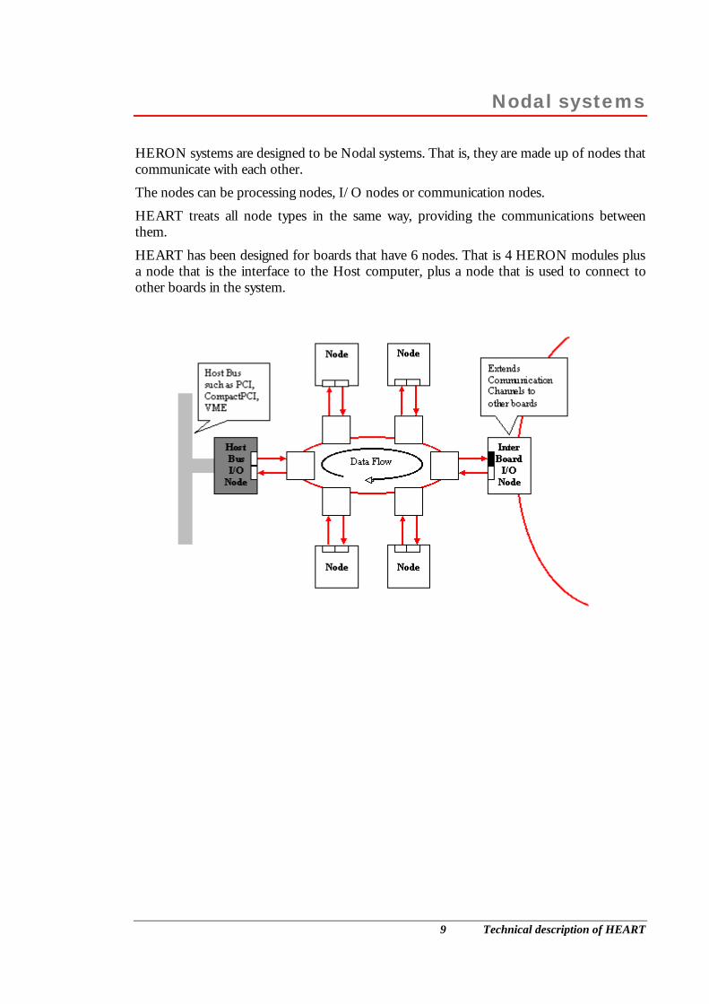
HERON systems are designed to be Nodal systems. That is, they are made up of nodes that communicate with each other.
The nodes can be processing nodes, I/O nodes or communication nodes.
HEART treats all node types in the same way, providing the communications between them.
HEART has been designed for boards that have 6 nodes. That is 4 HERON modules plus a node that is the interface to the Host computer, plus a node that is used to connect to other boards in the system.

10 Technical description of HEART
HEART Implementation
HEART is implemented in hardware (realised in FPGAs). Each of the six “Node access points” are identical, and connected in a ring.
One HEART “node access point”
Each node is connected through the HERON interface. That interface defines a 32 bit input path, and a separate 32 bit output path. Each of these paths is like a group of synchronous FIFOS, using a common data path and clock, but separate control signals.
The HEART device on the module carrier board is also split into a read side and a write side. Each provides 6 separate FIFOs that can be accessed at the “far” end by the HERON module.
Data is passed from the Read side to the write side, through two registers.
When the six nodes are connected together to form a ring, data is passed from one node to
READ Interface with common datapath, and clock, but six separateoutput enables, read enables andstatus flags.
WRITE Interface with commondata path, and clock, but sixseparate write enables and statusflags.
Implemented on module
Implemented on carrier
Regi
ster
Regi
ster
Regi
ster
Regi
ster
I/P
FIFO
0
I/P
FIFO
1
I/P
FIFO
2
I/P
FIFO
3
I/P
FIFO
4
I/P
FIFO
5
O/P
FIF
O 1
O
/P F
IFO
2
O/P
FIF
O 3
O
/P F
IFO
4
O/P
FIF
O 5
O/P
FIF
O 0
11 Technical description of HEART
another through a similar pair of registers. As the registers are clocked, the data will pass from node to node, and eventually back to the same register again. This means data can be sent from a node to itself and that data will travel around the whole ring.
2002
The “Ring” is formed out of a 32 bit data path and some control signals. The “Ring” of registers is clocked at 100Mhz meaning that 400Million bytes/second pass between each node. The use of million rather than mega is deliberate. 1Million bytes is not the same as 1 Mbyte!
Future
It is possible that future HEART implementations could increase the bandwidth by making the connection wider, or be clocked faster. The point is that the architecture does not impose the limit of bandwidth, the currently available commercial logic parts that result in an acceptable component cost is where the limit is. Of course the electronics industry will continue to produce faster/cheaper and denser logic parts.
12 Technical description of HEART
Time slots
So how can we use this ring for many connections in our system?
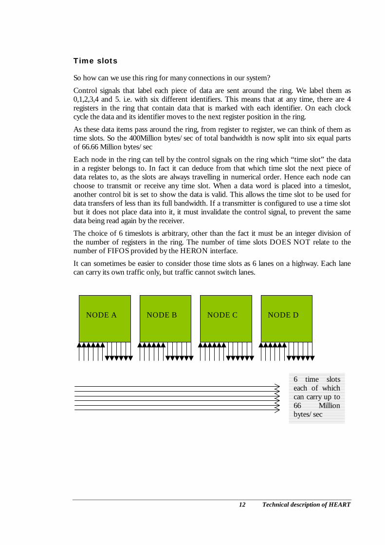
Control signals that label each piece of data are sent around the ring. We label them as 0,1,2,3,4 and 5. i.e. with six different identifiers. This means that at any time, there are 4 registers in the ring that contain data that is marked with each identifier. On each clock cycle the data and its identifier moves to the next register position in the ring.
As these data items pass around the ring, from register to register, we can think of them as time slots. So the 400Million bytes/sec of total bandwidth is now split into six equal parts of 66.66 Million bytes/sec
Each node in the ring can tell by the control signals on the ring which “time slot” the data in a register belongs to. In fact it can deduce from that which time slot the next piece of data relates to, as the slots are always travelling in numerical order. Hence each node can choose to transmit or receive any time slot. When a data word is placed into a timeslot, another control bit is set to show the data is valid. This allows the time slot to be used for data transfers of less than its full bandwidth. If a transmitter is configured to use a time slot but it does not place data into it, it must invalidate the control signal, to prevent the same data being read again by the receiver.
The choice of 6 timeslots is arbitrary, other than the fact it must be an integer division of the number of registers in the ring. The number of time slots DOES NOT relate to the number of FIFOS provided by the HERON interface.
It can sometimes be easier to consider those time slots as 6 lanes on a highway. Each lane can carry its own traffic only, but traffic cannot switch lanes.
NODE A
NODE B
NODE C
NODE D
6 time slots each of which can carry up to 66 Million bytes/sec

13 Technical description of HEART
Making a connection
So how can you use the timeslots to send and receive data?
At system reset, each Node Access Point has six FIFOs in each direction, which are not connected to HEART. In fact any connections that were made before the reset are disconnected by the reset.
To set up a connection in the system, the Node access point of the Transmitting module must “connect” the FIFO that will be used, to a time slot. Now data written into that FIFO by the node will be placed onto the ring, whenever a marker shows that the correct time slot is at this node. If the FIFO is empty when the time slot passes, no data will be placed onto the ring, and the control bit will be set to “invalid”. At this point there is no node set to receive the data, so it will simply travel around the ring until it reaches the transmitting node again. At that point it will be overwritten or invalidated (overwritten with an empty data item).
So now we must configure a receiver for the data. The Node Access point for the receiver needs the FIFO that it will use to be set to receive data from the correct time slot. Now whenever the correct time slot passes the receiving node, the data valid bit will be checked. If the data is valid, the data will be copied into the receiving node’s FIFO. If the data is not valid nothing will be done. Note that the data is not destroyed, or invalidated by the receiving node.
Now we have a connection made, where any data written into the transmitting FIFO, will appear in the receiver’s FIFO. Each Node can use the flags provided by its local FIFO to control when it can write or read data.
To ensure that data is not lost between the FIFOs, another control signal is used in the ring. This signal is used to signal backwards around the ring, when the receiving FIFO is approaching its full state. This signal is used to prevent the sending FIFO from placing any more data items onto the ring. There can still be several data items already on the ring, which will still be received by the receiving FIFO. This is possible because the control signal is not the Full flag of the receiving FIFO, but an almost full flag. The transmitting node does not pass the blocking signal on around the ring, so it is possible for the receiver to de-assert the signal when it is ready to accept data again.
NODE A
NODE B
NODE C
NODE D
One connection made between Nodes A and B

14 Technical description of HEART
Using Multiple time slots for a connection
The connection we have made in the section above uses a single timeslot. That means the maximum number of timeslots passing the node is equivalent to 66.6 Million bytes/sec. The transmitting and receiving nodes will each throttle the transfer to suit themselves, but the transfer cannot exceed the limit of the time slot.
If you want to achieve a higher transfer rate, you can allocate several timeslots to the transfer. You use the same single FIFO at each end of the transfer, but simply allocate multiple time slots for the connection between them. Then the nodes read and write their FIFOs in the same way and the HEART hardware will ensure that the data ordering is preserved.
Using multiple time slots for a connection should only be used when the system requires that bandwidth as it consumes system resources, and may make it harder to achieve the topology that you need.
NODE A
NODE B
NODE C
NODE D
One connection made between Nodes A and B using two timeslots “in parallel”

15 Technical description of HEART
Multiple connections between the same nodes
The use of one FIFO and several time slots is the way that you achieve a high bandwidth connection, but there is another way to connect several time slots between the same nodes.
That is to use more than one independent connection. In this case you make one virtual connection using one or more time slots, and then make a second connection with its own time slots.
In this case the nodes send and receive the data using different FIFO numbers, handling them as different communications. There is no synchronisation between the two connections.
This can be useful for a number of reasons. For example:-
Your nodes can assign priority to the different streams, and the high priority data can “overtake” the low priority data.
You can separate control flow from data, sending them over separate virtual connections.
NODE A
NODE B
NODE C
NODE D
Two separate connections made between Nodes A and B
16 Technical description of HEART
Default routing jumpers
HERON modules have default routing jumpers that perform a carrier specific function. This is intended to be used for setting connections without having to program them.
In the case of a HEART board, these Default Routing Jumpers are used to assign time slots to FIFO 0. They cannot affect the other FIFOs.
The jumpers are numbered from 0 to 5, and each corresponds to a time slot number. Fitting a jumper to a particular slot means that immediately following reset, that time slot number will be connected to FIFO 0. If you fit multiple jumpers then multiple time slots will be connected.
The Default connection can be overridden by any software (over HSB) configurations.
In most HEART systems the topology will be set over HSB, so it will not be necessary to use the Default Routing Jumpers at all.
A simple system though could use the Default Routing jumpers to connect the system using FIFO 0’s without the need to configure the topology after that.

17 Technical description of HEART
Re-using a time slot
In the sections above we discussed making a connection between two nodes using one or more time slots. We noted that the receiving node did not destroy or invalidate the data as it passed. This means that the data in that time slot will continue around the ring until it is overwritten/invalidated by the original transmitting node.
However another node in the system can be configured to transmit into the same time slot. As long as this new transmitter is after the last receiver of the original connection, this is an acceptable use of the system. i.e. as long as two connections to not overlap on the ring, the same time slot can be used by the two connections.
In this case each transmitter simply overwrites or invalidates the data from the other transmitter, breaking the timeslot into two separate connections. The fact that each transmitting node does not pass on the blocking signal means that this is also split into separate sections. Thus each virtual connection can “block” its transmitter without affecting the other connections that use the same time slot.
The result of allowing re-use of slots in this way is to provide more system resources for making connections. The limit of 400Million bytes/sec is no longer system wide, but is now applied to each segment of the ring independently.
NODE A
NODE B
NODE C
NODE D
Two separate connections made between Nodes A and B, then Nodes B and D, re-using the same timeslot
18 Technical description of HEART
Multi-Cast
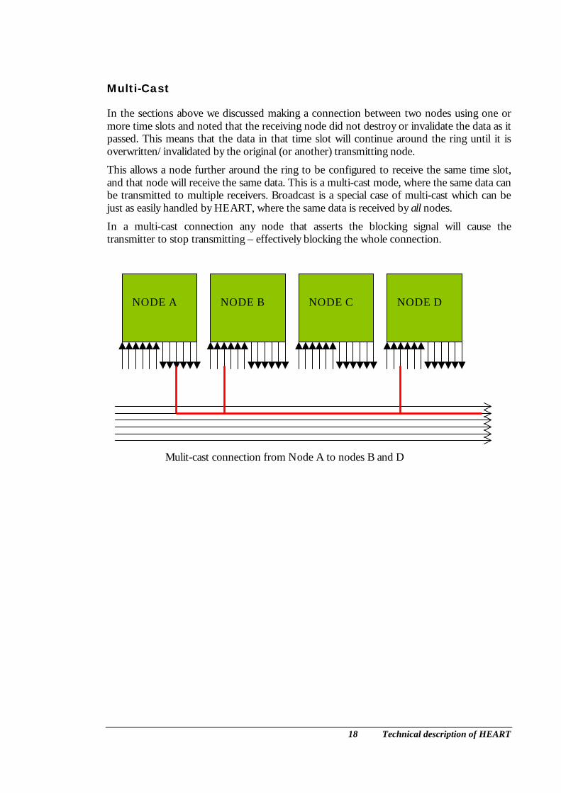
In the sections above we discussed making a connection between two nodes using one or more time slots and noted that the receiving node did not destroy or invalidate the data as it passed. This means that the data in that time slot will continue around the ring until it is overwritten/invalidated by the original (or another) transmitting node.
This allows a node further around the ring to be configured to receive the same time slot, and that node will receive the same data. This is a multi-cast mode, where the same data can be transmitted to multiple receivers. Broadcast is a special case of multi-cast which can be just as easily handled by HEART, where the same data is received by all nodes.
In a multi-cast connection any node that asserts the blocking signal will cause the transmitter to stop transmitting – effectively blocking the whole connection.
NODE A
NODE B
NODE C
NODE D
Mulit-cast connection from Node A to nodes B and D

19 Technical description of HEART
Non blocking modes
Some circumstances can be imagined where you would not want a connection to be “blocked” when the receiver FIFO is becoming full. The circumstances would be entirely dependent on the application. To handle this situation it is possible to configure a receiver as “non-blocking”. This means that if its FIFO is becoming nearly full the control signal that stops the transmitter will not be asserted.
This could be used (for example) when a multi-cast should not be stopped if one node is not ready to receive. In this case the non-blocking receiver may lose data from the stream, and the application program for that node must be designed to handle that situation.
Another example where it could be used is if an I/O module such as an A/D is the transmitter. Such I/O devices cannot be stopped and re-started as they are sampling real world signals. Using a non-blocking connection means that the real time A/D data continues to be placed onto the ring. If a receiver is not ready to receive for some time and then re-starts receiving, the only “stake” data in the system will be in its receive FIFO.
The non-blocking modes must only be chosen when it is desirable in the context of the system design, and if you are not sure it should not be chosen. For this reason the default connection type is “blocking”.
Flushing FIFOs
In some situations it can be desirable to “reset” a connection. That is to flush any data in the FIFOs.
One such situation arises from the A/D case discussed in the previous section. After some time where a receiver has not been reading, the receive FIFO (at least) will contain data that is of unknown timing. It can be useful to simply discard that data, so that processing can re-start on fresh (real time) data.
HEART devices implement a FIFO flush mode, using one of the UMI connections. By programming a register in the HEART device using HSB, you can make a FIFO be “reset” when one of the four UMI signals is asserted. Then a DSP or FPGA module can simply pulse the UMI signal each time it wants to “flush” the FIFO.
Using the UMI means that if it is desirable to flush both (or all) FIFOs in a connection, then those FIFOs can simply be programmed to be reset using the same UMI signal, and whenever the UMI is used all of the FIFOs are flushed at once.
20 Technical description of HEART
Small packets and DSPs
When hardware accesses a HERON FIFO, it will typically respond to the FIFO flag that is at the limit (i.e. the empty or full flags) to determine if data can be transferred. Because of the timing of FIFO flags it can be useful to also use the “almost” flags. Then the following logic can be used.
If not “almost” then transfer one data item per clock.
If “almost “ is asserted then check the “limit”, and transfer a single word as allowed. Recheck the flag before making each transfer.
Hardware can implement this quite efficiently, but a processor cannot. Usually a DMA will be used to make a transfer to or from the FIFO. There is an overhead associated with setting up the DMA, both in terms of processor instructions and hardware pre and post –amble. To minimise these effects it is normal to transfer as large a block of data as possible with each DMA.
In fact there is a trade off in choosing that block size. If you choose too small then there will be lots of small DMAs and the overheads will become significant. Transferring packets that are less than one block cannot use DMA, and must be transferred using less efficient access types. If you choose too large a block size, then the size below which transfers are inefficient gets raised. Then small packets will be slowed down.
HEART devices provide a FIFO flag to trigger a DMA block. To provide a good compromise the FLAG is used to indicate that a block of 64 words (32 bits each) can be transferred. However it may not be unusual to transfer a packet that is smaller than this.
To help with that problem, HEART devices provide a programmable “almost” flag. This flag is programmable between the limit flag and the block flag, i.e. they can be set to indicate any value between 2 and 63.
Then “special” functions on the processor can use that customised “almost” flag to trigger a smaller transfer. This is only useful if a particular connection will always use a small packet size that is constant. It is not intended that these flags be re-programmed between each transfer as that would be just as efficient as transferring the data using the limit flag.
The “almost” flags are not conventionally used by processor modules, and may be inaccessible to the processor (such as on the HERON4 module). For this reason HEART devices also allow a UMI pin to be driven by an almost flag. In that case the module can poll the UMI signal to determine if a block of the programmed size can be transferred.
These features can be used on C6000 modules by some of the advanced functions in HERON-API.

21 Technical description of HEART
Running out of resources
As in any real world system, there are finite resources available to you. The obvious ones like “do I have enough module slots for the number of modules I need?” should not be difficult to answer, but there is also a limit of bandwidth on each segment of the ring.
The ability to use multiple time slots to increase the bandwidth limit for a specific connection, and the ability to re-use time slots further around the ring help you to get the maximum use of the available bandwidth. However there will still be circumstances where there is not enough system bandwidth for what you want to do.
You can see if this is the case by making sketches like those above, but it is perhaps simpler to enter your required connectivity into your network file, and run the software tools. If there is not enough resources to implement what you have asked for an error message is issued.
Often placing the modules in a different order can resolve such conflicts.
The discovery of insufficient resources at the development stage of your system is important. Consider designing a similar system where the nodes are connected using an arbitrated bus (PCI for example). It could be true that the PCI limitation of 132Million bytes/sec is much higher than any of your communications will need. But how do you tell if that system will always run in real time? It could be that during the operation of your system several communications are necessary at the same instant. It is hard enough in that case to determine if the bandwidth of your system will be sufficient, and certainly one or more of the communications will be delayed while the bus is busy making another transfer.
Conversely if your HEART system can be successfully configured during your development, the resource availability will not change each time you run your system. The bandwidths available are guaranteed to be available.
This means it is preferable to learn of your limitations at design time than as the result of many difficult hours of debugging a “random” system failure in the field.
Reconfiguring systems while running
The design of HEART has been made using the assumption that your system connectivity is pre-configured before your application program starts to execute. If this assumption is correct then the system resources will be guaranteed, and the delivery of data by HEART can be relied upon.
However there is nothing in the design of HEART that stops you from reconfiguring connections while your system is running.
There are several issues that need to be taken care of by your system design if you are to attempt this. This means re-configuring of connections should not be attempted unless it is really necessary and you fully understand the consequences.
The fact that there is no arbitration means that reconfiguring a connection will not be “agreed” between nodes in the system. The action of sending the HSB messages to set a new connection will be applied by the hardware immediately. This means that you should be careful about any data that is being transmitted on the connection during the re-

22 Technical description of HEART
configuration.
If for example the previous connection is still carrying data when the connection is re-configured, some data may be lost. The node that was previously receiving the data may hang waiting for the completion of a “packet”, and the receiver of the new connection may receive some data that was not intended for it.
If you are to use re-configuration in your system, it is recommended that you stop transmitting data before making the re-configuration. Perhaps HSB messages can be used to achieve this, but it is up to your application program to handle the consequences.