technical glass products architectural specification · pdf filetechnical glass products ....
TRANSCRIPT

800.426.0279 | fireglass.com
Technical Glass Products Architectural Specification Manual

800.426.0279 | fireglass.com Architectural Specification Manual 2 R171019
FIREFRAMES® DESIGNER SERIES
The Fireframes® Designer Series frame system, incorporating precise roll-forming technology, provides a sleek, modern alternative to traditional hollow metal frames. Using narrow profiles, the Fireframes Designer Series frame system exceeds traditional fire-rated frame systems in aesthetics and performance. Available with fire ratings from 20 to 90 minutes, this modular system can incorporate fire doors and a wide range of fire-rated glazing materials with glass sizes surpassing traditional systems. For specifications, photographs and additional information contact:
© October 2017 Technical Glass Products. Pilkington Pyrostop is a registered trademark of Pilkington PLC. Technical Glass Products, Fireframes, Fireglass and One Source. Many Solutions. are registered trademarks of Technical Glass Products. This information is intended for general reference only.
Technical Glass Products 8107 Bracken Place SE Snoqualmie, WA 98065 Office: 800.426.0279 425.396.8200 Fax: 800.451.9857 425.396.8300 E-mail: [email protected] Web: fireglass.com

800.426.0279 | fireglass.com Architectural Specification Manual 3 R171019
Table of Contents
System Exploded View ..................................................................................................................................... 4 Material Key Chart ........................................................................................................................................... 5 General Information ........................................................................................................................................ 6
Features ....................................................................................................................................................................... 7
Listings ......................................................................................................................................................................... 7
Sizing Guidelines ........................................................................................................................................................8
Americans with Disability Act Standards on Fire Protection Doors.................................................................... 9
Conventional Wood or Hollow Metal Doors in Fireframes Designer Series Frames ...................................... 9
Fire-Rated Glazing Options ..................................................................................................................................... 10
Glazing Specifications ............................................................................................................................................... 11
Arched Top (Radius) Frames ................................................................................................................................... 12
How to Determine Door Handing ...........................................................................................................................13
Door Hardware Configurations and Hardware Options ..................................................................................... 14
Recommended Guidelines .............................................................................................................................. 15 Sample Elevations – Windows ........................................................................................................................ 17 Sample Section Details – Windows ................................................................................................................. 18 Sample Elevations – Single Doors .................................................................................................................. 21 Sample Elevations – Door Pairs ...................................................................................................................... 22 Sample Elevations – Wide Stile Doors ............................................................................................................ 23 Sample Section Details – Doors ..................................................................................................................... 24

800.426.0279 | fireglass.com Architectural Specification Manual 4 R171019
Figure 1 - System Exploded View
System Exploded View
13
12
6
8
2
4
7
1
8
13
10
9
5
9
ITEM DESCRIPTION
1 PROFILE, WALL JAMB "L"2 BEAD STUD3 PROFILE, DOOR JAMB "Z"4 PROFILE, INTERMEDIATE "T"5 SETTING BLOCK
ITEM DESCRIPTION
6 FIRE-RATED GLASS7 PROFILE, DOOR JAMB "L"8 8-32x1" FHMS BEAD LOCK SCREW9 GLAZING BEAD, STEEL GALVANIZED
10 GASKET, NEOPRENE DOOR STOP
ITEM DESCRIPTION
11 PROFILE, DOOR JAMB "T"12 PIVOT ASSEMBLY13 GLAZING TAPE
112
3

800.426.0279 | fireglass.com Architectural Specification Manual 5 R171019
Material Key Chart
Material Required Material NOT PROVIDED With Fireframes Designer Series
FINISH SEALANT Sealant installed into the interior and exterior perimeter cavity. Select color for sealant to match frame or as directed by project architect.
CAP SEAL REQUIRED on all exterior applications, use a continuous silicone sealant. Select color to match frame.
ANCHOR FASTENER As wall constructions vary widely in design, TGP does not provide perimeter fasteners (anchors). All frames are factory drilled to receive #12 flat head perimeter screws at approximately 18” on center.
FIRESAFING
Intumescent sealant or firmly packed mineral wool must be installed in a continuous fashion between frame assembly and wall construction, being interrupted only by the perimeter anchor shims. Sealant manufacturers such as Tremco, Pemko and many others supply intumescent sealants.
FLASHING Exterior sill flashing, if required, may be stainless steel, galvanized steel, or aluminum.
HEEL BEAD REQUIRED on all exterior applications: apply a continuous bead of silicone sealant at all horizontal to vertical intersections in the glazing pocket, and a heel bead along the sill and 4” vertically up each jamb. Sealant must be installed between the glass edge and frame profile.
GLAZING TAPE Single or double sided adhesive, closed cell PVC glazing tape of any common brand available from your local glazing supply house. Refer to Glazing Specifications for glazing tape sizes, and Glazing Installation Instructions.
SHIMS Perimeter shims at anchor locations are to be of hardwood (oak) or non-combustible (steel) materials. Plastic shims may not be used. TGP recommends a 3/8” (9.5 mm) caulk joint between frame and all wall conditions.
WALL CONDITION Rated wall construction by other trades. Material Fasteners Provided With Fireframes Designer Series
BEAD LOCK SCREW 8-32 X 1” Flat Head Screws. The glazing beads and frame are factory fabricated to receive lock screws. The screws are supplied with screw heads painted to match frames. Bead lock screws are not used on non-rated applications.
BEAD STUD Glazing beads snap onto factory installed, steel bead studs at approximately 12” on center. Material Components Provided With Fireframes Designer Series
SETTING BLOCKS 6 mm calcium silicate, or hardwood, setting blocks shipped loose for field installation. Refer to Glazing Installation Instructions.
FIRE-RATED GLAZING MATERIAL
Refer to the Fire-Rated Glazing Options and Specifications, and Glazing Installation Instructions.
FIRE-RATED GLAZING TAPE Fire-rated glazing tape for 90 minute Fireframes Designer Series assemblies only. Refer to Glazing Specifications section for glazing tape sizes, and Glazing Installation Instructions.
MECHANICAL JOINT CONNECTOR
In the event of a mechanically joined frame, this clip inserts into the receiving end of the frame to be joined and fastens with provided screws. (Not used with exterior applications).
GLAZING BEAD Snap-on glazing bead to hold glass in system. WEATHER SEAL Silicone gasket used on Fireframes Designer Series door meeting stiles. DOOR GASKET Neoprene door stop gasket used on Fireframes Designer Series doors.
Figure 2 - Material Key Chart
800.426.0279 | fireglass.com Architectural Specification Manual 6 R171019
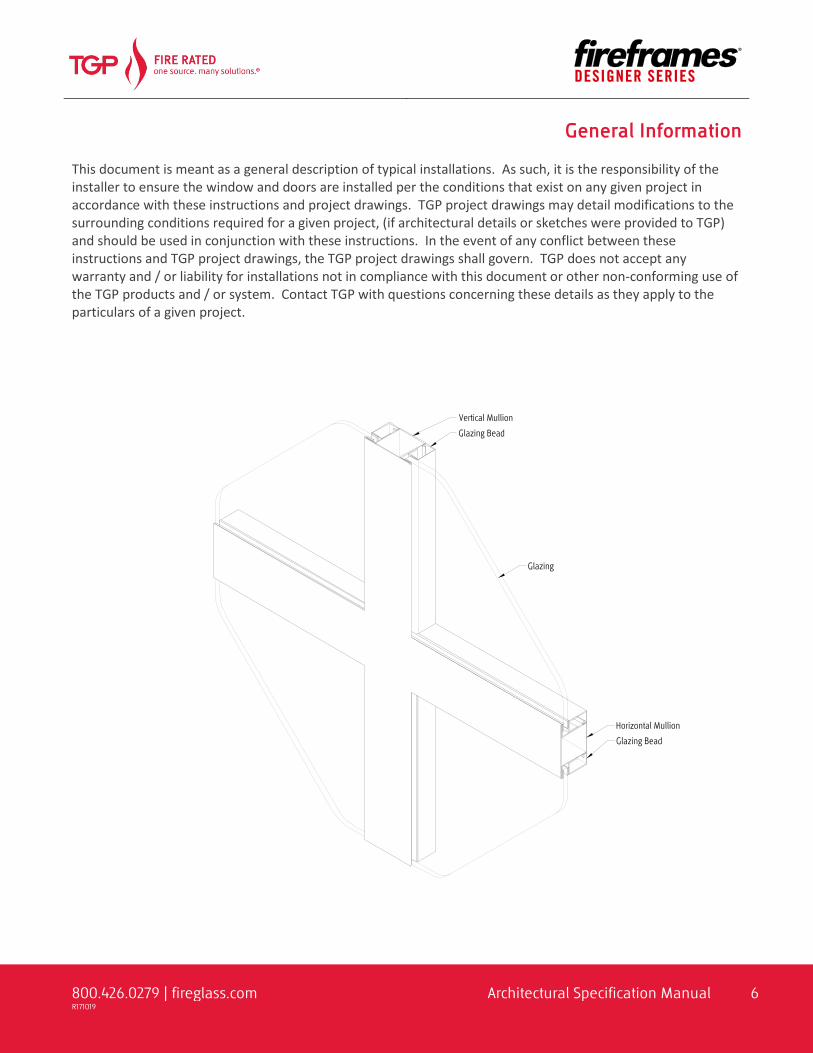
General Information This document is meant as a general description of typical installations. As such, it is the responsibility of the installer to ensure the window and doors are installed per the conditions that exist on any given project in accordance with these instructions and project drawings. TGP project drawings may detail modifications to the surrounding conditions required for a given project, (if architectural details or sketches were provided to TGP) and should be used in conjunction with these instructions. In the event of any conflict between these instructions and TGP project drawings, the TGP project drawings shall govern. TGP does not accept any warranty and / or liability for installations not in compliance with this document or other non-conforming use of the TGP products and / or system. Contact TGP with questions concerning these details as they apply to the particulars of a given project.

800.426.0279 | fireglass.com Architectural Specification Manual 7 R171019
FEATURES • Fabricated in the U.S.A. • Narrow steel profiles • Easy installation similar to typical storefront systems • Frames supplied welded or “K-D” (knock-down) ready for installation • Surface powder coated at the factory to match the desired color scheme • Stainless steel is available for 20 and 45 minute systems • Can be used with Fireglass® 20, Pilkington Pyrostop®, or FireLite® and WireLite® family of glass products • Passes positive pressure test standards UL 10C. • Variety of hardware available Note: This product is not intended for use in locations requiring a barrier to radiant heat. This product does not meet test standards ASTM E-119 or UL 263. If your jurisdiction requires “barrier to heat” framing, please contact Technical Glass Products regarding Fireframes® Heat Barrier Series. LISTINGS • Classified and labeled by Underwriters Laboratories, Inc.® (UL) and Underwriters Laboratories of Canada
(ULC). • Test report number for labeled 20/45/60/90 minute fire-rated frame assemblies is UL File No. R-19207. • Frame tested in accordance with UL 9, ASTM E283, ASTM E330, ASTM E331, AAMA 501.1, CAN4 S-106, and
NFPA 257. • Door tested in accordance with UL 10B, UL 10C, CAN 4 S-104, and NFPA 252. • Approved for use in New York City, MEA# 426-04-M. • Approved for use in Los Angeles, LARR 25798.
General Information

800.426.0279 | fireglass.com Architectural Specification Manual 8 R171019
SIZING GUIDELINES GLASS SIZES
Product Application Rating Minutes
Max. Exposed Area Max. Exposed Width Max. Exposed Height Square Inches
Square Meters Inches Millimeter Inches Millimeter
Fireglass®20 Doors (Note 2) 20 3,024 1.95 36 914 89 2,261 Doors - Dbl. Egress 20 2,034 1.31 36 914 56-1/2 1,435 FireLite® Doors 20 3,204 2.07 36 914 89 2,261 FireLite NT Doors - Dbl. Egress 20 2,034 1.31 36 914 56-1/2 1,435 FireLite Plus Transom/Sidelites 20 3,325 2.15 95 2,413 95 2,413 FireLite IGU Doors 45 3,204 2.07 36 914 89 2,261 Doors - Dbl. Egress 45 2,034 1.31 36 914 56-1/2 1,435 Transom/Sidelites/Windows 45 3,325 2.15 95 2,413 95 2,413 Doors 60 3,204 2.07 36 914 89 2,261 Doors - Dbl. Egress 60 2,034 1.31 36 914 56-1/2 1,435 Transom/Sidelites/Windows 60 3,325 2.15 95 2,413 95 2,413 Doors 90 2,034 1.31 36 914 56-1/2 1,435 Doors - Dbl. Egress - Top Lite 90 1,161 0.75 30-1/16 764 38-5/8 981
Doors - Dbl. Egress - Bottom Lite 90 1,041 0.67 30-1/16 764 34-5/8 879
Transom/Sidelites/Windows 90 2,627 1.69 56-1/2 1,435 56-1/2 1,435 WireLite® Doors 45 1,296 0.84 54 1,372 54 1,372 Doors - Dbl. Egress 45 2,034 1.31 36 914 56-1/2 1,435 Transom/Sidelites/Windows 45 1,296 0.84 54 1,372 54 1,372 (Glazed with Pemko FG3000) Transom 45 3,456 2.23 96 2,438 36 914 (Glazed with Pemko FG3000) Sidelites/Windows 45 4,608 2.97 100 2,540 100 2,540
Pilkington Pyrostop® Doors 45 3,184 2.05 35-7/8 912 88-3/4 2,254 45-200 (19 mm) Doors - Dbl. Egress 45 2,034 1.31 36 914 56-1/2 1,435 Transom/Sidelites/Windows 45 4,500 2.90 95-1/4 2,419 95-1/4 2,419 Pilkington Pyrostop® Doors 60 3,184 2.05 35-7/8 912 88-3/4 2,254 60-101 (23 mm) Doors - Dbl. Egress 60 2,034 1.31 36 914 56-1/2 1,435 Transom/Sidelites/Windows 60 5,616 3.62 96 2,438 96 2,438 Pilkington Pyrostop® Doors 60 3,184 2.05 35-7/8 912 88-3/4 2,254 60-201 (27 mm) Doors - Dbl. Egress 60 2,034 1.31 36 914 56-1/2 1,435 Transom/Sidelites/Windows 60 5,616 3.62 96 2,438 96 2,438
NOTE: 1. Individual lite sizes cannot exceed “Maximum Exposed Area” shown above.
2. The International Building Code (IBC) states that 20 minute fire-rated products that fail to pass a hose stream test may not be used outside of doors.
General Information

800.426.0279 | fireglass.com Architectural Specification Manual 9 R171019
ASSEMBLY AND DOOR SIZES
DOORS Max. Rating (Minutes)
Max. Width (Inches)
Max. Width (Millimeters)
Max. Height (Inches)
Max. Height (Millimeters)
Max. Area (Sq. Feet)
Max. Area (Sq. Meters)
Max door leaf size: 90 43 1092 95-7/8 2435 - -
Max DLO glass: 60 35-7/8 912 88-3/4 2254 3184 2.05
Max DLO glass: 90 36 914 56-1/2 1435 2034 1.31
DOUBLE EGRESS
Max door leaf size: 60 43 1092 95-7/8 2435 - --
Top glass opening 60 36 914 56-1/2 1435 2034 1.31
Bottom glass opening 60 36 914 56-1/2 1435 2034 1.31
Max door leaf size: 90 36-3/8 924 83-5/8 2124 - -
Top glass opening 90 30-1/16 764 38-5/8 981 1161 0.75
Bottom glass opening 90 30-1/16 764 34-5/8 879 1041 0.67
ASSEMBLY
Fire Windows 90 120 3048 120 3048 100 9.29 Special Purpose Fire Door And Frame Assembly 90 162 4115 162 4115 152 14.12
Special Purpose Oversized Fire Door And Frame Assembly 90
Oversized doors are not certified as to temperature transmission. Authorities Having Jurisdiction (AHJ) should be consulted as to whether the assembly is acceptable for a specific location.
* Note: Fireframes Designer Series frames with Door By Others (DBO) may be up to a maximum of 109” wide by 120” high (90 min. rating), provided the door leaf rating and size are not exceeded.
AMERICANS WITH DISABILITY ACT STANDARDS ON FIRE PROTECTION DOORS If fire doors were required to meet A.D.A. (Americans with Disability Act) Standards, many would not open or close with adequate force to prevent passage of flames and smoke. Recognizing this special fire safety need, NFPA 101 (National Fire Protection Association) allows operational features for fire doors (opening forces, closing speeds, etc.) that are different than for non-fire-rated doors. These fire “protective” steel doors carry ratings from 20-90 minutes for fire protection. Heat transfer through the door is not an issue, so they are constructed without interior insulation. CONVENTIONAL WOOD OR HOLLOW METAL DOORS IN FIREFRAMES DESIGNER SERIES FRAMES Conventional fire-rated wood or hollow metal doors can also be installed into TGP’s narrow profiled Fireframes Designer Series frame, but will require coordination with respect to preparation of door hardware. Prior to producing your shop drawings, TGP will need to evaluate relevant hardware schedule information. When ordering wood or hollow metal doors, you must supply our engineering staff with the manufacturer, model number, fabrication templates, door handing and, if required, physical samples. If TGP must prepare special fabrication drawings to accommodate your hardware needs, your project lead time may be extended.
General Information

800.426.0279 | fireglass.com Architectural Specification Manual 10 R171019
FIRE-RATED GLAZING OPTIONS Technical Glass Products provides a complete line of fire-rated glazing options to complement the Fireframes Designer Series Frame System. Alternatively, refer to your Technical Glass Products SpeciFIRE® Selection Guide, available from your sales representative or online at www.fireglass.com. Please consult your Technical Glass Products sales representative to determine the best option for your application.
Glazing Product
Available Fire Rating
(minutes) Offe
rs H
igh
Impa
ct S
afet
y
Pass
es H
ose
Stre
am T
est
Redu
ces H
eat
Tran
sfer
Com
plie
s with
En
ergy
Cod
es
Com
patib
le w
ith
TGP
Fram
ing
Prov
ides
Aco
ustic
Ba
rrie
r
Advantages / Disadvantages
Fireglass® 20 20 ●* ●
+ Moderate initial investment
- Cannot withstand thermal shock
FireLite® 20/45/60/90 ● ● + Heat resistance of
ceramic - Low impact resistance
FireLite IGU 20/45/60/90 ●* ● ● ● ●
+ Energy efficient + Acoustic Barrier + Wide choice of
appearances
FireLite NT 20/45/60/90 ●* ● ●
+ Surface applied approved fire-rated film
+ High impact resistance
FireLite Plus® 20/45/60/90 ●* ● ● + Durable laminated
construction + High impact resistance
Pilkington Pyrostop® 45/60 ●* ● ● ●** ● ● + High clarity + Larger sizes - Can be heavy
Note: * Meets CPSC 16CFR1201: Category I and II ** Complies with energy codes for doors. Consult product literature for maximum ratings in other openings.
General Information

800.426.0279 | fireglass.com Architectural Specification Manual 11 R171019
GLAZING SPECIFICATIONS Closed cell 1/2” wide single or double sided adhesive PVC glazing tape of any common brand (available from your local glazing supply house) is recommended. See “Glazing Tape” on the Material Key Chart. Refer to table below for glazing tape thickness required for specific glazing products. NOTE: Special fire-rated tape is supplied by the Fireframes manufacturer for 90 minute rated window and
door assemblies only. Glass panels exceeding 1,393 sq. inches in a 90-minute rated application must be glazed with this fire-rated glazing tape. See “Fire-Rated Glazing Tape” on the Material Key Chart.
Glazing Product Weight (Approx.) Pounds per Sq.
Ft. Glazing Thickness Glazing Tape
Thickness Used
Glazing Tape Thickness Used
(Wide Stile) Fireglass® 20 3.0 1/4” 6 mm 3/16” 5 mm 3/16” 5 mm Fireglass 20 IGU 6.5 1” 25 mm 3/16” 5 mm 3/16” 5 mm FireLite® Standard 2.4 3/16” 5 mm 3/16” 5 mm 3/16” 5 mm FireLite Premium 2.4 3/16” 5 mm 3/16” 5 mm 3/16” 5 mm FireLite IGU 5.9 1” 25 mm 1/8” 3 mm 1/8” 3 mm FireLite NT Standard 2.4 3/16” 5 mm 3/16” 5 mm 3/16” 5 mm FireLite NT Premium 2.4 3/16” 5 mm 3/16” 5 mm 3/16” 5 mm FireLite NT IGU 5.9 1” 25 mm 1/8” 3 mm 1/8” 3 mm FireLite NT Obscure 2.4 3/16” 5 mm 3/16” 5 mm 3/16” 5 mm FireLite NT Premium 2.4 3/16” 5 mm 3/16” 5 mm 3/16” 5 mm FireLite Plus® Standard 4.0 5/16” 8 mm 5/32” 4 mm 5/32” 4 mm FireLite Plus Premium 4.0 5/16” 8 mm 5/32” 4 mm 5/32” 4 mm FireLite Plus IGU Standard 7.5 1” 25 mm 3/16” 5 mm 3/16” 5 mm FireLite Plus IGU Premium 7.5 1” 25 mm 3/16” 5 mm 3/16” 5 mm FireLite Plus IGU Obscure 7.5 1” 25 mm 3/16” 5 mm 3/16” 5 mm Pilkington Pyrostop® 45-200 9.22 3/4” 19 mm 1/8” 3 mm 1/8” 3 mm Pilkington Pyrostop 60-101 10.85 7/8” 23 mm 5/32” 4 mm 5/32” 4 mm Pilkington 60-201 12.90 1-1/16” 27 mm 1/16” 2 mm 1/16” 2 mm
Figure 3 - Typical Glazing Options
General Information

800.426.0279 | fireglass.com Architectural Specification Manual 12 R171019
ARCHED TOP (RADIUS) FRAMES Fireframes Designer Series window frames can be bent to custom requirements. Refer to Figures 4 and 5 for minimum bend radius for each frame profile.
Figure 4 - Profiles
Figure 5 - Arched Top Examples
General Information

800.426.0279 | fireglass.com Architectural Specification Manual 13 R171019
HOW TO DETERMINE DOOR HANDING Doors are always viewed and identified by the secure (lockable) side of the door (except for double egress). The non-lockable side is not secured and always available for emergency egress (panic exit). NOTE: ∗ The fixed leaf in a pair can be outfitted with either a manual or automatic flushbolt. ∗∗ Active/Active pairs of doors require exit devices be installed on both leafs. ∗∗∗ Double egress pair of doors are unsecured and require exit devices be installed on both leafs.
LH Left Hand Single Door RH Right Hand Single Door
LHR Left Hand Reverse Single Door RHR Right Hand Reverse Single Door
LHA Pair Left Hand Active & Right Hand Fixed Pair of Doors ∗
RHA Pair Right Hand Active & Left Hand Fixed Pair of Doors ∗
LHRA Pair Left Hand Reverse Active & Right Hand Reverse Fixed Pair of Doors ∗
RHRA Pair Right Hand Reverse Active & Left Hand Reverse Fixed Pair of Doors ∗
LHRA/RHRA Pair (Active / Active)
Left Hand Reverse Active & Right Hand Reverse Pair of Doors ∗∗
Double Egress Dual Left Hand Reverse Pair of Doors ∗∗∗
Figure 6 - Door Handing Chart
General Information

800.426.0279 | fireglass.com Architectural Specification Manual 14 R171019
DOOR HARDWARE CONFIGURATIONS AND HARDWARE OPTIONS The Fireframes Designer Series has been developed with narrow steel profiles which exceed traditional fire-rated frame systems in aesthetics and performance. TGP offers a complete line of select hardware options which have been fit- and function-tested for use with these profiles. Not all fire-rated hardware components available are compatible with TGP’s narrow profile systems. Should you request an item of hardware not standardly supplied by TGP, please forward all relevant information (manufacturer, model number, fabrication template and if required physical sample) to TGP for evaluation by our engineering staff, to determine if it can be supplied by TGP for use. Use of non-standard hardware may incur additional cost and lead time. Compare door swing types (LH, RH, LHR, etc.) from the Door Handing Chart (Figure 6) to the chart’s types to see available hardware standards and options for each door swing combination. For detailed hardware information refer to individual cut sheets available from Technical Glass Products. Required: Required Option: Optional: Not Available: Blank
Door Swing Type LH RH LHR RHR LHRA/ RHRA (PAIR)
LHA (PAIR)
RHA (PAIR)
LHRA (PAIR)
RHRA (PAIR) Manufactuer - Notes
Door Bottom Smoke Seal Pemko – Automatically seals to floor when door is
closed. Perimeter Gaskets TGP – Double overlapping seal system provide
effective seal against weather and smoke. Weld-On Pivot TGP – Three pivots standard.
Closer
Dorma – TS9315 Surface Mounted, Pull Side standard. Dorma – TS9315GSR, with integrated coordinator.
Dorma – ITS96-1, Concealed.
LCN – 4040XP Surface Mounted, Pull Side standard. LCN – 4040XP, with Trimco 3092 coordinator.
Flushbolt Trimco – Automatic. Latches fixed door leaf. Trimco – Semi-Automatic. Latches fixed door leaf.
Exit Device and Latching
TGP – Mortise Lock and Lever Handle Trim. With panic function for emergency egress.
Dorma – Rim Exit Device. Dorma – Surface Vertical Rod. Dorma – Concealed Vertical Rod. Von Duprin – Surface Vertical Rod. Von Duprin – Concealed Vertical Rod.
Von Duprin – Rim Exit Device.
Electric Strike RCI – With mortise lock only, not for use with exit devices.
Profile Lock Cylinder TGP –Schlage C Keyway (with mortise locks only). Magnetic Shear Lock Securitron – SAM2-24 concealed mounting. Concealed Power Transfer Securitron – For use with electric options.
Power Supply Dorma or Von Duprin – Power for electric exit devices. Figure 7 - Hardware Configuration Chart
General Information

800.426.0279 | fireglass.com Architectural Specification Manual 15 R171019
Recommended Guidelines 1. REVIEW CONTRACT DOCUMENTS Review architectural drawings, specifications, and approved TGP project drawings, installation instructions, and shipping lists to become thoroughly familiar with the project. The TGP project drawings take precedence and include specific details for your installation. These installation instructions are of a general nature and cover most conditions. 2. BUILDING CODES Due to the diversity in local, state / provincial, or federal laws and the codes that govern design and application of architectural products, it is the responsibility of the individual architect / owner and installer to ensure that products selected for use on projects comply with all the applicable building codes and laws. Technical Glass Products exercises no control over the use or application of its products, glazing materials, and operating hardware and assumes no responsibility thereof. Compliance of TGP project drawings with applicable codes for a given project shall be the responsibility of the Buyer. 3. COORDINATION WITH OTHER TRADES Coordinate with the general contractor any sequence with other trades which impact installation (i.e. fire proofing, back-up walls, partitions, ceilings, mechanical ducts, converters etc.) or in which installation may impact the work of adjacent trades. 4. INSTALLATION All materials are to be installed plumb and level. 5. BENCH MARKS All work should start from bench marks and/or column lines as established by the architectural drawings and the general contractor with guaranteed accuracy. Using these datum points and lines, determine:
a. The plane of the wall in reference to offset lines provided on each floor;
b. The finish floor lines in reference to bench marks on the outer building columns; and
c. Mullion spacing from both ends of openings to prevent dimensional build-up of daylight opening.
6. SURROUNDING CONDITIONS
a. Coordination of adjacent material and construction tolerances to TGP’ s systems may be facilitated by TGP as part of preparing project drawings, and these drawings may indicate acceptable tolerances for critical dimensions. The installer should verify that surrounding construction is in accordance with the approved project drawings. Do not accept rough opening dimensions less than shown on project drawings. It is assumed that the minimal joint dimensions shown on the TGP project drawings match the field conditions. A frame may fit within a given opening but sealants may not perform as detailed if a smaller sealant joint is installed. Expansion / contraction issues may also be compromised. IF THE JOINTS ARE SMALLER THAN THAT SHOWN ON THE TGP PROJECT DRAWINGS, DO NOT PROCEED. Notify the General Contractor that the conditions are not as detailed and wait for corrective work to be completed before starting this work.

800.426.0279 | fireglass.com Architectural Specification Manual 16 R171019
b. The installer MUST notify and receive approval from TGP and the general contractor when conditions are not in accordance with approved project drawings and/or change any aspect of the structural performance of the Fireframes series before making any modifications to the TGP-furnished material or making changes which are different from those shown on the TGP project drawings. These conditions include, but are not limited to, anchor placement/location, changes in adjacent materials the anchor is being connected to or changes to dimensional relationships between framing, anchors and connection to adjacent materials.
c. TGP must review and approve any changes required prior to the subcontractor installing any “corrective” work. These reviews may incur additional charges, which must be approved by the TGP customer prior to TGP’s review.
7. FRAME CONSTRUCTION VARIES Depending on size restrictions, frames are shipped fully welded ready for installation or “K-D” (knock-down) to be assembled on site with mechanical joints. 8. FASTENING Within the body of these instructions, “fastening” means any method of securing one part to another or to adjacent materials by means other than welding, adhering or using a mechanical fastener as shown on the approved details. Only those fasteners used within the system are specified in these instructions. Due to the varying perimeter conditions and performance requirements, perimeter and anchor fasteners are not specified in these instructions and are the responsibility of the installer. 9. SEALANTS
a. Sealants must be compatible with all materials they are in contact with, including other sealant surfaces. Consult with sealant manufacturer for recommendations relative to joint size, shelf life, compatibility, cleaning/priming, tooling, adhesion, etc.
b. The chemical compatibility and/or adhesion of all glazing materials and framing sealants with each other and with like materials used in glass and frame fabrication must be established by the installer. This is required on every project.
c. If required by the project specifications, it is the responsibility of the glazing contractor to submit any documentation or samples from the sealant manufacturer indicating that glass and glazing material has been tested for chemical compatibility and / or adhesion with glazing sealants. This applies to all TGP materials in contact with any sealant. TGP will furnish samples of these materials upon request.
d. The implementation of the test results is the responsibility of the installing contractor, and includes material performance and recommendations for primers and substrate preparation required to obtain adhesion.
10. PERIMETER JOINTS Perimeter seals and/or expansion joints shown in these instructions and in the TGP project drawings are shown at nominal size. Actual dimensions may vary due to perimeter conditions and / or difference in metal temperature between the time of fabrication and the time of installation. Design and detailing have been based on a fabrication / installation temperature of 70° F (21° C). If extreme temperatures exist at time of installation, gaps between expansion members may require slight adjustment.
Recommended Guidelines

800.426.0279 | fireglass.com Architectural Specification Manual 17 R171019
Sample Elevations – Windows
Figure 8 - Window (Welded Joinery)
INTERIOR Application
Figure 9 - Window (Welded Joinery)
EXTERIOR Application
Figure 10 - Mechanical Joinery Example
INTERIOR Application
Figure 11 - Mechanical Joinery and Corner
INTERIOR Application

800.426.0279 | fireglass.com Architectural Specification Manual 18 R171019
Sample Section Details – Windows
Figure 12 - INTERIOR Application Figure 13 - EXTERIOR Application
NOTE: Install Frame Flange on the EXTERIOR of opening. Typical IGU shown.

800.426.0279 | fireglass.com Architectural Specification Manual 19 R171019
Sample Section Details – Windows
Figure 14 - INTERIOR Application
Figure 15 - EXTERIOR Application

800.426.0279 | fireglass.com Architectural Specification Manual 20 R171019
Sample Section Details – Windows
Figure 16 - INTERIOR Application - "Outside" Corner
Figure 17 - INTERIOR Application - "Inside" Corner
Figure 18 - INTERIOR Application - Mechanical Joint

800.426.0279 | fireglass.com Architectural Specification Manual 21 R171019
Sample Elevations – Single Doors
Figure 19 - Standalone Door
Figure 20 - Standalone Door By Others (DBO)
Figure 21 Single Door with Sidelite and Transom
INTERIOR - Application Shown
800.426.0279 | fireglass.com Architectural Specification Manual 22 R171019
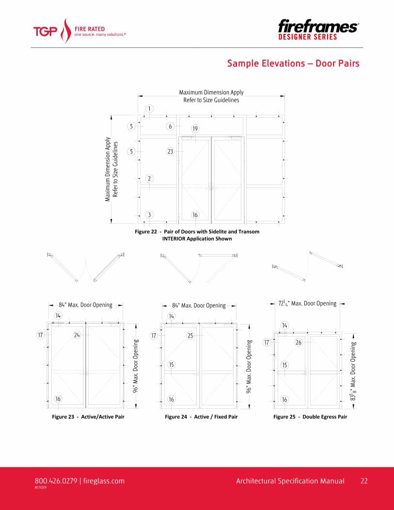
Sample Elevations – Door Pairs
Figure 22 - Pair of Doors with Sidelite and Transom
INTERIOR Application Shown
Figure 23 - Active/Active Pair
Figure 24 - Active / Fixed Pair
Figure 25 - Double Egress Pair

800.426.0279 | fireglass.com Architectural Specification Manual 23 R171019
Sample Elevations – Wide Stile Doors For Deep Backset Mortise Locks
Figure 26 - Standalone Wide Stile Door
Figure 27 - Pair of Wide Stile Doors
Active / Active
Figure 28 - Pair of Wide Style Doors
Active / Fixed

800.426.0279 | fireglass.com Architectural Specification Manual 24 R171019
Sample Section Details – Doors
Figure 29 - Standalone Door
Figure 30 Standalone Door
Jamb at Pivot Side
Figure 31 - Standalone Door
Jamb at Lever Side

800.426.0279 | fireglass.com Architectural Specification Manual 25 R171019
Sample Section Details – Doors
Figure 32 - Door with Transom
Figure 33 - Door with Extended Header

800.426.0279 | fireglass.com Architectural Specification Manual 26 R171019
Sample Section Details – Doors
Figure 34 - Fireframes Designer Series Frame with Door By Others (DBO)

800.426.0279 | fireglass.com Architectural Specification Manual 27 R171019
Sample Section Details – Doors
Figure 35 - Typical Meeting Stile Combinations

800.426.0279 | fireglass.com Architectural Specification Manual 28 R171019
Sample Section Details – Doors
Figure 36 - Wide Stile Door Details

800.426.0279 | fireglass.com Architectural Specification Manual 29 R171019
Sample Section Details – Doors
Figure 37 - Wide Stile Meeting Combinations

800.426.0279 | fireglass.com Architectural Specification Manual 30 R171019
Sample Section Details – Doors
Figure 38 - Wide Stile Jamb Combinations

800.426.0279 | fireglass.com Architectural Specification Manual 31 R171019
Sample Section Details – Doors
Figure 39 - Extra Wide Mid Rail Detail