technical information thermostatic radiator valves the
TRANSCRIPT
Technical information
Thermostatic radiator valves
Function:
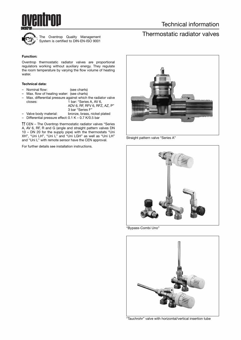
Oventrop thermostatic radiator valves are proportionalregulators working without auxiliary energy. They regulatethe room temperature by varying the flow volume of heatingwater.
Technical data:
– Nominal flow: (see charts)– Max. flow of heating water: (see charts)– Max. differential pressure against which the radiator valve
closes: 1 bar: “Series A, AV 6, ADV 6, RF, RFV 6, RFZ, AZ, P”3 bar “Series F”
– Valve body material: bronze, brass, nickel plated– Differential pressure effect: 0.1 K – 0.7 K/0.5 bar
CEN – The Oventrop thermostatic radiator valves “SeriesA, AV 6, RF, R and G (angle and straight pattern valves DN10 – DN 20 for the supply pipe) with the thermostats “UniXH”, “Uni LH”, “Uni L” and “Uni LGH” as well as “Uni LH”and "Uni L” with remote sensor have the CEN approval.
For further details see installation instructions.
Straight pattern valve “Series A”
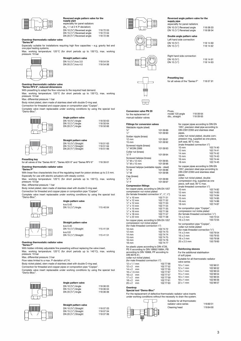
“Bypass-Combi Uno”
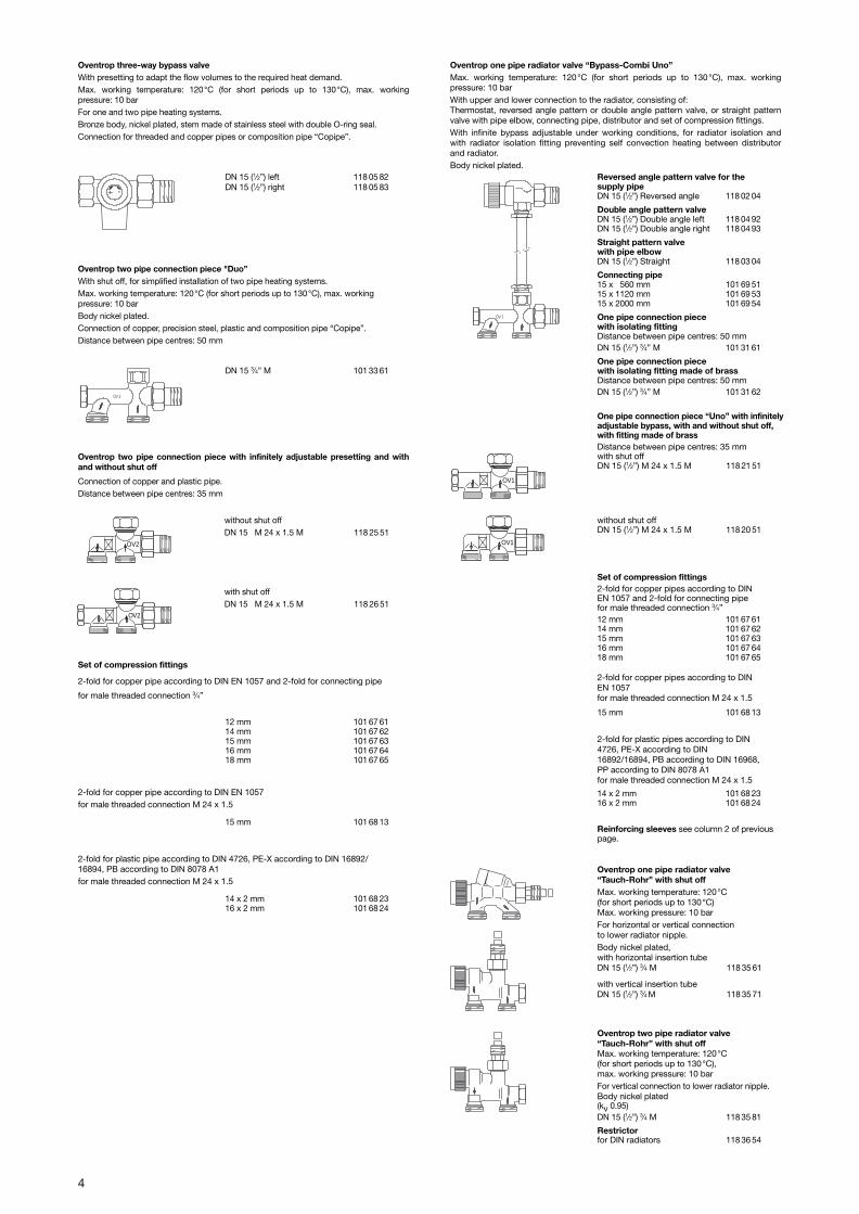
“Tauchrohr” valve with horizontal/vertical insertion tube
The Oventrop Quality ManagementSystem is certified to DIN-EN-ISO 9001

2
Tender specifications (short form)
Oventrop thermostatic radiator valve“Series A”
Max. working temperature: 120°C (for short periods up to 130°C), max working pressure:10 barLow pressure steam 0.5 bar, 110°CMax. differential pressure: 1 barBody nickel plated, stem made on stainless steel with double O-ring seal.Connection thread M 30 x 1.5Connection for threaded and copper pipes or composition pipe “Copipe”.Complete valve insert replaceable under working conditions by using the special tool”Demo-Bloc“.
Angle pattern valve
(kv 0.95 at 2 K P-deviation)
DN 10 (3⁄8”) Angle 118 00 03DN 15 (1⁄2”) Angle 118 00 04
Reversed angle pattern valve for the supply pipe
especially for panel radiators(kv 0.95 at 2 K P-deviation)
DN 10 (3⁄8”) Reversed angle 118 02 03DN 15 (1⁄2”) Reversed angle 118 02 04
Angle pattern valve
(kv 0.95 at 2 K P-deviation)
DN 10 (3⁄8”) Angle 118 45 03DN 15 (1⁄2”) Angle 118 45 04DN 20 (3⁄4”) Angle 118 45 06
Angle pattern valve
DN 10 (3⁄8”) Angle 118 37 63DN 15 (1⁄2”) Angle 118 37 64DN 20 (3⁄4”) Angle 118 37 66
Straight pattern valve
DN 10 (3⁄8”) Straight 118 38 63DN 15 (1⁄2”) Straight 118 38 64DN 20 (3⁄4”) Straight 118 38 66
Angle pattern valveDN 10 (3⁄8”) Angle 118 81 63DN 15 (1⁄2”) Angle 118 81 64DN 20 (3⁄4”) Angle 118 81 66
Presetting keyfor all valves of the “Series AV 6”, “Series ADV 6” and “Series RFV 6” 118 39 61
Reversed angle pattern valve for the supply pipeespecially for panel radiatorsDN 10 (3⁄8”) Reversed angle 118 39 63DN 15 (1⁄2”) Reversed angle 118 39 64DN 20 (3⁄4”) Reversed angle 118 39 66
Double angle pattern valve
DN 10 (3⁄8”) Double angle left 118 34 60DN 10 (3⁄8”) Double angle right 118 34 61DN 15 (1⁄2”) Double angle left 118 34 62DN 15 (1⁄2”) Double angle right 118 34 63
Reversed angle pattern valvefor the return pipe
for reversed supply and return pipe (rattling noises)
DN 10 (3⁄8”) 118 37 91DN 15 (1⁄2”) 118 37 92
Oventrop thermostatic radiator valve“Series AV 6”Limiting and presetting to adapt the flow volumes to the required heat demand withoutreplacing the valve insert.Max. working temperature: 120°C (for short periods up to 130°C), max. working pressure: 10 barMax. differential pressure: 1 barBody nickel plated, stem made of stainless steel with double O-ring seal.Connection for threaded and copper pipes or steel and composition pipe “Copipe”.Complete valve insert replaceable under working conditions by using the special tool“Demo-Bloc”.
Oventrop thermostatic radiator valve“Series ADV 6”With presetting to adapt the flow volumes to the required heat demand.Should the thermostat be removed or vandalised, the double function provokes an automatic closing of the valve to 5% of the nominal flow.Max. working temperature: 120°C (for short periods up to 130°C), max. workingpressure: 10 barMax. differential pressure: 1 barBody nickel plated, stem made of stainless steel with double O-ring seal.Connection for threaded and copper pipes or composition pipe “Copipe”.Complete valve insert replaceable under working conditions by using the special tool“Demo-Bloc”.
Reversed angle pattern valvefor the return pipe
for reversed supply and return pipe (rattling noises)
(kv 0.95 at 2 K P-deviation)
DN 10 (3⁄8”) 118 00 91DN 15 (1⁄2”) 118 00 92
Straight pattern valvefor the return pipe
(kv 0.95 at 2 K P-deviation)
DN 10 (3⁄8”) 118 01 91DN 15 (1⁄2”) 118 01 92
Oventrop thermostatic radiator valve“Series RF”, reduced dimensionsMax. working temperature: 120°C (for short periods up to 130°C), max. working pressure: 10 barLow pressure steam 0.5 bar, 110°CMax. differential pressure: 1 barBody nickel plated, stem made of stainless steel with double O-ring seal.Connection for threaded and copper pipes or composition pipe “Copipe”.Complete valve insert replaceable under working conditions by using the special tool“Demo-Bloc”.
Double angle pattern valve
(kv 0.95 at 2 K P-deviation)
DN 10 (3⁄8”) Double angle left 118 04 90DN 10 (3⁄8”) Double angle right 118 04 91DN 15 (1⁄2”) Double angle left 118 04 92DN 15 (1⁄2”) Double angle right 118 04 93
Straight pattern valveDN 10 (3⁄8”) Straight 118 82 63DN 15 (1⁄2”) Straight 118 82 64DN 20 (3⁄4”) Straight 118 82 66
Oventrop thermostatic radiator valve“Series AZ”Max. working temperature: 120°C (for short periods up to 130°C), max. working pressu-re: 10 barLow pressure steam 0.5 bar, 110°CMax. differential pressure: 1 barBody nickel plated, stem made of stainless steel with double O-ring seal.Connection for threaded and copper pipes or composition pipe “Copipe”.Complete valve insert replaceable under working conditions by using the special tool“Demo-Bloc”.
Straight pattern valve
(kv 0.95 at 2 K P-deviation)
DN 10 (3⁄8”) Straight 118 01 03DN 15 (1⁄2”) Straight 118 01 04
Straight pattern valve
(kv 0.95 at 2 K P-deviation))
DN 10 (3⁄8”) Straight 118 46 03DN 15 (1⁄2”) Straight 118 46 04DN 20 (3⁄4”) Straight 118 46 06
Straight pattern valvefor the return pipe
DN 10 (3⁄8”) 118 38 91DN 15 (1⁄2”) 118 38 92
Presetting keyfor all valves of the “Series AV 6”, “Series ADV 6” and “Series RFV 6” 118 39 61
Angle pattern valve(kv 1.1 at 2 K P-deviation)DN 10 ( 3⁄8”) Angle 118 70 03DN 15 ( 1⁄2”) Angle 118 70 04DN 20 ( 3⁄4”) Angle 118 70 06DN 25 ( 1”) Angle 118 70 08DN 32 (11⁄4”) Angle 118 70 10
Straight pattern valve(kv 1.1 at 2 K P-deviation)DN 10 ( 3⁄8”) Straight 118 71 03DN 15 ( 1⁄2”) Straight 118 71 04DN 20 ( 3⁄4”) Straight 118 71 06DN 25 ( 1”) Straight 118 71 08DN 32 (11⁄4”) Straight 118 71 10
-+
-+
3
Angle pattern valvekvs 0.45DN 15 (1⁄2”) Angle 115 40 04
Straight pattern valvekvs 0.45DN 15 (1⁄2”) Straight 115 41 04kvs 0.8DN 15 (1⁄2”) Straight 115 41 51
Oventrop thermostatic radiator valve“Series P”With linear flow characteristic line of the regulating insert for piston strokes up to 2.5 mm.Especially for use with electric actuators with steady control.Max. working temperature: 120°C (for short periods up to 130°C), max. working pressure: 10 barMax. differential pressure: 1 barBody nickel plated, stem made of stainless steel with double O-ring seal.Connection for threaded and copper pipes or composition pipe “Copipe”.Complete valve insert replaceable under working conditions by using the special tool“Demo-Bloc”.
Angle pattern valveDN 10 (3⁄8”) Angle 118 50 63DN 15 (1⁄2”) Angle 118 50 64DN 20 (3⁄4”) Angle 118 50 66
Straight pattern valveDN 10 (3⁄8”) Straight 118 51 63DN 15 (1⁄2”) Straight 118 51 64DN 20 (3⁄4”) Straight 118 51 66
Oventrop thermostatic radiator valve“Series F”With hidden infinitely adjustable fine presetting without replacing the valve insert.Max. working temperature: 120°C (for short periods up to 140°C), max. working pressure: 10 barMax. differential pressure: 3 barFlow rates limited to a max. P-deviation of 2 K. Body nickel plated, stem made of stainless steel with double O-ring seal.Connection for threaded and copper pipes or composition pipe “Copipe”.Complete valve insert replaceable under working conditions by using the special tool“Demo-Bloc”.
Oventrop thermostatic radiator valve“Series RFV 6”, reduced dimensionsWith presetting to adapt the flow volumes to the required heat demand.Max. working temperature: 120°C (for short periods up to 130°C), max. working pressure: 10 barMax. differential pressure: 1 barBody nickel plated, stem made of stainless steel with double O-ring seal.Connection for threaded and copper pipes or composition pipe “Copipe”.Complete valve insert replaceable under working conditions by using the special tool“Demo-Bloc”.
Oventrop thermostatic radiator valve“Series M”Especially suitable for installations requiring high flow capacities – e.g. gravity fed andone pipe heating systems.Max. working temperature: 120°C (for short periods up to 130°C), max. working pressure: 10 bar
Reversed angle pattern valve for the supply pipeespeciallly for panel radiators((kv 1.1 at 2 K P-deviation) DN 10 (3⁄8”) Reversed angle 118 72 03DN 15 (1⁄2”) Reversed angle 118 72 04DN 20 (3⁄4”) Reversed angle 118 72 06
Straight pattern valveDN 10 (3⁄8”) Straight 118 07 03DN 15 (1⁄2”) Straight 118 07 04DN 20 (3⁄4”) Straight 118 07 06
Reversed angle pattern valve for the supply pipeespeciallly for panel radiatorsDN 10 (3⁄8”) Reversed angle 118 08 03DN 15 (1⁄2”) Reversed angle 118 08 04
Conversion valve PN 20for the replacement ofmanual radiator valves
Pruss,model 120 angle 118 09 64dto., straight 118 09 65
Presetting keyfor all valves of the “Series F” 118 07 91
Angle pattern valveDN 10 (3⁄8”) Angle 118 06 03DN 15 (1⁄2”) Angle 118 06 04DN 20 (3⁄4”) Angle 118 06 06
Compression fittingsfor copper pipes, according to DIN EN 1057compression nut nickel plated(for female threaded connection 3⁄8”, 1⁄2”, 3⁄4”)3⁄8” x 10 mm 102 71 513⁄8” x 12 mm 102 71 521⁄2” x 12 mm 102 71 531⁄2” x 14 mm 102 71 541⁄2” x 15 mm 102 71 551⁄2” x 16 mm 102 71 563⁄4” x 18 mm 102 71 573⁄4” x 22 mm 102 71 58for copper pipes, according to DIN EN 1057compression nut nickel plated(for male threaded connection 3⁄4”)10 mm 102 74 7212 mm 102 74 7314 mm 102 74 7415 mm 102 74 7516 mm 102 74 7618 mm 102 74 77
Double angle pattern valveLeft hand side connectionDN 10 (3⁄8”) 118 14 60DN 15 (1⁄2”) 118 14 62
Right hand side connectionDN 10 (3⁄8”) 118 14 61DN 15 (1⁄2”) 118 14 63
-+
-+Straight pattern valveDN 15 (1⁄2”) kvs 3.0 118 54 04DN 20 (3⁄4”) kvs 4.0 118 54 06
Presetting keyfor all valves of the “Series AV 6”, “Series ADV 6” and “Series RFV 6” 118 39 61
Fittings for conversion valvesWeldable nipple (steel)3⁄8” 101 09 891⁄2” 101 09 90Solder nipple (brass)12 mm 101 09 9115 mm 101 09 92Screwed nipple (brass)1⁄2” M DIN 2999 101 09 93Collar nut (brass)7⁄8” F 101 09 94Screwed tailpipe (brass)7⁄8” M x 12 mm 101 09 957⁄8” M x 15 mm 101 09 96Screwed tailpipe (weldable nipple - steel)3⁄4” M 101 09 887⁄8” M 101 09 98Cap (brass)5⁄8” F 101 09 997⁄8” F 101 09 97
for copper pipes according to DIN EN1057, precision steel pipe according toDIN 2391/2393 and stainless steelpipes,collar nut nickel plated, double com-pression ring, supplied as one piece,soft seal, 95°C max. (male threaded connection 3⁄4”)10 mm 102 74 4012 mm 102 74 4114 mm 102 74 4215 mm 102 74 4316 mm 102 74 4418 mm 102 74 45
for copper pipes according to DIN EN1057, precision steel pipe according toDIN 2391/2393 and stainless steelpipes,collar nut nickel plated, double compression ring, supplied as onepiece, soft seal, 95°C max. (male threaded connection 3⁄4”)10 mm 102 74 8212 mm 102 74 8314 mm 102 74 8415 mm 102 74 8516 mm 102 74 8618 mm 102 74 87
for composition pipe “Copipe”,compression nut nickle plated (for female threaded connection 1⁄2”)14 x 2 mm 150 73 5416 x 2 mm 150 73 55
for composition pipe “Copipe”, collar nut nickle plated (for male threaded connection 3⁄4”)14 x 2 mm 150 79 5416 x 2 mm 150 79 5518 x 2 mm 150 79 5820 x 2.5 mm 150 79 60
Reinforcing sleevesFor the additional stabilisationof soft pipesSuitable for all thermostatic radiator valve series10 x 1 mm 102 96 5112 x 1 mm 102 96 5214 x 1 mm 102 96 5315 x 1 mm 102 96 5416 x 1 mm 102 96 5518 x 1 mm 102 96 5622 x 1 mm 102 96 57
Suitable for all thermostatic radiator valve series 118 80 51Cleaning head 118 84 00
OventropSpecial tool “Demo-Bloc”For the replacement of defective thermostatic radiator valve insertsunder working conditions without the necessity to drain the system.
for plastic pipes according to DIN 4726,PE-X according to DIN 16892/16894, PBaccording to DIN 16968, PP accoding toDIN 8078 A1, collar nut nickel plated, (for male threaded connection 3⁄4”)12 x 1.1 mm 102 77 6812 x 2 mm 102 77 5214 x 2 mm 102 77 5516 x 1.5 mm 102 77 6716 x 2 mm 102 77 5717 x 2 mm 102 77 5918 x 2 mm 102 77 6120 x 2 mm 102 77 63
4
Oventrop two pipe connection piece "Duo”With shut off, for simplified installation of two pipe heating systems.Max. working temperature: 120°C (for short periods up to 130°C), max. workingpressure: 10 barBody nickel plated.Connection of copper, precision steel, plastic and composition pipe “Copipe”.Distance between pipe centres: 50 mm
Oventrop two pipe connection piece with infinitely adjustable presetting and withand without shut off
Connection of copper and plastic pipe.Distance between pipe centres: 35 mm
without shut offDN 15 M 24 x 1.5 M 118 25 51
with shut offDN 15 M 24 x 1.5 M 118 26 51
Oventrop one pipe radiator valve “Bypass-Combi Uno”Max. working temperature: 120°C (for short periods up to 130°C), max. working pressure: 10 barWith upper and lower connection to the radiator, consisting of:Thermostat, reversed angle pattern or double angle pattern valve, or straight patternvalve with pipe elbow, connecting pipe, distributor and set of compression fittings.With infinite bypass adjustable under working conditions, for radiator isolation andwith radiator isolation fitting preventing self convection heating between distributorand radiator.Body nickel plated.
Reversed angle pattern valve for thesupply pipeDN 15 (1⁄2”) Reversed angle 118 02 04
Double angle pattern valveDN 15 (1⁄2”) Double angle left 118 04 92DN 15 (1⁄2”) Double angle right 118 04 93
Straight pattern valvewith pipe elbowDN 15 (1⁄2”) Straight 118 03 04
Connecting pipe15 x 560 mm 101 69 5115 x 1120 mm 101 69 5315 x 2000 mm 101 69 54
One pipe connection piecewith isolating fitting Distance between pipe centres: 50 mmDN 15 (1⁄2”) 3⁄4” M 101 31 61
One pipe connection piecewith isolating fitting made of brassDistance between pipe centres: 50 mmDN 15 (1⁄2”) 3⁄4” M 101 31 62
Set of compression fittings
2-fold for copper pipe according to DIN EN 1057 and 2-fold for connecting pipe
for male threaded connection 3⁄4”
2-fold for copper pipe according to DIN EN 1057for male threaded connection M 24 x 1.5
Oventrop one pipe radiator valve“Tauch-Rohr” with shut offMax. working temperature: 120°C(for short periods up to 130°C)Max. working pressure: 10 barFor horizontal or vertical connectionto lower radiator nipple.Body nickel plated,with horizontal insertion tubeDN 15 (1⁄2”) 3⁄4 M 118 35 61
with vertical insertion tubeDN 15 (1⁄2”) 3⁄4 M 118 35 71
Oventrop two pipe radiator valve“Tauch-Rohr” with shut offMax. working temperature: 120°C (for short periods up to 130°C), max. working pressure: 10 barFor vertical connection to lower radiator nipple.Body nickel plated(kv 0.95)DN 15 (1⁄2”) 3⁄4 M 118 35 81
Restrictorfor DIN radiators 118 36 54
OV 2
OV 1
DN 15 (1⁄2”) left 118 05 82DN 15 (1⁄2”) right 118 05 83+ -
Oventrop three-way bypass valve With presetting to adapt the flow volumes to the required heat demand.Max. working temperature: 120°C (for short periods up to 130°C), max. working pressure: 10 barFor one and two pipe heating systems.Bronze body, nickel plated, stem made of stainless steel with double O-ring seal.Connection for threaded and copper pipes or composition pipe “Copipe”.
DN 15 3⁄4” M 101 33 61
12 mm 101 67 6114 mm 101 67 6215 mm 101 67 6316 mm 101 67 6418 mm 101 67 65
15 mm 101 68 13
2-fold for plastic pipe according to DIN 4726, PE-X according to DIN 16892/16894, PB according to DIN 8078 A1for male threaded connection M 24 x 1.5
14 x 2 mm 101 68 2316 x 2 mm 101 68 24
OV2
OV2
Reinforcing sleeves see column 2 of previouspage.
2-fold for copper pipes according to DINEN 1057 for male threaded connection M 24 x 1.5
15 mm 101 68 13
2-fold for plastic pipes according to DIN4726, PE-X according to DIN16892/16894, PB according to DIN 16968,PP according to DIN 8078 A1for male threaded connection M 24 x 1.5
14 x 2 mm 101 68 2316 x 2 mm 101 68 24
Set of compression fittings2-fold for copper pipes according to DINEN 1057 and 2-fold for connecting pipefor male threaded connection 3⁄4” 12 mm 101 67 6114 mm 101 67 6215 mm 101 67 6316 mm 101 67 6418 mm 101 67 65
OV1
One pipe connection piece “Uno” with infinitelyadjustable bypass, with and without shut off,with fitting made of brassDistance between pipe centres: 35 mmwith shut offDN 15 (1⁄2”) M 24 x 1.5 M 118 21 51
without shut offDN 15 (1⁄2”) M 24 x 1.5 M 118 20 51
OV1
5
Plastic rosette coverDistance between pipe centres: 50 mmPerforation12 mm 101 66 7114 mm 101 66 7215 mm 101 667316 mm 101 66 7418 mm 101 66 75Distance between pipe centres: 35 mmPerforation 14-20 mm 101 66 84
Set of compression fittings2-fold for copper pipes according to DIN EN 1057for male threaded connection 3⁄4” 10 mm 101 68 6012 mm 101 68 6114 mm 101 68 6215 mm 101 68 6316 mm 101 68 6418 mm 101 68 65
Reinforcing sleeves see column 2 of previous page.
Oventrop one pipe radiator valvefor “TKM” systemMax. working temperature: 120°C (for shortperiods up to 130°C), max. working pressure: 10 barFor vertical connection to lower radiator nipple.Body nickel platedDN 15 (1⁄2”) 3⁄4 M 118 36 11
Oventrop two pipe radiator valvefor “TKM” systemMax. working temperature: 120°C (for shortperiods up to 130°C), max. working pressure: 10 barFor vertical connection to lower radiator nipple.Body nickel plated(kv 0.95 at 2 K P-deviation)DN 15 (1⁄2”) 3⁄4 M 118 36 61
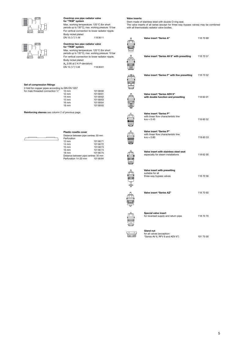
Valve inserts:Stem made of stainless steel with double O-ring seal.The valve inserts of all series (except for three-way bypass valves) may be combinedwith all thermostatic radiator valve bodies.
Valve insert “Series A” 118 70 69
Valve insert “Series AV 6” with presetting 118 70 57
Valve insert “Series F” with fine presetting 118 73 52
Valve insert “Series ADV 6”with double function and presetting 118 60 01
Valve insert “Series P”with linear flow characteristic linekvs = 0.45 118 60 52
Valve insert “Series P”with linear flow characteristic linekvs = 0.80 118 60 53
Valve insert with stainless steel seatespecially for steam installations 118 62 00
Valve insert with presettingsuitable for allthree-way bypass valves 118 70 56
Valve insert “Series AZ” 118 70 60
Special valve insertfor reversed supply and return pipe 118 70 70
Gland nutfor all valves (exception:“Series AV 6, RFV 6 and ADV 6”) 101 75 00
10 mm 101 68 6012 mm 101 68 6114 mm 101 68 6215 mm 101 68 6316 mm 101 68 6418 mm 101 68 65
6
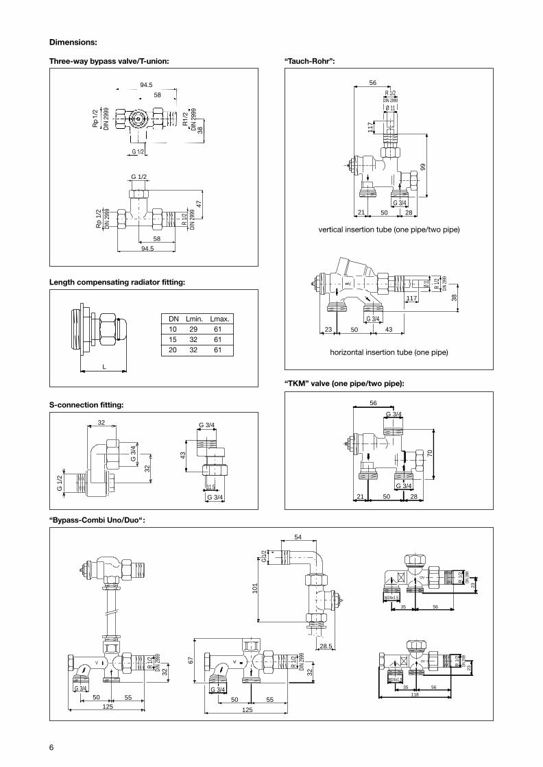
DN Lmin. Lmax.10 29 6115 32 6120 32 61
L
56
G 3/4
G 3/4
70
50 2821
R 1/
2DI
N 29
99
1255550
G 3/4
32
54
28.5
101
G 1
/2
23 50 43
117
G 3/4
Ø 11
R 1/2
DIN
2999
38
R 1/
2DI
N 29
9932
125
5550
G 3/4
67
G 3/450 2821
99
117
Ø 11
R 1/2DIN 2999
56
“Bypass-Combi Uno/Duo“:
“TKM” valve (one pipe/two pipe):
“Tauch-Rohr”:
Length compensating radiator fitting:
32
32
G 3
/4
G 1
/2
S-connection fitting:
Three-way bypass valve/T-union:
Dimensions:
94.5
58
47
G 1/2
Rp
1/2
DIN
2999
R 1/
2DI
N 29
99
G 3/4
G 3/4
11.5
43
horizontal insertion tube (one pipe)
vertical insertion tube (one pipe/two pipe)
OV
R 1
/2
23
M24x1.5
35 56
DIN
2999
118
DIN
2999
5635
M24x1.5
23
R 1
/2
OV
L
94.5
58
G 1/2
38
Rp
1/2
DIN
299
9
R1/
2D
IN 2
999
7
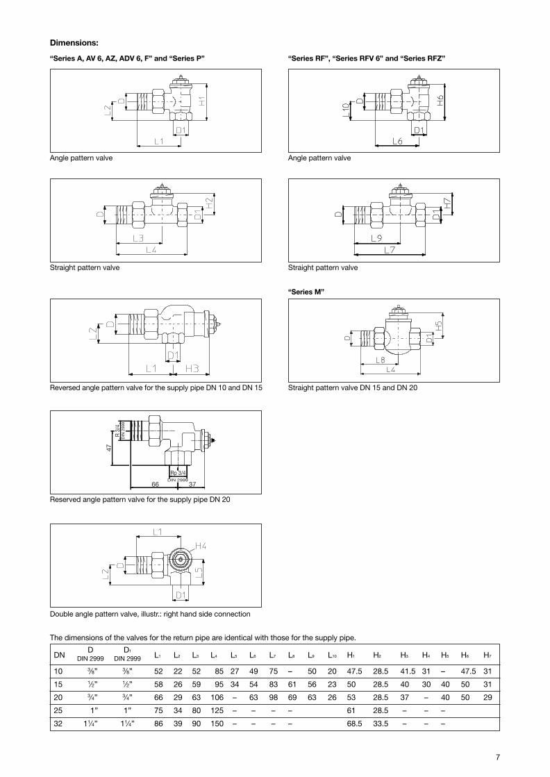
DND D1
L1 L2 L3 L4 L5 L6 L7 L8 L9 L10 H1 H2 H3 H4 H5 H6 H7DIN 2999 DIN 2999
10 3⁄8” 3⁄8” 52 22 52 85 27 49 75 – 50 20 47.5 28.5 41.5 31 – 47.5 31
15 1⁄2” 1⁄2” 58 26 59 95 34 54 83 61 56 23 50 28.5 40 30 40 50 31
20 3⁄4” 3⁄4” 66 29 63 106 – 63 98 69 63 26 53 28.5 37 – 40 50 29
25 1” 1” 75 34 80 125 – – – – 61 28.5 – – –
32 11⁄4” 11⁄4” 86 39 90 150 – – – – 68.5 33.5 – – –
The dimensions of the valves for the return pipe are identical with those for the supply pipe.
Dimensions:
“Series A, AV 6, AZ, ADV 6, F” and “Series P”
Straight pattern valve
Angle pattern valve
Reversed angle pattern valve for the supply pipe DN 10 and DN 15 Straight pattern valve DN 15 and DN 20
“Series M”
Rp 3/4DIN 2999
47
66 37
R 3
/4D
IN 2
999
Reserved angle pattern valve for the supply pipe DN 20
“Series RF”, “Series RFV 6” and “Series RFZ”
Angle pattern valve
Straight pattern valve
Double angle pattern valve, illustr.: right hand side connection

8
Series
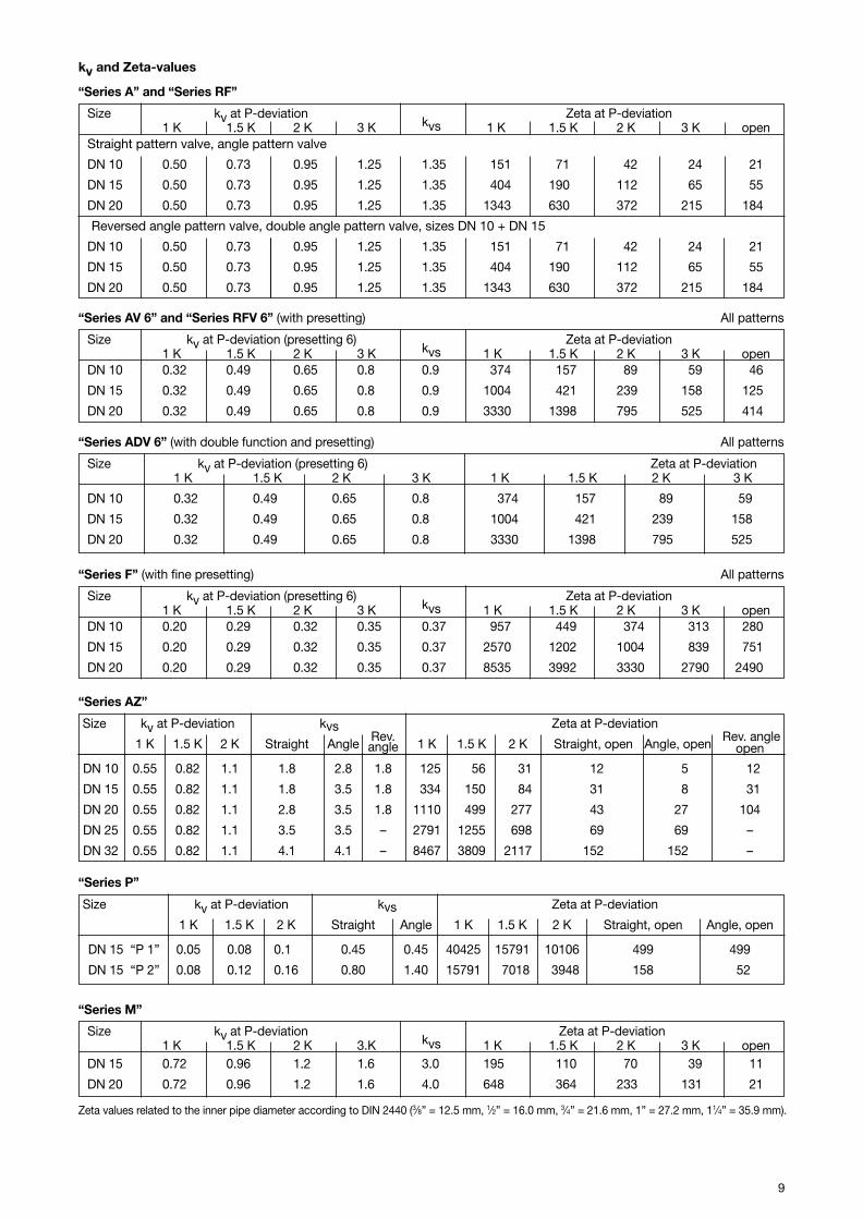
“Series A” and “Series RF”
“Series AV 6“ and “Series RFV 6”
“Series ADV 6”
“Series F”
Model with infinitely adjustable fine presetting: for twopipe heating systems with high temperature differenceand low flow rates.
Standard model for all one and two pipe heating systems.
The valves of the “Series A” and “Series RF” have a kvvalue of 0.95 at 2 K P-deviation.
Model with presetting: for two pipe heating systems withnormal temperature difference.
The valves of the “Series AV 6” and “Series RFV 6” are fitted with a presettable valve insert and therefore allow aproblem-free adaptation of the flow rates.
Model with presetting and double function.
Should the thermostat be removed or vandalised, thedouble function provokes and automatic closing of thevalve to 5% of the nominal flow.
“Bypass-Combi”
One pipe radiator valve “Bypass-Combi Uno”
Installation set for a problem-free installation of one pipeheating systems.
“Tauch-Rohr”
“Tauch-Rohr” valves for one pipe heating systems
Three-way bypass valveIllustr. Left hand side connection
For one and two pipe heating systems. The valves areadjusted to a 40% radiator flow share at 2 K P-deviation.
9
Size kv at P-deviation Zeta at P-deviation1 K 1.5 K 2 K 3 K kvs 1 K 1.5 K 2 K 3 K open
Straight pattern valve, angle pattern valve
DN 10 0.50 0.73 0.95 1.25 1.35 151 71 42 24 211
DN 15 0.50 0.73 0.95 1.25 1.35 404 190 112 65 551
DN 20 0.50 0.73 0.95 1.25 1.35 1343 630 372 215 1841
Reversed angle pattern valve, double angle pattern valve, sizes DN 10 + DN 15
DN 10 0.50 0.73 0.95 1.25 1.35 151 71 42 24 211
DN 15 0.50 0.73 0.95 1.25 1.35 404 190 112 65 551
DN 20 0.50 0.73 0.95 1.25 1.35 1343 630 372 215 1841
kv and Zeta-values
Size kv at P-deviation (presetting 6) Zeta at P-deviation1 K 1.5 K 2 K 3 K kvs 1 K 1.5 K 2 K 3 K open
DN 10 0.32 0.49 0.65 0.8 0.9 1374 1157 189 159 461
DN 15 0.32 0.49 0.65 0.8 0.9 1004 1421 239 158 1251
DN 20 0.32 0.49 0.65 0.8 0.9 3330 1398 795 525 4141
Size kv at P-deviation (presetting 6) Zeta at P-deviation1 K 1.5 K 2 K 3 K 1 K 1.5 K 2 K 3 K
DN 10 0.32 0.49 0.65 0.8 1374 1157 189 59
DN 15 0.32 0.49 0.65 0.8 1004 1421 239 158
DN 20 0.32 0.49 0.65 0.8 3330 1398 795 525
Zeta values related to the inner pipe diameter according to DIN 2440 (3⁄8” = 12.5 mm, 1⁄2” = 16.0 mm, 3⁄4” = 21.6 mm, 1” = 27.2 mm, 11⁄4” = 35.9 mm).
“Series ADV 6” (with double function and presetting) All patterns
“Series AV 6” and “Series RFV 6” (with presetting) All patterns
“Series F” (with fine presetting) All patterns
“Series M”
“Series P”
Size kv at P-deviation kvsRev.
Zeta at P-deviationRev. angle1 K 1.5 K 2 K Straight Angle angle 1 K 1.5 K 2 K Straight, open Angle, open open
DN 10 0.55 0.82 1.1 1.8 2.8 1.8 1125 1156 1131 112 115 112
DN 15 0.55 0.82 1.1 1.8 3.5 1.8 1334 1150 1184 131 118 131
DN 20 0.55 0.82 1.1 2.8 3.5 1.8 1110 1499 1277 143 127 104
DN 25 0.55 0.82 1.1 3.5 3.5 – 2791 1255 1698 169 169 –
DN 32 0.55 0.82 1.1 4.1 4.1 – 8467 3809 2117 152 152 –
“Series AZ”
“Series A” and “Series RF”
Size kv at P-deviation kvs Zeta at P-deviation
1 K 1.5 K 2 K Straight Angle 1 K 1.5 K 2 K Straight, open Angle, open
DN 15 “P 1” 0.05 0.08 0.16 0.45 0.45 40425 15791 10106 499 499
DN 15 “P 2” 0.08 0.12 0.16 0.80 1.40 15791 17018 13948 158 152
Size kv at P-deviation (presetting 6) Zeta at P-deviation1 K 1.5 K 2 K 3 K kvs 1 K 1.5 K 2 K 3 K open
DN 10 0.20 0.29 0.32 0.35 0.37 1957 1449 1374 1313 2801
DN 15 0.20 0.29 0.32 0.35 0.37 2570 1202 1004 1839 7511
DN 20 0.20 0.29 0.32 0.35 0.37 8535 3992 3330 2790 24901
Size kv at P-deviation Zeta at P-deviation1 K 1.5 K 2 K 3.K kvs 1 K 1.5 K 2 K 3 K open
DN 15 0.72 0.96 1.2 1.6 3.0 195 1110 170 139 111
DN 20 0.72 0.96 1.2 1.6 4.0 648 1364 233 131 211

10
Charts
Chart 1
Oventrop thermostatic radiator valves “Series A” and “Series RF”All patterns and sizes at 1 to 3 K P-deviation
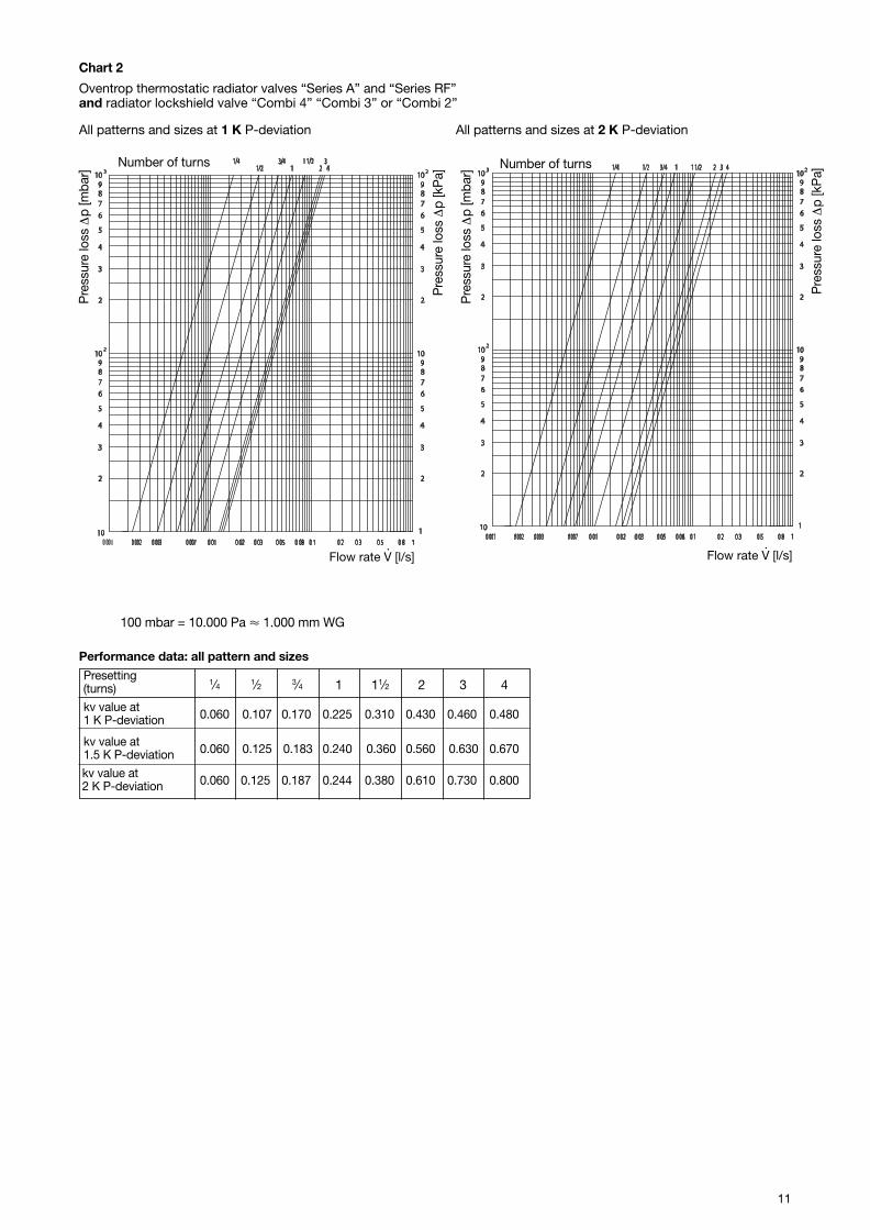
100 mbar = 10.000 Pa � 1.000 mm WG
Flow rate V [l/s]
Pre
ssur
e lo
ss ∆
p [m
bar]
Pre
ssur
e lo
ss∆
p [k
Pa]
P-deviation
P-deviation 1 K 1.5 K 2 K 3 K max.
kv 0.50 0.73 0.95 1.25 1.35
.
11
Chart 2
Oventrop thermostatic radiator valves “Series A” and “Series RF”and radiator lockshield valve “Combi 4” “Combi 3” or “Combi 2”
Presetting(turns)
kv value at0.060 0.107 0.170 0.225 0.310 0.430 0.460 0.4801 K P-deviation
kv value at0.060 0.125 0.183 0.240 0.360 0.560 0.630 0.6701.5 K P-deviation
kv value at0.060 0.125 0.187 0.244 0.380 0.610 0.730 0.8002 K P-deviation
1⁄4 1⁄2 3⁄4 1 11⁄2 2 3 4
100 mbar = 10.000 Pa � 1.000 mm WG
Number of turns
Flow rate V [l/s]·
Pre
ssur
e lo
ss ∆
p [m
bar]
Pre
ssur
e lo
ss ∆
p [k
Pa]
Number of turns
Pre
ssur
e lo
ss ∆
p [m
bar]
Pre
ssur
e lo
ss ∆
p [k
Pa]
Flow rate V [l/s]·
All patterns and sizes at 1 K P-deviation All patterns and sizes at 2 K P-deviation
Performance data: all pattern and sizes

12
Chart 3
Oventrop thermostatic radiator valves “Series AV 6”, “Series RFV 6” and “Series ADV 6” with presettingD
evia
tion
[%]
Presetting values
Flow tolerances depending on the presetting:According to DIN EN 215 at 2 K P-deviation
Performance data: all patterns and sizes
Presetting 1 2 3 4 5 6
kv value at0.055 0.141 0.221 0.247 0.28 0.32
1K P-deviation
kv value at0.055 0.170 0.296 0.370 0.42 0.49
1.5K P-deviation
kv value at0.055 0.170 0.313 0.446 0.56 0.65
2K P-deviation
Presetting
Flow rate V [l/s]·
30 dB[A]30 dB[A]
2 6543
1010
2
3
4
5
6
789
1010
2
3
4
5
6
789
1010
1
2
3
4
5
6
789
1010
2
3
4
5
6
789
10103 2
0.02 0.20.03 0.30.050.05 0.50.080.08 0.80.1 1
2
0.0020.002 0.0030.003 0.0070.007 0.010.010.0010.001
1
Pre
ssur
e lo
ss ∆
p [m
bar]
Pre
ssur
e lo
ss ∆
p [k
Pa]
Presetting
Pre
ssur
e lo
ss ∆
p [m
bar]
Pre
ssur
e lo
ss ∆
p [k
Pa]
Flow rate V [l/s]·
All patterns and sizes at 1 K P-deviation All patterns and sizes at 2 K P-deviation
13
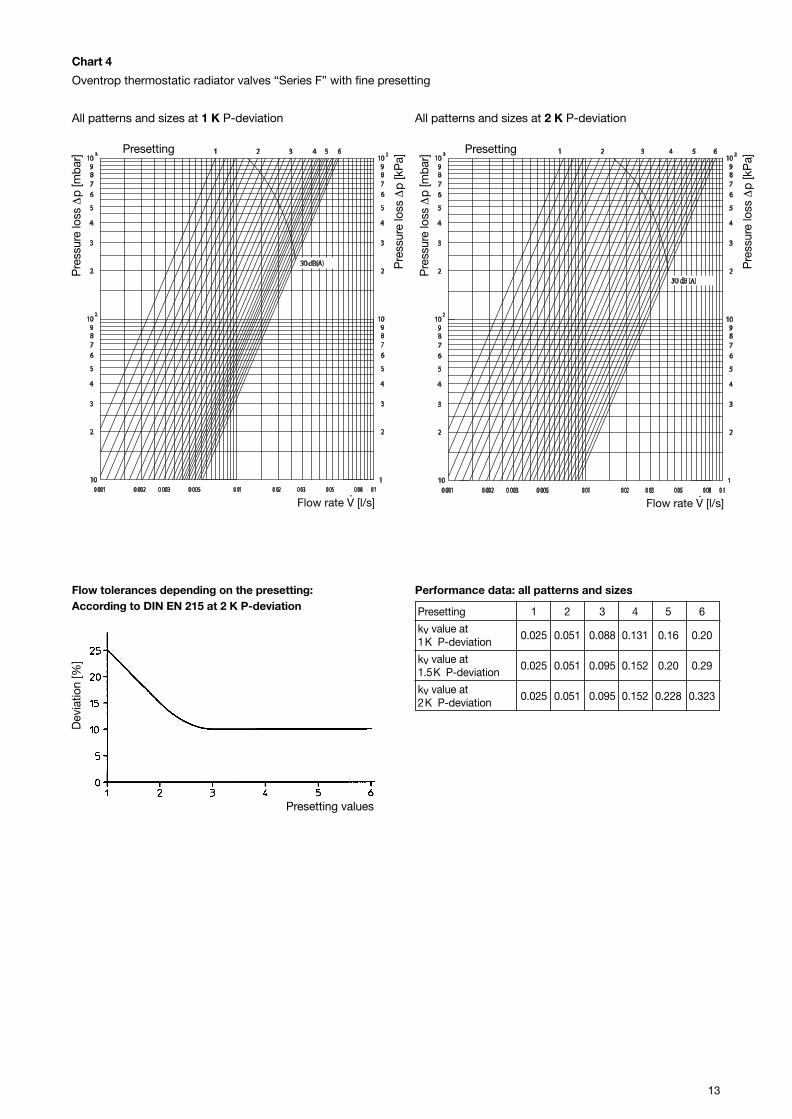
Chart 4
Oventrop thermostatic radiator valves “Series F” with fine presetting D
evia
tion
[%]
Presetting values
Flow tolerances depending on the presetting:According to DIN EN 215 at 2 K P-deviation
Performance data: all patterns and sizes
Presetting 1 2 3 4 5 6
kv value at0.025 0.051 0.088 0.131 0.16 0.20
1K P-deviation
kv value at0.025 0.051 0.095 0.152 0.20 0.29
1.5K P-deviation
kv value at0.025 0.051 0.095 0.152 0.228 0.323
2K P-deviation
Presetting
Flow rate V [l/s]·
Pre
ssur
e lo
ss ∆
p [m
bar]
Pre
ssur
e lo
ss ∆
p [k
Pa]
Presetting
Pre
ssur
e lo
ss ∆
p [m
bar]
Pre
ssur
e lo
ss ∆
p [k
Pa]
Flow rate V [l/s]·
All patterns and sizes at 1 K P-deviation All patterns and sizes at 2 K P-deviation
14
0.010.01 0.020.02 0.030.03
2K2K1.5K
1.5K
P-de
viatio
n 1K
P-de
viatio
n 1K
10
2
3
4
5
6
789
10
2
3
4
5
6
789
10
1
2
3
4
5
6
789
110
2
3
4
5
6
789
110
0.050.05 0.60.6 0.80.8 10.10.1 0.20.2 0.30.3 0.40.4
2
23
0.070.07
3/8"
, 1/2
" St
raig
ht a
nd R
ever
sed
angl
e ; 3
/4" R
ever
sed
angl
e
3/8"
, 1/2
" St
raig
ht a
nd R
ever
sed
angl
e ; 3
/4" R
ever
sed
angl
e3/
8" A
ngle
and
3/4
" Str
aigh
t
3/8"
Ang
le a
nd 3
/4" S
trai
ght
1/2"
Ang
le, 3
/4" A
ngle
, 1" A
ngle
and
Str
aigh
t
1/2"
Ang
le, 3
/4" A
ngle
, 1" A
ngle
and
Str
aigh
t1
1/4"
Ang
le a
nd S
trai
ght
1 1/
4" A
ngle
and
Str
aigh
t
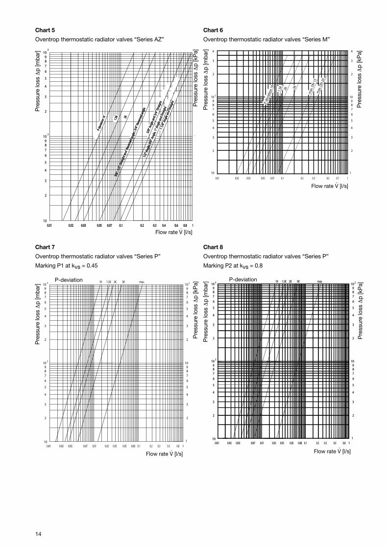
Chart 5
Oventrop thermostatic radiator valves “Series AZ”P
ress
ure
loss
∆p
[mba
r]
Pre
ssur
e lo
ss ∆
p [k
Pa]
1K
0.001 0.010.0070.0030.002
2
10.1 0.80.08 0.50.05 0.30.03 0.20.02
23 10987
6
5
4
3
2
10987
6
5
4
3
2
1
10987
6
5
4
3
2
10987
6
5
4
3
2
10
2K 3K max.1.5K
Chart 7
Oventrop thermostatic radiator valves “Series P”
Marking P1 at kvs = 0.45
Chart 8
Oventrop thermostatic radiator valves “Series P”
Marking P2 at kvs = 0.8
Pre
ssur
e lo
ss ∆
p [m
bar]
Pre
ssur
e lo
ss ∆
p [k
Pa]
max
. DN
20
P-de
viat
ion
1K
max
. DN
15
2K 3K
1.5K
0.01 0.05 0.07 0.10.02 0.03 0.2 0.3
2
10
2
3
4
5
6
789
10
2
3
4
1
2
3
4
5
6
789
10
2
3
4
0.5 0.7 1
Chart 6
Oventrop thermostatic radiator valves “Series M”
Pre
ssur
e lo
ss ∆
p [m
bar]
Pre
ssur
e lo
ss ∆
p [k
Pa]
1K1K
0.0010.001 0.010.010.0070.0070.0030.0030.0020.002
2
10.10.1 0.80.80.080.08 0.50.50.050.05 0.30.30.030.03 0.20.20.020.02
23 1010987
6
5
4
3
2
1010987
6
5
4
3
2
1
1010987
6
5
4
3
2
1010987
6
5
4
3
2
1010
2K2K 3K3K max.max.1.5K1.5K
Pre
ssur
e lo
ss ∆
p [m
bar]
Pre
ssur
e lo
ss ∆
p [k
Pa]
P-deviation P-deviation
· Flow rate V [l/s]
· Flow rate V [l/s]
· Flow rate V [l/s]
· Flow rate V [l/s]

15
Chart 8
Oventrop thermostatic radiator valves “Series A”, “Series RF”, “Series AV 6”, “Series ADV 6”, “Series RFV” and “Series F”: design ranges
Example: V = 0.033 l/s ∆p = 3 kPa kv = 0,7 (read off flow chart)
Valves of the “Series A” and “Series RF” can be used. Choice of valves see flow charts 1-4
Radiator valve design:
Oventrop thermostatic radiator valves permit a “room-by-room” adaptation of the heat output by using:
– thermostatic radiator valves with presetting (“Series AV 6”,“Series RFV 6”, "Series ADV 6” with presetting and“Series F” with fine presetting)
– thermostatic radiator valves “Series A” and “Series RF”combined with presettable radiator lockshield valves“Combi 4”, “Combi 3” and “Combi 2”
Official approvals:
Oventrop thermostatic radiator valves correspond to:
– the EN 215 standard (Reg.-No. 6T0002)
– the DIN 3841 standard, part 1
the requirements of the US-Army, Germany (approvedaccording to decree EUDED-TEM dated 04.01.1984)
– BS 7556 standard
In addition, the thermostatic radiator valves of the “Series F”correspond to:
– the directions of the Association for District Heating(AGFW)
– the conditions of the company Esso (TA list)
.Pressure loss ∆p [mbar]
”Ser
ies
F“
”Ser
ies
AV 6
“, ”
RFV
6“,
”an
d ”A
DV
6“(in
finite
ly a
djus
tabl
e pr
eset
ting)
”Ser
ies
A“
and
”RF“
Pressure loss ∆p [kPa]
(infin
itely
adj
usta
ble
fine
pres
ettin
g)
P-deviation
16
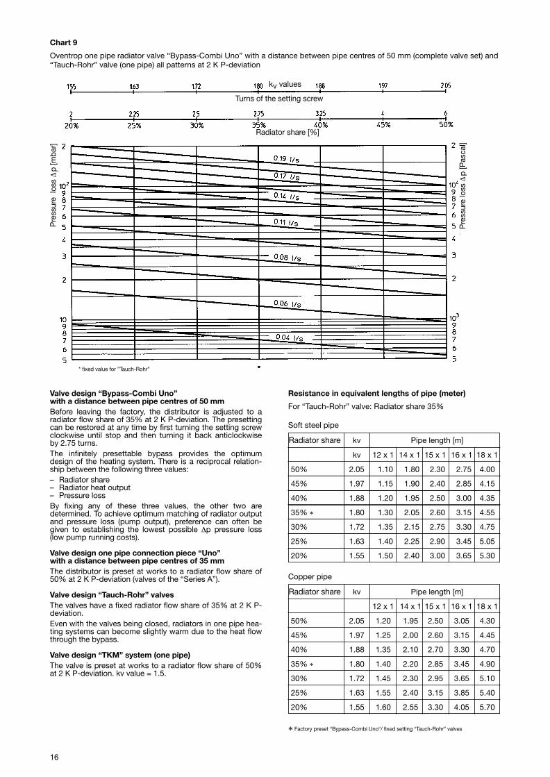
Valve design “Bypass-Combi Uno”with a distance between pipe centres of 50 mmBefore leaving the factory, the distributor is adjusted to aradiator flow share of 35% at 2 K P-deviation. The presettingcan be restored at any time by first turning the setting screwclockwise until stop and then turning it back anticlockwiseby 2.75 turns.The infinitely presettable bypass provides the optimumdesign of the heating system. There is a reciprocal relation-ship between the following three values:– Radiator share– Radiator heat output– Pressure lossBy fixing any of these three values, the other two are determined. To achieve optimum matching of radiator outputand pressure loss (pump output), preference can often begiven to establishing the lowest possible ∆p pressure loss(low pump running costs).
Valve design one pipe connection piece “Uno”with a distance between pipe centres of 35 mmThe distributor is preset at works to a radiator flow share of50% at 2 K P-deviation (valves of the “Series A”).
Valve design “Tauch-Rohr” valvesThe valves have a fixed radiator flow share of 35% at 2 K P-deviation. Even with the valves being closed, radiators in one pipe hea-ting systems can become slightly warm due to the heat flowthrough the bypass.
Valve design “TKM” system (one pipe)The valve is preset at works to a radiator flow share of 50%at 2 K P-deviation. kv value = 1.5.
Resistance in equivalent lengths of pipe (meter)
For “Tauch-Rohr” valve: Radiator share 35%
* Factory preset “Bypass-Combi Uno“/ fixed setting “Tauch-Rohr” valves
Chart 9
Oventrop one pipe radiator valve “Bypass-Combi Uno” with a distance between pipe centres of 50 mm (complete valve set) and“Tauch-Rohr” valve (one pipe) all patterns at 2 K P-deviation
* fixed value for ”Tauch-Rohr”
Pre
ssur
e lo
ss ∆
p [m
bar]
Turns of the setting screw
Radiator share [%]
kv values
Pre
ssur
e lo
ss ∆
p [P
asca
l]
Radiator share kv Pipe length [m]
kv 12 x 1 14 x 1 15 x 1 16 x 1 18 x 1
50% 2.05 1.10 1.80 2.30 2.75 4.00
45% 1.97 1.15 1.90 2.40 2.85 4.15
40% 1.88 1.20 1.95 2.50 3.00 4.35
35% * 1.80 1.30 2.05 2.60 3.15 4.55
30% 1.72 1.35 2.15 2.75 3.30 4.75
25% 1.63 1.40 2.25 2.90 3.45 5.05
20% 1.55 1.50 2.40 3.00 3.65 5.30
Soft steel pipe
Radiator share kv Pipe length [m]
12 x 1 14 x 1 15 x 1 16 x 1 18 x 1
50% 2.05 1.20 1.95 2.50 3.05 4.30
45% 1.97 1.25 2.00 2.60 3.15 4.45
40% 1.88 1.35 2.10 2.70 3.30 4.70
35% * 1.80 1.40 2.20 2.85 3.45 4.90
30% 1.72 1.45 2.30 2.95 3.65 5.10
25% 1.63 1.55 2.40 3.15 3.85 5.40
20% 1.55 1.60 2.55 3.30 4.05 5.70
Copper pipe
17
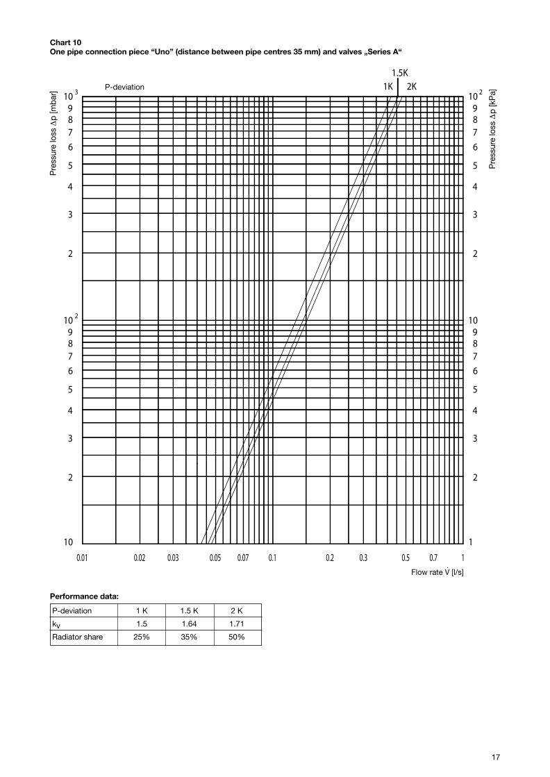
Chart 10One pipe connection piece “Uno” (distance between pipe centres 35 mm) and valves „Series A“
Pre
ssur
e lo
ss ∆
p [m
bar]
Pre
ssur
e lo
ss ∆
p [k
Pa]
10.70.5
23 10987
6
5
4
3
2
10987
6
5
4
3
2
1
10987
6
5
4
3
2
10987
6
5
4
3
2
10
2
0.30.20.030.02 0.10.070.050.01
1K 2K1.5K
P-deviation
Performance data:
P-deviation 1 K 1.5 K 2 K
kv 1.5 1.64 1.71
Radiator share 25% 35% 50%
· Flow rate V [l/s]
18
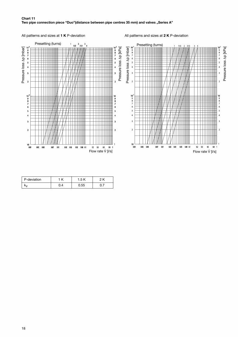
Chart 11Two pipe connection piece “Duo”(distance between pipe centres 35 mm) and valves „Series A”
P-deviation 1 K 1.5 K 2 K
kv 0.4 0.55 0.7
Presetting (turns)
Flow rate V [l/s]·
21/211/2 432
1010
2
3
4
5
6
789
1010
2
3
4
5
6
789
1010
1
2
3
4
5
6
789
1010
2
3
4
5
6
789
10103 2
0.020.02 0.20.20.030.03 0.30.30.050.05 0.50.50.080.08 0.80.80.10.1 1
2
0.0020.002 0.0030.003 0.0070.007 0.010.010.0010.001
1
Pre
ssur
e lo
ss ∆
p [m
bar]
Pre
ssur
e lo
ss ∆
p [k
Pa]
Presetting (turns)
Pre
ssur
e lo
ss ∆
p [m
bar]
Pre
ssur
e lo
ss ∆
p [k
Pa]
Flow rate V [l/s]·
All patterns and sizes at 1 K P-deviation All patterns and sizes at 2 K P-deviation
19
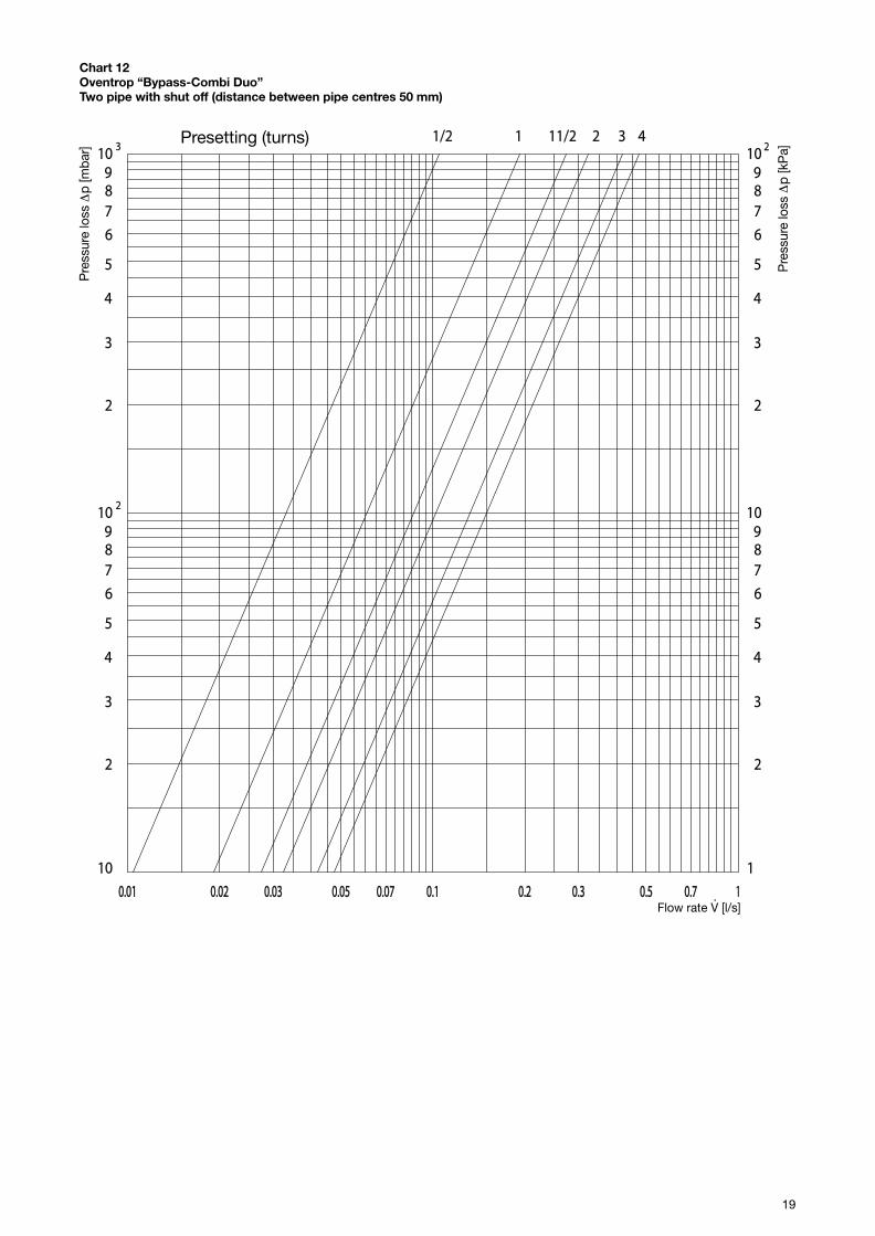
Chart 12Oventrop “Bypass-Combi Duo”Two pipe with shut off (distance between pipe centres 50 mm)
Pre
ssur
e lo
ss ∆
p [m
bar]
Pre
ssur
e lo
ss ∆
p [k
Pa]
211/211/2
10.70.70.50.5
23 10987
6
5
4
3
2
10987
6
5
4
3
2
1
10987
6
5
4
3
2
10987
6
5
4
3
2
10
2
0.30.30.20.20.030.030.020.02 0.10.10.070.070.050.050.010.01
3 4Presetting (turns)
· Flow rate V [l/s]
Subject to technical modification without notice.
Product range 1 Printed on paper free fromti 5-1/10/2004/MW chlorine bleaching.
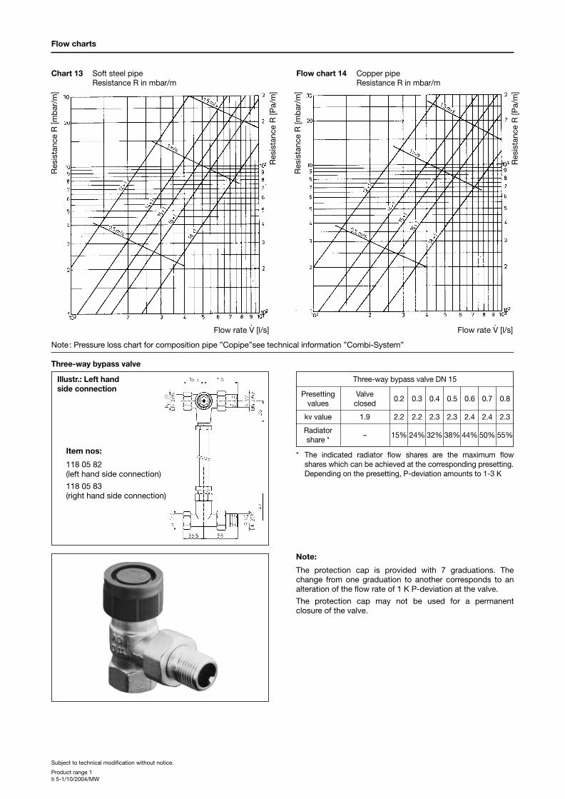
Illustr.: Left handside connection
Flow charts
Chart 13 Soft steel pipeResistance R in mbar/m
Item nos:
118 05 82(left hand side connection)
118 05 83(right hand side connection)
Note:
The protection cap is provided with 7 graduations. Thechange from one graduation to another corresponds to analteration of the flow rate of 1 K P-deviation at the valve.
The protection cap may not be used for a permanentclosure of the valve.
Flow chart 14 Copper pipeResistance R in mbar/m
Res
ista
nce
R [m
bar
/m]
Res
ista
nce
R [P
a/m
]
Res
ista
nce
R [m
bar
/m]
Res
ista
nce
R [P
a/m
]
·Flow rate V [l/s]
·Flow rate V [l/s]
Three-way bypass valve
Note: Pressure loss chart for composition pipe ”Copipe”see technical information ”Combi-System”
Three-way bypass valve DN 15
Presetting Valve0.2 0.3 0.4 0.5 0.6 0.7 0.8
values closed
kv value 1.9 2.2 2.2 2.3 2.3 2.4 2.4 2.3
Radiator– 15% 24% 32% 38% 44% 50% 55%
share *
* The indicated radiator flow shares are the maximum flowshares which can be achieved at the corresponding presetting.Depending on the presetting, P-deviation amounts to 1-3 K