technical leaflet gtu c 220 - de dietrich 2 presentation models available gtu c 220 boilers are...
TRANSCRIPT
F U E L O I L C O N D E N S I N G B O I L E R S
Heating only (DHW production by independent tank)
Condensing boiler
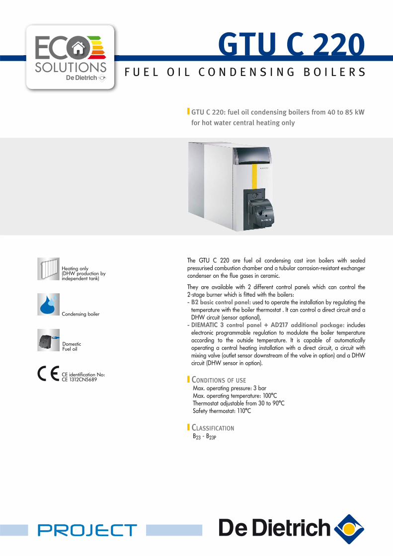
The GTU C 220 are fuel oil condensing cast iron boilers with sealed pressurised combustion chamber and a tubular corrosion-resistant exchanger condenser on the flue gases in ceramic.
They are available with 2 different control panels which can control the 2-stage burner which is fitted with the boilers:- B2 basic control panel: used to operate the installation by regulating the
temperature with the boiler thermostat . It can control a direct circuit and a DHW circuit (sensor optional),
- DIEMATIC 3 control panel + AD217 additional package: includes electronic programmable regulation to modulate the boiler temperature according to the outside temperature. It is capable of automatically operating a central heating installation with a direct circuit, a circuit with mixing valve (outlet sensor downstream of the valve in option) and a DHW circuit (DHW sensor in option).
CONDITIONS OF USEMax. operating pressure: 3 barMax. operating temperature: 100°CThermostat adjustable from 30 to 90°CSafety thermostat: 110°C
CLASSIFICATIONB23 - B23P
DomesticFuel oil
CE identification No: CE 1312CN5689
GTU C 220: fuel oil condensing boilers from 40 to 85 kW
for hot water central heating only
GTU C 220
PROJECT
2
PRESENTATION
MODELS AVAILABLE
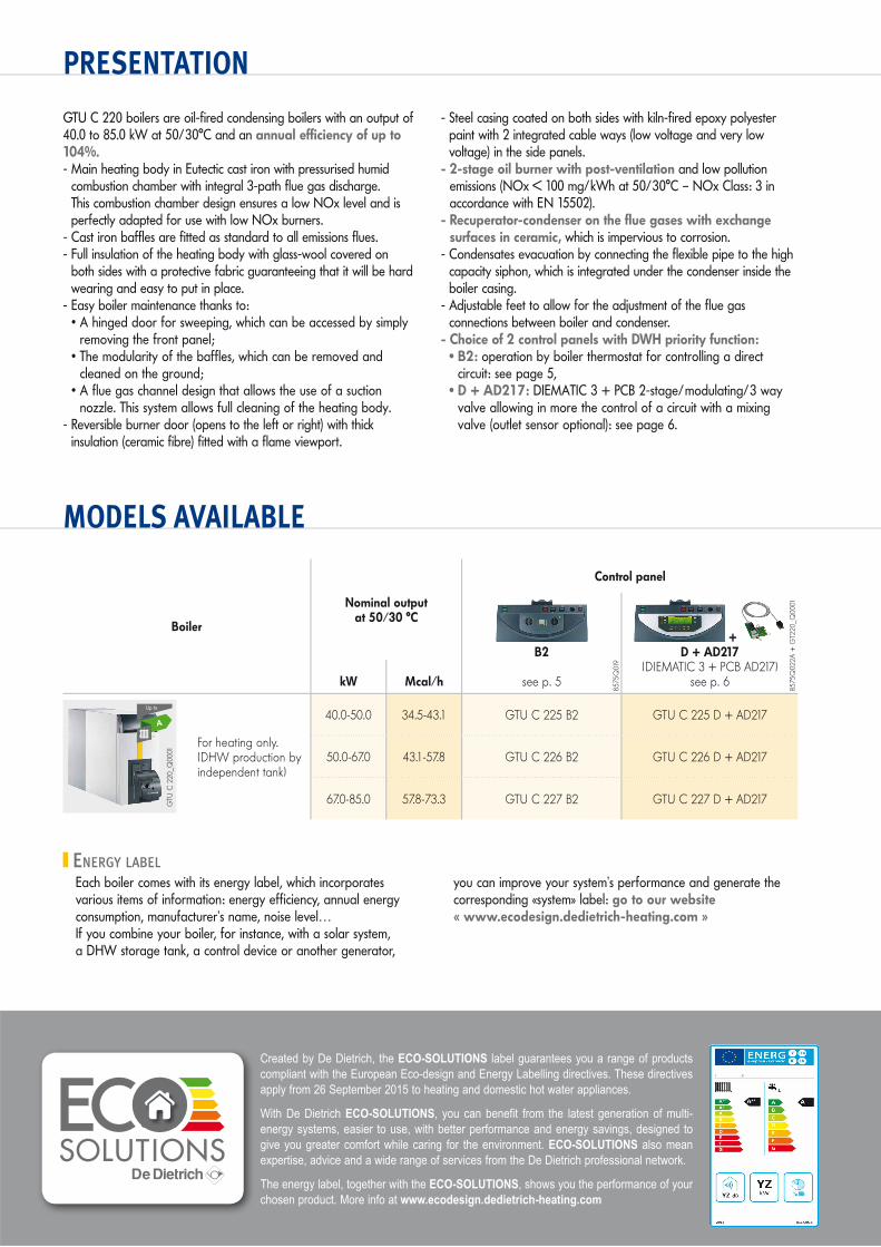
GTU C 220 boilers are oil-fired condensing boilers with an output of 40.0 to 85.0 kW at 50/30°C and an annual efficiency of up to 104%.- Main heating body in Eutectic cast iron with pressurised humid
combustion chamber with integral 3-path flue gas discharge. This combustion chamber design ensures a low NOx level and is perfectly adapted for use with low NOx burners.
- Cast iron baffles are fitted as standard to all emissions flues.- Full insulation of the heating body with glass-wool covered on
both sides with a protective fabric guaranteeing that it will be hard wearing and easy to put in place.
- Easy boiler maintenance thanks to:• A hinged door for sweeping, which can be accessed by simply
removing the front panel;• The modularity of the baffles, which can be removed and
cleaned on the ground;• A flue gas channel design that allows the use of a suction
nozzle. This system allows full cleaning of the heating body.- Reversible burner door (opens to the left or right) with thick
insulation (ceramic fibre) fitted with a flame viewport.
- Steel casing coated on both sides with kiln-fired epoxy polyester paint with 2 integrated cable ways (low voltage and very low voltage) in the side panels.
- 2-stage oil burner with post-ventilation and low pollution emissions (NOx < 100 mg/kWh at 50/30°C – NOx Class: 3 in accordance with EN 15502).
- Recuperator-condenser on the flue gases with exchange surfaces in ceramic, which is impervious to corrosion.
- Condensates evacuation by connecting the flexible pipe to the high capacity siphon, which is integrated under the condenser inside the boiler casing.
- Adjustable feet to allow for the adjustment of the flue gas connections between boiler and condenser.
- Choice of 2 control panels with DWH priority function:• B2: operation by boiler thermostat for controlling a direct
circuit: see page 5,• D + AD217: DIEMATIC 3 + PCB 2-stage/modulating/3 way
valve allowing in more the control of a circuit with a mixing valve (outlet sensor optional): see page 6.
Boiler
Nominal output at 50/30 °C
Control panel
B2
see p. 5
+ D + AD217
(DIEMATIC 3 + PCB AD217)see p. 6kW Mcal/h
GTU
C 2
20_Q
0001
For heating only.(DHW production by independent tank)
40.0-50.0 34.5-43.1 GTU C 225 B2 GTU C 225 D + AD217
50.0-67.0 43.1-57.8 GTU C 226 B2 GTU C 226 D + AD217
67.0-85.0 57.8-73.3 GTU C 227 B2 GTU C 227 D + AD217
8575
Q01
9
8575
Q02
2A +
GT2
20_Q
0001
A
Created by De Dietrich, the ECO-SOLUTIONS label guarantees you a range of products compliant with the European Eco-design and Energy Labelling directives. These directives apply from 26 September 2015 to heating and domestic hot water appliances.
With De Dietrich ECO-SOLUTIONS, you can benefit from the latest generation of multi-energy systems, easier to use, with better performance and energy savings, designed to give you greater comfort while caring for the environment. ECO-SOLUTIONS also mean expertise, advice and a wide range of services from the De Dietrich professional network.
The energy label, together with the ECO-SOLUTIONS, shows you the performance of your chosen product. More info at www.ecodesign.dedietrich-heating.com
ENERGY LABEL Each boiler comes with its energy label, which incorporates various items of information: energy efficiency, annual energy consumption, manufacturer’s name, noise level…If you combine your boiler, for instance, with a solar system, a DHW storage tank, a control device or another generator,
you can improve your system’s performance and generate the corresponding «system» label: go to our website « www.ecodesign.dedietrich-heating.com »

3
TECHNICAL SPECIFICATIONS
BOILER SPECIFICATIONSCondensing boilerMin. flow temperature: 30°CMin. return temperature: 20°C
Max. operating temperature: 100°CMax. operating pressure: 3 barThermostat adjustable: 30 to 90°C
Safety thermostat: 110°CClassification: B23, B23PNOx classification: 3
Model GTU C 225 226 227A A -
Nominal output 50/30°C kW 50 67 85Efficiency at …% PCI - 100% at average temp. 70°C % 96.1 96.6 96.4output and …°C - 100% at return temp. 30°C % 102.0 102.2 101 .7water temp. - 30% at return temp. 30°C % 102.2 102.0 101 .5Water flow at t = 20 K m3/h 2.15 2.88 3.66Seasonal space heating energy efficiency (2) % 90 90 -Seasonal space heating energy efficiency (with outdoor sensor with GTU C 220 +AD217) (3) % 92 92 -Useful efficiency at 100% of rated heat output (2) % - - 90.9Useful efficiency at 30% of rated heat output (2) % - - 95.8Stand-by losses at t = 30 K W 198 215 237% losses through the walls % 84 86 88Auxiliary electrical power (without circul. pump) at Pn with DIEMATIC 3 control panel W 60 90 120Usefull output at 50/30°C kW 40.0-50.0 50.0-67.0 67.0-85.0Usefull output at 80/60°C kW 37.7-47.1 47.1-63.3 63.1-80.6Water content l 50 60 67Water resistance at t= 20 K (1) mbar 50 145 233Combustion chamber: - Ø 309 equiv./depth mm 309/573 309/700 309/827
- volume l 42 51 60Flue gas temperature °C < 70 < 65 < 70Flue gas mass kg/h 75 101 129Maximum pressure available at the nozzle mbar 0.4 0.6 0.8Flue gas circuit volume l 78 96 110Weight empty (with DIEMATIC 3 control panel) kg 297 347 386
(1) At nominal stage, CO2: 12,5% with domestic fuel.(2) According to commission regulation n°813/2013 from 2/08/13.(3) According to commission regulation n°811/2013 from 18/02/13.
DESCRIPTIONControl panel: - B2: see page 5
- D + AD217: see page 6
Heating flow
Adjustable feet
Heating body in eutectic cast iron
Heating return
Automatic air vent with stop valve
Siphon for condensates drain on integrated support
Flue gas nozzle Ø 125 mm with measuring point
GTU
C22
0_Q
0006
GTU
C22
0_Q
0002
Model: GTU C 225
2-stage burner with post-ventilation
Exchanger condenser on the flue gases
GTU
C22
0_Q
0009
2 inspection traps
Tubular exchanger condenser in
ceramic
Adjustable feet: enables flue gas
connections adjustment between principal body
and condenser

4
TECHNICAL SPECIFICATIONS
CHOICE OF CONTROL PANEL AND OPTIONS
MAIN DIMENSIONS (MM AND INCHES)
50
57
85
38
1553
4
2
1
33035
1102
522
Ø 125
int.
(1) 173
203
GTU
C22
0_F0
001B
� Heating flow R 1” 1/4� Heating return R 1” 1/4� Filling and drain opening
Rp 3/4” stoppered� Siphon outlet in ribbed hose
pipe: ext. Ø 30 mm
CHOICE OF OPTIONS ACCORDING TO THE CONTROL PANEL TYPE AND THE CONNECTED CIRCUITS
Circuit type
Control panel
Boiler self-sanding or boiler 1 of a cascade Boiler 2 to 10 of a cascade
DHW Direct 2 x direct
M
Valve or
M
direct + 1 valve
M M
2 x valve or
M M
direct+ 2 x with valve
by additional boiler
M
Valve
M M
2 x with valve
B2 GTUC 220 B2 AD212 As standard
2 x AD140, 137 or 200 No No No No
D + AD217 GTUC 220 D + AD217 AD212 As
standard 1 x AD199 1 x AD199 1 x AD199+ 1 x FM48 1 x AD199 1 x AD199
+ 1 x FM48
A B C E F G H IGTU C 225 1310 1382 1734 507 953 116 311 418GTU C 226 1437 1509 1921 634 959 114 314 420GTU C 227 1564 1636 2068 761 959 114 314 420
5
B2 CONTROL PANEL
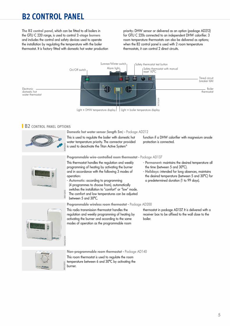
The B2 control panel, which can be fitted to all boilers in the GTU C 220 range, is used to control 2-stage burners and includes the control and safety devices used to operate the installation by regulating the temperature with the boiler thermostat. It is factory fitted with domestic hot water production
priority: DHW sensor or delivered as an option (package AD212) for GTU C 220s connected to an independent DHW calorifier. 3 room temperature thermostats can also be delivered as options; when the B2 control panel is used with 2 room temperature thermostats, it can control 2 direct circuits.
Alarm lightOn/Off switch
Light + boiler temperature displayLight + DHW temperature display
Summer/Winter switch Safety thermostat test button Safety thermostat with manual reset 110°C
Timed circuit breaker (6A)
Electronic domestic hot water thermostat
Boiler thermostat
8575
Q01
9
B2 CONTROL PANEL OPTIONS
8518
Q02
2
Domestic hot water sensor (length 5m) - Package AD212This is used to regulate the boiler with domestic hot water temperature priority. The connector provided is used to deactivate the Titan Active System®
function if a DHW calorifier with magnesium anode protection is connected.
8801
Q00
2
Programmable wire-controlled room thermostat - Package AD137This thermostat handles the regulation and weekly programming of heating by activating the burner and in accordance with the following 3 modes of operation: - Automatic: according to programming
(4 programmes to choose from), automatically switches the installation to “comfort” or “low” mode. The comfort and low temperatures can be adjusted between 5 and 30°C.
- Permanent: maintains the desired temperature all the time (between 5 and 30°C).
- Holidays: intended for long absences, maintains the desired temperature (between 5 and 30°C) for a predetermined duration (1 to 99 days).
8666
Q12
0A
Programmable wireless room thermostat - Package AD200This radio transmission thermostat handles the regulation and weekly programming of heating by activating the burner and according to the same modes of operation as the programmable room
thermostat in package AD137. It is delivered with a receiver box to be affixed to the wall close to the boiler.
8801
Q00
3
Non-programmable room thermostat - Package AD140This room thermostat is used to regulate the room temperature between 6 and 30°C by activating the burner.
6
D + AD217: DIEMATIC 3 CONTROL PANEL WITH AD217 ADDITIONAL PACKAGE
0 2 4 6 8 10 12 14 16 18 20 22 24
B
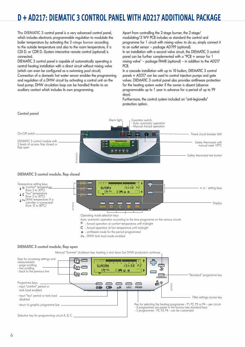
The DIEMATIC 3 control panel is a very advanced control panel, which includes electronic programmable regulation to modulate the boiler temperature by activating the 2-stage burner according to the outside temperature and also to the room temperature, if a CDI D. or CDR D. iSystem interactive remote control (optional) is connected.DIEMATIC 3 control panel is capable of automatically operating a central heating installation with a direct circuit without mixing valve (which can even be configured as a swimming pool circuit).Connection of a domestic hot water sensor enables the programming and regulation of a DHW circuit by activating a control unit on the load pump; DHW circulation loop can be handled thanks to an auxiliary contact which includes its own programming.
Apart from controlling the 2-stage burner, the 2-stage/modulating/3 WV PCB includes as standard the control and programme for 1 circuit with mixing valve: to do so, simply connect it to an outlet sensor – package AD199 (optional).In an installation with a second valve circuit, the DIEMATIC 3 control panel can be further complemented with a “PCB + sensor for 1 mixing valve” – package FM48 (optional) – in addition to the AD217 PCB.In a cascade installation with up to 10 boilers, DIEMATIC 3 control panels + AD217 can be used to control injection pumps and gate valves. DIEMATIC 3 control panel also provides antifreeze protection for the heating system water if the owner is absent (absence programmable up to 1 year in advance for a period of up to 99 days).Furthermore, the control system included an “anti-legionella” protection option.
DIEMATIC 3 control module, flap closed
Temperature setting keys:- “comfort” temperature
(from 5 to 30°C)- “low” temperature
(from 5 to 30°C)- DHW temperature (if a
calorifier is connected) (from 10 to 80°C)
+ or - setting keys
Operating mode selection keysAuto: automatic operation according to the time programme on the various circuits
: forced operation at comfort temperature until midnight : forced operation at low temperature until midnight : antifreeze mode for the period programmed : DHW tank load mode enabled
Display
8575
F020
On/Off switch
Alarm light 2-position switch:- Auto: automatic operation- Manual: forced operation
DIEMATIC 3 control module with 2 levels of access: flap closed or flap open
Timed circuit breaker (6A)
Safety thermostat with manual reset 110°C
Safety thermostat test button
8575
Q02
2A
Control panel
DIEMATIC 3 control module, flap open
STANDARD
A.B.C PROGR
0 2 4 6 8 10 12 14 16 18 20 22 24
B
Keys for accessing settings and measurements- page scrolling- line scrolling- back to the previous line
Programme keys:- input “comfort” period or
tank load enabled
- input “low” period or tank load disabled
- return to graphic programme bar
Manual “Summer“ shutdown key: heating is shut down but DHW production continues
“Standard” programme key
Key for selecting the heating programme - P1, P2, P3 or P4 – per circuit:- 4 programmes are preset in the factory (see standard key).- 3 programmes - P2, P3, P4 - can be customised
Fitter settings access key
Selection key for programming circuit A, B, C
8575
F021

7
D + AD217: DIEMATIC 3 CONTROL PANEL WITH AD217 ADDITIONAL PACKAGE
OPTIONS FOR DIEMATIC 3 CONTROL PANEL WITH AD217 ADDITIONAL PACKAGE
8518
Q02
2G
T220
_Q00
02
Domestic hot water sensor (length 5m) - Package AD212
Outlet sensor downstream of the valve (length 2.5m) - Package AD199
This is used to regulate the boiler with domestic hot water temperature priority.
The connector provided is used to deactivate the Titan Active System® function if a DHW calorifier with magnesium anode protection is connected.
This sensor is required if using the “2 stage/modulating/3WV PCB” for controlling the first circuit with mixing valve.
8575
Q03
6G
T220
_Q00
01
PCB + sensor for 1 mixing valve - Package FM48
2 stage/mod./3WV PCB - Package AD217
This is used to control a 2nd mixing valve with a two-direction electrothermal or electromechanical motor. The valve circuit and its circulating pump can be programmed independently.
Note: DIEMATIC 3 control panels with AD217 PCB can be fitted with 1 outlet sensor downstream of the valve (package AD199) + 1 PCB + sensor option for 1 mixing valve.
This PCB is used to control a GTU C 220 boiler fitted with a 2-stage or modulating burner. It is delivered as standard with GTU C 220 boilers + AD217.
It also includes control and programming of a circuit with a 3-way mixing valve; the outlet sensor downstream of the valve (package AD199) must be ordered separately, however.
8666
Q17
2A
CDI D. iSystem interactive remote control - Package AD285CDR D. iSystem interactive remote “radio” control (without radio transmitter) - Package AD284Boiler “radio” control module (radio transmitter) - Package AD252These are used to override all instructions from the DIEMATIC 3 control panel from the room in which they are installed. In addition, they enable the self-adaptability of the heating regime for the circuit concerned (one CDI D. or CDR D. iSystem per circuit).
In the case of the CDR D. iSystem, the data are transmitted by radio waves from the place where the CDR D. iSystem is installed to the transmitter/receiver box placed close to the boiler.
AD284/285
AD252
8575
Q03
7
Simplified remote control with room sensor - Package FM52The connection of a simplified remote control is used to override certain instructions from the DIEMATIC 3 control panel from the room in which it is installed: programme override (permanent comfort or low)
and set room temperature override (± 3.5°C). It is also used to enable the self-adaptability of the heating curve for the circuit concerned (1 remote control per circuit).
Radio outside temperature sensor - Package AD251Boiler radio module (radio transmitter) - Package AD252The radio outside temperature sensor can be delivered as optional equipment for systems in which the installation of the external wire connection sensor delivered with DIEMATIC 3 control panels would be too complex. If this sensor is used:
- With a wire connection remote control (AD285 or FM52), it is necessary to order the “Boiler radio module” as well
- With a radio remote control (AD284), ordering a 2nd “Boiler radio module” is not necessary
8227
Q02
0
BUS connecting cable (length 12 m) - Package AD134It is used to make the connection between 2 boilers fitted with the DIEMATIC 3 control panel in a
cascade installation, or to connect a DIEMATIC VM iSystem control unit.
8666
Q17
2A85
75Q
034
AD251
AD252
8575
Q04
8
Flue gas sensor - Package FM47This enables the user to read the display on the flue gas temperature table and control the state of cleanliness of the heating exchange surfaces in the
heating body. In the case of cascade installations, each of the boilers can be connected to a flue gas sensor.
CA
LEN
TA_Q
0005

8
D + AD217: DIEMATIC 3 CONTROL PANEL WITH AD217 ADDITIONAL PACKAGE
OPTIONS FOR DIEMATIC 3 CONTROL PANEL WITH AD217 ADDITIONAL PACKAGE
8531
Q01
388
01Q
018
Sensors for buffer tank - Package AD160
Dip sensor with tube - Package AD218
Includes 1 DHW sensor and 1 heating sensor for managing a buffer tank with a boiler fitted with a DIEMATIC 3 control panel.
This dip sensor (NTC 147) is delivered with an IP 54 junction box and a 1/2” sensor tube, length under head 120 mm. It is used instead of the attachable
sensors provided with the PCB and valve options. It can also be used on the header pipe when connecting 2 boilers in cascade.
BOILER OPTIONS
Domestic hot water productionDe Dietrich B… series independent hot water tanks with a capacity of 150 to 3000 litres can be used for domestic hot water production for individual and collective dwellings as well as for industrial and commercial premises. They are lined with
food quality standard high quartz content vitrified enamel and protected by a magnesium anode. The specifications and performances of these tanks are given in the various technical leaflets.
BPB_
Q00
01A
BPB…
RSB_
Q00
04A
BLC
_Q00
01A
B…BLC…
BPB/BLC…, UNO and TRIO calorifier/boiler connection kit - Package EA117As a general rule, the DHW calorifier can be placed to the right or left of the boiler according to the details given in the technical instructions for the boiler. The connection kits include an air vent, a non-return valve, a load pump and all the pipes required to make the connection.
Attention: do not forget to order the DHW sensor, package AD212.
DTG
130_
Q00
15
Condensates neutralization box - Package ME115Refill carbon filter and marble granules for neutralization box ME115 - Package ME116Lift pump for neutralization box - Package FM158This neutralisation box comes with a carbon and marble granule filter.The flow of condensates between the boiler and the neutralisation box must be by gravity. The condensates resulting from the combustion of oil are acidic (pH 2). Installation of a condensates neutralisation box before discharge into the wastewater network is strongly recommended. During annual maintenance operations, the efficiency of the granules must be checked by measuring the pH: replacement of the carbon filter and the granules is necessary if the pH is lower than 6.5.
Specifications of the lift pump(Package FM158)
Flow (L/min)
Man
omet
ric h
eigh
t (m
)
00
1
2
3
4
5
1 2 3 4 5
GTU
C12
0_F0
007A
GTU
C22
0_Q
0007
ME115
GTU
C22
0_Q
0008
GTU
C22
0_Q
0008
ME116
FM158
Second return set (pump included) - Package ME117
GTU
C22
0_Q
0010
9
1065
520
0,5m
0,5m
0,5m
0,5mL
1m1m
1m1m
INFORMATION REQUIRED FOR INSTALLATION
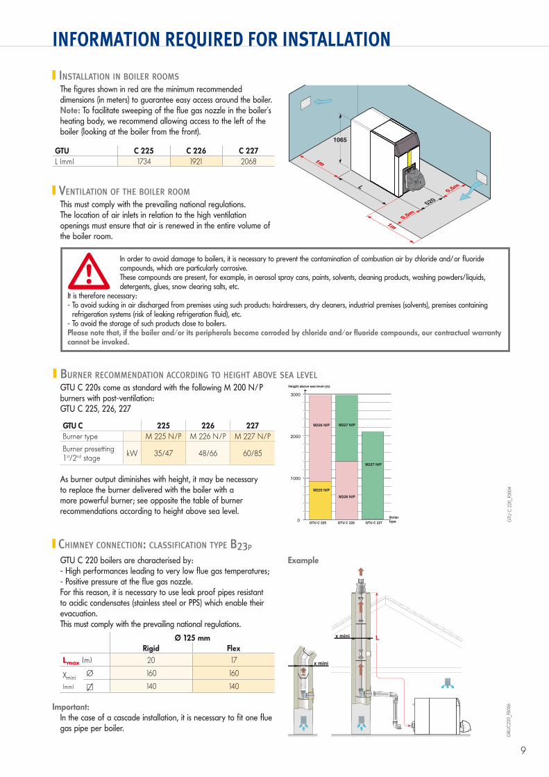
INSTALLATION IN BOILER ROOMS
BURNER RECOMMENDATION ACCORDING TO HEIGHT ABOVE SEA LEVELGTU C 220s come as standard with the following M 200 N/P burners with post-ventilation:GTU C 225, 226, 227
GTU C 225 226 227Burner type M 225 N/P M 226 N/P M 227 N/P
Burner presetting 1st/2nd stage kW 35/47 48/66 60/85
1000
0
2000
3000
GTU C 225
M226 N/P
M226 N/P
M227 N/P
M227 N/P
M225 N/P
GTU C 226 GTU C 227
Height above sea level (m)
Boiler
type GTU
C 2
20_F
0004
As burner output diminishes with height, it may be necessary to replace the burner delivered with the boiler with a more powerful burner; see opposite the table of burner recommendations according to height above sea level.
The figures shown in red are the minimum recommended dimensions (in meters) to guarantee easy access around the boiler.Note: To facilitate sweeping of the flue gas nozzle in the boiler’s heating body, we recommend allowing access to the left of the boiler (looking at the boiler from the front).
GTU C 225 C 226 C 227L (mm) 1734 1921 2068
In order to avoid damage to boilers, it is necessary to prevent the contamination of combustion air by chloride and/or fluoride compounds, which are particularly corrosive.These compounds are present, for example, in aerosol spray cans, paints, solvents, cleaning products, washing powders/liquids, detergents, glues, snow clearing salts, etc.
It is therefore necessary:- To avoid sucking in air discharged from premises using such products: hairdressers, dry cleaners, industrial premises (solvents), premises containing
refrigeration systems (risk of leaking refrigeration fluid), etc.- To avoid the storage of such products close to boilers.Please note that, if the boiler and/or its peripherals become corroded by chloride and/or fluoride compounds, our contractual warranty cannot be invoked.
VENTILATION OF THE BOILER ROOMThis must comply with the prevailing national regulations.The location of air inlets in relation to the high ventilation openings must ensure that air is renewed in the entire volume of the boiler room.
CHIMNEY CONNECTION: CLASSIFICATION TYPE B23P
GTU C 220 boilers are characterised by:- High performances leading to very low flue gas temperatures;- Positive pressure at the flue gas nozzle.For this reason, it is necessary to use leak proof pipes resistant to acidic condensates (stainless steel or PPS) which enable their evacuation.This must comply with the prevailing national regulations.
Important:In the case of a cascade installation, it is necessary to fit one flue gas pipe per boiler.
GRU
C22
0_F0
006
Ø 125 mmRigid Flex
Lmax (m) 20 17
Xmini(mm)
Ø 160 160
�/ 140 140
Example
10
INFORMATION REQUIRED FOR INSTALLATION
EXAMPLES OF INSTALLATIONS
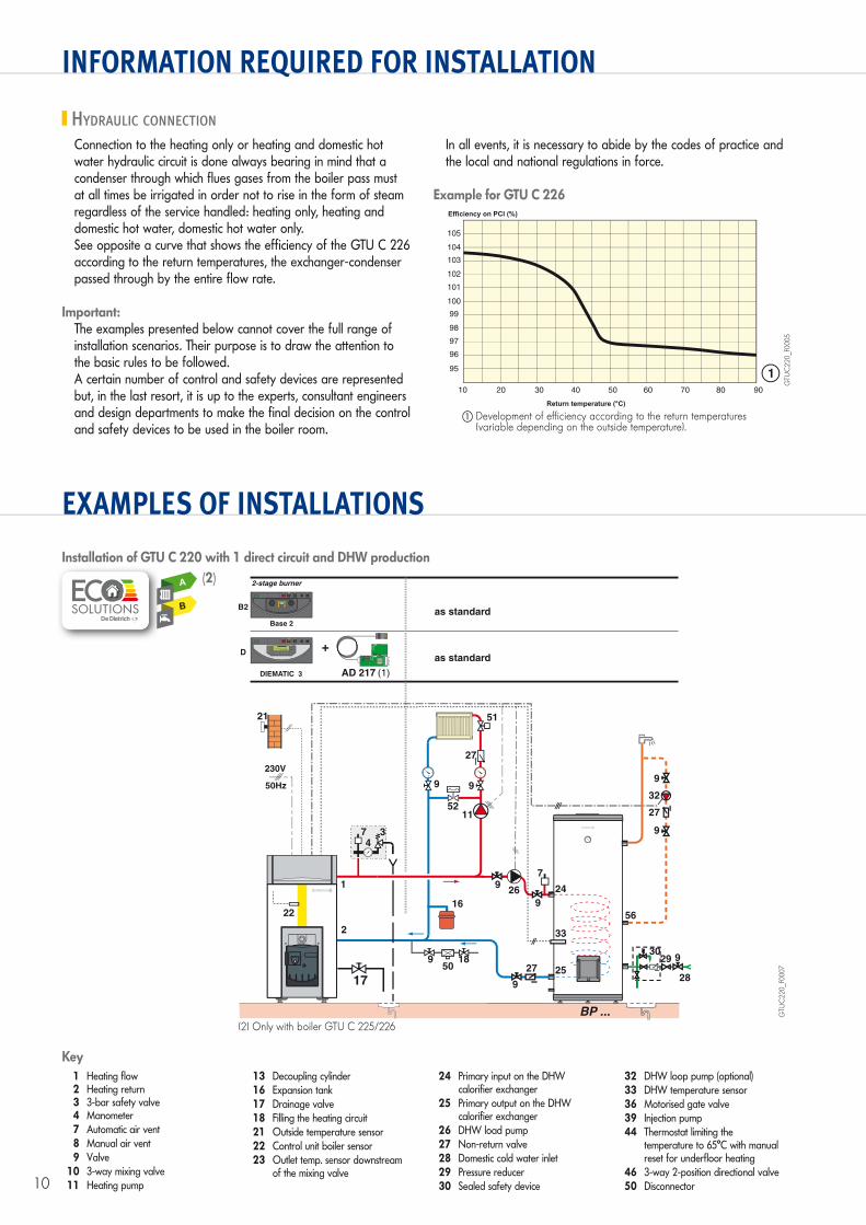
HYDRAULIC CONNECTION
Connection to the heating only or heating and domestic hot water hydraulic circuit is done always bearing in mind that a condenser through which flues gases from the boiler pass must at all times be irrigated in order not to rise in the form of steam regardless of the service handled: heating only, heating and domestic hot water, domestic hot water only.See opposite a curve that shows the efficiency of the GTU C 226 according to the return temperatures, the exchanger-condenser passed through by the entire flow rate.
Important:The examples presented below cannot cover the full range of installation scenarios. Their purpose is to draw the attention to the basic rules to be followed.A certain number of control and safety devices are represented but, in the last resort, it is up to the experts, consultant engineers and design departments to make the final decision on the control and safety devices to be used in the boiler room.
In all events, it is necessary to abide by the codes of practice and the local and national regulations in force.
Example for GTU C 226
GTU
C22
0_F0
005
� Development of efficiency according to the return temperatures (variable depending on the outside temperature).
10
105
104
103
102
101
100
99
97
96
98
95
Return temperature (°C)
20 30 40 50 60 70 80 90
1
Efficiency on PCI (%)
Installation of GTU C 220 with 1 direct circuit and DHW production
0
I
4A
4 5
6
7
81
2
3
3
4
5
6
7
8
9B2Base 2
17
0
I
4A
0 2 4 6 8 10 12 14 16 18 20 22 24
D
DIEMATIC 3
MERCREDI 15h38
2-stage burner
50189
16
2
21
50Hz
230V
as standard
as standard
AD 217 (1)
22
1
51
99
5211
27
C C
34
7
56
33
24
25
BP ...
9
32
27
9
27
7
9
9
9
28
29 930
TS
N
26
GTU
C22
0_F0
007
1 Heating flow 2 Heating return 3 3-bar safety valve 4 Manometer 7 Automatic air vent 8 Manual air vent 9 Valve 10 3-way mixing valve 11 Heating pump
13 Decoupling cylinder 16 Expansion tank 17 Drainage valve 18 Filling the heating circuit 21 Outside temperature sensor 22 Control unit boiler sensor 23 Outlet temp. sensor downstream
of the mixing valve
24 Primary input on the DHW calorifier exchanger
25 Primary output on the DHW calorifier exchanger
26 DHW load pump 27 Non-return valve 28 Domestic cold water inlet 29 Pressure reducer 30 Sealed safety device
32 DHW loop pump (optional) 33 DHW temperature sensor 36 Motorised gate valve 39 Injection pump 44 Thermostat limiting the
temperature to 65°C with manual reset for underfloor heating
46 3-way 2-position directional valve 50 Disconnector
Key
(2) Only with boiler GTU C 225/226
(2)
B
A
11
EXAMPLES OF INSTALLATIONS
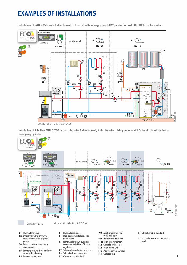
Installation of GTU C 220 with 1 direct circuit + 1 circuit with mixing valve. DHW production with DIETRISOL solar system
89
99
26
65
99
5211
10
27
C C
23
44
4 109
131
130 87
88
126
114
46
8461
85
4
112b
29 30
329
9
27
90 7
230V50HzSET
Dietrisol B
<>
33
24
56
25
81
112a
50
18916
2
21
50Hz
230V
22 1
51
99
5211
27
C C
3
4
7
as standard
AD 212AD 217 AD 199(1)
TS
N
17
0
I
4A
0 2 4 6 8 10 12 14 16 18 20 22 24
DIEMATIC 3
MERCREDI 15h38
GTU
C22
0_F0
008
Installation of 2 boilers GTU C 220 in cascade, with 1 direct circuit, 4 circuits with mixing valve and 1 DHW circuit, all behind a decoupling cylinder
29
30
28
9
7
33
24
25
329
9
27
27
26
9 9
65
99
5211
10
2727
27 27 27 27 27
C C
23
44
4
C C
4
C C
4
C C
4
50
189
DIEMATIC 3
0
I
4A
0 2 4 6 8 10 12 14 16 18 20 22 24
MERCREDI 15h38
DIEMATIC 3
0
I
4A
0 2 4 6 8 10 12 14 16 18 20 22 24
MERCREDI 15h38
17 36 36
39 39
16
7
8
13
17
AD199
FM48
TS
N L
FM48
TS
N L
65
99
5211
10
27
23
4465
99
5211
10
27
23
4465
99
5211
10
27
23
44
21
9
34
1
7
Cable BUS AD134
2
22 9
34
1
7
2
22
51
99
5211
C C
AD 217 AD 217 AD 199
as standard
AD 212
123
AD 218
230 V
single-phase
curren
230 V single-phase curren
(1) (1)
TS
N
TS
N
GTU
C22
0_F0
009
“Secondary” boiler
51 Thermostatic valve 52 Differential valve (only with
module fitted with a 3-speed pump)
56 DHW circulation loop return 61 Thermometer 65 Low temperature circuit (radiator
or underfloor heating) 75 Domestic water pump
81 Electrical resistance 84 Stop cock with unlockable non-
return valve 85 Primary solar circuit pump (for
connection to DIEMASOL solar regulation)
87 Safety valve calibrated to 6 bars 88 Solar circuit expansion tank 89 Container for solar fluid
90 Antithermosiphon lyre (= 10 x Ø pipe)
109 Thermostatic mixer tap 112a Solar collector sensor 123 Cascade outlet sensor 126 Solar control unit 130 Manual air vent (Airstop) 131 Collector field
(1) PCB delivered as standard
� no outside sensor with B2 control panels
(2) Only with boiler GTU C 225/226
(2)D
D
A
(2) Only with boiler GTU C 225/226
(2)
B
A

DE DIETRICH THERMIQUES.A.S. with corporate capital of 22 487 610 €57, rue de la Gare - F-67580 MERTZWILLERTel. +33 3 88 80 27 00 - Fax +33 3 88 80 27 99www.dedietrich-heating.com
09/2
016
– 30
0028
927A
– 3
47.5
55.5
59 S
trasb
ourg
Com
pani
es R
egist
er –
Doc
umen
t not
con
tract
ually
bin
ding
- Pr
inte
d in
Fra
nce
- OTT
Impr
imeu
rs 6
7310
Was
selo
nne
- 162
307
DESCRIPTION
GTU C 220OIL-FIRED CONDENSING BOILER
Model GTU C 22..Useful output range (80/60°): ___ kWUseful output range (50/30°): ___ kWBoiler + condenser water content: ___ litresOperating pressure: 3 barMax. temperature: 90°CMaximum pressure at the nozzle: ___ mbarFloor space required: ___ (L) x ___ (W) mmNumber of sections (boiler): ___Weight empty: ___ kg
Equipment: Low NOx oil burner with post-ventilation.Ø flue nozzle: 125 mmØ boiler flow/return: 1 1/4”
The boilers will be delivered as an assembled body tested in the factory or, on request, in separate sections to be assembled in situ. The condensing unit composed of the ceramic condenser with the siphon, the casing, the burner and the accessories, is delivered in separate packaging.
The condensing generator is composed of:Boiler
- Low temperature boiler with main heating body in Eutectic cast iron with pressurised humid combustion chamber with integral 3-path flue gas discharge.
- Cast iron baffles are fitted as standard to all emissions flues- Full insulation of the heating body with glass-wool covered on
both sides with a protective fabric - Flue gas circuit tightness guaranteed by very thick woven
silicone cord - Water circuit tightness guaranteed by bi-spherical nipples - Reversible burner door (opens to the right or left) with thick
insulation - Casing in steel coated on both sides with kiln-baked epoxy
polyester paint - Maintenance of the boiler is facilitated by:
• A hinged door for sweeping • Detachable baffles • A flue gas channel design that allows the use of a suction
nozzle
Burner- 2-stage oil burner with post-ventilation and low pollution
emissions (NOx < 100 mg/kWh at 50-30°C), tested and preset while hot, delivered with 2 supply hoses
Condenser• Condensing heat exchanger on the flue gases with exchange
surfaces in ceramic piping fitted with inspection hatches.- Large capacity condensates evacuation siphon integrated under
the condenser inside the boiler casing.- Adjustable feet
Choice of 2 control panels- B2 control panel: used to control a direct circuit and a
domestic hot water circuit (DHW sensor optional).- DIEMATIC 3 control panel + AD217: Control system
programmable according to the outside temperature, with integrated digital display in the boiler control panel.
Principles of the DIEMATIC 3 control panel:The control, monitoring and regulation of the heating equipment will be provided by a regulator enabling control of:- The 2-stage boiler
- 1 independently programmable, domestic, accumulating or semi-accumulating, domestic hot water tank
- 1 swimming pool circuit or a second DHW production circuit- 1 domestic hot water loop pump- 1 to 2 low temperature circuits controlled by an independently
programmable mixing valve- Cascades comprising up to 10 boilersIf the house is empty, antifreeze protection of the installation and the room temperature is provided. Characteristics:Digital controller with displays in plain English (no codes)Menu scrolling in both directionsDay and night set point controls, heating curves allowing parallel shifts by direct touch, without needing to enter the scrolling menu.Electrical connection of the burner by pin connector cable. The control panel is delivered with electromechanical equipment for the control panel, which can take priority over the control system (manual operation)
Boiler options- Condensates neutralisation system- Boiler/DHW tank connecting kit
B2 control panel options- Non-programmable room temperature thermostat - Programmable room temperature thermostat connected by wire - Programmable room temperature thermostat with wireless
connection - DHW sensor
DIEMATIC 3 control panel + AD217 options- Flow sensor downstream of the valve- Domestic hot water sensor- Dip flow sensor + sensor tube- PCB + sensor for 1 mixing valve- Flue gas temperature sensor- Remote control with room temperature sensor - Interactive wire- or radio-controlled remote control - Outside radio-controlled sensor- Boiler radio module (transmitter/receiver)- Connecting cable length 40 m for wall support- BUS cable extension
DESCRIPTON