technical reference · the lucent technologies 5ess, the siemens ewsd, and the nortel dms-100...
TRANSCRIPT

TR 50010
TECHNICALREFERENCE
AT&T ISDN
BASIC RATE INTERFACE
REFERENCE GUIDE
Issue 2.1December 1997

AT&T TECHNICAL REFERENCE 50010ISSUE 2.1 DECEMBER 1997
i
NOTICE
This Technical Reference is published by AT&T as a guide for the designers, developers,manufactures, consultants, suppliers and others of systems and equipment which would meet thedescribed interface. AT&T reserves the right to revise this Technical Reference for any reason,including, but not limited to, conformity with standards promulgated by ANSI, EIA, ITU-T(formerly CCITT), ISO or similar agencies, use of new advances in the state of technical arts, or toreflect changes in the requirements of communication systems or equipment. Liability fordifficulties arising from technical limitations is disclaimed. AT&T makes no claims andrepresentations and assumes no responsibilities beyond those set forth in the applicable tariffs.
No license under AT&T’s intellectual property rights (including, in particular, patents andcopyrights) or intellectual property rights of others are provided by the furnishing of thisdocument, nor does the furnishing of this document indicate that the use of any informationcontained in it will be free of infringement of any intellectual property rights.
The provisions of planned network capabilities as described in this document requires certainbusiness decisions and regulatory agency approvals. Note that, as of the date of publication of thisdocument, many of these business decisions may not have been made nor regulatory approvalreceived or requested.
Specifications contained in this document are current as of the date of this publication. They maybe superseded by information published in related AT&T Technical References and subject to theeffective date of these publications. All AT&T Technical References are subject to change, andtheir citation in this document reflects the most current information available at the time ofprinting.
No part of this publication may be reproduced or distributed in any form or by any means withoutthe prior written permission of AT&T.
If further information is required, please Contact:
Developmental Relations GroupRoom 5356C3295 N. Maple AvenueBasking Ridge, NJ 07920
To order copies of this document:
Call: AT&T Customer Information CenterUSA: (800) 432-6600EUROPE: 010-1-317-322-6416FAR EAST: 010-1-317-322-6389AMERICAS/MID EAST/AFRICA: 010-1-317-322-6646
Write: AT&T Customer Information Center2855 North Franklin RoadP.O. Box 19901Indianapolis, IN 46219
For more information about AT&T documents, see:
CATALOG OF COMMUNICATIONS TECHNICAL PUBLICATIONS
Publications Catalog (10000)
AT&T TECHNICAL REFERENCE 50010ISSUE 2.1 DECEMBER 1997
ii
AT&T ISDN BASIC RATE INTERFACE REFERENCE GUIDE
ISSUE 2.1
December 1997
TABLE OF CONTENTS
1. INTRODUCTION 1
2. BRI CENTRAL OFFICE SWITCH IMPLEMENTATION 1
2.1 Physical Layer 1
2.2 Data Link Layer 2
2.3 Network Layer 2
2.3.1 Service Differentiators 2
2.3.1.1 Lucent Technologies 3
2.3.1.2 Northern Telecom 3
2.3.1.3 Siemens Stromberg-Carlson 3
3. REFERENCE CO SWITCH SPECIFICATIONS 3
GLOSSARY 5
LIST OF TABLES
Table 1. Bellcore’s NI Special Reports - Primary Drivers of Layer 3......................................................2Table 2. ISDN BRI Specifications ..........................................................................................................4Table 3. Profile and Ordering Information .............................................................................................4
AT&T TECHNICAL REFERENCE 50010ISSUE 2.1 DECEMBER 1997
1
1. INTRODUCTION
This Technical Reference (TR) is provided to support AT&T’s digital services over Integrated ServicesDigital Network (ISDN) Basic Rate Interface (BRI). The intent of the document is to be a reference guideto BRI terminal developers who will provide customer premises equipment (CPE) in support of AT&Tdigital services. This document directs BRI terminal equipment developers to the specification of eachISDN BRI central office switch under consideration and provides in Appendix 1 recommended networktermination (NT) device enhancements to facilitate end-to-end maintenance of ISDN BRI based services.
This document updates and replaces in its entirety AT&T Technical Reference TR50010, dated September1996. The major change/addition contained in this document is the addition of Appendix 1. Thisdocument also updates and replaces in its entirety AT&T Technical Reference TR50010, Issue 2 datedOctober, 1997. The changes contained in this document are described in the Introduction Section ofAppendix 1. There is no change to the TR with regard to references on BRI central office switchspecifications.
The information in the main body of this technical reference directs BRI terminal developers to thespecification of each central office switch under consideration. The TR currently focuses on CO switchesmanufactured by Lucent Technologies (formerly AT&T), Northern Telecom, and Siemens Stromberg-Carlson. Respectively, these switches are the 5ESS, DMS-100, and EWSD. It is not the intent ofthis section of the document to provide new or updated information over and above that provided in eachof the referenced specifications.
In each instance the referenced specification defines the requirements for the Physical Layer (Layer 1),the Data Link Layer (Layer 2) , and the Network Layer (Layer 3). All specifications adhere to the ITU-TS (formerly CCITT) definition of a Basic Rate Interface. As such, the interface is defined as a bi-directional 144 Kbps digital subscriber loop segmented such that there are two 64-Kbps B-channels andone 16-Kbps D-channel. The B-channels transport user voice and/or data while the D-channeltransports signaling and packet data.
The BRI central office switch specifications have their basis in the CCITT ISDN Recommendations,Series I , Q, and X, the Bellcore TRs and SRs, and the ANSI T1 Standards. Each specificationrepresents the switch manufacturer’s interpretation and subsequent implementation of the standards. Asthe interpretations are not unique, and as manufacturers wish to provide service differentiators, there aresome variations in the realization of the interface and the type of services provided.
2. BRI CENTRAL OFFICE SWITCH IMPLEMENTATION
2.1 Physical Layer
The maturity of the standards and the industry’s experience with the Layer 1 portion of the interface issuch that there is little variation in implementation across the switches. The U and S/T referencepoints are supported in all cases. For the U reference point the implementations are consistent with ANSIT1.601-1991. At the S/T reference point, ANSI T1.605-1991 and ITU-TS Recommendation I.430 areadhered to.

AT&T TECHNICAL REFERENCE 50010ISSUE 2.1 DECEMBER 1997
2
2.2 Data Link Layer
As in the case of the Physical Layer, there is little variation in implementation of Layer 2 across theswitches. The implementations are consistent with ITU-TS Recommendations Q.920 (I.440) and Q.921(I.441), and with ANSI T1.602-1988. All support point-to-point and broadcast data links, modulo 128operation, and manual and automatic Terminal Endpoint Identifier (TEI) assignment.
The 5ESS, in addition, supports two LAPD extensions that are not covered in the ITU-TSRecommendations, exchange identification (XID) audit and parameter notification. Multiple D-channelsignaling and packet links also are supported on the 5ESS.
2.3 Network Layer
The Bellcore TRs and SRs are the primary drivers of the specifications at Layer 3. By committing tosupport National ISDN the switch vendors have agreed to develop interfaces that are consistent withNational ISDN-1 (NI-1), NI-2, and NI-31. The realization of these National ISDN offerings has had thegreatest impact on the CO switches at Layer 3. Modification of the protocol, feature interaction, andservice offering to the end-user has had to occur at this layer in the transition from proprietary (custom)ISDN to National ISDN. The specifications are fully self-contained. However, it may be beneficial tohave the Bellcore documents in Table 1 available.
DocumentNumber
Service Title
SR-NWT-001953 NI-1 Generic Guidelines for ISDN Terminal Equipment on Basic AccessInterfaces
SR-NWT-002120 NI-2 Generic Guidelines for National ISDN 2 Basic Access Interfaces
SR-NWT-002457 NI-3 Generic Guidelines for National ISDN 3 Basic Access Interfaces
Table 1. Bellcore’s NI Special Reports - Primary Drivers of Layer 3
The Lucent Technologies 5ESS, the Siemens EWSD, and the Nortel DMS-100 support NI-1, NI-2, andNI-3.
2.3.1 Service Differentiators
The switch vendors are able to differentiate their BRI service offering at this layer. Basic Call Control,the big four Supplementary Services (HCDT - Hold, Conference, Drop, and Transfer) and a number ofthe NI-3 features have been implemented by the switch vendors. However, the vendors have
1 Recall that NI-1 defines the protocol at the user-network interface (UNI) with little attention to feature operation on the different vendorswitches. In NI-2 , the feature operations are standardized across the switches. NI-3 then defines a minimum set of features to beoffered at the UNI by all the switch vendors.
AT&T TECHNICAL REFERENCE 50010ISSUE 2.1 DECEMBER 1997
3
distinguished their service offering by providing enhancements to the Supplementary Services or byproviding value-added features not defined in NI-3.
2.3.1.1 Lucent Technologies
The 5ESS provides additional services in the following Supplementary Services areas: Non-InitializingTerminals (NITs), Supplementary Data Services, and Personal Communication Services (PCS)/ISDNinterworking.
2.3.1.2 Northern Telecom
The DMS-100 provides additional services in the following Supplementary Services areas: Call Park,Call Request, Ring Again (Automatic Call Back), Key Short Hunt, Loudspeaker and Radio PagingAccess, and Release. Additionally, the DMS-100 facilitates manual and terminal backwardcompatibility automatic (via D-channel signaling) through the use of Protocol Version Control (PVC).
2.3.1.3 Siemens Stromberg-Carlson
The EWSD provides additional services in the following Supplementary Services area: PCS/ISDNinterworking.
3. REFERENCE CO SWITCH SPECIFICATIONS
The subsequent listing of specifications are for those switches over which AT&T could potentially supportISDN BRI service. In general, these interfaces are under consideration as they are currently the mostwidely deployed throughout the regions. In each case some degree of backward compatibility isindicated. Generics earlier than those represented are not discussed as support for them is limited or non-existent. For information on the earlier generics contact each vendor at the number provided.
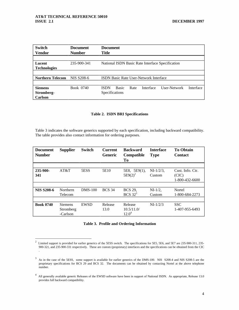
Table 2 designates each vendor and their corresponding ISDN BRI specification document number. It isrecommended that the document number and not the title be used when ordering the specifications.
AT&T TECHNICAL REFERENCE 50010ISSUE 2.1 DECEMBER 1997
4
SwitchVendor
DocumentNumber
DocumentTitle
LucentTechnologies
235-900-341 National ISDN Basic Rate Interface Specification
Northern Telecom NIS S208-6 ISDN Basic Rate User-Network Interface
SiemensStromberg-Carlson
Book 0740 ISDN Basic Rate Interface User-Network InterfaceSpecifications
Table 2. ISDN BRI Specifications
Table 3 indicates the software generics supported by each specification, including backward compatibility.The table provides also contact information for ordering purposes.
DocumentNumber
Supplier Switch CurrentGeneric
BackwardCompatibleTo
InterfaceType
To ObtainContact
235-900-341
AT&T 5ESS 5E10 5E8, 5E9(1),5E9(2)2
NI-1/2/3,Custom
Cust. Info. Ctr.(CIC)1-800-432-6600
NIS S208-6 NorthernTelecom
DMS-100 BCS 34 BCS 29,BCS 323
NI-1/2,Custom
Nortel1-800-684-2273
Book 0740 SiemensStromberg-Carlson
EWSD Release13.0
Release10.5/11.0/12.04
NI-1/2/3 SSC1-407-955-6493
Table 3. Profile and Ordering Information
2 Limited support is provided for earlier generics of the 5ESS switch. The specifications for 5E5, 5E6, and 5E7 are 235-900-311, 235-
900-321, and 235-900-331 respectively. These are custom (proprietary) interfaces and the specifications can be obtained from the CIC.
3 As in the case of the 5ESS, some support is available for earlier generics of the DMS-100. NIS S208-4 and NIS S208-5 are the
proprietary specifications for BCS 29 and BCS 32. The documents can be obtained by contacting Nortel at the above telephonenumber.
4 All generally available generic Releases of the EWSD software have been in support of National ISDN. As appropriate, Release 13.0
provides full backward compatibility.

AT&T TECHNICAL REFERENCE 50010ISSUE 2.1 DECEMBER 1997
5
GLOSSARY
ANSI American National Standards InstituteBRI Basic Rate InterfaceCO Central OfficeCPE Customer Premises EquipmentISDN Integrated Services Digital NetworkITU-TS International Telecommunication Union - Telecommunication SectionLAPD Link Access Protocol for D-channelNI National ISDNNIT Non-Initializing TerminalPCS Personal Communication ServicesPVC Protocol Version ControlTEI Terminal Endpoint IdentifierTR Technical ReferenceXID Exchange Identification
TR 50010
TECHNICALREFERENCE
AT&T ISDN BASIC RATE INTERFACE
REFERENCE GUIDE
Appendix 1
RECOMMENDED NT DEVICE
ENHANCEMENTS TO FACILITATE
END-TO-END MAINTENANCE OF ISDN
Issue 2.1December 1997
AT&T TECHNICAL REFERENCE 50010 APPENDIX 1ISSUE 2.1 DECEMBER 1997
i
AT&T ISDN BASIC RATE INTERFACE REFERENCE GUIDE
Appendix 1
RECOMMENDED NT DEVICE ENHANCEMENTS TO FACILITATE
END-TO-END MAINTENANCE OF ISDN
Issue 2.1December 1997
TABLE OF CONTENTS
1. INTRODUCTION 1
2. SCOPE 1
3. DEFINITIONS 1
4. ENHANCED MODE OF OPERATION 2
4.1 Definition of Normal and Enhanced Modes of Operation 2
4.2 Enhanced Mode Phases 24.2.1 Enhanced Function Request 34.2.2 Enhanced Function Activation 54.2.3 Enhanced Function Operation 64.2.4 Enhanced Function De-Activation 7
4.3 Transmission of Diagnostic Data 84.3.1 Diagnostic Data Frame 84.3.2 End-of-Message Diagnostic Data Frame 94.3.3 Diagnostic Data Transmission Procedures 9
5. ENHANCED OPERATIONS FUNCTIONS 10
5.1 Operate B-Channel Loopback 10
5.2 Transmit D-Channel Message Log Buffer 10
5.3 Transmit M-Channel Performance Analysis Buffers 10
5.4 Transmit Identification Message 11
AT&T TECHNICAL REFERENCE 50010 APPENDIX 1ISSUE 2.1 DECEMBER 1997
ii
TABLE OF CONTENTS(continued)
6. ENHANCED OPERATIONS FUNCTION CODES 11
6.1 Operate B-Channel Loopback 116.1.1 Layer 1 Operation Procedures 116.1.2 Called Party Subaddress Encoding 126.1.3 Calling Party Number - Number Digits 12
6.2 Transmit D-Channel Message Log Buffer/Operate B-Channel Loopback 126.2.1 Layer 1 Operation Procedures xii6.2.2 Called Party Subaddress Encoding 136.2.3 Calling Party Number - Number Digits 13
6.3 Transmit M-Channel Performance Analysis Buffers/Operate B-Channel Loopback 136.3.1 Layer 1 Operation Procedures 136.3.2 Called Party Subaddress Encoding 146.3.3 Calling Party Number - Number Digits 14
6.4 Transmit Identification Message/Operate B-channel Loopback 146.4.1 Layer 1 Operation Procedures 146.4.2 Called Party Subaddress Encoding 156.4.3 Calling Party Number - Number Digits 15
6.5 Transmit all Diagnostic Data/Operate B-Channel Loopback 156.5.1 Layer 1 Operation Procedures 156.5.2 Called Party Subaddress Encoding 166.5.3 Calling Party Number - Number Digits 16
7. DIAGNOSTIC DATA 17
7.1 D-Channel Message Log Buffer 177.1.1 Messages To Be Saved 177.1.2 Local Timing 177.1.3 Local Storage 177.1.4 Buffer Initialization 187.1.5 Return of Diagnostic Data 18
7.2 M-Channel Performance 207.2.1 Definition of Performance Parameters 207.2.2 Local Timing 217.2.3 Local Storage 217.2.4 Buffer Initialization 217.2.5 Return of Diagnostic Data 22
7.3 Identification Message 257.3.1 Definition of Identification Message Parameters 257.3.2 Return of Diagnostic Data 25

AT&T TECHNICAL REFERENCE 50010 APPENDIX 1ISSUE 2.1 DECEMBER 1997
iii
8. REFERENCES 27

AT&T TECHNICAL REFERENC 50010 APPENDIX 1ISSUE 2.1 DECEMBER 1997
i
1. INTRODUCTION
To more efficiently maintain ISDN Basic Rate Interface (BRI) based services within North America,AT&T recommends that enhanced operations functionality should be incorporated into NetworkTermination (NT) devices at the U-interface. This functionality should be incorporated into such devicesas NT1s, NT2s, NT12s and ISDN Terminal Equipment. Four “user initiated” functions are specified inthis appendix: (1) a mandatory B-channel loopback, (2) an optional D-Channel message log buffer, (3)optional M-channel performance analysis buffers, and (4) an optional device identification message. TheB-channel loopback function is similar in many respects to the loopback function defined in ANSIT1.601-1992 Clause 8.3.4b entitled Operate B1- channel (or B2-channel) loopback.5
This document updates and replaces in its entirety Appendix 1 contained in AT&T Technical ReferenceTR50010, Issue 2 dated October, 1997. The changes contained in this document are as follows: Section4.2.2.3.1 adds a requirement on the order of transmitting the least and most significant bits of EnhancedOperation Mode Active (EOMA) code. Sections 6.1.3, 6.2.3, 6.3.3, 6.4.3, and 6.5.3 extends the list of“Calling Party Number” “Number Digits” that should be recognized as an enhanced operation functioncode.
2. SCOPE
This recommendation is intended to apply to all AT&T ISDN BRI as specified in the main body of thisTechnical Reference.
3. DEFINITIONS
The various standards and recommendations cited in the main body of this Technical Reference containprovisions, which through reference in this text, constitute provisions in this recommendation. However,for clarity, a few fundamental definitions are reiterated here. Figure 1 and accompanying definitions werederived in part from ANSI T1.601-1992 (clause 3).
NT
U -interfacepoint
Treference
point
BRI Digital Subscriber Line LocalServingOffice(LSO)
LTTE
Figure 1: A BRI DSL with respect to the NT
Digital Subscriber Line (DSL): A technology that provides full-duplex service on a single twistedmetallic pair at a rate sufficient to support ISDN basic access (2B+D) and additional framing, timingrecovery, and operations functions. The physical termination of the DSL at the network end is the LT;the physical termination at the user end is the NT.
Line Termination (LT): The equipment that terminates the access line at the network end. 5 It is intended, for ease of implementation, that the same U-interface chip sets designed to provide EOC functions can be used under
microprocessor control to activate the loopback specified here.

AT&T TECHNICAL REFERENC 50010 APPENDIX 1ISSUE 2.1 DECEMBER 1997
ii
Network Termination (NT): In this recommendation the NT is the equipment that terminates the DSLon the customer side of the interface. The NT function may be incorporated in an NT1, an NT2, orTerminal Equipment. An NT1 is a network termination of an access line that provides only physical layerfunctionality. An NT2 is a network termination with functionality that can include interfacing higherlayer protocols.
Network Or Network Side: In this recommendation these terms represent the network side of the U-interface or the network functions as seen from the U-interface.
Terminal Equipment (TE): In this recommendation the customer terminal equipment which providesthe NT2 and other higher layer protocol functionality on the user side of the T-reference point.
U-Interface Point: The location of the interface of the access line with the NT. The location of theinterface is on the customer’s premises at a location mutually agreed upon by the telephone company oradministration and the customer.
User or User Side: In this recommendation these terms represent the TE side of the T reference point orthe TE functions as seen from the interface.
4. ENHANCED MODE OF OPERATION
4.1 Definition of Normal and Enhanced Modes of Operation
Normal Mode Of Operation: In this recommendation this will refer to the mode of operation for an NTwith respect to the implementation of the Physical Layer (Layer 1), Data Link Layer (Layer 2), andNetwork Layer (Layer 3) as defined in the Implementation Section (Section 2) of this TechnicalReference.
Enhanced Mode Of Operation: In this recommendation this will refer to the mode of operation for anNT, with respect to the implementation of the Physical Layer (Layer 1), Data Link Layer (Layer 2), andNetwork Layer (Layer 3) during which it will be capable of performing enhanced operations functions asdescribed in Section 5 of this Appendix. The NT will enter an enhanced mode of operation afterrecognizing an “enhanced function request” for either of the two B-channels. The NT will remain in anenhanced mode during “enhanced function activation,” “enhanced function operation” and “enhancedfunction de-activation.” While in the enhanced mode, the NT should be able to service enhanced functionrequests for both B-channels at the same time. The NT will not return to the normal mode of operationuntil all enhanced mode functions have been de-activated for each B-channel. While in the enhancedmode, the NT will return to the normal mode of operation if: (1) at any time the NT loses the ability tocommunicate with the network at either Layer 1 or Layer 2, (2) at any time the TE reinitializes Layer 2(e.g. as a result of power cycling the TE or disconnecting and reconnecting the physical connection to theNT), (3) any of the Layer 3 messaging deviates from the specifications described in Section 4.2 of thisAppendix, and (4) at any time while in the enhanced mode of operation that idle code is received from thenetwork over the associated B-channel for a period of at least 30 seconds.
4.2 Enhanced Mode Phases
Figure 2 illustrates the phases of the enhanced mode of operation at Layers 1 and 3. A description of eachphase for Layers 1, 2, and 3 are described in the sub-sections which follow.

AT&T TECHNICAL REFERENC 50010 APPENDIX 1ISSUE 2.1 DECEMBER 1997
iii
Enhanced functionrequest
Enhanced functionactivation
Enhanced functionoperation
Enhanced functionde-activation
U S/T
CONNECT ACK
RELEASE
RELEASE COMP
LSO/LT NT TELayer 3 Layer 1 Layer 1
CONNECT
SETUP 1,2
DISCONNECT1
Transmit diagnostic data(optional)
Operate B-chloopback B-ch Rcv
B-ch Xmt
B-ch Xmt
Drop B-ch loopback
B-ch Xmt & Rcv(Idle)
EOMA codedetected3
Note 1: Layer 3 messages are circuit switched bearer mode and may be associated with either channel B1 or B2.
Note 2: The SETUP message must contain a properly encoded “Called party subaddress” and/or “Calling party number” informationelement in order to be recognized as a valid enhanced function request (Section 6).
Note 3: Enhanced Operation Mode Active (EOMA) code is defined in Section 4.2.2.3.1.
Figure 2: Enhanced Mode Operation Phases for Layer 1 and 3
4.2.1 Enhanced Function Request
The receipt of a circuit-switched bearer services SETUP message from the network containing a validenhanced operations function code (Section 6) should be recognized by the NT as an enhanced functionrequest for the associated B-channel as shown in Figure 2. Once a valid request is recognized thefollowing procedures apply for each layer.
4.2.1.1 Layer 3
An enhanced function request begins when the NT receives a SETUP message from the networkcontaining either: (1) a “Called party subaddress” information element with its “Subaddress Information”

AT&T TECHNICAL REFERENC 50010 APPENDIX 1ISSUE 2.1 DECEMBER 1997
iv
fields encoded with one of the enhanced operation function codes (Section 6); or (2) a “Calling partynumber” information element with the “Number digits” matching one of the enhanced operation functioncodes (Section 6). A SETUP message may contain enhanced operation function codes in one or both of theCalled party subaddress and the Calling party number information elements. If enhanced function codesare present in both information elements, they must match in order for the function request to beconsidered valid by the NT; otherwise, the NT should remain in the normal mode.
The SETUP message containing the enhanced function request, and all subsequent Layer 3 messagesrequired prior to enhanced function activation for the associated B-channel, should not be passed by theNT toward the TE.
The NT should respond with the appropriate Layer 3 messages6, as implied in Figure 2, that will allow thecall to be connected (i.e. allow for enhanced function activation).
If there is an available B-channel and a second SETUP message containing the enhanced function requestis received by the NT from the network, then the same procedures shall apply for processing the call.
All other Circuit Switched Bearer Services SETUP messages received by the NT from the network,except those which contain a valid enhanced function request when there is a B-channel available,should be rejected. Those SETUP messages, and all subsequent associated Layer 3 messages, shouldnot be passed by the NT toward the TE.
All other Layer 3 messages received by the NT from the network, should be passed transparently tothe TE.
Layer 3 messages received by the NT from the TE, irrespective of the B-channel specified, may bepassed transparently toward the network. However, it is recommended that, depending upon the LSOswitch type (i.e. the 5ESS, DMS-100, or EWSD), the particular BRI implementation (e.g. National ISDN-1) and provisioning (e.g. Point-to-Point), the NT should reject messages from the TE which thenetwork would determine to be incompatible with the current call state of the B-channels.
4.2.1.2 Layer 2
The NT should operate in the normal mode of operation with respect to Layer 2 with the exception of thefollowing important procedures:
4.2.1.2.1 Use of Valid Terminal End-Point Identifiers (TEIs)
Upon initializing Layer 2 the NT will request assignment of TEIs from the LSO/LT. The NT, however, isresponsible for Layer 2 management of the TE and for assuring that messages passed between the TE andthe LSO/LT have valid TEIs. The method devised to ensure this may be dependent upon the LSO switchtype (i.e. the 5ESS, DMS-100 or EWSD) and the particular BRI implementation (e.g. National ISDN 1).
4.2.1.2.2 LSO/LT to TE Numbered Information Frame Number Sequence Integrity
Certain Layer 3 enhanced function operation messages received from the LSO/LT will not be passedtransparently from the NT to the TE. In addition, certain Layer 3 enhanced function operation messagestransmitted to the LSO/LT will be originated by the NT and not the TE. Because of this, the framenumbering for any numbered information frames could be out of sequence between the LSO/LT and TEwhen the NT returns to the normal mode of operation. It will be necessary for the NT to provide amechanism that ensures that number sequence integrity is maintained between the LSO/LT and the TE.
6 The Layer 3 message sequence and message encoding may be dependent upon switch type and the Layer 3 implementation.

AT&T TECHNICAL REFERENC 50010 APPENDIX 1ISSUE 2.1 DECEMBER 1997
v
4.2.1.3 Layer 1
The NT should operate in the normal mode of operation with respect to Layer 1.
4.2.2 Enhanced Function Activation
The NT should send a CONNECT message to initiate enhanced function activation. Upon moving to theActive call state, the NT will begin monitoring the B-channel at Layer 1 for the receipt of the “EnhancedOperations Mode Active” (EOMA) (see Section 4.2.2.3.1) code from the network. At the instant the NTsuccessfully detects EOMA (as described in Section 4.2.2.3), enhanced function activation is complete andenhanced function operation begins.
Note: If the EOMA code is not detected within 15 seconds, the call should be disconnected by the NTand the NT should then return to the normal mode of operation.
4.2.2.1 Layer 3
Enhanced function activation begins with the NT sending a CONNECT7 message and concludes with thereceipt of a CONNECT ACKNOWLEDGE from the network. The CONNECT ACKNOWLEDGE shouldnot be passed by the NT toward the TE.
If there is an available B-channel and a second SETUP message containing the enhanced functionrequest is received by the NT from the network, then the same procedures shall apply for processingthe call as described in Section 4.2.1.1.
Once enhanced function activation begins, all other Circuit Switched Bearer Services SETUP messagesreceived by the NT from the network, except those which contain a valid enhanced function request whenthere is a B-channel available, should be rejected. Those SETUP messages, and all subsequent associatedLayer 3 messages, should not be passed by the NT toward the TE.
All other Layer 3 messages received by the NT from the network, should be passed transparently to theTE.
Layer 3 messages received by the NT from the TE, irrespective of the B-channel specified, may bepassed transparently toward the network. However, it is recommended that, depending upon the LSOswitch type (i.e. the 5ESS, DMS-100, or EWSD), the particular BRI implementation (e.g. National ISDN-1) and provisioning (e.g. Point-to-Point), the NT should reject messages from the TE which thenetwork would determine to be incompatible with the current call state of the B-channels.
4.2.2.2 Layer 2
The same procedures apply as described in Section 4.2.1.2.
4.2.2.3 Layer 1
The NT should operate in the normal mode of operation with respect to Layer 1 with the followingnotable exception:
Because the B-channel may be “cut through” from end to end asynchronously with respect to reception ofthe CONNECT ACKNOWLEDGE message by the NT, the NT will be required to non-intrusivelymonitor the B-channel at Layer 1 for an EOMA code. Upon detection of eight consecutive octets ofEOMA code the enhanced function activation phase is complete and enhanced function operation begins.
7 The Layer 3 message sequence and message encoding may be dependent upon switch type and the Layer 3 implementation.
AT&T TECHNICAL REFERENC 50010 APPENDIX 1ISSUE 2.1 DECEMBER 1997
vi
Note: If the EOMA code is not detected within 15 seconds, the call should be disconnected by the NT andthe NT should then return to the normal mode of operation.
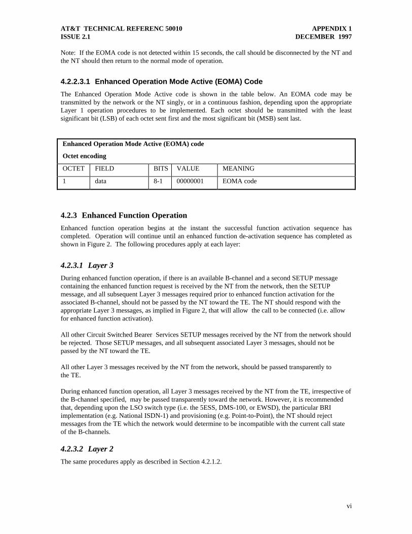
4.2.2.3.1 Enhanced Operation Mode Active (EOMA) Code
The Enhanced Operation Mode Active code is shown in the table below. An EOMA code may betransmitted by the network or the NT singly, or in a continuous fashion, depending upon the appropriateLayer 1 operation procedures to be implemented. Each octet should be transmitted with the leastsignificant bit (LSB) of each octet sent first and the most significant bit (MSB) sent last.
Enhanced Operation Mode Active (EOMA) code
Octet encoding
OCTET FIELD BITS VALUE MEANING
1 data 8-1 00000001 EOMA code
4.2.3 Enhanced Function Operation
Enhanced function operation begins at the instant the successful function activation sequence hascompleted. Operation will continue until an enhanced function de-activation sequence has completed asshown in Figure 2. The following procedures apply at each layer:
4.2.3.1 Layer 3
During enhanced function operation, if there is an available B-channel and a second SETUP messagecontaining the enhanced function request is received by the NT from the network, then the SETUPmessage, and all subsequent Layer 3 messages required prior to enhanced function activation for theassociated B-channel, should not be passed by the NT toward the TE. The NT should respond with theappropriate Layer 3 messages, as implied in Figure 2, that will allow the call to be connected (i.e. allowfor enhanced function activation).
All other Circuit Switched Bearer Services SETUP messages received by the NT from the network shouldbe rejected. Those SETUP messages, and all subsequent associated Layer 3 messages, should not bepassed by the NT toward the TE.
All other Layer 3 messages received by the NT from the network, should be passed transparently tothe TE.
During enhanced function operation, all Layer 3 messages received by the NT from the TE, irrespective ofthe B-channel specified, may be passed transparently toward the network. However, it is recommendedthat, depending upon the LSO switch type (i.e. the 5ESS, DMS-100, or EWSD), the particular BRIimplementation (e.g. National ISDN-1) and provisioning (e.g. Point-to-Point), the NT should rejectmessages from the TE which the network would determine to be incompatible with the current call stateof the B-channels.
4.2.3.2 Layer 2
The same procedures apply as described in Section 4.2.1.2.

AT&T TECHNICAL REFERENC 50010 APPENDIX 1ISSUE 2.1 DECEMBER 1997
vii
4.2.3.3 Layer 1
The operation at Layer 1 will vary based upon the enhanced operation function code associated with theenhanced function request. See the appropriate “Layer 1 Operation Procedures” in Section 6.
4.2.4 Enhanced Function De-Activation
An enhanced function will be de-activated when the call for the associated B-channel is disconnected fromthe network side as shown in Figure 2. At the point that the disconnect sequence concludes, the NTshould return to the normal mode of operation. The following procedures apply at each layer:
4.2.4.1 Layer 3
Enhanced function de-activation begins with the NT receiving a DISCONNECT message; the NT shouldrespond to a DISCONNECT with a RELEASE message8; finally de-activation concludes with the receiptof the RELEASE COMPLETE. The DISCONNECT and RELEASE COMPLETE messages should not bepassed by the NT toward the TE.
During enhanced function operation, all Layer 3 messages received by the NT from the TE may be passedtransparently toward the network. However, it is recommended that, depending upon the LSO switch type(i.e. the 5ESS, DMS-100, or EWSD), the particular BRI implementation (e.g. National ISDN-1) andprovisioning (e.g. Point-to-Point), the NT should reject messages from the TE which the network woulddetermine to be incompatible with the current call state of the B-channels.
During enhanced function operation, if there is an available B-channel and a second SETUP messagecontaining the enhanced function request is received by the NT from the network, then the SETUPmessage, and all subsequent Layer 3 messages required prior to enhanced function activation for theassociated B-channel, should not be passed by the NT toward the TE. The NT should respond with theappropriate Layer 3 messages, as implied in Figure 2, that will allow the call to be connected (i.e. allowfor enhanced function activation).
All other Circuit Switched Bearer Services SETUP messages received by the NT from the network shouldbe rejected. Those SETUP messages, and all subsequent associated Layer 3 messages, should not bepassed by the NT toward the TE.
All other Layer 3 messages received by the NT from the network, should be passed transparently tothe TE.
4.2.4.2 Layer 2
The same procedures apply as described in Section 4.2.1.2 until de-activation concludes.
4.2.4.3 Layer 1
Layer 1 will continue to operate according to enhanced function operation procedures (Section 6) untilfunction de-activation has concluded.
8 The Layer 3 message sequence and message encoding may be dependent upon switch type and the Layer 3 implementation.

AT&T TECHNICAL REFERENC 50010 APPENDIX 1ISSUE 2.1 DECEMBER 1997
viii
4.3 Transmission of Diagnostic Data
One of the capabilities associated with the enhanced operation functions of the NT is the transmission ofdiagnostic data toward the network on the associated B-channel. Data will be encoded as IRA9 andtransmitted in diagnostic data frames.
4.3.1 Diagnostic Data Frame
Diagnostic Data Frame
Octet encoding
OCTET FIELD BITS VALUE MEANING
n
(n < 255)
Diagnostic DataMessage
__ ASCII Diagnostic Data Message as defined in Sections7.1.5, 7.2.5, and 7.3.3
n + 1
Diagnostic DataMessage end-marker
8-1 00000010 End of the Diagnostic Data Message within thediagnostic data frame
n + 2
Checksum
(nibble C1)
8 -1 ASCII Hex Most significant nibble of 16 bit checksum
n + 3 (nibble C2) 8 - 1 ASCII Hex 2nd nibble of 16 bit checksum
n + 4 (nibble C3) 8 - 1 ASCII Hex 3rd nibble of 16 bit checksum
n + 5 (nibble C4) 8 - 1 ASCII Hex Least significant nibble of 16 bit checksum
4.3.1.1 Diagnostic Data Message Format
The Diagnostic Data Message contents of a Diagnostic data frame should consist of one to 255 octets ofIRA data. This includes all values from hexadecimal 00 to hexadecimal 7F with the exception ofhexadecimal 01 (EOMA code) and hexadecimal 02 (Diagnostic Data Message end-marker - see tableabove).
4.3.1.2 16 Bit Checksum
The checksum is computed in standard fashion by adding the octets of the Diagnostic Data Message.Each nibble of the checksum will be Hexadecimal encoded as IRA with the most significant nibble (C1)being transmitted first and the least significant nibble (C4) transmitted last.
4.3.1.3 Diagnostic Data Frame Encoding Example
As an example, if the Diagnostic Data Message contents are “Hello\n” (i.e. Hello followed by a new-linecharacter), the resulting Diagnostic Data Frame should be encoded as follows:
48 65 6c 6c 6f 0a 02 30 31 66 65
9 International Reference Alphabet (IRA) Information technology - 7-bit coded character set for information interchange, ITU
Recommendation T.50 (September 1992)

AT&T TECHNICAL REFERENC 50010 APPENDIX 1ISSUE 2.1 DECEMBER 1997
ix
4.3.2 End-of-Message Diagnostic Data Frame
After all Diagnostic Data Frames containing information have been transmitted, End-of-MessageDiagnostic Data Frames should be transmitted as described in Section 4.3.3. An End-of-MessageDiagnostic Data Frame should be encoded as shown in the table on the next page.
End-of-Message Diagnostic Data Frame
Octet encoding
OCTET FIELD BITS VALUE MEANING
1 Diagnostic DataMessage
8-1 00011010 Diagnostic Data Message used to indicate end-of-message.
2 Diagnostic DataMessage EndMarker
8-1 00000010 End of Diagnostic Data Message within theDiagnostic Data Frame.
3 Checksum
(nibble C1)
8 -1 00110000 ASCII Hex 30 ( IRA character “0” )
4 (nibble C2) 8 - 1 00110000 ASCII Hex 30 ( IRA character “0” )
5 (nibble C3) 8 - 1 00110001 ASCII Hex 31 ( IRA character “1” )
6 (nibble C4) 8 - 1 01000001 ASCII Hex 41 ( IRA character “A” )
4.3.3 Diagnostic Data Transmission Procedures
At the instant that enhanced function operation begins (i.e. the NT has detected at least 8 consecutiveoctets of EOMA code from the network on the B-channel), Diagnostic Data should be transmitted by theNT toward the network according to the Layer 1 operation procedures associated with the appropriateenhanced operations function code (Section 6). Data is transmitted as diagnostic data messages withinDiagnostic Data Frames encoded as described in Section 4.3.1.
The NT may divide Diagnostic Data to be transmitted to the network into any number of sequentialDiagnostic Data Frames. These frames should then be transmitted toward the network according to thefollowing procedures:
1. At least 16 octets of EOMA code (hexadecimal 01 - see Section 4.2.2.3.1) should be sent prior to thetransmission of the first Diagnostic Data Frame.
2. The NT should transmit a Diagnostic Data Frame by transmitting each octet with the least significantbit (LSB) of each octet sent first and the most significant bit (MSB) sent last.
3. Following each Diagnostic Data Frame sent, at least one octet of EOMA code should be transmitted.
4. Subsequent Diagnostic Data Frames do not require additional octets of EOMA code to proceed priorto their transmission; however, there must be at least one octet of EOMA code between eachDiagnostic Data Frame.
5. Following the transmission of the last Diagnostic Data Message Frame containing actual diagnosticinformation, the NT should transmit two End-of-Message Diagnostic Data Frames and theappropriate number of octets of EOMA code as described in steps 2 - 4 above.

AT&T TECHNICAL REFERENC 50010 APPENDIX 1ISSUE 2.1 DECEMBER 1997
x
4.3.3.1 Diagnostic Data Transmission Encoding Example
The following message “Hello\n Hello\n Hello\n” could be encoded as three Diagnostic Data Frames (witheach frame containing one “Hello\n”) as follows:
01 01 01 01 01 01 01 01 01 01 01 01 01 01 01 01 (Start of transmission - 16 octets of EOMA code)48 65 6c 6c 6f 0a 02 30 31 66 65 (Diagnostic Data Frame 1: Hello\n )01 (One octet of EOMA code )48 65 6c 6c 6f 0a 02 30 31 66 65 (Diagnostic Data Frame 2: Hello\n )01 01 (Two octets of EOMA code )48 65 6c 6c 6f 0a 02 30 31 66 65 (Diagnostic Data Frame 3: Hello\n )01 (One octet of EOMA code )1A 02 30 30 31 41 (End-of-Message Diagnostic Data Frame)01 (One octet of EOMA code )1A 02 30 30 31 41 (End-of-Message Diagnostic Data Frame )01 (One octet of EOMA code )
5. Enhanced Operations Functions
5.1 Operate B-Channel Loopback
This enhanced mode function directs the NT to loopback an individual B-Channel, specified in theenhanced function request, toward the network.10 The individual B-channel loopback may be eithertransparent or non-transparent11. It is non-inverting and should remain in-effect (i.e. not timed) until thisenhanced function is de-activated.
5.2 Transmit D-Channel Message Log Buffer
This enhanced operations function directs the NT to transmit the contents of its D-Channel Message LogBuffer toward the network in the B-channel associated with the enhanced function request.
The NT should save in the Message Log Buffer at least the last 25 Layer 3, and some Layer 2, D-channelmessages (Section 7.1.1), which are transmitted to or received from the network across the U-interface.The NT should provide an internal timing mechanism, initialized at power up, that will allow it to timestamp each message. In addition, the origination and destination end-points of the message along withthe direction the message was transmitted should also be recorded (i.e. network to NT, NT to network,network to TE, or TE to network).
5.3 Transmit M-Channel Performance Analysis Buffers
This enhanced operations function directs the NT to transmit the contents of its M-Channel PerformanceAnalysis Buffers toward the network in the B-channel associated with the enhanced function request.
Several performance parameters have been defined (Section 7.2.1) which will require the NT to observethe M-channel12 transmitted to and received from the network at the U-interface. The NT should providean internal timing mechanism, initialized at power up, that will allow it to keep track of the current timeand to make second-by-second observations of the M-channel. From these observations parameters should 10
It is intended, for ease of implementation, that the same U-interface chip sets designed to provide EOC functions can be used undermicroprocessor control to activate the loopback specified here.
11 “Transparent” is the ITU term used to indicate that the bits toward the loop are passed onward as well as looped back. A “non-transparent” loopback will not pass bits on-ward but will instead transmit “idle code.”
12 ANSI T1.601 -1992 clause 6 and clause 8 define the M-channel and its bit functions.

AT&T TECHNICAL REFERENC 50010 APPENDIX 1ISSUE 2.1 DECEMBER 1997
xi
be measured and then saved in the analysis buffers. Data should be saved in 15 minute bins for thecurrent 24 hour period and then accumulated in 24 hour bins in order to save approximately one weeksworth of data (Section 7.2.2).
5.4 Transmit Identification Message
This enhanced operations function directs the NT to transmit a message providing device type informationtoward the network in the B-channel associated with the enhanced function request.
The Identification Message will be used to retrieve information about the connected device which providesthe NT functionality. The information to be retained should include, but is not limited to: model,manufacturer, software revision level, and hardware revision level (Section 7.3.1).
6. Enhanced Operations Function CodesThis section specifies the valid enhanced operations function codes which should be recognized by theNT. The codes are transmitted within a Layer 3 SETUP message in either: (1) the “SubaddressInformation” fields of a “Called party subaddress” information element; or (2) the “Number digits” of a“Calling party number” information element. A SETUP message may contain enhanced operationfunction codes in one or both of the Called party subaddress and the Calling party number informationelements. If enhanced function codes are present in both information elements, they must correspond inorder for the function request to be considered valid by the NT; otherwise, the NT should remain in thenormal mode.
The encoding for the corresponding enhanced operations function code are shown below. In addition, theLayer 1 operation procedures which the NT should perform associated with these codes are described.
6.1 Operate B-Channel Loopback
6.1.1 Layer 1 Operation Procedures
Upon a successful enhanced function activation, the NT will operate the B-channel loopback (Section 5.1)for the associated B-channel.

AT&T TECHNICAL REFERENC 50010 APPENDIX 1ISSUE 2.1 DECEMBER 1997
xii
6.1.2 Called Party Subaddress Encoding
Operate B-Channel Loopback: Called Party Subaddress Information Element
Octet encoding
OCTET FIELD BITS VALUE MEANING
1 Information elementidentifier
8-1 01110001 Called party subaddress
2 Length of contents 8-1 00000111 Length of information element contents
3 Extension 8 1 Description is extended through next octets
Type of subaddress 7-5 010 User specified
Odd/even indicator 4 0 Not used
Spare 3-1 000
4 subaddress information 8-1 01000000 IRA character “@”
5 subaddress information 8-1 00000000 All zeros to indicates address of NT
6 subaddress information 8-1 01001100 IRA character “L”
7 subaddress information 8-1 01101111 IRA character “o”
8 subaddress information 8-1 01101111 IRA character “o”
9 subaddress information 8-1 01110000 IRA character “p”
6.1.3 Calling Party Number - Number Digits
The NT should recognize the following “Calling party number”, “Number digits” as the enhancedoperation function code for:
Operate B-Channel loopback: 790 555 570013
6.2 Transmit D-Channel Message Log Buffer/Operate B-ChannelLoopback
6.2.1 Layer 1 Operation Procedures
Upon a successful enhanced function activation, the NT should transmit the current contents of its D-Channel Messages Log Buffers toward the network on the associated B-channel (Section 5.2). TheMessage Log Buffer data should be encoded as described in Sections 4.3.1 and 7.1.5 and transmitted asdescribed in Section 4.3.3. Immediately following the transmission of the D-Channel Message Log Bufferdata, the NT should operate the B-channel loopback for that B-channel (Section 5.1).
13
If the network prepends any digits to the number digits specified (e.g. the country code prepended to the Calling party number on aninternational call) the NT should still recognize this number as a valid enhanced function code.

AT&T TECHNICAL REFERENC 50010 APPENDIX 1ISSUE 2.1 DECEMBER 1997
xiii
6.2.2 Called Party Subaddress Encoding
Transmit D-Channel Message Log Buffer/Operate B-Channel Loopback: Called party subaddressInformation Element
Octet encoding
OCTET FIELD BITS VALUE MEANING
1 Information elementidentifier
8-1 01110001 Called party subaddress
2 Length of contents 8-1 00001100 Length of information element contents
3 Extension 8 1 Description is extended through next octets
Type of subaddress 7-5 010 User specified
Odd/even indicator 4 0 Not used
Spare 3-1 000
4 subaddress information 8-1 01000000 IRA character “@”
5 subaddress information 8-1 00000000 All zeros to indicates address of NT
6 subaddress information 8-1 01001100 IRA character “L”
7 subaddress information 8-1 01101111 IRA character “o”
8 subaddress information 8-1 01101111 IRA character “o”
9 subaddress information 8-1 01110000 IRA character “p”
10 subaddress information 8-1 01000100 IRA character “D”
11 subaddress information 8-1 01100100 IRA character “d”
12 subaddress information 8-1 01100001 IRA character “a”
13 subaddress information 8-1 01110100 IRA character “t”
14 subaddress information 8-1 01100001 IRA character “a”
6.2.3 Calling Party Number - Number Digits
The NT should recognize the following “Calling party number”, “Number digits” as the enhancedoperation function code for:
Transmit D-Channel Message Log Buffer/Operate B-Channel loopback: 790 555 573014
6.3 Transmit M-Channel Performance Analysis Buffers/Operate B-ChannelLoopback
6.3.1 Layer 1 Operation Procedures
Upon a successful enhanced function activation, the NT should transmit the current contents of its M-channel performance analysis buffers toward the network on the associated B-channel (Section 5.3). Theanalysis buffer data should be encoded as described in Section 4.3.1 and 7.2.5 and transmitted asdescribed in Section 4.3.3. Immediately following the transmission of the M-Channel PerformanceAnalysis Buffers data, the NT should operate the B-channel loopback for that B-Channel (Section 6.1).
14 If the network prepends any digits to the number digits specified (e.g. the country code prepended to the Calling party number on an
international call) the NT should still recognize this number as a valid enhanced function code.

AT&T TECHNICAL REFERENC 50010 APPENDIX 1ISSUE 2.1 DECEMBER 1997
xiv
6.3.2 Called Party Subaddress Encoding
Transmit M-Channel Performance Analysis Buffers/Operate B-Channel Loopback: Called partysubaddress Information Element
Octet encoding
OCTET FIELD BITS VALUE MEANING
1 Information elementidentifier
8-1 01110001 Called party subaddress
2 Length of contents 8-1 00001100 Length of information element contents
3 Extension 8 1 Description is extended through next octets
Type of subaddress 7-5 010 User specified
Odd/even indicator 4 0 Not used
Spare 3-1 000
4 subaddress information 8-1 01000000 IRA character “@”
5 subaddress information 8-1 00000000 All zeros to indicates address of NT
6 subaddress information 8-1 01001100 IRA character “L”
7 subaddress information 8-1 01101111 IRA character “o”
8 subaddress information 8-1 01101111 IRA character “o”
9 subaddress information 8-1 01110000 IRA character “p”
10 subaddress information 8-1 01001101 IRA character “M”
11 subaddress information 8-1 01100100 IRA character “d”
12 subaddress information 8-1 01100001 IRA character “a”
13 subaddress information 8-1 01110100 IRA character “t”
14 subaddress information 8-1 01100001 IRA character “a”
6.3.3 Calling Party Number - Number Digits
The NT should recognize the following “Calling party number”, “Number digits” as the enhancedoperation function code for:
Transmit M-Channel Performance Analysis Buffers/Operate B-Channel Loopback: 790 555 576015
6.4 Transmit Identification Message/Operate B-channel Loopback
6.4.1 Layer 1 Operation Procedures
Upon a successful enhanced function activation, the NT should first transmit its Identification Message(Section 5.4) toward the network on the associated B-channel. This diagnostic data should be encoded asdescribed in Sections 4.3.1 and 7.3.3 and then transmitted as described in Section 4.3.3. Immediatelyfollowing the transmission of the Identification Message data, the NT should operate the B-Channelloopback for that B-Channel (Section 5.1).
15 If the network prepends any digits to the number digits specified (e.g. the country code prepended to the Calling party number on an
international call) the NT should still recognize this number as a valid enhanced function code.

AT&T TECHNICAL REFERENC 50010 APPENDIX 1ISSUE 2.1 DECEMBER 1997
xv
6.4.2 Called Party Subaddress Encoding
Transmit Identification Message/Operate B-Channel Loopback: Called party subaddressInformation Element
Octet encoding
OCTET FIELD BITS VALUE MEANING
1 Information elementidentifier
8-1 01110001 Called party subaddress
2 Length of contents 8-1 00001011 Length of information element contents
3 Extension 8 1 Description is extended through next octets
Type of subaddress 7-5 010 User specified
Odd/even indicator 4 0 Not used
Spare 3-1 000
4 subaddress information 8-1 01000000 IRA character “@”
5 subaddress information 8-1 00000000 All zeros to indicates address of NT
6 subaddress information 8-1 01001100 IRA character “L”
7 subaddress information 8-1 01101111 IRA character “o”
8 subaddress information 8-1 01101111 IRA character “o”
9 subaddress information 8-1 01110000 IRA character “p”
10 subaddress information 8-1 01001110 IRA character “N”
11 subaddress information 8-1 01010100 IRA character “T”
12 subaddress information 8-1 01001001 IRA character “I”
13 subaddress information 8-1 01000100 IRA character “D”
6.4.3 Calling Party Number - Number Digits
The NT should recognize the following “Calling party number”, “Number digits” as the enhancedoperation function code for:
Transmit Identification Message/Operate B-Channel Loopback: 790 555 684316
6.5 Transmit all Diagnostic Data/Operate B-Channel Loopback
6.5.1 Layer 1 Operation Procedures
Upon a successful enhanced function activation, the NT should first transmit the current contents of its D-Channel Message Log Buffer (Section 5.2), then its M-Channel Performance Analysis Buffers (Section5.3), and finally its Identification Message (Section 5.4) toward the network on the associated B-channel.The Analysis Buffer data should be encoded as described in Sections 4.3.1, 7.1.5, 7.2.5 and 7.3.3 and thentransmitted as described in Section 4.3.3. Immediately following the transmission of this data, the NTshould operate the B-channel loopback for that B-channel (Section 5.1).
16 If the network prepends any digits to the number digits specified (e.g. the country code prepended to the Calling party number on an
international call) the NT should still recognize this number as a valid enhanced function code.

AT&T TECHNICAL REFERENC 50010 APPENDIX 1ISSUE 2.1 DECEMBER 1997
xvi
6.5.2 Called Party Subaddress Encoding
Transmit All Diagnostic Data/Operate B-Channel Loopback: Called party subaddress InformationElement
Octet encoding
OCTET FIELD BITS VALUE MEANING
1 Information elementidentifier
8-1 01110001 Called party subaddress
2 Length of contents 8-1 00001110 Length of information element contents
3 Extension 8 1 Description is extended through next octets
Type of subaddress 7-5 010 User specified
Odd/even indicator 4 0 Not used
Spare 3-1 000
4 subaddress information 8-1 01000000 IRA character “@”
5 subaddress information 8-1 00000000 All zeros to indicates address of NT
6 subaddress information 8-1 01001100 IRA character “L”
7 subaddress information 8-1 01101111 IRA character “o”
8 subaddress information 8-1 01101111 IRA character “o”
9 subaddress information 8-1 01110000 IRA character “p”
10 subaddress information 8-1 01000001 IRA character “A”
11 subaddress information 8-1 01101100 IRA character “l”
12 subaddress information 8-1 01101100 IRA character “l”
13 subaddress information 8-1 01100100 IRA character “d”
14 subaddress information 8-1 01100001 IRA character “a”
15 subaddress information 8-1 01110100 IRA character “t”
16 subaddress information 8-1 01100001 IRA character “a”
6.5.3 Calling Party Number - Number Digits
The NT should recognize the following “Calling party number”, “Number digits” as the enhancedoperation function code for:
Transmit All Diagnostic Data/Operate B-Channel Loopback”: 790 555 536417
17 If the network prepends any digits to the number digits specified (e.g. the country code prepended to the Calling party number on an
international call) the NT should still recognize this number as a valid enhanced function code.

AT&T TECHNICAL REFERENC 50010 APPENDIX 1ISSUE 2.1 DECEMBER 1997
xvii
7. Diagnostic Data
7.1 D-Channel Message Log Buffer
7.1.1 Messages To Be Saved
The NT should be able to recognize, and store in its analysis buffers, all Layer 3 messages defined in theSection 3, “Reference CO Switch Specifications” in the main body of this Technical Reference18.
The following Layer 2 unnumbered U-frames commands should also be stored:
Set asynchronous balanced mode enabled (SABME)
Unnumbered information (UI): Include the following message types only:
Identity request (User To Network)
Identity assigned (Network To User)
Identity denied (Network To User)
Disconnect (DISC)
The following Layer 2 U-frame responses should be stored:
Disconnected mode (DM)
Unnumbered acknowledgment (UA)
Frame reject (FRMR)
7.1.2 Local Timing
The NT will be required to provide a local timing mechanism for time stamping D-channel messages to besaved as well as for determining the current time. The initial time, T0, should be coincident with the pointat which the NT is powered on unless battery backup is available.19
If the NT is allowed to run indefinitely it should be able to time stamp data for up to 999 days before thebuffer resets. The NT should be able to provide 0.1 second (100 millisecond) accuracy when timestamping data, although 0.001 second accuracy (1 millisecond) accuracy is preferred.
7.1.3 Local Storage
The time and D-channel messages recorded by the NT should be saved locally as described below.
Current Time: The NT should save the current time, measured in seconds from time T0 (see “LocalTiming” Section 7.1.2).
Message Time Stamp: For each D-channel message recorded by the NT, it should associate a timestamp, measured in seconds from time T0 (see “Local Timing” Section 7.1.2).
18
While most Layer 3 messages will be contained within Layer 2 Information frames (I- frames), there may be instances where themessages are contained in Layer 2 Unnumbered frames (U-frames). Layer 3 information contained in either I-frames or U-framesshould be logged.
19 Battery backup of the D-Channel Message Log buffer is not required although it is strongly recommended. If battery backup isprovided, initialization should only occur once unless the NT is reset through manual intervention (e.g. by disrupting the powerbackup) or local timing is disrupted.

AT&T TECHNICAL REFERENC 50010 APPENDIX 1ISSUE 2.1 DECEMBER 1997
xviii
Message End Points and Direction: For each D-channel message recorded by the NT, it shouldassociate the transmit and receive end points as well as the direction the message traveled. The fourmessage direction possibilities are:
Network to TE: Indicates that the message was transmitted from the network to the terminalequipment.
TE to Network: Indicates that the message was transmitted from the terminal equipment to thenetwork.
Network to NT: Indicates that the NT intercepted the message transmitted by the network.
NT to Network: Indicates that the NT transmitted the message to the network.
Message Content: Any Layer 3 or Layer 2 messages to be saved (Section 7.1.1) should be recorded inbinary exactly as they are observed at the U-interface. The storage requirements will vary based uponmessage type.
7.1.4 Buffer Initialization
The D-Channel Messages Analysis Buffers should be initialized (contents cleared) after NT power up andat the point that “transparency of the transmission” is provided on the network side of the NT(transparency is defined in ANSI T1.601-1992 clause 6.4.6.6). Buffer initialization will occur at sometime after T0 as defined in the Local Timing section above (Section 7.1.2).
7.1.5 Return of Diagnostic Data
During enhanced function operation, the time stamped D-channel messages, along with the currenttime20, should be transmitted from the NT toward the network.
7.1.5.1 Modification of Number Digits
To ensure customer privacy, it is critical that the “Number digits” field of any “Called party address” or“Calling party address” information elements contained within saved Layer 3 messages are not returnedin a diagnostic data message in their original format. Instead, each number digit should be replaced witha zero (0), encoded in the same format as the original number digits. As an example, if the saved originalcalled party address number digits were “800 555 1212” then the number digits to be returned within thediagnostic data message would be “000 000 0000.”
7.1.5.2 Diagnostic Data Message Encoding
The D-Channel Message Log Buffer data will be formatted into a report that consists of IRA lines of text.This report can then be divided into sequential Diagnostic Data Messages to be included in DiagnosticData Frames and transmitted toward the network by the NT as specified in Section 4.3.
20 In order that the current time that it is received by the network from the NT is as close to the current “real time” as possible, the value of
the current time should not be encoded until the last possible moment prior to actual transmission of the diagnostic data frame.

AT&T TECHNICAL REFERENC 50010 APPENDIX 1ISSUE 2.1 DECEMBER 1997
xix
7.1.5.2.1 Report Format
The D-Channel Message Log Report should be formatted as follows:
Report HeaderD-channel message 1: End Point and Direction & Time StampD-channel message 1: Contents |D-channel message N: End Point and Direction & Time StampD-channel message N: ContentsReport Trailer
7.1.5.2.2 Report Header and Trailer Format
Report Header: This is the first line of the report and will be formatted as the text “RPT” followed by anIRA space character (‘ ‘) and the current time formatted as specified in Section 7.1.5.2.3. The headerwill end with an IRA new-line character.
Report Trailer: This is the last line of the report and will be formatted as the text “END” followed by anIRA space character (‘ ‘) and the current time formatted as specified in Section 7.1.5.2.3. The trailer willend with an IRA new-line character.
7.1.5.2.3 Message End Points and Direction & Time Stamp Format
For each D-channel message to be reported a line will proceed it which contains the message end pointand direction followed by the message time stamp. An IRA space character (‘ ‘) should separate the twofields and the time stamp should be followed by an IRA new-line character.
Message end point and Direction: The format for reporting the message end point and direction is asfollows:
Network to TE: NET->TETE to Network: NET<-TENetwork to NT: NET->NTNT to Network: NET<-NT
Time stamps: The format for reporting the time is as follows:DDD HH:MM:SS.mmmWhere:
DDD: the day (000 to 999)HH: the hour (00 - 23)MM: the minute (00 - 59)SS: the second (00 - 59)mmm: the millisecond (000-999)
Note: (1) the DDD field is followed by an IRA space character (’ ‘); (2) the HH, MM and SS fields areseparated by an IRA colon character (‘:’); and (3) the SS and mmm fields are separated by an IRA periodcharacter (‘.‘).
7.1.5.2.4 Message Content Format
The format for reporting the contents of Layer 2 and Layer 3 messages should be Hexadecimal encoded asIRA. Each message is followed by an IRA new-line character.
AT&T TECHNICAL REFERENC 50010 APPENDIX 1ISSUE 2.1 DECEMBER 1997
xx
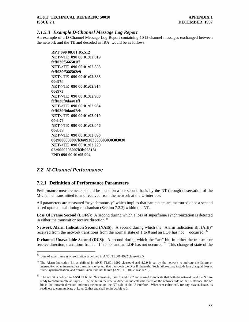
7.1.5.3 Example D-Channel Message Log ReportAn example of a D-Channel Message Log Report containing 10 D-channel messages exchanged betweenthe network and the TE and decoded as IRA would be as follows:
RPT 090 00:01:05.512NET<-TE 090 00:01:02.819fcff030f566501ffNET->TE 090 00:01:02.853feff030f566502e9NET<-TE 090 00:01:02.88800e97fNET->TE 090 00:01:02.91400e973NET<-TE 090 00:01:02.950fcff030f0daa01ffNET->TE 090 00:01:02.984feff030f0daa02ebNET<-TE 090 00:01:03.01900eb7fNET->TE 090 00:01:03.04600eb73NET<-TE 090 00:01:03.09600e9000008007b3a09303030303030303030NET->TE 090 00:01:03.22902e9000208007b3b028181END 090 00:01:05.994
7.2 M-Channel Performance
7.2.1 Definition of Performance Parameters
Performance measurements should be made on a per second basis by the NT through observation of theM-channel transmitted to and received from the network at the U-interface.
All parameters are measured “asynchronously” which implies that parameters are measured once a secondbased upon a local timing mechanism (Section 7.2.2) within the NT.
Loss Of Frame Second (LOFS): A second during which a loss of superframe synchronization is detectedin either the transmit or receive direction.21
Network Alarm Indication Second (NAIS): A second during which the “Alarm Indication Bit (AIB)”received from the network transitions from the normal state of 1 to 0 and an LOF has not occurred. 22
D-channel Unavailable Second (DUS): A second during which the “act” bit, in either the transmit orreceive direction, transitions from a “1” to “0” and an LOF has not occurred.23 This change of state of the
21 Loss of superframe synchronization is defined in ANSI T1.601-1992 clause 6.2.5.
22 The Alarm Indication Bit as defined in ANSI T1.601-1992 clauses 6 and 8.2.9 is set by the network to indicate the failure orinterruption of an intermediate transmission system that transports the D or B channels. Such failures may include loss of signal, loss offrame synchronization, and transmission terminal failure (ANSI T1.601- clause 8.2.9).
23 The act bit is defined in ANSI T1.601-1992 clauses 6, 6.4.6.6, and 8.2.2 and is used to indicate that both the network and the NT areready to communicate at Layer 2. The act bit in the receive direction indicates the status on the network side of the U-interface, the actbit in the transmit direction indicates the status on the NT side of the U-interface. Whenever either end, for any reason, losses itsreadiness to communicate at Layer 2, that end shall set its act bit to 0.

AT&T TECHNICAL REFERENC 50010 APPENDIX 1ISSUE 2.1 DECEMBER 1997
xxi
act bit must occur in at least three consecutive superframes (Note: If the observation of the threeconsecutive occurrences crosses a measurement second boundary, then a DUS should be recorded for eachof those seconds).
Near End Block Error Second (NEBES): A second during which one or more superframe “CyclicRedundancy Check (CRC)” errors are detected in the receive direction and an LOF has not occurred.24
Far End Block Error Second (FEBES): A second during which the “FEBE” bit in the receive directiontransitions from a ”1” to a “0” and an LOF has not occurred.25
7.2.2 Local Timing
The NT will be required to provide a local timing mechanism for performance parameter measurementand for determining the current time. The initial time, T0, should be set to be coincident with the point atwhich the NT is powered on unless battery backup is available. 26
If the NT is allowed to run indefinitely it should be able to time stamp data for up to 999 days before thebuffer resets. The NT should be able to provide 0.1 second (100 millisecond) accuracy when timestamping data, although 0.001 second accuracy (1 millisecond) accuracy is preferred.
7.2.3 Local Storage
The time and performance parameter measurements recorded by the NT should be saved locally asdescribed below.
Current Time: The NT should save the current time, measured in seconds from time T0 (Section 7.2.2).
96 Fifteen Minute Bins: For storage of the last 24 hours worth of data. Measurements begin at time T0
and after each 15 minute period the contents of bin i should be moved to bin i+1 with data from bin 96being discarded.
15 Minute Parameter Values: Since parameter values will range from 0 to 900, each parametermay be saved as a 10 bit unsigned integer.
Seven 24 Hour Bins: Data in these bins should be accumulated according to the following procedure: A24-hour clock should be kept beginning with time T0. At each 24 hour point, the measurements for eachparameter contained in the 96 fifteen minute bins should be added together to derive a 24 hour total.These values are stored in the first 24 hour bin. Prior to over-writing the contents of the first bin, itscontents should be moved to the second bin. The contents of bin i should be moved to bin i+1 with datafrom bin 7 being discarded.
24 Hour Parameter Values: Since parameter values will range from 0 to 86400, eachparameter may be saved as a 17 bit unsigned integer.
7.2.4 Buffer Initialization
All M-channel Performance Analysis Buffers should be initialized (set to zero) after NT power up27 and atthe point that “transparency of the transmission” is provided on the network side of the NT.28 The status
24 Near End Block Error Second (NEBES) is defined in ANSI T1.601-1992 clause 6 and 8.1.
25 Far End Block Error Second (FEBS) is defined in ANSI T1.601-1992 clause 6 and 8.2.1.
26 Battery backup of the D-Channel Message Log buffer is not required although it is strongly recommended. If battery backup isprovided, initialization should only occur once unless the NT is reset through manual intervention (e.g. by disrupting the powerbackup) or local timing is disrupted.

AT&T TECHNICAL REFERENC 50010 APPENDIX 1ISSUE 2.1 DECEMBER 1997
xxii
of the user side of the NT should be ignored. Buffer initialization will occur at some time after T0 asdefined in the “Local Timing” section above (Section 7.2.2).
7.2.5 Return of Diagnostic Data
During enhanced function operation, the M-Channel Performance Analysis Buffers data, along with thecurrent time29, should be transmitted from the NT toward the network.
7.2.5.1 Diagnostic Data Message Encoding
The M-Channel Performance Analysis Buffer data will be formatted into a report that consists of IRAlines of text. This report can then be divided into sequential diagnostic data messages to be included inDiagnostic Data Frames and transmitted toward the network by the NT as specified in Section 4.3.
7.2.5.1.1 Report Format
The M-channel performance data report should be formatted as follows:
LOFS 15 minute and 24 hour parameter data sectionNEBES 15 minute and 24 hour parameter data sectionFEBES 15 minute and 24 hour parameter data sectionDUS 15 minute and 24 hour parameter data sectionNAIS 15 minute and 24 hour parameter data sectionReport Trailer
7.2.5.1.2 15 Minute and 24 Hour Parameter Data Sections Format
For each of the parameters, the data will be formatted as follows:
Section Header: This is the first line of each section and consists of the name of the parameter followedby an IRA space character and the current time encoded as described in section 7.2.5.1.4 below.
15 Minute Data: The section header is followed by the text “15m:” indicating the 15 minute bins, andthe 96 corresponding values, with each value encoded as three IRA digits with 16 values per line andconsecutive values separated by an IRA space character (‘ ‘). The current value will be transmitted firstand the least recent value will be transmitted last.
24 Hour Data: The 15 minute data values are followed by a line consisting of the text “day:” indicatingthe daily bins, and the seven corresponding values, with each value encoded as six IRA digits andconsecutive values separated by and IRA space character (‘ ‘). The most recent value will be transmittedfirst and the least recent value will be transmitted last.
27 Battery backup of the M-Channel Performance buffer is not required although it is strongly recommended. If battery backup is
provided, initialization should only occur once unless the NT is reset through manual intervention (e.g. by disrupting the powerbackup) or local timing is disrupted.
28 Transparency is defined in ANSI T1.601-1992 clause 6.4.6.6.
29 In order that the current time that it is received by the network from the NT is as close to the current “real time” as possible, the value ofthe current time should not be encoded until the last possible moment prior to actual transmission of the diagnostic data frame.
AT&T TECHNICAL REFERENC 50010 APPENDIX 1ISSUE 2.1 DECEMBER 1997
xxiii
7.2.5.1.3 Report Trailer Format
The report trailer is the last line of the report and will be formatted as the text “END” followed by an IRAspace character (‘ ‘) and the current time formatted as specified in Section 7.2.5.1.4. The trailer will endwith an IRA new-line character.
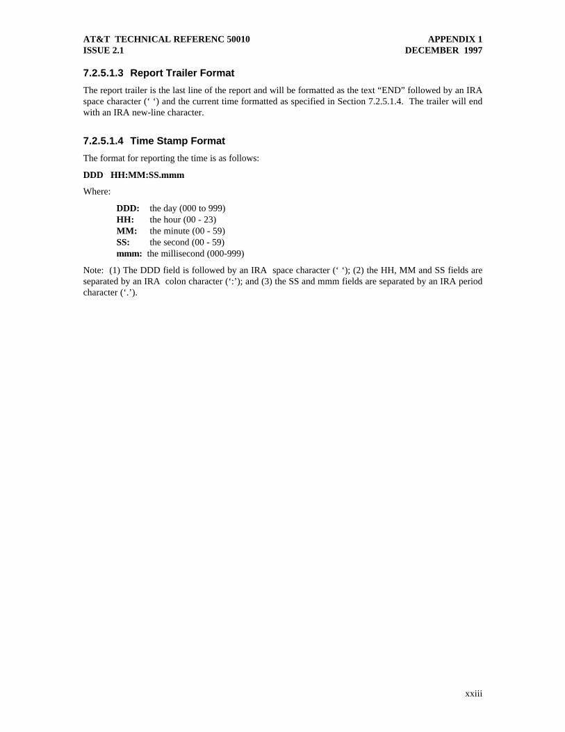
7.2.5.1.4 Time Stamp Format
The format for reporting the time is as follows:
DDD HH:MM:SS.mmm
Where:
DDD: the day (000 to 999)HH: the hour (00 - 23)MM: the minute (00 - 59)SS: the second (00 - 59)mmm: the millisecond (000-999)
Note: (1) The DDD field is followed by an IRA space character (‘ ‘); (2) the HH, MM and SS fields areseparated by an IRA colon character (‘:’); and (3) the SS and mmm fields are separated by an IRA periodcharacter (‘.’).

AT&T TECHNICAL REFERENC 50010 APPENDIX 1ISSUE 2.1 DECEMBER 1997
xxiv
7.2.5.2 Example M-channel performance data reportAn example of an M-channel performance data report decoded as IRA would be as follows:
LOFS 010 00:21:57.11615m: 000 03D 000 000 000 000 000 000 000 000 000 000 000 000 000 000 000 000 000 000 000 000 000 000 000 000 000 000 000 000 000 000 000 000 000 000 000 000 000 000 000 000 000 000 000 000 000 000 000 000 000 000 000 000 000 000 000 000 000 000 000 000 000 000 000 000 000 000 000 000 000 000 000 000 000 000 000 000 000 000 000 000 000 000 000 000 000 000 000 000 000 000 000 000 000 000day: 000000 000000 000000 000000 000000 000000 000000NEBES 010 00:21:57.71315m: 000 001 000 000 000 000 000 000 000 000 000 000 000 000 000 000 000 000 000 000 000 000 000 000 000 000 000 000 000 000 000 000 000 000 000 000 000 000 000 000 000 000 000 000 000 000 000 000 000 000 000 000 000 000 000 000 000 000 000 000 000 000 000 000 000 000 000 000 000 000 000 000 000 000 000 000 000 000 000 000 000 000 000 000 000 000 000 000 000 000 000 000 000 000 000 000day: 000000 000000 000000 000000 000000 000000 000000FEBES 010 00:21:58.31115m: 000 004 000 000 000 000 000 000 000 000 000 000 000 000 000 000 000 000 000 000 000 000 000 000 000 000 000 000 000 000 000 000 000 000 000 000 000 000 000 000 000 000 000 000 000 000 000 000 000 000 000 000 000 000 000 000 000 000 000 000 000 000 000 000 000 000 000 000 000 000 000 000 000 000 000 000 000 000 000 000 000 000 000 000 000 000 000 000 000 000 000 000 000 000 000 000day: 000000 000000 000000 000000 000000 000000 000000DUS 010 00:21:58.90915m: 000 000 000 000 000 000 000 000 000 000 000 000 000 000 000 000 000 000 000 000 000 000 000 000 000 000 000 000 000 000 000 000 000 000 000 000 000 000 000 000 000 000 000 000 000 000 000 000 000 000 000 000 000 000 000 000 000 000 000 000 000 000 000 000 000 000 000 000 000 000 000 000 000 000 000 000 000 000 000 000 000 000 000 000 000 000 000 000 000 000 000 000 000 000 000 000day: 000000 000000 000000 000000 000000 000000 000000NAIS 010 00:21:59.50415m: 000 000 000 000 000 000 000 000 000 000 000 000 000 000 000 000 000 000 000 000 000 000 000 000 000 000 000 000 000 000 000 000 000 000 000 000 000 000 000 000 000 000 000 000 000 000 000 000 000 000 000 000 000 000 000 000 000 000 000 000 000 000 000 000 000 000 000 000 000 000 000 000 000 000 000 000 000 000 000 000 000 000 000 000 000 000 000 000 000 000 000 000 000 000 000 000day: 000000 000000 000000 000000 000000 000000 000000END 010 00:22:00.102

AT&T TECHNICAL REFERENC 50010 APPENDIX 1ISSUE 2.1 DECEMBER 1997
xxv
7.3 Identification Message
7.3.1 Definition of Identification Message Parameters
7.3.1.1 Mandatory ParametersWhen transmitting the Identification Message, the following parameters must be included (even if theircontents are null):
Model: The Model name for the NT device.
Manufacturer: The manufacturer of the NT device.
Software-Revision-Level: The revision level for the software resident in the NT device. The format ofthe revision level should be IRA , but is otherwise defined by the manufacturer of the NT device.
Hardware-Revision-Level: The revision level for the NT device hardware. The format of the revisionlevel should be IRA , but is otherwise defined by the manufacturer of the NT device.
7.3.1.2 Optional ParametersThe NT device can include vendor-specific parameters other than those defined above. It is recommendedthat any parameter definitions should include some vendor-specific text in the parameter name in order toalleviate any conflict with parameter definitions that may be defined by future revisions of thisspecification.
The optional parameters portion of the Identification Message offers the vendor an opportunity to providemore detailed device-specific information, e.g. the serial number (see the example in Section 7.3.2.2). Italso provides a mechanism for transmitting additional diagnostic information. For example: (1) a report offar-end disconnects due to a PAP/CHAP authentication failure and (2) a report of TCP (TransmissionControl Protocol) connection failures.
7.3.2 Return of Diagnostic Data
During enhanced function operation, the Identification Message parameters, along with the current time30,should be transmitted from the NT toward the network.
7.3.2.1 Diagnostic Data Message Encoding
The Identification Message data will be formatted into a report that consists of IRA lines of text. Thisreport can then be divided into sequential diagnostic data messages to be included in diagnostic dataframes and transmitted toward the network by the NT as specified in Section 4.3.
7.3.2.1.1 Report Format
The Identification Message should be formatted as follows:
Report HeaderMandatory and Optional Parameter Data SectionReport Trailer
30 In order that the current time that it is received by the network from the NT is as close to the current “real time” as possible, the value of
the current time should not be encoded until the last possible moment prior to actual transmission of the diagnostic data frame.

AT&T TECHNICAL REFERENC 50010 APPENDIX 1ISSUE 2.1 DECEMBER 1997
xxvi
7.3.2.1.2 Report Header and Trailer Format
Report Header: This is the first line of the report and will be formatted as the text “NTID” followed byan IRA space character (‘ ‘) and the current time formatted as specified in Section 7.3.3.1.4 below. Theheader will end with an IRA new-line character.
Report Trailer: This is the last line of the report and will be formatted as the text “END” followed by anIRA space character (‘ ‘) and the current time formatted as specified in Section 7.3.3.1.4. The trailer willend with an IRA new-line character.
7.3.2.1.3 Mandatory and Optional Parameter Data Section Format
For each of the parameters, the data will be formatted as follows:
The Identification Message parameter name, an IRA colon character (‘:’), an IRA space character (‘ ‘),the value for the parameter, and an IRA new-line character. The order in which parameters aretransmitted is not significant, although it is recommended that the mandatory identification messageparameters be transmitted first.
7.3.2.1.4 Time Stamp Format
The format for reporting the time is as follows:
DDD HH:MM:SS.mmm
Where:
DDD: the day (000 to 999)HH: the hour (00 - 23)MM: the minute (00 - 59)SS: the second (00 - 59)mmm: the millisecond (000-999)
Note: (1) The DDD field is followed by an IRA space character (‘ ‘); (2) the HH, MM and SS fields areseparated by an IRA colon character (‘:’); and (3) the SS and mmm fields are separated by an IRA periodcharacter (‘.’).
7.3.2.2 Example Identification Message ReportAn example of an Identification Message report decoded as IRA would be as follows:
NTID 010 00:21:57.116Model: ACME-222Manufacturer: ACME Telecom, Inc.Software-Revision-Level: 2.03Hardware-Revision-Level: RevBACME-Mode-Setting: mode-7Serial #: A121897PAP/CHAP Failure: Far-End Disconnect at 009 00:09.23.03.239END 010 00:21:57.250

AT&T TECHNICAL REFERENC 50010 APPENDIX 1ISSUE 2.1 DECEMBER 1997
xxvii
8. REFERENCES
1. Integrated Services Digital Network (ISDN) - Basic Access Interface for Use on Metallic Loopsfor Application on the Network Side of the NT (Layer 1 Specification) ANSI T1.601 - 1992.
2. Recommendation T.50, International Reference Alphabet (IRA) (Formerly International
Alphabet No. 5 or IA5), Information Technology - 7-Bit Coded Character Set for InformationInterchange, CCITT Document, September 1992.