technical report 1 generic convex collision detection ...technical report 1 generic convex collision...
TRANSCRIPT
TECHNICAL REPORT 1
Generic Convex Collision Detectionusing Support Mapping
Benjamin Kenwright
Abstract—A collision detection algorithm that is computationally efficient, numerically stable, and straightforward to implement is avaluable tool in any virtual environment. This includes the ability to determine accurate proximity information, such as, penetrationdepth, contact position, and separating normal. We explore the practical and scalable issues of support mapping for use in detectingcontact information for convex shapes. While support mapping is a popular technique used in common algorithms, such as, GJK, EPA,and XenonCollide, we demonstrate how to implement an uncomplicated algorithm and identify pitfalls in three-dimensional space. Weexplore the scalable nature of the technique for use in massively parallel execution environments and emphasise trade-offs in terms ofperformance and accuracy to achieve consistent real-time frame-rates through optimisations.
Index Terms—collision detection, Minkowski, support point, contact information, real-time, iterative, features
F
1 INTRODUCTION
A COMPUTATIONALLY efficient, straightforward and ro-bust generic collision detection algorithm is essential
in virtual environments. Collision detection is a diversearea (e.g., broad, narrow, convex, concave, discrete, andcontinuous). Typically, narrow phase is the most specificand most expensive collision process, since the intersectiontests need to be exact while computing detailed contactdata. We focus on convex rigid body bodies in discretesystems, particularly the support mapping concept and itsapplication in real-time interactive solutions. The algorithmnot only needs to correctly detect collisions but also generateaccurate contact information, such as, penetration depthwhile handling numerical errors.
Due to the immense importance of collision detection al-gorithms, numerous research has been devoted to the prob-lem in recent decades. This has produced numerous excitingand novel solutions, such as, GJK [1], V-Clip [10], Lin-Canny[9], and I-COLLIDE [3]. Each of these techniques have nu-merous advantages and disadvantages that evolve aroundthe understanding of fundamental geometric principles. Thealgorithms can be implemented in three-dimensional spaceusing vector algebra to derive information, such as, facenormals, separating planes, support points, and distances.However, implementing an algorithm effectively withoutincorporating engineering solutions for special cases that isscalable and easy to understand can be challenging and timeconsuming.
We explain the concept of support mapping and itsapplication in popular collision detection algorithms forgenerating accurate narrow phase contact information. Wepresent experimental results to demonstrate scalability,practical pitfalls, memory, performance, and hybrid adap-tations. We provide a simplified real-world implementationto illustrate the elegant compact nature of the algorithm.
2 RELATED WORK
We show where support mapping sits in terms of other tech-niques for solving contact and collision problems (Figure
1). Explaining all the collision detection algorithms wouldbe beyond the scope of this article, instead we show keyalgorithms that have been successful and relate to supportmapping approach presented in this article.
A number of algorithms build upon the general supportmapping and Minkowski Difference concept as we usein this article, such as, Gilbert-Johnson-Keerthi (GKJ) [5],XenoCollide [14], and Expanding Polytope Algorithm (EPA)[15]. However, we focus on the algorithms ability to solvepractical problems through hybrid adaptations (i.e., look-uptables) and through exploitation of technological advance-ments, such as, the graphical processing unit (GPU). Cube-mapping has been used to speed-up the look-up method[12].
Support mapping is a popular technique that is sup-ported in numerous, open source and commercial physicsengines, such as, Bullet (GJK) Physics Engine [4], OpenDynamics Engine (ODE) [13], Havoc (GHK variant of GJK).For a comprehensive evaluation and comparison of physicsengines and their differences, see Boeing and Braunl [2],similarly, Kockara et al. [8] provides an overview of thedifferent collision detection algorithms and differences.
3 OVERVIEW
We demonstrate key concepts that are not always madeexplicit with the algorithm and are crucial in practical highperformance narrow phase implementations.
X closest points between pairs of convex polytopes (prox-imity data)
X contact information (e.g., normal, penetration, contactpoint), which includes handling deep penetrations
X degenerate convex shape with holes and concave sub-elements (i.e., shape vertices and ‘not’ the topology andgeometric face information)
X efficient and can scale well to high poly meshesX take advantage of coherency between frame updatesX implemented easily without much difficulty
TECHNICAL REPORT 2
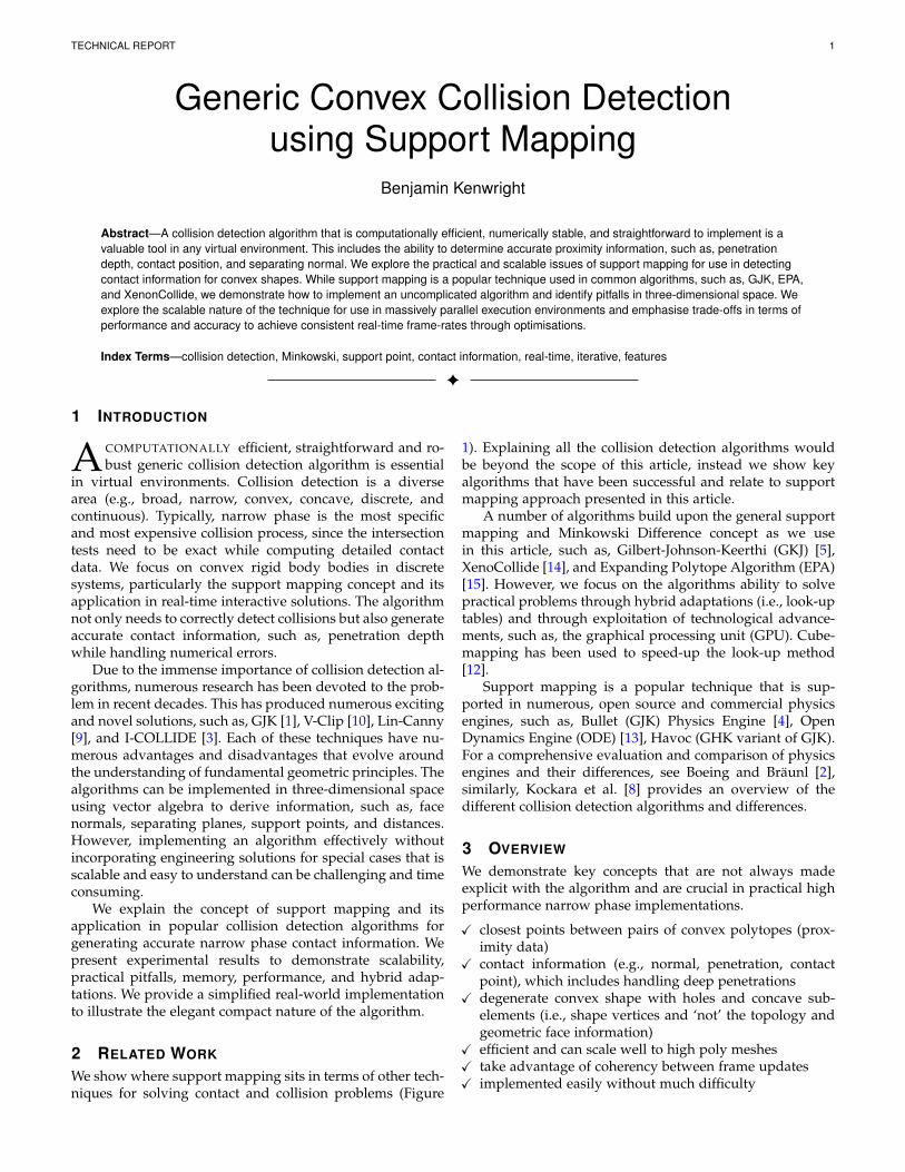
Fig. 1. Timeline Overview - Visual illustration of collision detection methods related to support mapping concepts. [A] [11], [B] [5], [C] [9], [D] [10],[E] [1], [F] [7], [G] [14], [H] [3], [I] [6].
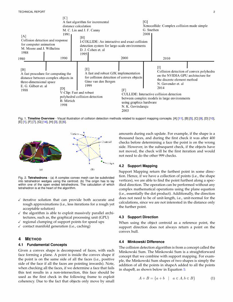
Fig. 2. Tetrahedrons - (a) A complex convex mesh can be subdividedinto tetrahedron wedges using the centroid. (b) The origin has to laywithin one of the open ended tetrahedrons. The calculation of whichtetrahedron is at the heart of the algorithm.
X iterative solution that can provide both accurate andrough approximations (i.e., less iterations for a rough yetacceptable solution)
X the algorithm is able to exploit massively parallel archi-tectures, such as, the graphical processing unit (GPU)
X regional clumping of support points for speed upsX contact manifold generation (i.e., caching)
4 METHOD
4.1 Fundamental ConceptsGiven a convex shape is decomposed of faces, with eachface forming a plane. A point is inside the convex shape ifthe point is on the same side of all the faces (i.e., positiveside of the face if all the faces are pointing inwards). Note,when checking all the faces, if we determine a face that failsthis test results in a non-intersection, this face should beused as the first check in the following frame to exploitcoherency. Due to the fact that objects only move by small
amounts during each update. For example, if the shape is athousand faces, and during the first check it was after 400checks before determining a face the point is on the wrongside. However, in the subsequent check, if the objects havenot moved, the check will be the first iteration and wouldnot need to do the other 999 checks.
4.2 Support MappingSupport Mapping return the farthest point in some direc-tion. Hence, if we have a collection of points (i.e., the shapevertices), we are able to find the point furthest along a spec-ified direction. The operation can be performed without anycomplex mathematical operations using the plane equation(i.e., essentially the dot product). Additionally, the directiondoes not need to be of unit-length, i.e., unit-normal for thecalculations, since we are not interested in the distance onlythe further point.
4.3 Support DirectionWhen using the object centroid as a reference point, thesupport direction does not always return a point on theconvex hull.
4.4 Minkowski DifferenceThe collision detection algorithm is from a concept called theMinkowski Sum. The Minkowski Sum is a straightforwardconcept that we combine with support mapping. For exam-ple, the Minkowski Sum shapes of two shapes is simply theaddition of all the points in shapeA added to all the pointsin shapeB, as shown below in Equation 1:
A+B = {a+ b | a ∈ A, b ∈ B} (1)
TECHNICAL REPORT 3
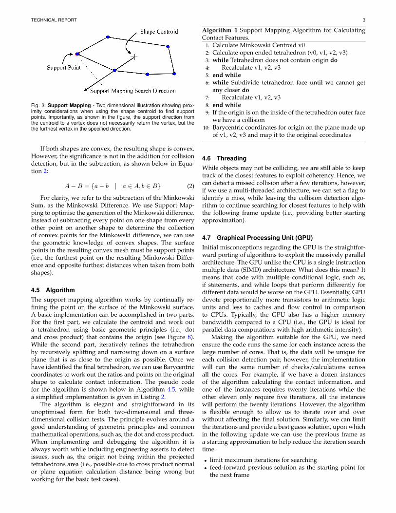
Fig. 3. Support Mapping - Two dimensional illustration showing prox-imity considerations when using the shape centroid to find supportpoints. Importantly, as shown in the figure, the support direction fromthe centroid to a vertex does not necessarily return the vertex, but thethe furthest vertex in the specified direction.
If both shapes are convex, the resulting shape is convex.However, the significance is not in the addition for collisiondetection, but in the subtraction, as shown below in Equa-tion 2:
A−B = {a− b | a ∈ A, b ∈ B} (2)
For clarity, we refer to the subtraction of the MinkowskiSum, as the Minkowski Difference. We use Support Map-ping to optimise the generation of the Minkowski difference.Instead of subtracting every point on one shape from everyother point on another shape to determine the collectionof convex points for the Minkowski difference, we can usethe geometric knowledge of convex shapes. The surfacepoints in the resulting convex mesh must be support points(i.e., the furthest point on the resulting Minkowski Differ-ence and opposite furthest distances when taken from bothshapes).
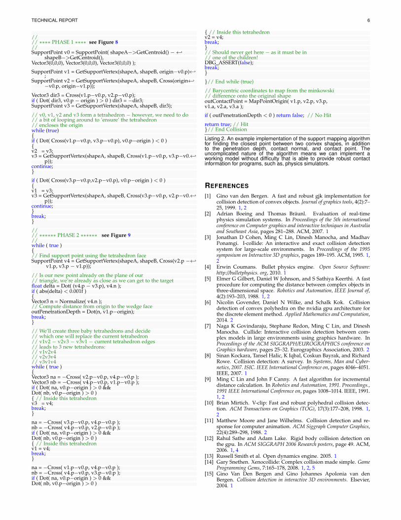
4.5 AlgorithmThe support mapping algorithm works by continually re-fining the point on the surface of the Minkowski surface.A basic implementation can be accomplished in two parts.For the first part, we calculate the centroid and work outa tetrahedron using basic geometric principles (i.e., dotand cross product) that contains the origin (see Figure 8).While the second part, iteratively refines the tetrahedronby recursively splitting and narrowing down on a surfaceplane that is as close to the origin as possible. Once wehave identified the final tetrahedron, we can use Barycentriccoordinates to work out the ratios and points on the originalshape to calculate contact information. The pseudo codefor the algorithm is shown below in Algorithm 4.5, whilea simplified implementation is given in Listing 2.
The algorithm is elegant and straightforward in itsunoptimised form for both two-dimensional and three-dimensional collision tests. The principle evolves around agood understanding of geometric principles and commonmathematical operations, such as, the dot and cross product.When implementing and debugging the algorithm it isalways worth while including engineering asserts to detectissues, such as, the origin not being within the projectedtetrahedrons area (i.e., possible due to cross product normalor plane equation calculation distance being wrong butworking for the basic test cases).
Algorithm 1 Support Mapping Algorithm for CalculatingContact Features.
1: Calculate Minkowski Centroid v02: Calculate open ended tetrahedron (v0, v1, v2, v3)3: while Tetrahedron does not contain origin do4: Recalculate v1, v2, v35: end while6: while Subdivide tetrahedron face until we cannot get
any closer do7: Recalculate v1, v2, v38: end while9: If the origin is on the inside of the tetrahedron outer face
we have a collision10: Barycentric coordinates for origin on the plane made up
of v1, v2, v3 and map it to the original coordinates
4.6 ThreadingWhile objects may not be colliding, we are still able to keeptrack of the closest features to exploit coherency. Hence, wecan detect a missed collision after a few iterations, however,if we use a multi-threaded architecture, we can set a flag toidentify a miss, while leaving the collision detection algo-rithm to continue searching for closest features to help withthe following frame update (i.e., providing better startingapproximation).
4.7 Graphical Processing Unit (GPU)Initial misconceptions regarding the GPU is the straightfor-ward porting of algorithms to exploit the massively parallelarchitecture. The GPU unlike the CPU is a single instructionmultiple data (SIMD) architecture. What does this mean? Itmeans that code with multiple conditional logic, such as,if statements, and while loops that perform differently fordifferent data would be worse on the GPU. Essentially, GPUdevote proportionally more transistors to arithmetic logicunits and less to caches and flow control in comparisonto CPUs. Typically, the GPU also has a higher memorybandwidth compared to a CPU (i.e., the GPU is ideal forparallel data computations with high arithmetic intensity).
Making the algorithm suitable for the GPU, we needensure the code runs the same for each instance across thelarge number of cores. That is, the data will be unique foreach collision detection pair, however, the implementationwill run the same number of checks/calculations acrossall the cores. For example, if we have a dozen instancesof the algorithm calculating the contact information, andone of the instances requires twenty iterations while theother eleven only require five iterations, all the instanceswill perform the twenty iterations. However, the algorithmis flexible enough to allow us to iterate over and overwithout affecting the final solution. Similarly, we can limitthe iterations and provide a best guess solution, upon whichin the following update we can use the previous frame asa starting approximation to help reduce the iteration searchtime.
• limit maximum iterations for searching• feed-forward previous solution as the starting point for
the next frame
TECHNICAL REPORT 4
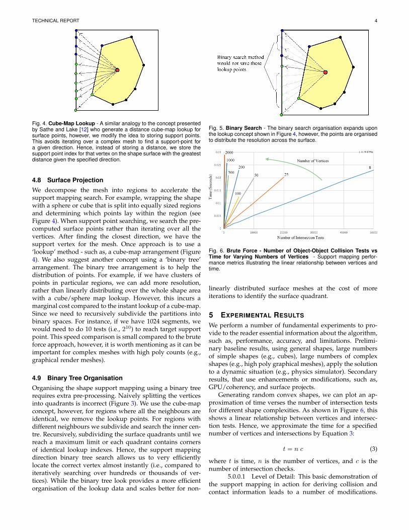
Fig. 4. Cube-Map Lookup - A similar analogy to the concept presentedby Sathe and Lake [12] who generate a distance cube-map lookup forsurface points, however, we modify the idea to storing support points.This avoids iterating over a complex mesh to find a support-point fora given direction. Hence, instead of storing a distance, we store thesupport point index for that vertex on the shape surface with the greatestdistance given the specified direction.
4.8 Surface ProjectionWe decompose the mesh into regions to accelerate thesupport mapping search. For example, wrapping the shapewith a sphere or cube that is split into equally sized regionsand determining which points lay within the region (seeFigure 4). When support point searching, we search the pre-computed surface points rather than iterating over all thevertices. After finding the closest direction, we have thesupport vertex for the mesh. Once approach is to use a‘lookup’ method - such as, a cube-map arrangement (Figure4). We also suggest another concept using a ‘binary tree’arrangement. The binary tree arrangement is to help thedistribution of points. For example, if we have clusters ofpoints in particular regions, we can add more resolution,rather than linearly distributing over the whole shape areawith a cube/sphere map lookup. However, this incurs amarginal cost compared to the instant lookup of a cube-map.Since we need to recursively subdivide the partitions intobinary spaces. For instance, if we have 1024 segments, wewould need to do 10 tests (i.e., 210) to reach target supportpoint. This speed comparison is small compared to the bruteforce approach, however, it is worth mentioning as it can beimportant for complex meshes with high poly counts (e.g.,graphical render meshes).
4.9 Binary Tree OrganisationOrganising the shape support mapping using a binary treerequires extra pre-processing. Naively splitting the verticesinto quadrants is incorrect (Figure 3). We use the cube-mapconcept, however, for regions where all the neighbours areidentical, we remove the lookup points. For regions withdifferent neighbours we subdivide and search the inner cen-tre. Recursively, subdividing the surface quadrants until wereach a maximum limit or each quadrant contains cornersof identical lookup indexes. Hence, the support mappingdirection binary tree search allows us to very efficientlylocate the correct vertex almost instantly (i.e., compared toiteratively searching over hundreds or thousands of ver-tices). While the binary tree look provides a more efficientorganisation of the lookup data and scales better for non-
Fig. 5. Binary Search - The binary search organisation expands uponthe lookup concept shown in Figure 4, however, the points are organisedto distribute the resolution across the surface.
Fig. 6. Brute Force - Number of Object-Object Collision Tests vsTime for Varying Numbers of Vertices - Support mapping perfor-mance metrics illustrating the linear relationship between vertices andtime.
linearly distributed surface meshes at the cost of moreiterations to identify the surface quadrant.
5 EXPERIMENTAL RESULTS
We perform a number of fundamental experiments to pro-vide to the reader essential information about the algorithm,such as, performance, accuracy, and limitations. Prelimi-nary baseline results, using general shapes, large numbersof simple shapes (e.g., cubes), large numbers of complexshapes (e.g., high poly graphical meshes), apply the solutionto a dynamic situation (e.g., physics simulator). Secondaryresults, that use enhancements or modifications, such as,GPU/coherency, and surface projects.
Generating random convex shapes, we can plot an ap-proximation of time verses the number of intersection testsfor different shape complexities. As shown in Figure 6, thisshows a linear relationship between vertices and intersec-tion tests. Hence, we approximate the time for a specifiednumber of vertices and intersections by Equation 3:
t = n c (3)
where t is time, n is the number of vertices, and c is thenumber of intersection checks.
5.0.0.1 Level of Detail: This basic demonstration ofthe support mapping in action for deriving collision andcontact information leads to a number of modifications.
TECHNICAL REPORT 5
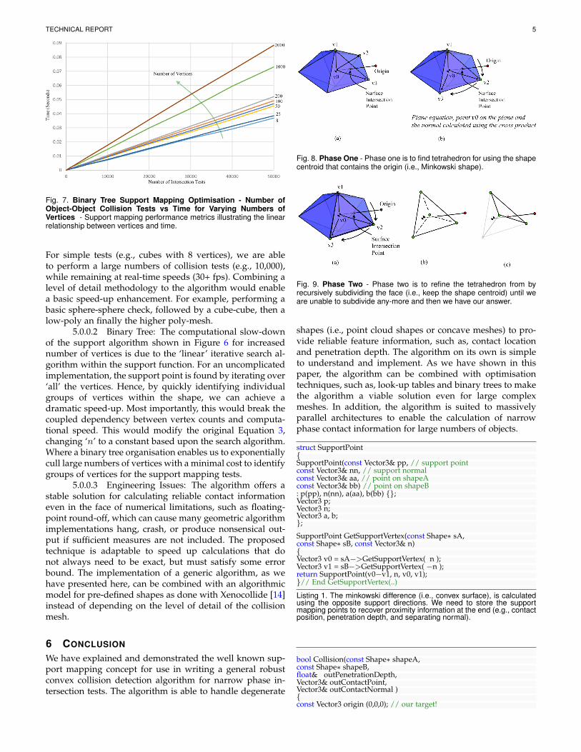
Fig. 7. Binary Tree Support Mapping Optimisation - Number ofObject-Object Collision Tests vs Time for Varying Numbers ofVertices - Support mapping performance metrics illustrating the linearrelationship between vertices and time.
For simple tests (e.g., cubes with 8 vertices), we are ableto perform a large numbers of collision tests (e.g., 10,000),while remaining at real-time speeds (30+ fps). Combining alevel of detail methodology to the algorithm would enablea basic speed-up enhancement. For example, performing abasic sphere-sphere check, followed by a cube-cube, then alow-poly an finally the higher poly-mesh.
5.0.0.2 Binary Tree: The computational slow-downof the support algorithm shown in Figure 6 for increasednumber of vertices is due to the ‘linear’ iterative search al-gorithm within the support function. For an uncomplicatedimplementation, the support point is found by iterating over‘all’ the vertices. Hence, by quickly identifying individualgroups of vertices within the shape, we can achieve adramatic speed-up. Most importantly, this would break thecoupled dependency between vertex counts and computa-tional speed. This would modify the original Equation 3,changing ‘n’ to a constant based upon the search algorithm.Where a binary tree organisation enables us to exponentiallycull large numbers of vertices with a minimal cost to identifygroups of vertices for the support mapping tests.
5.0.0.3 Engineering Issues: The algorithm offers astable solution for calculating reliable contact informationeven in the face of numerical limitations, such as floating-point round-off, which can cause many geometric algorithmimplementations hang, crash, or produce nonsensical out-put if sufficient measures are not included. The proposedtechnique is adaptable to speed up calculations that donot always need to be exact, but must satisfy some errorbound. The implementation of a generic algorithm, as wehave presented here, can be combined with an algorithmicmodel for pre-defined shapes as done with Xenocollide [14]instead of depending on the level of detail of the collisionmesh.
6 CONCLUSION
We have explained and demonstrated the well known sup-port mapping concept for use in writing a general robustconvex collision detection algorithm for narrow phase in-tersection tests. The algorithm is able to handle degenerate
Fig. 8. Phase One - Phase one is to find tetrahedron for using the shapecentroid that contains the origin (i.e., Minkowski shape).
Fig. 9. Phase Two - Phase two is to refine the tetrahedron from byrecursively subdividing the face (i.e., keep the shape centroid) until weare unable to subdivide any-more and then we have our answer.
shapes (i.e., point cloud shapes or concave meshes) to pro-vide reliable feature information, such as, contact locationand penetration depth. The algorithm on its own is simpleto understand and implement. As we have shown in thispaper, the algorithm can be combined with optimisationtechniques, such as, look-up tables and binary trees to makethe algorithm a viable solution even for large complexmeshes. In addition, the algorithm is suited to massivelyparallel architectures to enable the calculation of narrowphase contact information for large numbers of objects.
struct SupportPoint{SupportPoint(const Vector3& pp, // support pointconst Vector3& nn, // support normalconst Vector3& aa, // point on shapeAconst Vector3& bb) // point on shapeB: p(pp), n(nn), a(aa), b(bb) {};Vector3 p;Vector3 n;Vector3 a, b;};SupportPoint GetSupportVertex(const Shape∗ sA,const Shape∗ sB, const Vector3& n){Vector3 v0 = sA−>GetSupportVertex( n );Vector3 v1 = sB−>GetSupportVertex( −n );return SupportPoint(v0−v1, n, v0, v1);}// End GetSupportVertex(..)
Listing 1. The minkowski difference (i.e., convex surface), is calculatedusing the opposite support directions. We need to store the supportmapping points to recover proximity information at the end (e.g., contactposition, penetration depth, and separating normal).
bool Collision(const Shape∗ shapeA,const Shape∗ shapeB,float& outPenetrationDepth,Vector3& outContactPoint,Vector3& outContactNormal ){const Vector3 origin (0,0,0); // our target!
TECHNICAL REPORT 6
//// ∗∗∗∗ PHASE 1 ∗∗∗∗ see Figure 8//SupportPoint v0 = SupportPoint( shapeA−>GetCentroid() −←↩
shapeB−>GetCentroid(),Vector3(0,0,0), Vector3(0,0,0), Vector3(0,0,0) );
SupportPoint v1 = GetSupportVertex(shapeA, shapeB, origin−v0.p)←↩;
SupportPoint v2 = GetSupportVertex(shapeA, shapeB, Cross(origin←↩−v0.p, origin−v1.p));
Vector3 dir3 = Cross(v1.p−v0.p, v2.p−v0.p);if ( Dot( dir3, v0.p − origin ) > 0 ) dir3 = −dir3;SupportPoint v3 = GetSupportVertex(shapeA, shapeB, dir3);
// v0, v1, v2 and v3 form a tetrahedron − however, we need to do// a bit of looping around to ’ensure’ the tetrahedron// encloses the originwhile (true){if ( Dot( Cross(v1.p−v0.p, v3.p−v0.p), v0.p−origin ) < 0 ){v2 = v3;v3 = GetSupportVertex(shapeA, shapeB, Cross(v1.p−v0.p, v3.p−v0.←↩
p));continue;}if ( Dot( Cross(v3.p−v0.p,v2.p−v0.p), v0.p−origin ) < 0 ){v1 = v3;v3 = GetSupportVertex(shapeA, shapeB, Cross(v3.p−v0.p, v2.p−v0.←↩
p));continue;}break;}//// ∗∗∗∗∗∗ PHASE 2 ∗∗∗∗∗∗ see Figure 9//while ( true ){// Find support point using the tetrahedron faceSupportPoint v4 = GetSupportVertex(shapeA, shapeB, Cross(v2.p −←↩
v1.p, v3.p − v1.p));
// Is our new point already on the plane of our// triangle, we’re already as close as we can get to the targetfloat delta = Dot( (v4.p − v3.p), v4.n );if ( abs(delta) < 0.001f ){Vector3 n = Normalize( v4.n );// Compute distance from origin to the wedge faceoutPenetrationDepth = Dot(n, v1.p−origin);break;}// We’ll create three baby tetrahedrons and decide// which one will replace the current tetrahedron// v1v2 − v2v3 − v3v1 − current tetrahedron edges// leads to 3 new tetrahedrons:// v1v2v4// v2v3v4// v3v1v4while ( true ){Vector3 na = −Cross( v2.p−v0.p, v4.p−v0.p );Vector3 nb = −Cross( v4.p−v0.p, v1.p−v0.p );if ( Dot( na, v0.p−origin ) > 0 &&Dot( nb, v0.p−origin ) > 0 ){ // Inside this tetrahedronv3 = v4;break;}na = −Cross( v3.p−v0.p, v4.p−v0.p );nb = −Cross( v4.p−v0.p, v2.p−v0.p );if ( Dot( na, v0.p−origin ) > 0 &&Dot( nb, v0.p−origin ) > 0 ){ // Inside this tetrahedronv1 = v4;break;}na = −Cross( v1.p−v0.p, v4.p−v0.p );nb = −Cross( v4.p−v0.p, v3.p−v0.p );if ( Dot( na, v0.p−origin ) > 0 &&Dot( nb, v0.p−origin ) > 0 )
{ // Inside this tetrahedronv2 = v4;break;}// Should never get here − as it must be in// one of the children!DBG ASSERT(false);break;}
}// End while (true)
// Barycentric coordinates to map from the minkowski// difference onto the original shapeoutContactPoint = MapPointOrigin( v1.p, v2.p, v3.p,v1.a, v2.a, v3.a );
if ( outPenetrationDepth < 0 ) return false; // No Hit
return true; // Hit}// End Collision
Listing 2. An example implementation of the support mapping algorithmfor finding the closest point between two convex shapes, in additionto the penetration depth, contact normal, and contact point. Theuncomplicated nature of the algorithm means we can implement aworking model without difficulty that is able to provide robust contactinformation for programs, such as, physics simulators.
REFERENCES
[1] Gino van den Bergen. A fast and robust gjk implementation forcollision detection of convex objects. Journal of graphics tools, 4(2):7–25, 1999. 1, 2
[2] Adrian Boeing and Thomas Braunl. Evaluation of real-timephysics simulation systems. In Proceedings of the 5th internationalconference on Computer graphics and interactive techniques in Australiaand Southeast Asia, pages 281–288. ACM, 2007. 1
[3] Jonathan D Cohen, Ming C Lin, Dinesh Manocha, and MadhavPonamgi. I-collide: An interactive and exact collision detectionsystem for large-scale environments. In Proceedings of the 1995symposium on Interactive 3D graphics, pages 189–195. ACM, 1995. 1,2
[4] Erwin Coumans. Bullet physics engine. Open Source Software:http://bulletphysics. org, 2010. 1
[5] Elmer G Gilbert, Daniel W Johnson, and S Sathiya Keerthi. A fastprocedure for computing the distance between complex objects inthree-dimensional space. Robotics and Automation, IEEE Journal of,4(2):193–203, 1988. 1, 2
[6] Nicolin Govender, Daniel N Wilke, and Schalk Kok. Collisiondetection of convex polyhedra on the nvidia gpu architecture forthe discrete element method. Applied Mathematics and Computation,2014. 2
[7] Naga K Govindaraju, Stephane Redon, Ming C Lin, and DineshManocha. Cullide: Interactive collision detection between com-plex models in large environments using graphics hardware. InProceedings of the ACM SIGGRAPH/EUROGRAPHICS conference onGraphics hardware, pages 25–32. Eurographics Association, 2003. 2
[8] Sinan Kockara, Tansel Halic, K Iqbal, Coskun Bayrak, and RichardRowe. Collision detection: A survey. In Systems, Man and Cyber-netics, 2007. ISIC. IEEE International Conference on, pages 4046–4051.IEEE, 2007. 1
[9] Ming C Lin and John F Canny. A fast algorithm for incrementaldistance calculation. In Robotics and Automation, 1991. Proceedings.,1991 IEEE International Conference on, pages 1008–1014. IEEE, 1991.1, 2
[10] Brian Mirtich. V-clip: Fast and robust polyhedral collision detec-tion. ACM Transactions on Graphics (TOG), 17(3):177–208, 1998. 1,2
[11] Matthew Moore and Jane Wilhelms. Collision detection and re-sponse for computer animation. ACM Siggraph Computer Graphics,22(4):289–298, 1988. 2
[12] Rahul Sathe and Adam Lake. Rigid body collision detection onthe gpu. In ACM SIGGRAPH 2006 Research posters, page 49. ACM,2006. 1, 4
[13] Russell Smith et al. Open dynamics engine. 2005. 1[14] Gary Snethen. Xenocollide: Complex collision made simple. Game
Programming Gems, 7:165–178, 2008. 1, 2, 5[15] Gino Van Den Bergen and Gino Johannes Apolonia van den
Bergen. Collision detection in interactive 3D environments. Elsevier,2004. 1