technical requirements and work instructions for minor
TRANSCRIPT

Minor Works sewer Technical requirements and work instructions
Document current at DD Month YYYY Page 0
Technical requirements and Work Instructions for Minor Works (sewer)
Version 4 - November 2015

Sydney Water – Technical requirements and Work Instructions for Minor Works (sewer)
Version 4 - November 2015 Page 1
Change history
Version Key changes Prepared by Date Approved for use
1 Original Issue to replace abbreviated standard specification for the construction of Minor Works (sewer) dated March 1997
FM, WK, BN Aug 2004
BN
2 Changes to scope, format of work instructions and drawings
WK, MH, BN July 2005
BN
3 Changes to scope, inclusion of Leak Tight Sewer specification property connection arrangement, and general revision
HP, LS Sept 2015
KW
4 Change Quick Check references to Sydney Water Tap inTM
BH, HP Nov 2015
KW

Sydney Water – Technical requirements and Work Instructions for Minor Works (sewer)
Version 4 - November 2015 Page 2
Definitions 3
Abbreviations 4
1. Introduction 5
2. Scope of the Minor Works (sewer) process 5
3. Complementary documents 7
4. Planning 7
5. Soffit requirement and servicing below ground fixtures(such as in basements) 8
5.1 Soffit 8 5.2 Servicing below ground fixtures (such as in basements) 9
6. Products and materials 9
7. Excavation 97.1 Dial Before You Dig 9 7.2 Work site assessment 10 7.3 Excavation under roadways, driveways and improved surfaces 11 7.4 Support of excavations 11 7.5 Excavation in root zones 11 7.6 Excavation plant and tools 12 7.7 Topsoil 12 7.8 Disposal of excavated material 12 7.9 Blasting 12
8. Trench filling and compaction 128.1 Placement and compaction of trench fill 12 8.2 Removal of trench supports 12
9. Sealing disused points of connection 13
10. Surface restoration 13
11. Final inspection 13
12. Work As Constructed details 13
13. Work Instructions and Drawings 1413.1 Work Instruction – Investigate site 14 13.2 Work Instruction – Install junction 17 13.3 Work Instruction - Install pipework/riser for property connection 17 13.4 Work Instruction - Construct property connection sewer 17 13.5 Work Instruction - Concrete encase sewer 20 13.6 Work Instruction - Replace pipe 20
Sydney Water – Technical requirements and Work Instructions for Minor Works (sewer)
Version 4 - November 2015 Page 3
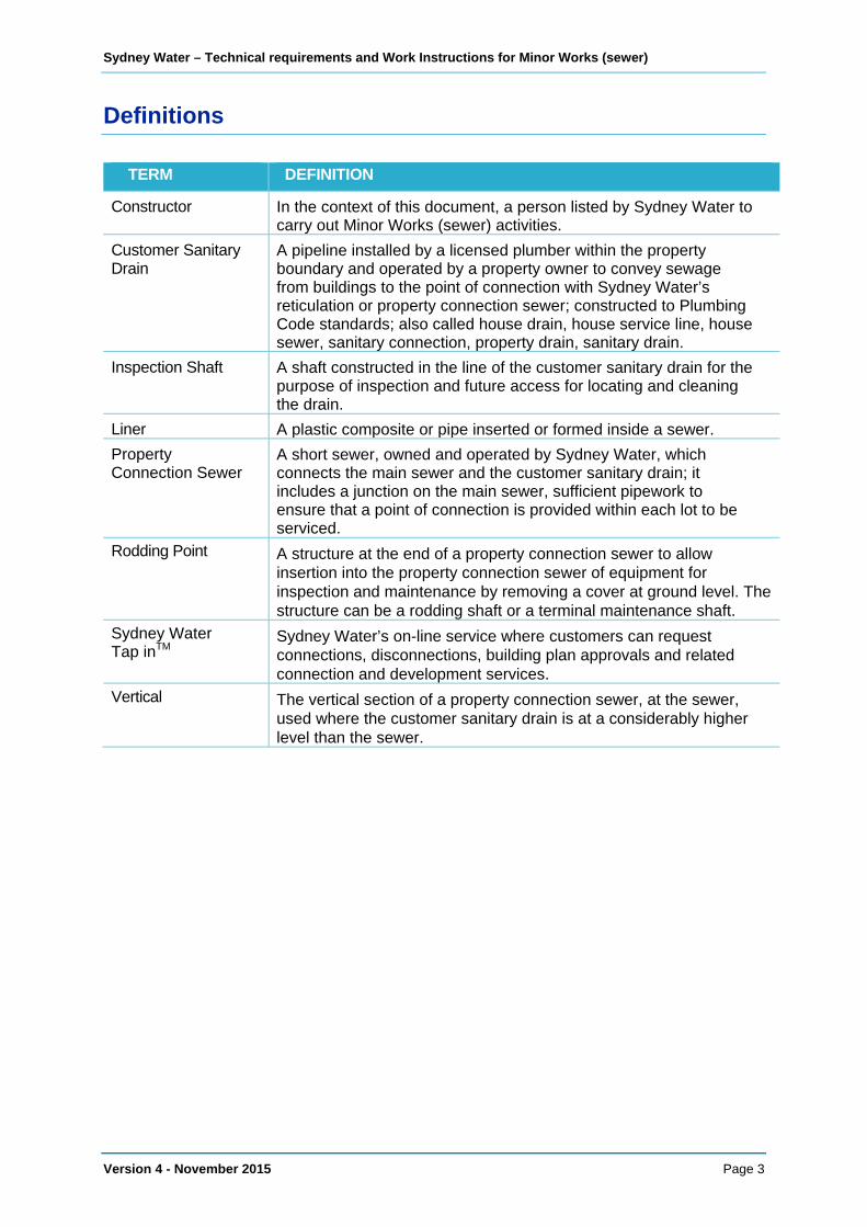
Definitions
TERM DEFINITION
Constructor In the context of this document, a person listed by Sydney Water to carry out Minor Works (sewer) activities.
Customer Sanitary Drain
A pipeline installed by a licensed plumber within the property boundary and operated by a property owner to convey sewage from buildings to the point of connection with Sydney Water’s reticulation or property connection sewer; constructed to Plumbing Code standards; also called house drain, house service line, house sewer, sanitary connection, property drain, sanitary drain.
Inspection Shaft A shaft constructed in the line of the customer sanitary drain for the purpose of inspection and future access for locating and cleaning the drain.
Liner A plastic composite or pipe inserted or formed inside a sewer. Property Connection Sewer
A short sewer, owned and operated by Sydney Water, which connects the main sewer and the customer sanitary drain; it includes a junction on the main sewer, sufficient pipework to ensure that a point of connection is provided within each lot to be serviced.
Rodding Point A structure at the end of a property connection sewer to allow insertion into the property connection sewer of equipment for inspection and maintenance by removing a cover at ground level. The structure can be a rodding shaft or a terminal maintenance shaft.
Sydney Water Tap inTM
Sydney Water’s on-line service where customers can request connections, disconnections, building plan approvals and related connection and development services.
Vertical The vertical section of a property connection sewer, at the sewer, used where the customer sanitary drain is at a considerably higher level than the sewer.

Sydney Water – Technical requirements and Work Instructions for Minor Works (sewer)
Version 4 - November 2015 Page 4
Abbreviations
ABBREVIATION INTERPRETATION
AC asbestos cement
AS Australian Standard
CI cast iron
CCTV closed-circuit colour television
CSD customer sanitary drain
DI ductile iron
DN nominal size
IS inspection shaft
kPa kilopascal
MH maintenance hole
MS maintenance shaft
OD outside diameter
PCS property connection sewer
PE polyethylene
PP polypropylene
PVC polyvinylchloride
PVC-U polyvinylchloride-unplasticised
RP rodding point
RRJ rubber ring joint
SCJ solvent cement joint
SS stainless steel
TMS terminal maintenance shaft
VC vitrified clay
WSC Water Servicing Coordinator

Sydney Water – Technical requirements and Work Instructions for Minor Works (sewer)
Version 4 - November 2015 Page 5
1. Introduction
This document sets out technical requirements and work instructions for construction activities allowed under the Minor Works (sewer) process. It includes both mandatory requirements and informative statements. The informative text (shown in italics) has been provided to allow a better understanding of the mandatory requirements. Documents related to this technical specification are listed in Section 3.
If difficulties are encountered at any stage during the conduct of work, contact the WSC or Sydney Water (Phone 13 20 90) as appropriate.
2. Scope of the Minor Works (sewer) process
NOTE: There may be occasions where works are initiated but are later found to be beyond the scope for the level of Constructor or have other complexities that are beyond the scope of Minor Works. In these instances the WSC or Sydney Water may require the works to be completed by a Constructor with appropriate capability and/or managed under a different process.
The scope of activities allowed under Minor Works (sewer) is outlined below:
Scope for ‘MS’ listed Constructors
Works relating to gravity sewers of size ≤DN 225 and depth ≤2.5 metres (measured from the invert of the sewer to the ground surface) and limited to:
• inserting junctions/property connection arrangements into existing VC and PVC sewers
• constructing PCSs of length not greater than 12 metres measured along the axis of thePCS from the centreline of the sewer at the PCS connection point to the centreline ofthe furthest riser for the IS or RP. Configurations may include a PCS off another PCS,extension of an existing PCS on line and grade or a PCS off an existing CSD inlet at aMH (see NOTES 1 and 2)
• constructing extensions of existing sewers on line and grade of length not greater than 12metres (measured along the axis of the extension from the end of the existing sewer tothe centreline of the TMS), where justification for extension has been accepted by SydneyWater (see NOTES 1 and 3)
• concrete encasing up to 25 metres of an existing VC or PVC sewer
• replacing up to 25 metres of existing VC or PVC sewer as a precursor to concreteencasement
• sealing points of connection to Sydney Water’s sewer.

Sydney Water – Technical requirements and Work Instructions for Minor Works (sewer)
Version 4 - November 2015 Page 6
Scope for ‘S1’ and ‘S2’ listed Constructors
Works beyond the scope of MS listed constructors must be performed by S1 and S2 listed constructors (see Note 4). The scope is extended to works relating to gravity sewers of size ≤DN 225 and depth ≤6.0 metres (measured from the invert of the sewer to the ground surface) and limited to:
• inserting junctions/property connection arrangements into existing VC and PVC sewers
• constructing PCSs of length not greater than 25 metres measured along the axis of thePCS from the centreline of the sewer at the PCS connection point to the centreline ofthe furthest riser for the IS or RP. Configurations may include a PCS off another PCS,extension of an existing PCS on line and grade or a PCS off an existing CSD inlet at aMH (see NOTES 1 and 2)
• constructing extensions of existing sewers on line and grade of length not greater than25 metres (measured along the axis of the extension from the end of the existing sewerto the centreline of the TMS), where justification for extension has been accepted bySydney Water (see NOTES 1 and 3)
• concrete encasing an existing VC or PVC sewer. Concrete encasing an existing VC orPVC sewer of size > DN 225 and ≤ DN 300 where pipe replacement/flow management isnot required is also permitted
• replacing up to 25 metres of existing VC, PVC, CI or DI sewer as a precursor to concreteencasement
• sealing points of connection to Sydney Water’s sewer
• disusing PCSs and sewers of size ≤DN 300 (see NOTE 5).
NOTE 1: Sydney Water Tap inTM will only accept an application where the PCS or a sewer extension is proposed to be not greater than 12 metres. If the length is proposed to be greater than 12 metres, the application must be lodged through a WSC.
NOTE 2: Breaking into existing MHs for new connections is not permitted.
NOTE 3: Any proposal to extend a ‘dead-end’ sewer requires a detailed case to be provided to Sydney Water for consideration and approval before construction.
NOTE 4: Where the scope falls outside that for ‘MS’ listed constructors, the appropriate additional requirements of ‘WSA 02 Sewerage Code of Australia (Sydney Water Edition)’ and ‘Technical Specification for Leak Tight Sewer Systems (Sydney Water)’ will apply. Generally survey, design and compliance testing will not be required except where the WSC or Sydney Water, having considered risks relevant to the case, specifies requirements.
NOTE 5: Any proposal to disuse a sewer will require consultation with Sydney Water and may involve the submission of a detailed case and method prior to approval for construction.
NOTE 6: For purposes of these requirements, VC includes all types of earthenware and clay pipes.
The scope of Minor Works (sewer) does NOT include construction of PCSs, extension of sewers and concrete encasement of sewers in mine subsidence areas, however inserting junctions/property connection arrangements are permitted. For information on the location of mine subsidence areas, visit www.minesub.nsw.gov.au .

Sydney Water – Technical requirements and Work Instructions for Minor Works (sewer)
Version 4 - November 2015 Page 7
3. Complementary documents
The following documents complement these requirements and, with the exception of the Sewerage Code and the ‘Techincal guidelines: Building over and adjacent to pipe assets’, are available on the Providers page in the Plumbing, building & developing section of the Sydney Water website.
• Application package for listing as a water and/or wastewater infrastructureProvider for designers, constructors (Major & Minor Works) to the managing newdevelopment process
• Instructions to Constructors – Minor Works (sewer)• Instructions to Water Servicing Coordinators – Minor Works (sewer)• List of acceptable product specifications• List of approved non-standard products• Deemed to Comply drawings• Technical Specifications for Leak Tight Sewer Systems (Sydney Water)• WSA 02 Sewerage Code of Australia (Sydney Water Edition) (available from the
Water Services Association of Australia)• Technical guidelines: Building over and adjacent to pipe assets (available
on the Building over or next to assets page in the Plumbing, building & developing section of the Sydney Water website)
4. Planning
Plan the work adequately to address safety, minimise impact on the community and the environment and to ensure all materials, plant and equipment are appropriate for the task. Ensure overflow or uncontrolled release of sewage will not occur.
Any work involving cutting into or working directly on a Sydney Water sewer or diverting sewage flows must be completed within one calendar day.
If the work involves cutting into a sewer (including cutting an investigation hole to determine if a sewer is lined), treat the trench environment as a confined space. Ensure compliance with Sydney Water’s procedure ‘Confined Space Safety’ (refer to the Providers page in the Plumbing, building & developing section of the Sydney Water website).
For each project, determine requirements for controlling sewage flow before starting the work. Consider the potential impact of unpredicted wet weather and/or other surges in flow occurring after work has started. Do not attempt to work during heavy rain or when there is reasonable chance of heavy rain occurring during the course of the job. As necessary, contact Sydney Water to determine the susceptibility of the site to inflow/infiltration. Be prepared for flow variations from diurnal patterns and pumped discharges.
Determine junction/pipe size required to service expected flows from proposed development. Larger pipes may be required for properties with multiple dwellings or where pumped flow is expected. Refer to your WSC or Sydney Water’s Pump to Sewer application process. Information about the Pump to Sewer application process is available in the Getting Connected customer guide, on the Connections & disconnections page of the Sydney Water website.
Verify that the size, depth and pipe type of the sewer is within the scope of Minor Works (sewer) and, if the work requires construction of a PCS, that minimum cover requirements can be achieved (refer to Drawing MWS-200).
Sydney Water – Technical requirements and Work Instructions for Minor Works (sewer)
Version 4 - November 2015 Page 8
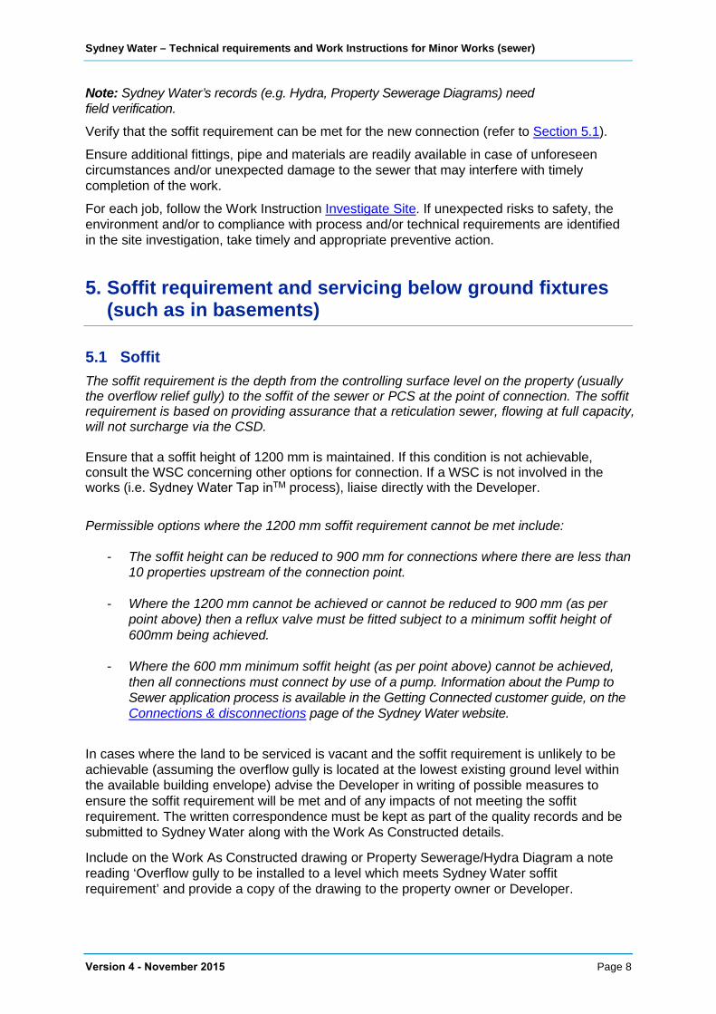
Note: Sydney Water’s records (e.g. Hydra, Property Sewerage Diagrams) need field verification. Verify that the soffit requirement can be met for the new connection (refer to Section 5.1).
Ensure additional fittings, pipe and materials are readily available in case of unforeseen circumstances and/or unexpected damage to the sewer that may interfere with timely completion of the work.
For each job, follow the Work Instruction Investigate Site. If unexpected risks to safety, the environment and/or to compliance with process and/or technical requirements are identified in the site investigation, take timely and appropriate preventive action.
5. Soffit requirement and servicing below ground fixtures(such as in basements)
5.1 Soffit The soffit requirement is the depth from the controlling surface level on the property (usually the overflow relief gully) to the soffit of the sewer or PCS at the point of connection. The soffit requirement is based on providing assurance that a reticulation sewer, flowing at full capacity, will not surcharge via the CSD.
Ensure that a soffit height of 1200 mm is maintained. If this condition is not achievable, consult the WSC concerning other options for connection. If a WSC is not involved in the works (i.e. Sydney Water Tap inTM process), liaise directly with the Developer.
Permissible options where the 1200 mm soffit requirement cannot be met include:
- The soffit height can be reduced to 900 mm for connections where there are less than 10 properties upstream of the connection point.
- Where the 1200 mm cannot be achieved or cannot be reduced to 900 mm (as per point above) then a reflux valve must be fitted subject to a minimum soffit height of 600mm being achieved.
- Where the 600 mm minimum soffit height (as per point above) cannot be achieved, then all connections must connect by use of a pump. Information about the Pump to Sewer application process is available in the Getting Connected customer guide, on the Connections & disconnections page of the Sydney Water website.
In cases where the land to be serviced is vacant and the soffit requirement is unlikely to be achievable (assuming the overflow gully is located at the lowest existing ground level within the available building envelope) advise the Developer in writing of possible measures to ensure the soffit requirement will be met and of any impacts of not meeting the soffit requirement. The written correspondence must be kept as part of the quality records and be submitted to Sydney Water along with the Work As Constructed details.
Include on the Work As Constructed drawing or Property Sewerage/Hydra Diagram a note reading ‘Overflow gully to be installed to a level which meets Sydney Water soffit requirement’ and provide a copy of the drawing to the property owner or Developer.

Sydney Water – Technical requirements and Work Instructions for Minor Works (sewer)
Version 4 - November 2015 Page 9
5.2 Servicing below ground fixtures (such as in basements) In cases where the land to be serviced will involve below ground fixtures such as in basements, consult a WSC for servicing solutions.
6. Products and materials
Use only products and materials that meet the specifications listed in Table 6.1 or that are listed by Sydney Water as ‘Acceptable Products’. The ‘List of acceptable product specifications’ and the ‘List of approved non-standard products’ are available on the Providers page in the Plumbing, building & developing section of the Sydney Water website.
Table 6.1* Product Specifications
Product Specification or product PVC-U pipes and fittings AS/NZS 1260, Class SN 8, Class SN 10
pipework/riser for property connection
VC pipe and fittings EN 295.1
Stainless steel oblique junction Wang sewer or Rapid sewer OB junction clamps or approved equivalent
Slip coupling (for ribbed PVC) AS/NZS 1260
Slip coupling (for plain wall PVC) AS/NZS 1260
Metal banded flexible coupling for VC and PVC (plain wall only)
AS 4327
Sealant (for lined sewers) Sikadur 31, Nitomortar EL-HB, Epirez 633, or approved equivalent
* Table 6.1 is not a comprehensive listing of product specifications.
7. Excavation
This section specifies general requirements for excavation undertaken for Minor Works activities. Additional requirements for specific activities are specified in the Work Instructions and Drawings.
7.1 Dial Before You Dig Determine the location and type of services in the area where work is to take place by contacting the ‘Dial Before You Dig’ service (visit www.1100.com.au or telephone 1100) and by other appropriate means.
Take precautions against the possibility that major and/or dangerous services may be located within private property.
Note: Dial Before You Dig does not usually provide information about property services.
Ensure plans and information from utility service owners are available on site to assist in locating, identifying and protecting services both before and throughout excavation and restoration activities.

Sydney Water – Technical requirements and Work Instructions for Minor Works (sewer)
Version 4 - November 2015 Page 10
Immediately report damage to any services, whether public or private, to the owner of the service.
New PCSs must have clearance from other services not less than (and preferably exceeding) those shown in Table 7.1.
The clearance must be measured between the two closest parts of the sewer and the other underground service e.g. collar to socket.
Table 7.1 Clearances between sewers and other underground services
Utility (Existing service) Minimum horizontal clearance (mm) for
new sewers ≤ DN300
Minimum vertical clearance1 (mm)
Sewers ≤DN 300 300 150 Sewers >DN 300 600 300
Gas mains 3003 1502/300 Telecommunication conduits and cables 3003 1502/300
Electricity conduits and cables 500 2252/300 Stormwater drains7 3003 1502 and 4/3004
Water mains 10005/600 5004 Kerbs 1506 150 (where practicable)
NOTES:
1. Vertical clearances apply when sewers cross one another, except in the case of water mains when a verticalseparation must always be maintained, even when the sewer and main are parallel. The sewer should always belocated below water mains to minimise the possibility of backflow contamination in the event of a water mainbreak.
2. A minimum vertical clearance of 300 mm applies if the size of the existing service is >DN 300.3. Clearances can be further reduced to 150 mm for distances up to 2 metres when passing installations such as
poles, pits and small structures, providing the structure is not destabilised in the process.4. Sewers should always cross under water mains and stormwater drains. If this requirement cannot be met, liaise
with the developer/property owner to engage a WSC for the development of a servicing solution and managementof the works. Where a sewer crosses a water main at or close to 90 degrees, the vertical clearance may bereduced to not less than 200 mm provided that the sewer is concrete encased and a 50 mm compressible materialis placed over the encasement. The encasement must not have any joints within 1000 mm either side of the watermain and must conform to Drawing MWS–300.
5. When the sewer is at the minimum vertical clearance below the water main (500 mm) maintain a minimumhorizontal clearance of 1000 mm. This minimum horizontal clearance can be progressively reduced to 600 mm asthe vertical clearance increases to 750 mm.
6. Clearance from kerbs must be measured from the nearest point of the kerb.7. A sewer to be constructed under an existing or proposed stormwater pipe or channel ≥DN 375 must be concrete
encased. The concrete encasement must extend at least one metre each side of the stormwater pipe or channel.Clearances between the sewer and other services must be measured from the outer surface of the concreteencasement.
7.2 Work site assessment Before starting excavation, re-assess the site, including obstacles such as underground services, overhead power cables and traffic management requirements and verify that proposed environmental and safety precautions are adequate.
Do not commence work until conditions comply with relevant confined space requirements.
Comply with recommendations and guidelines set out in the ‘Excavation work code of practice’ and ‘Construction work code of practice’ (available at www.workcover.nsw.gov.au).

Sydney Water – Technical requirements and Work Instructions for Minor Works (sewer)
Version 4 - November 2015 Page 11
Do not commence any excavation until all equipment and materials necessary to make the excavation safe are on site and available for use. Equipment and materials include all necessary fencing and barriers, as well as trench support systems.
Consider the need for a dilapidation survey.
7.3 Excavation under roadways, driveways and improved surfaces Where the construction of the works involve the opening of a road or footpath, it is the Constructor’s responsibility to obtain the consent of the relevant roads authority and abide by the conditions of consent as referred to in the Roads Act 1993 granted by the approving authority.
Written permission must be obtained from the relevant property owner(s) before commencing any excavation under or across improved surfaces.
If excavation is required across improved surfaces such as pavements, driveways, kerbs and gutters, or where the surfaces cannot be satisfactorily reinstated, assess constraints and, in consultation with a WSC if they are involved with the works, select an appropriate method (for example, boring).
For open excavation across improved surfaces, keep the trench width to the minimum allowed. Saw cut neat straight lines through bitumen, asphalt and concrete at least 150 mm beyond the outer limits of the required excavation. Remove pavers, blocks and bricks by hand, clean them and set them aside for later replacement.
7.4 Support of excavations Comply with all support requirements set out in the ‘Excavation work code of practice’, (available at www.workcover.nsw.gov.au). Particular attention is drawn to the following requirements for trench stability:
• Support, or bench, any trench of depth greater than 1.5 metres
• Where material is stored within the trench’s zone of influence, the height of the trenchto be used in determining the zone of influence must be the greater of:(a) the distance between the trench floor and the top of the stored material or(b) the height of the highest trench wall
• Support all trenches where trench walls are unstable. Consider all trenches 1.5metres and deeper to be unstable. In the event of uncertainty about any trench,obtain specialist engineering advice.
• For a trench of depth 1.5 metres or greater, ensure plant, traffic and materials do notencroach within 1 metre of the trench’s zone of influence, except where supportsystems are designed for these surcharge loads.
• Ensure that adjacent structures and services are not subject to disturbance by thetrench support system.
7.5 Excavation in root zones Take every precaution to ensure that no undue damage is caused to tree root systems from excavating. Consider excavating by hand or by boring to protect the root zone.
Sydney Water – Technical requirements and Work Instructions for Minor Works (sewer)
Version 4 - November 2015 Page 12
7.6 Excavation plant and tools Choose excavation plant and/or tools so that plant operation will minimise safety hazards, will not adversely impact on the environment and community and will not damage existing infrastructure and property.
7.7 Topsoil Where construction is to occur on grassed areas, remove turf sods and topsoil before excavating and set aside in an appropriate location for later use in restoring the site.
7.8 Disposal of excavated material Dispose of any excess material in accordance with the property owner’s requirements and with regard to environmental legislation.
7.9 Blasting Do not use blasting.
8. Trench filling and compaction
8.1 Placement and compaction of trench fill Before placing trench fill, ensure that pipe bedding fully supports the pipe and that pipe embedment material covers the crown of the pipe by at least 150 mm in non-trafficable areas and at least 300 mm in trafficable areas.
Where the filled trench will be subjected to traffic loading, the fill material must comply with the requirements of the road owner. In the absence of a directive, use one of the following:
• Compaction sand; or
• Fine crushed rock; or
• 75 mm crushed rock.
Ensure that trench fill is free of large clumps and debris and complies with requirements specified in the Drawings.
When placing trench fill, avoid impact loading of the sewer and/or junction. Place and compact trench fill in layers of approximately 300 mm. Do not use flooding compaction.
8.2 Removal of trench supports When removing, raising or withdrawing trench supports, prevent slips and falls and ensure that no damage, disturbance or displacement occurs to the pipe, fittings, geotextile filter fabric, pipe embedment and trench fill already installed. Ensure that all embedment and trench fill material located below such trench support and against native ground is progressively compacted as supports are withdrawn.
If agreed with the property owner, the trench support system may be left in place as permanent support. Where the property owner agrees to trench supports being left in place, cut off the support system at a depth at least 200 mm below the finished surface level required to satisfy structural and development requirements of the site.
Rectify all settlement occurring within 12 months of completion of work.

Sydney Water – Technical requirements and Work Instructions for Minor Works (sewer)
Version 4 - November 2015 Page 13
9. Sealing disused points of connection
Where constructing a new junction/property connection arrangement or a PCS results in an existing connection no longer being required, seal the redundant connection at the point of connection to Sydney Water’s system and in accordance with the pipe manufacturers’ recommendations.
10. Surface restoration
Unless otherwise authorised in writing by the owner of the disturbed property, replace or repair as near as practicable to the pre-construction condition all surfaces and/or improvements (for example shrubs, gardens, retaining walls, fences, pavements) which are disturbed or damaged during construction.
As soon as possible after completing trench backfill, relay turf sods and topsoil previously removed and set aside.
Immediately after trench backfilling and compaction, make safe and temporarily restore trafficable areas to a condition suitable for withstanding traffic loads. Maintain the temporary restoration until final restoration is completed. Where pavements and driveways require restoration or replacement, complete such work in consultation with the property owner and within one month of trench backfilling.
Restore bushland areas as near as practicable to their pre-construction state. Place previously stockpiled topsoil over the affected area and protect the site against erosion.
11. Final inspection
Arrange inspections as required (refer to ‘Instructions for Constructors – Minor Works (sewer)’). Rectify non-conformances.
Note: At its discretion, Sydney Water may conduct additional independent inspections of the work, including CCTV inspections.
12. Work As Constructed details
During progress of the work, legibly record all as-constructed details (including ties to enable location of work) in a manner which accurately shows the completed work.
For pipe replacement in lined sewers, record the type of lining found, location, length, material and stiffness of replacement pipes as well as differences in internal diameters.
Where the soffit requirement is unlikely to be achievable, provide the records set out in Section 5.1.
Provide the required Work As Constructed details and documents to Sydney Water or the WSC, as detailed in the relevant Provider Instruction.
Note: Any disused points of connection or disused sewers must be clearly marked on the WAC plan.

Sydney Water – Technical requirements and Work Instructions for Minor Works (sewer)
Version 4 - November 2015 Page 14
13. Work Instructions and Drawings
Any work involving cutting into or working directly on a Sydney Water sewer or diverting sewage flows must be completed within one calendar day.
Care must be taken to ensure that all works are constructed to prohibit the ingress of groundwater and stormwater for the life of the pipework.
The following Work Instructions and Drawings form part of the requirements and must be read in conjunction with the requirements:
Work Instruction title Drawing no. Drawing title
Investigate Site SEW-1150-S
SEW-1200
Sewer Symbols
Soil Classification Guidelines
Install Junction and pipework/riser for Property Connection
MWS-101
MWS-102
MWS-103
MWS-104
Install SS Junction – Unlined Sewer
Install SS Junction – Lined VC Sewer
Install Cut-in Junction – Unlined Sewer
Install Pipework/Riser for single property connection
Construct Property Connection Sewer
MWS-200
MWS-201
MWS-202
Construct PCS
Construct Rodding Point
Existing Vertical for PCS
Concrete Encase Sewer MWS-300 Concrete Encase Sewer
Replace Pipe MWS-400 Replace Pipe
13.1 Work Instruction – Investigate site
Scope This Work Instruction sets out technical requirements for site investigation as a first step in undertaking any and all work. The purpose of the investigation is to:
• identify site safety and environmental issues.
• as necessary, verify:
- location, depth, size and function of underground services, obstructions and that properties can be served by proposed sewer works
- that the soffit requirement relating to the lowest fitting on the property is achievable (refer to Section 5.1)
• identify sewer pipe material
• determine whether the sewer is lined
• identify impediments to the work (for example the sewer receives pumped flows or isencased).

Sydney Water – Technical requirements and Work Instructions for Minor Works (sewer)
Version 4 - November 2015 Page 15
Background To reduce infiltration into Sydney Water’s sewers and to increase the life of sewers, many older sewers have been lined.
Special methods may be necessary for undertaking Minor Works activities on sewers constructed from obsolete materials such as cast iron, or materials that do not conform to current design standards.
Sydney Water’s database (Hydra) may not accurately record pipe material and/or lining details. Consequently, as a first step in undertaking work, a site investigation is required to determine the sewer pipe material, if the sewer is lined and/or if unexpected features exist.
Constructors should be aware that, as a general rule:
• Sewers constructed of polyvinylchloride (PVC) are not lined.
• Some sewers constructed of vitrified clay (VC) are lined. The lining may also havesealed existing unused junctions.
• A relatively small number of sewers are constructed from alternative materials suchas asbestos cement (AC), cast iron (CI), ductile iron (DI) or concrete, and they mayhave been concrete encased at the intended location of a junction.
Sewer linings that may be encountered include:
• Folded and formed PVC
• Spiral-wound PVC
• Cured-in-place resin impregnated felt
• Folded and formed PE
• Plain PE
• Formed fibreglass.
Procedure Verify records Obtain services records (for example through Dial Before You Dig, sewer service diagram, Hydra) and verify the accuracy of records in the field.
Verify that the work site is not located in a mine subsidence area.
Site safety and environmental issues Assess site safety and environmental issues, develop appropriate documentation and execute requirements in accordance with relevant Provider Instructions.
If work involves cutting into the sewer, or in the event that the sewer is damaged, treat the excavation as a confined space.
Control sewage flow Ensure that appropriate measures can be implemented to control sewage flow, including any flows from sewage pumping stations and private pumping.
Ensure materials are available Ensure ready availability of additional fittings, pipe and materials that may be required in the event of unforeseen circumstances and/or unexpected damage to the sewer that may interfere with timely completion of the work.

Sydney Water – Technical requirements and Work Instructions for Minor Works (sewer)
Version 4 - November 2015 Page 16
Excavate to reveal sewer Taking extreme care to avoid damage to the sewer, excavate and expose a section of sewer at the proposed work location e.g. point of connection. If a Constructor who only has ‘MS’ listing finds that the depth of the sewer exceeds 2.5 metres, immediately cease work and contact the WSC involved in the case. For applications lodged through Sydney Water Tap inTM phone Sydney Water on 13 20 90. Ensure safety and other issues are addressed should the site need to be made available to others for inspection or further work.
Verify soffit requirement For a junction installation and/or and construction of a PCS, verify that the overflow level of the lowest actual and/or expected future drainage fitting (for example, overflow gully) on the property being connected is at least 1200 mm above the soffit of Sydney Water’s sewer at the point of connection. Where the requirement is not achievable and/or the land to be serviced is vacant, refer to Section 5.1.
Identify sewer material Clean and inspect the sewer to determine the pipe material. If the sewer pipe material is ductile iron, cast iron, PE, PP, asbestos cement or concrete, or if the sewer is concrete encased at the intended location of work, contact the WSC involved in the case. For applications lodged through Sydney Water Tap inTM phone Sydney Water on 13 20 90.
If the pipe material is PVC, proceed with work as appropriate and in accordance with relevant Work Instructions and Drawings.
If the pipe material is VC, for junction installations and pipe replacement continue as specified below to determine whether the sewer is lined.
Determine if sewer is lined If an existing junction is to be utilised to connect a PCS, carefully remove the cap and check that the inlet has not been sealed by a lining in the sewer. If it has been sealed, contact the WSC involved in the case. The condition of the junction and the difficulty of effectively cutting and sealing the liner through the arm of the junction may mean that junction/pipe replacement is required. Alternatively, the installer of the liner might be contracted to cut-out the inlet using job specific tools from within the sewer.
For new junction installations, mark the location of the proposed junction inlet on the surface of the sewer. Ensure the radial location of the inlet is suitable for either a CSD or a PCS connection.
For pipe replacement, identify and mark one or two appropriate points within the length to be replaced where investigation holes need to be cut in the sewer. Ensure the hole(s) are not more than 4 metres from either end of the section to be replaced, unless there is a nearby MH from where the lining status can be determined.
For new junction installations or pipe replacement, grind or cut a hole (approximately 100 mm x 100 mm) into the sewer at the location(s) previously marked. Prevent pieces cut from the sewer pipe from entering the sewer, or else retrieve them. Use suitable tools to grind or cut the pipe. Do not use hammers and chisels.
Inspect the inside of the sewer (via the cut hole) to determine whether the sewer is lined.
Measure and record the internal diameter of the sewer.
Adopt the appropriate Work Instruction and work method based on whether the sewer is lined or unlined.

Sydney Water – Technical requirements and Work Instructions for Minor Works (sewer)
Version 4 - November 2015 Page 17
13.2 Work Instruction – Install junction
Step 1: Investigate site Execute Work Instruction Investigate site.
Step 2: Install junction Select junction size to suit flows from the proposed development. The size for a typical residential property is to be 150 x 100 or 225 x 100. If the junction is to be used for a PCS to serve more than one property or a property with multiple dwellings, then the size is to be 150 x 150 or 225 x 150 or 225 x 225.
Install a junction in accordance with the relevant method/drawing referenced in the table below. Selection of an allowable method depends on the existing sewer or existing PCS size and material and if the sewer is lined (both determined by site investigation).
Selection of junction installation methods
Pipe Material Drawing
Unlined Sewer PVC - plain wall MWS-101
MWS-103 PVC – ribbed/profiled wall MWS-103
VC MWS-101
MWS-103
Lined Sewer VC MWS-102
13.3 Work Instruction - Install pipework/riser for property connection
Step 1: Install pipework/riser Install pipework/riser in accordance with Drawing MWS-104.
13.4 Work Instruction - Construct property connection sewer
Step 1: Investigate site Execute Work Instruction Investigate site.
Step 2: Construct PCS Existing sewer or PCS If the PCS will be constructed off an existing sewer or PCS, or if it will be an extension of an existing sewer or PCS on line and grade, construct a PCS in accordance with Drawing MWS-200. Some possible PCS configurations are shown in Figure 1.
Existing Vertical If the junction to which the PCS is to be connected is located on an existing PCS Vertical (see Drawing MWS-202) and is not in a trafficable area, obtain Sydney Water approval to proceed with constructing a PCS. Subject to approval, construct the PCS in accordance with Drawing MWS-200. This work is not permitted where the PCS Vertical is in a trafficable area.

Sydney Water – Technical requirements and Work Instructions for Minor Works (sewer)
Version 4 - November 2015 Page 18
Note: In assessing an application to construct a PCS from an existing Vertical, Sydney Water will consider aspects such as:
• The risk of interfering with an adjacent service (for example, if the sewer is not in theproperty to be served, or if two connections to the Vertical already exist)
• The condition of the Vertical and its connection to the reticulation sewer
• Whether the Vertical is connected to the reticulation sewer by means of a squarejunction (that is, the reticulation sewer may be at risk of damage if rodded via theVertical)
New Vertical A new Vertical is not permitted.
If the existing sewer and existing/new junction are in rock or an obstruction is found, provided the new sewer is not located in a trafficable area and subject to Sydney Water approval, the option exists under the minor works process for ‘S1’ and ‘S2’ listed constructors only to:
(a) first construct a MS in accordance with WSA 02 Sewerage Code of Australia (Sydney Water edition) and Technical Specification for Leak Tight Sewer Systems (Sydney Water) and then
(b) construct a PCS from the MS riser in accordance with Drawing MWS-200.
Obstruction If an underground obstruction exists in the proposed route of the PCS:
(a) Document details of function, depth and dimensions of obstruction.
(b) Undertake a risk assessment and record possible safety risks/hazards including possible damage to obstruction or property.
(c) Document proposed work method based on the concept of a typical PCS configuration for a single property (see next page) and Drawing MWS-104.
(d) Before adopting this option, submit obstruction details and proposed work method for WSC or Sydney Water approval.
(e) Construct PCS in accordance with approved work method and relevant drawings.
Step 3: Construct a Rodding Point Where a PCS will service more than one property, construct a RP at the upstream end in accordance with Drawing MWS–201.

Figure 1 Typical PCS configurations
The length of a PCS is measured along the axis of the PCS from the centreline of the existing sewer at the PCS connection point to the centerline of the furthest riser for the IS or RP. Some permitted PCS configurations are listed as follows (length limits shown are for “S1” and “S2” listed Constructors. Length limit for Constructors who only have “MS” listing is 12 m MAX):
For all configurations, a PCS shall provide a connection point within each property.
Each PCS shall have maintenance access from the surface at its upstream end. This access will be through the future inspection shaft to be completed by the plumbing licensee on each property. Depending on the configuration, a RP or TMS may also be required to be installed by the Constructor.
The RP for the on line and grade extension of a sewer shall be of TMS type.
RPs must be located within the properties being served by the new works. An exception may
be where the TMS of an on-line and grade sewer extension is in public land.
Sydney Water – Technical requirements and Work Instructions for Minor Works (sewer)
Version 4 - November 2015 Page 20
13.5 Work Instruction - Concrete encase sewer
Step 1: Investigate site Execute Work Instruction Investigate Site.
Step 2: Inspect pipes Before concrete encasing the sewer, consult with the WSC to arrange for them to inspect the existing pipes. Determine if any live, unused and/or disused junctions are within the length of sewer to be encased. Get direction from the WSC about actions to be taken for junctions.
Step 3: Replace defective pipes/relocate junctions Replace mortar-jointed VC, CI and DI pipes and, as directed by the WSC or as otherwise determined, replace defective pipes in accordance with Work Instruction Replace Pipe.
Remove, seal or otherwise treat junctions in accordance with Drawing MWS-300.
Step 4: Concrete encase pipes Concrete encase pipes in accordance with Drawing MWS-300.
13.6 Work Instruction - Replace pipe
Step 1: Investigate site As necessary, execute Work Instruction Investigate Site.
Step 2: Replace defective pipes As directed by the WSC or Sydney Water, or as otherwise determined, replace defective pipes in accordance with Drawing MWS-400.

MISCELLANEOUS SYMBOL STRUCTURE SYMBOL SURVEY MARKS
MAINTENANCE HOLE (ACCESS CHAMBER) • BENCH MARK .. LEVEL MARK ~ MAINTENANCE HOLE WITH OVERFLOW AND GAS CHECK a PERMANENT HARK IPHI [] PM 12345 g c__ STATE SURVEY MARK (SSMI [] SSM 6789 DUAL MAINTENANCE HOLES FOR OVERFLOW
ROCK MARK OR DRILL HOLE AND WING (DH&Wl ,
VENTSHAFT o ..... i MAINTENANCE HOLE WITH VENTSHAFT
GALVANISED IRON NAIL IN TREE QGIN
MS
BOUNDARY LINE MAINTENANCE SHAFT ©
vc VACUUM CHAMBER © FENCE -\-\-\-
TMS WALL IZZ ZZ ZZ ZZ ZZ ZI TERMINAL MAINTENANCE SHAFT @
lr RP
RODDING POINT • RETAINING WALL ON LINE (SECTION)
"'c_,\ VENTSHAFT (INDUCT OR EDUCT) 0
"'c_,t
• 0
BUILDING PROPOSED SEWER TO BE CONSTRUCTED ON ASSOCIATED PLANS ---·---
HOUSE ON LOT H EXISTING SEWER AND MAINTENANCE HOLE (IF HOUSE NUMBER IS SHOWN SYMBOL IS OMITTED) •
VACANT LOT v ~ CONCRETE ENCASEMENT (SECTION) FINISHED SURFACE LEVEL FSL r I
POSITION OF JUNCTION _/ / I
' -1 ' I
DIRECTION OF FLOW AND
~ POSITION OF PROPERTY CONNECTION SEWER (PCS)
Sydney RECOMMENDED SEWERAGE CODE WSA-02 NOT TO SCALE R. RIZZI
WATER for PROCESS LEADER WASTEWATER SYSTEllS SEW-1150-S APPROVED 28.03.03
SEWER SYMBOLS @COPYRIGHT B.NELSON
STATE DF NEW SOUTH WALES TlllOUGH SYDNEY far PROCESS LEADER ISSUED: 2003 I VERSION: 1 WATER CORPORATION. ALL AlfifTS RESERVED STAATES: ~ IWWiEIDT LETTER DETAILS OF VERSION I AMENDMENT APP'D DATE

PREPARING THE TEST AREA:
CONDUCT ALL NATIVE SOIL IDENTIFICATION TESTS ON A FRESHLY EXPOSED, DAMP, HAND TRIMMED AREA OF THE TRENCH WALL IN THE PIPE ZONE. TAKE CARE THAT THE SOIL SOIL CLASSIFICATION FIELD IDENTIFICATION TEST .6. AHBPkPa IN THE EXPOSED TEST AREA IS NOT COMPACTED OR LOOSENED DURING TRENCH EXCAVATION. IF THE SOIL IN THE TRENCH FLOOR AND WALL IS VERY DRY AT THE TIME THE TRENCH IS OPENED THEN FLOOD THE TEST AREA AND ALLOW TIME FOR THE WATER TO V[RY SOFT EASILY PENETRATED 40 mm WITH FIST. <50* BE ABSORBED BY THE SOIL BEFORE IT IS TRIMMED AND TESTED.
SOFT EASILY PENETRATED 40 mm WITH THUMB. <50* en ....I MODERATE EFFORT NEEDED TO PENETRATE <50* IDENTIFYING CLAY SOILS: 0 FIRM 30 mm WITH THUMB. en
A LUMP OF CLAY SOIL WILL BE DIFFICULT TO BREAK WHEN DRY. IT WILL BE STICKY AND ~ READILY INDENTED WITH THUMB BUT
NEED SOME EFFORT TO MOULD WITH THE FINGERS WHEN WET. CLAY WILL NOT WASH OFF STIFF PENETRATED ONLY WITH GREAT EFFORT.
50 EASILY. INDIVIDUAL CLAY PARTICLES ARE HARD TO SEE. (.)
VERY STIFF READILY INDENTED WITH THUMBNAIL. 100
TESTING CLAY SOILS: HARD INDENTED WITH DIFFICULTY BY THUMBNAIL. 200 CLAY SOILS ARE BEST TESTED IN THE WALL OF THE TRENCH. THE FIST, THE THUMB OR THE THUMBNAIL ARE USED TO DETERMINE THE CONSISTENCY (STRENGTH) OF THE CLAY ....I
w LOOSE CLEAN SAND TAKES FOOTPRINT MORE THAN 10 mm DEEP. <50* (SEE TABLE.) ~ C!) MEDIUM-DENSE
TAKES FOOTPRINT 3 mm TO 10 mm DEEP. 50 o!S CLEAN SAND
IDENTIFYING CLEAN SAND SOILS: Cl DENSE CLEAN SAND z TAKES FOOTPRINT LESS THAN 3 mm DEEP. 100 THE INDIVIDUAL GRAINS OF SAND WILL BE VISIBLE TO THE EYE. A LUMP OF CLEAN SAND, <( OR GRAVEL en
IF IT CAN BE PICKED UP AT ALL, WILL CRUMBLE WITH VERY LITTLE EFFORT. CLEAN SAND WASHES OFF EASILY.
BROKEN OR DIGGABLE. HAMMER BLOW "THUDS".
DECOMPOSED ROCK JOINTS (BREAKS IN ROCK) SPACED AT LESS 100 ~ THAN 300 mm APART. (.)
TESTING CLEAN SAND SOILS: 0 DIGGABLE. HAMMER BLOW "THUDS". 0:::
CLEAN SAND SOILS ARE BEST TESTED IN THE FLOOR OF THE TRENCH BY PUSHING WITH SOUND ROCK JOINTS (BREAK IN ROCK) SPACED AT MORE 200
THE WHOLE BODY WEIGHT ON ONE FOOT. THE DEPTH OF THE DEPRESSION LEFT BY THE THAN 300 mm APART.
BOOT IS RELATED TO THE DENSITY OF THE SAND (SEE TABLE). TAKE CARE TO UNCOMPACTED FILL OBSERVATION AND KNOWLEDGE <50* ENSURE THAT THE SAND IN THE TRENCH FLOOR WAS NOT COMPACTED OR LOOSENED DOM[ST/C R[FUSE OF THE SITE HISTORY. DURING THE EXCAVATION OF THE TRENCH OR THE TRIMMING OF THE TEST AREA.
LEGEND
TESTING ROCK: .6. AHBP ALLOWABLE HORIZONTAL BEARING PRESSURE FOR:
THE RECOMMENDED FIELD IDENTIFICATION TESTS FOR ROCK RELY ON OBSERVING THE EASE - 10 mm MOVEMENT.
WITH WHICH THE ROCK CAN BE DUG WITH A PICK, AND ESTIMATING THE SPACING OF THE - CENTRE OF THRUST 800 mm BELOW THE NATURAL SURFACE LEVEL.
JOINTS IN THE ROCK. (JOINTS ARE COMMONLY CALLED CRACKS OR BREAKS). THE SPACING - HIGH WATER TABLE. BETWEEN JOINTS IS IMPORTANT BECAUSE THE ALLOWABLE BEARING PRESSURE ON ROCK IS USUALLY CONTROLLED BY THE JOINTS IN IT, RATHER THAN THE INHERENT STRENGTH OF THE
* SPECIAL GEOTECHNICAL ASSESSMENT REQUIRED BLOCK OF ROCK. JOINTS MAY BE TIGHTLY CLOSED (LIKE HAIRLINE CRACKS), BUT CAN ALSO BE OPEN (FILLED WITH AIR) OR FILLED WITH SOFT CLAY OR OTHER SOIL.
~ »::::> SEWERAGE CODE OF AUSTRALIA NOT TO SCALE
SOIL CLASSIFICATION GUIDELINES WATER SERVICES ASSOCIATION AND ALLOWABLE BEARING PRESSURES SEW-1200
of Australia FOR BULKHEADS © WSAA. 2002 I V2.1
ADDITIONAL INFORMATION PROVIDED IN SEW-1200 SERIES COMMENTARY

ELLIPTICAL HOLE CUT TO HATCH SS JUNCTION INLET SIZE. LOCATE TO ACHIEVE SPECIFIED FALL TO INVERT FOR EITHER PROPERTY CONNECTION ARRANGEMENT OR PCS CONNECTION.
FL~
CAP~
Sydney
EXISTING
SEWER
INLET BRANCH PLACED OVER ELIPTICAL HOLE CUT INTO EXISTING SEWER.
BOLTS RE-TIGHTENED BOLTS TEN MINUTES AFTER INITIAL TIGHTENING.
RECOMMENDED
45° JUNCTION LOCATED TO SUIT EXPECTED PROPERTY CONNECTION ARRANGEMENT OR PCS
R.RIZZI
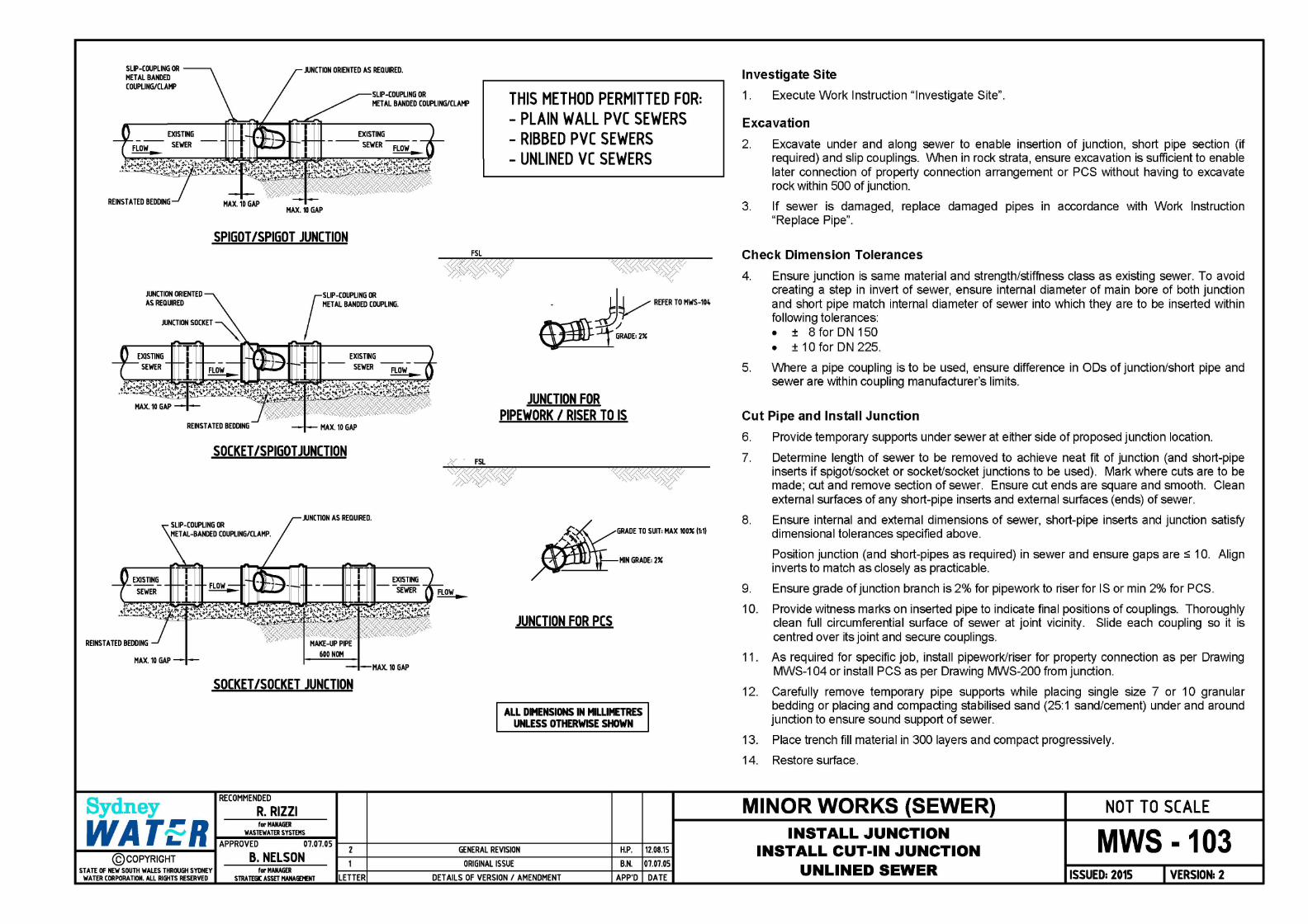
THIS METHOD PERMITTED FOR: - PLAIN WALL PVC SEWERS - UNLINED VC SEWERS
JUNCTION FOR PIPEWORK I RISER TO IS
FSL
~~~GRADE TO SUIT: MAX 100" (1:1)
~HIN GRADE: 2"
/
JUNCTION FOR PCS
ALL DIMENSIONS IN MILLIMETRES UNLESS OTHERWISE SHOWN
WA T .. R for MANAGER ,.,..,,,, WASIDIATER SYSTEMS ... ~A~P~PR-OV~E~D------0~7.0~7-.05""'L~----~~~~~~~~~~~~~~~--------~o-----o
...,_ ________________ ... 2 GENERAL REVISION H.P. 12.08.15
@COPYRIGHT B. NELSON 1 ORIGINAL ISSUE B.N. 07.07.05 STATE OF NEW SOUTH WALES THROUGH SYDNEY
WATER CORPORATION. ALL RIGHTS RESERVED for MANAGER
STRATEGIC ASSET MANAGEMENT LETTER DETAILS OF VERSION I AMENDMENT APP'D DATE
MWS-101
Investigate Site
1. Execute Work Instruction "Investigate Site".
Excavation
2. Excavate under and along sewer to enable placing two halves of junction in position. When in rock strata, ensure excavation is sufficient to enable later connection of property connection arrangement or PCS without having to excavate rock within 500 of junction.
3. If sewer is damaged, replace damaged pipes in accordance with Work Instruction "Replace Pipe", at same time installing cut-in junction in accordance with Drawing W/S-103.
Install Junction
4. At proposed location of connection to PVC sewer or at investigation hole previously cut into VC sewer (refer Work Instruction "Investigate Site"), mark an outline of the elliptical inlet hole to be cut into sewer that matches branch of stainless steel junction. Use a template of branch -do not use the SS junction itself as template.
Do not use permanent markers (e.g. non-water-based markers and paints or spray paints etc) on SS junctions as it may cause corrosion.
5. For PVC sewer, cut elliptical hole in sewer to match elliptical trace of junction branch. Prevent pieces cut from pipe from entering sewer or else retrieve. Use suitable tools to cut the pipe. Do not use hammers and chisels.
For a VC sewer, reshape initial investigation hole to match elliptical trace by cutting, grinding or nibbling edges of hole. Prevent pieces cut from pipe from entering sewer or else retrieve. Ensure edges of hole are smooth and clean. Use suitable tools to cut and grind the pipe. Do not use hammers and chisels.
6. Thoroughly clean full circumferential surface of sewer over length greater than SS junction.
7. Clean and then apply lubricant to corrugated elastomer underlay of junction to ensure it will effectively seal when clamped onto surface of sewer.
8. Place two parts of junction around sewer so branch is aligned with direction of flow and is directly over elliptical opening previously cut in sewer. Look through branch and ensure inlet aligns with and matches size of elliptical hole cut into sewer. As necessary, re-work the cut hole and/or re-align junction before tightening bolts to secure junction in place. Ensure grade of junction branch is 2% for pipework to riser for IS or min 2% for PCS. Re-tighten bolts 10 minutes after initial tightening.
9. As required for specific job, install pipework/riser for property connection as per Drawing MWS-104 or install PCS as per Drawing W/S-200 from junction.
10. Carefully remove temporary pipe supports while placing single size 7 or 10 granular bedding or placing and compacting stabilised sand (25:1 sand/cement) under and around junction to ensure sound support of sewer.
11. Place trench fill material in 300 layers and compact progressively.
12. Restore surface.
MINOR WORKS (SEWER) INSTALL JUNCTION
INSTALL STAINLESS STEEL JUNCTION UNLINED SEWER
NOT TO SCALE
MWS -101 ISSUED: 2015 VERSION: 2

ELLIPTICAL HOLE CUT TO HATCH SS JUNCTION INLET SIZE. LOCATE TO ACHIEVE FALL TO INVERT SPECIFIED FOR EITHER PROPERTY CONNECTION ARRANGEMENT OR PCS CONNECTION
FLOW
FLOW
FLioc._
Sydney
A~
A
EXISTING
SEWER
APPROVED SEALANT APPLIED ALL AROUND CUT TO FILL ANY GAP BETWEEN LINING AND ORIGINAL SEWER PIPE.
EXISTING
SEWER
THIS METHOD MUST BE USED FOR
LINED VC SEWERS
END ELEV A TION A-A
INLET BRANCH PLACED OVER ELIPTICAL HOLE CUT INTO EXISTING SEWER.
BOLTS RE-TIGHTENED BOLTS TEN MINUTES AFTER INITIAL TIGHTENING.
45° JUNCTION LOCATED TO SUIT EXPECTED PROPERTY CONNECTION ARRANGEMENT OR PCS
RECOMMENDED
R. RIZZI
_ ~~ RE~RTOMWS-104
~GRADE:2"
JUNCTION FOR PIPEWORK I RISER TO IS
.""1lE TO Siil• IWI IN• 11-1
HIN GRADE: 2"
/
JUNCTION FOR PCS
ALL DIMENSIONS IN MILLIMETRES UNLESS OTHERWISE SHOWN
WA T .. R for MANAGER
~ ..,_~W-A-STE-~-TE-RS-YS-TEH-S~---11-~--+-~~~~~~~~~~~~~~~~+-~-+-~~ - APPROVED 07.07.05
1----@-co_P_Y-Rl-GH_T __ ... B. NELSON STATE OF NEW SOUTH WALES THROUGH SYDNEY
WATER CORPORATION. ALL RIGHTS RESERVED for MANAGER
STRA TEGC ASSET HANAIEHENT
2
LETTER
GENERAL REVISION H.P. 12.08.15
ORIGINAL ISSUE B.N. 07.07.05
DETAILS OF VERSION I AMENDMENT APP'D DATE
MWS-102
Investigate Site
1. Execute Work Instruction "Investigate Site".
Excavation
2.
3.
Excavate under and along sewer to enable placing two halves of junction in position. When in rock strata, ensure excavation is sufficient to enable later connection of property connection arrangement or PCS without having to excavate rock within 500 of junction.
If sewer is damaged, replace damaged pipes in accordance with Work Instruction "Replace Pipe'', at same time installing cut-in junction in accordance with Drawing MWS-103. If lining is spiral-wound type, first consult Sydney Water.
Install Ju net ion
4. At location of investigation hole previously cut into sewer (refer Work Instruction "Investigate Site"), mark an outline of elliptical inlet hole to be cut into sewer that matches branch of stainless steel junction. Use a template of branch - do not use SS junction itself as template.
Do not use permanent markers (e.g. non-water-based markers and paints or spray paints etc) on SS junctions as it may cause corrosion.
5. Reshape initial investigation hole to match elliptical trace by cutting, grinding or nibbling edges of hole. Prevent pieces cut from pipe from entering sewer or else retrieve. Ensure edges of hole are smooth and clean. Use suitable tools to cut and grind pipe and liner. Do not use hammers and chisels.
6. Thoroughly clean full circumferential surface of sewer over length greater than SS junction.
7. Clean cut face of elliptical hole and apply an approved sealant to completely seal any gap between liner and internal surface of sewer.
8. Clean and then apply lubricant to corrugated elastomer underlay of junction to ensure it will effectively seal when clamped onto surface of sewer.
9. Place two parts of junction around sewer so branch is aligned with direction of flow and is directly over elliptical opening previously cut in sewer. Look through branch and ensure inlet aligns with and matches size of elliptical hole cut into sewer. As necessary, re-work cut hole and/or re-align junction before tightening bolts to secure junction in place. Ensure grade of junction branch is 2% for pipework to riser for IS or min 2% for PCS. Re-tighten bolts 10 minutes after initial tightening.
10. As required for specific job, install pipework/riser for property connection as per Drawing MWS-104 or install PCS as per Drawing MWS-200 from junction.
11. Carefully remove temporary pipe supports while placing single size 7 or 10 granular bedding or placing and compacting stabilised sand (25:1 sand/cement) under and around junction to ensure sound support of sewer.
12. Place trench fill material in 300 layers and compact progressively.
13. Restore surface.
MINOR WORKS (SEWER) INSTALL JUNCTION
INSTALL STAINLESS STEEL JUNCTION LINED VC SEWER
NOT TO SCALE
MWS -102 ISSUED: 2015 VERSION: 2
SLIP-COUPLING OR MET AL BANDED COUPLING/CLAMP
JUNCTION ORIENTED AS REQUIRED.
SLIP-COUPLING OR MET AL BANDED COUPLING/CLAMP THIS METHOD PERMITTED FOR:
- PLAIN WALL PVC SEWERS EXISTING
FLOW-- SEWER ~
JUNCTION ORIENTED AS REQUIRED
EXISTING SEWER
HAX.10 GAP
SPIGOT /SPIGOT JUNCTION
EXISTING
SEWER FLOW -~
MET AL BANDED COUPLING.
(
SLIP-COUPLING DR
T I EXISTING
SEWER
REINSTATED BEDDING HAX.10 GAP
SOCKET /SPIGOT JUNCTION
JUNCTION AS REQUIRED.
EXISTING
SEWER
HAX.10 GAP MAX. 10 GAP
SOCKET /SOCKET JUNCTION
RECOMMENDED
R. RIZZI Sydney
- RIBBED PVC SEWERS - UNLINED VC SEWERS
JUNCTION FOR PIPEWORK I RISER TO IS
GRADE TO SUIT: MAX 100" (1:1)
HIN GRADE: 2"
JUNCTION FOR PCS
ALL DIMENSIONS IN MILLIMETRES UNLESS OTHERWISE SHOWN
WA T .. R for MANAGER
~ .,_~-W-AS-TE-~-TE-RS-YS-TE-HS--~-11---+------------------+----+---1 - APPROVED 07.07.05
~--@-co_P_Y-Rl-GH_T __ ... B. NELSON STATE OF NEW SOUTH WALES THROUGH SYDNEY
WATER CORPORATION. ALL RIGHTS RESERVED for MANAGER
STRA TEGC ASSET HANAIEHENT
2
LETTER
GENERAL REVISION H.P. 12.08.15
ORIGINAL ISSUE B.N. 07.07.05
DETAILS OF VERSION I AMENDMENT APP'D DATE
Investigate Site
1. Execute Work Instruction "Investigate Site".
Excavation
2. Excavate under and along sewer to enable insertion of junction, short pipe section (if required) and slip couplings. When in rock strata, ensure excavation is sufficient to enable later connection of property connection arrangement or PCS without having to excavate rock within 500 of junction.
3. If sewer is damaged, replace damaged pipes in accordance with Work Instruction "Replace Pipe".
Check Dimension Tolerances
4. Ensure junction is same material and strength/stiffness class as existing sewer. To avoid creating a step in invert of sewer, ensure internal diameter of main bore of both junction and short pipe match internal diameter of sewer into which they are to be inserted within following tolerances: • ± 8 for ON 150 • ± 10 for DN 225.
5. Where a pipe coupling is to be used, ensure difference in ODs of junction/short pipe and sewer are within coupling manufacturer's limits.
Cut Pipe and Install Junction
6. Provide temporary supports under sewer at either side of proposed junction location.
7.
8.
9.
Determine length of sewer to be removed to achieve neat fit of junction (and short-pipe inserts if spigot/socket or socket/socket junctions to be used). Mark where cuts are to be made; cut and remove section of sewer. Ensure cut ends are square and smooth. Clean external surfaces of any short-pipe inserts and external surfaces (ends) of sewer.
Ensure internal and external dimensions of sewer, short-pipe inserts and junction satisfy dimensional tolerances specified above.
Position junction (and short-pipes as required) in sewer and ensure gaps are :::: 10. Align inverts to match as closely as practicable.
Ensure grade of junction branch is 2% for pipework to riser for IS or min 2% for PCS.
10. Provide witness marks on inserted pipe to indicate final positions of couplings. Thoroughly clean full circumferential surface of sewer at joint vicinity. Slide each coupling so it is centred over its joint and secure couplings.
11. As required for specific job, install pipework/riser for property connection as per Drawing MWS-104 or install PCS as per Drawing MWS-200 from junction.
12. Carefully remove temporary pipe supports while placing single size 7 or 10 granular bedding or placing and compacting stabilised sand (25:1 sand/cement) under and around junction to ensure sound support of sewer.
13. Place trench fill material in 300 layers and compact progressively.
14. Restore surface.
MINOR WORKS (SEWER) INSTALL JUNCTION
INSTALL CUT-IN JUNCTION UNLINED SEWER
NOT TO SCALE
MWS -103 ISSUED: 2015 VERSION: 2

I I
PRIVAll! PllllPDTY Lii! I ----------------T-----------
TYPICALLY ..
1111 lllAllE 211
Dll•PYC SCJ l'l'E Slllt
: ~1 I I I I I I
DN11t PVC SCJ M 45" PLAll IElll
llMl!il-Jll P\I[ ., 45" SEWER JUNC1DI wmt DNlll SCJ mwlCH
P\IC Im.I SEWER JUNC1DI WITH llN1H SCJ llRAJICll
PVC AEllCIUTllltl SEWOSNI
APPllOX 511-'Jll
TYPICALLY ..
ALL DIMENSIONS IN MILLIMETRES UNLESS OTHERWISE SHOWN
NOTES:-
F FUTlllE PUlllLlli VOMC IY mas, ~ IEECTAIU IWllCRi TAPE IS TU IE TID 10 TIE RISER NI) EXTElll JOO.. IEYOllD SUIFACE LEm.
r-~~~~" . '--~ F FllNIE Pl.UMILlli WGlllC IY 1111ERS.
"' i I
I
I
I A 501115 1600 LOiii HAlllWOCJD PBi IS TO IE PLAaD .al.Y IMR Tiit:
I TRADED ACCESS CAP I I IQ"-'-LDNSEE llSTALLED I llWl.w: PFEWllC I I I t'\11UREHll!Ilal
F!~- -3-.. t!f/::: •· •. ~ :: ... • ·· .•.. · ~ : PLUl•llHIEl&H5TAWll
~---""':'""":-tt-t- .... :· lllAIWif PPEWOllll
t .... EJ ..... ··. llN1M PVC 511.VENI' WEUB AmSS CIUUI& wmt TIIEAllEll Ell>
DNlll PVC SCJ PPE Sl•-BNOTES
DN111 PVC SCJ l'l'E2501.M 11•
SEcr!QNA-A
. . IFllTllEI - Elll1
DNllt P'IC SCJ Flf •llEND
1. THE CD6TROCTOR SHALL INSTAil UP TO AND INCLUDIG 1l£ TIEtDED 1.CCESS CJf IN AU. OOiES.
- - - - - PUMNi LDNSEE llSTALLED lltAIWll! PIPN1IAll MUREi
---- OINSTRUCTlll llSTALLED PIPEW1IAK
2. Al.lERNATIVE RTTINGS MAY BE UTILISED IN 1l£ PCS IN PlJa: OF 1HOSE SHOWN IF APPROYED BY SYll4EY WATER.
J. PROPERIY CONNECJD.I SEWERS AND INSPECTION Slw:TS SHALL BE SURRCllN>ED B'f PFE EMBEl*ENT MATERIAL Y'11H MINNIM 00\'ER OF 150mm TO AU. COIFONENIS. EMBEl*ENT MATERW. stW.l BE SINGL£ SIZE 7 OR 10 CRMUlAR AND stW.l EXTEND 150mm N!DIE. THREMlED ~ rJf.
4. DN100 PROPERTY COttECTION SIZE SHOWN. PIPEWORK AN> RTTING MRANGEMENT MAY BE H>OPTED FOR lARGER OOlttECllONS TO SUT DEYWIPMENT.
5. THE MHMUM LENGTH OF RISER PFE stW.l BE 250mm. DEPIH TO 1IEtDED ACCESS CJf MAY BE LESS~ 1000nvn FOR stW.LOI INSl'AUATIONS TO PRCMDE 1l£ .. NIMIM lOOIH OF RISER PIPE.
6. COht£JION OPTIONS SHOWN ARE FOR AJTURE PUMBING WORK BY OTHERS.
Sydney MINOR WORKS {SEWER) NOT TO SCALE
~~R~-----~----~-~-~-~-~-~-E--R-ro-R-~-0-F-~-~-E-u-~-ffi-o_M_™_E----~DN100P~UP~PE~~NN~TIONMHNGEME~ TECHNICAL SPECIFICATION FOR LEAK TIGHT SEWER H.P. 12.08.15 INSTALL PIPEWORK I RISER
@COPYRIGHT STATE OF NEW SOUTH WALES THAOLGI SYDl£Y
WATER CORPORATION. ALL RHifTS RESERVED LETTER DETAILS OF VERSION I AMENDMENT FOR SINGLE PROPERTY CONNECTION
SYSTEMS {SYDNEY WATER! VERSION 8
APP'D DATE
MWS-104 ISSUED: 2015 VERSION: 1
FSL
45° JUNCTION LAID TO MIN 2% MAX 100% (1:1)
DEPTH TO INVERT
PIPE COVER
Sydney
LU _. al <C LLJ !=::! _. LL. CD LL. <C <C ...... c::-1- LL.
I LL. :z: <C c:> c:: :z: ,_ :z: 2!!: :c :::c ="" '"""" _,...,
45° JUNCTION \ BRAiCH ITYPI
al
>-1-a:
IS
L&.J 1000 NOMINAL ~i----------a: a...•
i
:S DN100 TYP ~ IS
a: <C c :z :::> 0 al
>-1-a: L&.J 1000 NOMINAL ~i----------a: a_ I
i
MAXIMUM 25000 FOR S1 & S2 CONSTRUCTORS MAXIMUM 12000 FOR MS CONSTRUCTORS
NON-DETECT ABLE MARKING TAPE & PEG IF FUTURE PLUMBING WORK BY OTHERS
MARKING TAPE (TYPICAL)
FSL
TRENCH FILL
GEOTEXTILE OVERLAY
NON-DETECT ABLE MARKING TAPE & PEG IF FUTURE PLUMBING WORK BY OTHERS
45° JUNCTION BRANCH (TYP)
x <C ~
c:>C c:> L&.J Ln a: - ffi u..
L&.J a: a.
ALL DIMENSIONS IN MILLIMETRES UNLESS OTHERWISE SHOWN
50 NOMINAL DEPTH POCKET PROVIDED IN BEDDING AT JOINT PRIOR TO LA YING PIPES. VOIDS FILLED DURING COMPLETION OF EMBEDMENT.
TRENCH DETAILS PIPE JOINT BEDDING POCKETS
RECOMMENDED
R. RIZZI
WA T .. R for MANAGER
~ .,_~-W-AS-TE•WA-TE-RS-YS-TE-HS--~-11----+-------------------+---+----1 - APPROVED 07.07.05 2 GENERAL REVISION H.P. 12. 08.15 ..,_ __ @_CO_P_Y-Rl-GH_T __ ... B. NELSON
STATE OF NEW SOUTH WALES THROUGH SYDNEY WATER CORPORATION. ALL RIGHTS RESERVED
for MANAGER STRA TEGC ASSET HANAIEl'ENT LETTER
ORIGINAL ISSUE B.N. 07.07.0
DETAILS OF VERSION I AMENDMENT APP'D DATE
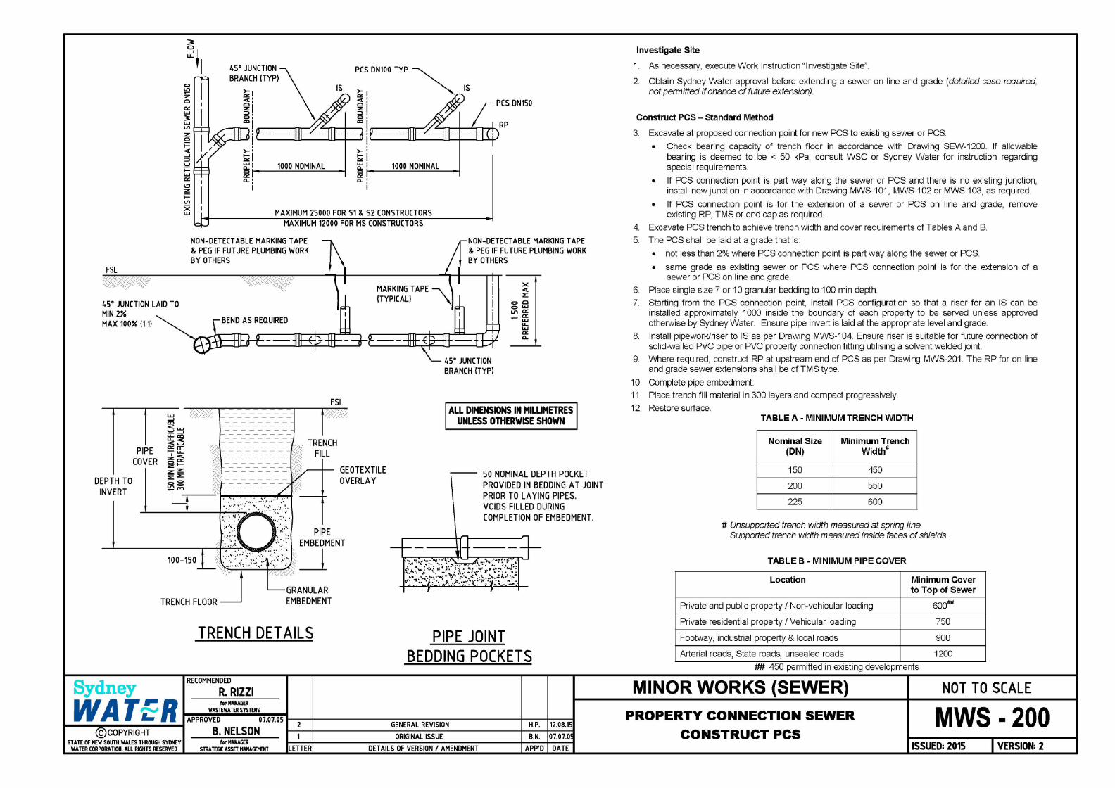
Investigate Site
1. As necessary, execute Work Instruction "Investigate Site".
2. Obtain Sydney Water approval before extending a sewer on line and grade (detailed case required, not permitted if chance of future extension).
Construct PCS - standard Method
3. Excavate at proposed connection point for new PCS to existing sewer or PCS.
• Check bearing capacity of trench floor in accordance with Drawing SEW-1200. If allowable bearing is deemed to be < 50 kPa, consult WSC or Sydney Water for instruction regarding special requirements.
• If PCS connection point is part way along the sewer or PCS and there is no existing junction, install new Junction in accordance with Drawing MWS-101, MWS-102 or MWS 103, as required.
• If PCS connection point is for the extension of a sewer or PCS on line and grade, remove existing RP, TMS or end cap as required.
4. Excavate PCS trench to achieve trench width and cover requirements of Tables A and B.
5. The PCS shall be laid at a grade that is:
• not less than 2% where PCS connection point is part way along the sewer or PCS.
• same grade as existing sewer or PCS where PCS connection point is for the extension of a sewer or PCS on line and grade
6 Place single size 7 or 10 granular bedding to 1 DO min depth
7. Starting from the PCS connection point, install PCS configuration so that a riser for an IS can be installed approximately 1 ODO inside the boundary of each property to be served unless approved otherwise by Sydney Water. Ensure pipe invert is laid at the appropriate level and grade.
8. lnstal I pipework/riser to IS as per Drawing MWS-104. Ensure riser is suitable for future connection of solid-walled PVC pipe or PVC property connection fitting utilising a solvent welded joint.
9 Where required, construct RP at upstream end of PCS as per Drawing MWS-201 The RP for on line and grade sewer extensions shall be of TMS type.
10. Complete pipe embedment.
11. Place trench fill material in 300 layers and compact progressively.
12. Restore surface. TABLE A - MINIMUM TRENCH WIDTH
Nominal Size Minimum Trench (ON) Width#
150 450
200 550
225 600
# Unsupported trench width measured at spring line. Supported trench width measured inside faces of shields.
TABLE B - MINIMUM PIPE COVER
Location Minimum Cover to Top of Sewer
Private and public property I Non-vehicular loading 600##
Private residential property I Vehicular loading 750
Footway, industrial property & local roads 900
Arterial roads, State roads, unsealed roads 1200
t#f. 450 permitted 1n ex1st1ng developments
MINOR WORKS (SEWER) NOT TO SCALE
PROPERTY CONNECTION SEWER
CONSTRUCT PCS MWS -200
ISSUED: 2015 VERSION: 2

INSPECTION COVER
FSL FSL General
Use either a site-assembled rodding shaft or prefabricated terminal maintenance shaft (TMS) to provide maintenance access to a PCS. If an existing sewer is being extended, a prefabricated TMS shall be installed.
I"'"'+----DN 150 RISER Procedure
RUBBER RING JOINTS--.........
EMBEDMENT SINGLE SIZE 7 OR 10
2% GRADE ON JUNCTION BRANCH
DN 375 PVC PIPE SHROUD 300 LONG
o..n N
+I C>
~
150 MINIMUM ----~J..Y....i EMBEDMENT MATERIAL
EMBEDMENT
Sydney RECOMMENDED
R. RIZZI
ELEVATION
2x45" BENDS (RRJ) OR 1x90" LONG RADIUS BEND (RRJ). (SEE NOTE 1)
RODDING SHAFT
INSPECTION COVER FILL GRADED TO FSL (1:4 MAX)
25
C> o..n +I
C> C> N
DN 225 RISER
2% GRADE ON JUNCTION BRANCH
FRAME, COVER & SURROUND. (NON-TRAFFICABLE SHOWN)~
FSL
o..n N
+I
END ELEV A TION
TERMINAL MAINTENANCE SHAFT
,-...,,; WASTEWATER SYSTEMS WA T .. R for MANAGER
~ ~A-P~P-RO-V~E~D-------0~7-.0~7.~05-:-----t--------------------+--+----ll ..,_ ________ ....,,,. B NELSON 2 GENERAL REVISION H.P. 12.08.15
@COPYRIGHT ' ORIGINAL ISSUE B.N. 07.07.0 ST ATE OF NEW SOUTH WALES THROUGH SYDNEY for MANAGER
WATER CORPORATION. ALL RIGHTS RESERVED STRATEGIC ASSET HANAGEl£NT LETTER DETAILS OF VERSION I AMENDMENT APP'D DATE
(SEE NOTE 5)
~-- INSPECTION COVER
1. For rodding shaft option, connect 2 x 45 degree bends (or 1 x 90 degree) to terminal junction. Bends and riser to be same size as PCS.
2.
3.
4.
5.
6.
7.
OR For TMS option, connect base piece of TMS to terminal junction.
Place single size 7 or 10 granular bedding under bend or base piece.
Orient rising bend or base piece to ensure riser will be vertical.
Place bedding over and around bend or base piece.
Connect riser pipe ensuring it is vertical.
Place bedding around riser. Ensure bedding material will support cover and surround without settlement.
Trim riser as required to achieve specified clearances from inspection cover.
8. Fit inspection cover to riser; fit frame, cover and surround. If DN 225 riser, use arrangement shown for TMS.
9. Place, grade and compact fill material around the cover and surround.
FILL GRADED TO FSL (1:4 MAX)
FSL ALL DIMENSIONS IN MILLIMETRES
UNLESS OTHERWISE SHOWN
MINOR WORKS (SEWER)
PROPERTY CONNECTION SEWER
CONSTRUCT RODDING POINT
NOT TO SCALE
MWS · 201 ISSUED: 2015 VERSION: 2
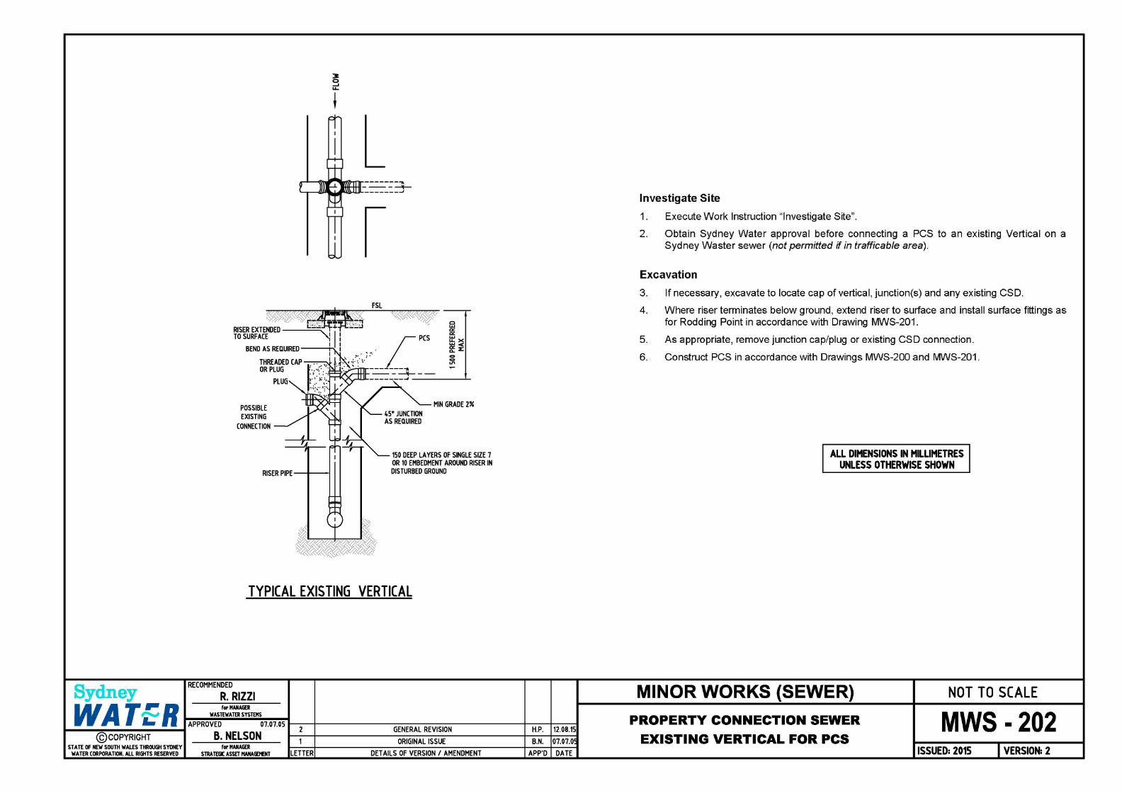
Sydney
POSSIBLE EXISTING
CONNECTION
RISER PIPE-+---i
FSL
c .... c:: c:: .... u.x .... < g: z: 0 0
"' -
MIN GRADE 2%
150 DEEP LAYERS OF SINGLE SIZE 7 OR 10 EMBEDMENT AROUND RISER IN DISTURBED GROUND
TYPICAL EXISTING VERTICAL
RECOMMENDED
R. RIZZI
WA T .. R for MANAGER
~ .,_~-WA-ST-EW-M-ER-SY-~-EH-S~--11-~--+~~~~~~~~~~~~~~~~---1~~1-----1 - APPROVED 07.07.05
..,_ __ @-co_P_Y-Rl-GH_T __ ... B. NELSON STATE OF NEW SOUTH WALES THROUGH SYDNEY
WATER CORPORATION. ALL RIGHTS RESERVED for MANAGER
STRA TEGC ASSET HANAIEl'ENT
2
LETTER
GENERAL REVISION H.P. 12. 08.15
ORIGINAL ISSUE B.N. 07.07.0
DETAILS OF VERSION I AMENDMENT APP'D DATE
Investigate Site
1. Execute Work Instruction "Investigate Site".
2. Obtain Sydney Water approval before connecting a PCS to an existing Vertical on a Sydney Waster sewer (not permitted if in trafficable area).
Excavation
3.
4.
5.
6.
If necessary, excavate to locate cap of vertical, junction(s) and any existing CSD.
Where riser terminates below ground, extend riser to surface and install surface fittings as for Rodding Point in accordance with Drawing MWS-201.
As appropriate, remove junction cap/plug or existing CSD connection .
Construct PCS in accordance with Drawings MWS-200 and MWS-201.
ALL DIMENSIONS IN MILLIMETRES UNLESS OTHERWISE SHOWN
MINOR WORKS (SEWER) NOT TO SCALE
PROPERTY CONNECTION SEWER
EXISTING VERTICAL FOR PCS MWS -202
ISSUED: 2015 VERSION: 2

GEO TEXTILE FILTER
FABRIC FOR ALTERNATIVE
150 MIN -'---;~--.-:::om...:..
FSL
PIPE EMBEDMENT
DN 100 TRENCH DRAINAGE (ALTERNATIVE LOCATION)
~.J4.---r~ DN 100
Investigate Site
1. Execute Work Instruction "Investigate Site".
Excavation
PIPE EXTENSION
2.
3.
4.
5.
JOINT SEALED WITH TAPE TO 6·
PREVENT CONCRETE ENTERING PIPE JOINT
7.
Excavate and expose full length of sewer to be encased.
Determine if any live and/or disused junctions are within length to be encased.
Do not encase existing junctions without prior Sydney Water approval.
Check bearing capacity of trench floor in accordance with Drawing SEW-1200. If allowable bearing is deemed to be <50 kPa, consult WSC or Sydney Water for instruction.
If sewer is damaged, either as a result of excavation or other causes, consult WSC or Sydney Water for instruction.
Complete excavation under sewer, supporting each excavated pipe on precast concrete support blocks or hessian bags filled with stabilised sand (25:1 sand/cement) placed at 3 m spacing or one under each pipe, whichever is lesser distance.
CONCRETE
TRENCH DRAINAGE (PREFERRED LOCATION)
JUNCTION IN ENCASED SECTION 8.
Replace mortar-jointed VC, Cl & DI pipes, defective pipes and other pipes as directed by WSC or Sydney Water and in accordance with Work Instruction "Replace Pipe".
Unless otherwise authorised, remove junctions and reinstate sewer in accordance with Work Instruction "Replace Pipe". 200 MIN
UN-REINFORCED CONCRETE ENCASEMENT
12 THICK COMPRESSIBLE AND DURABLE MEMBRANE PROVIDED AT EACH RUBBER RING JOINT (UNLESS IN ROCK). PIPE JOINT SEALED WITH TAPE TO PREVENT CONCRETE ENTERING PIPE JOINT.
600 I MINIMUM TWO DOWEL PINS, EACH LOCATED CENTRALLY WITHIN CONCRETE ENCASEMENT. EACH DOWEL SHALL BE LOCATED ON OPPOSITE SIDES OF THE PIPE (SEE DETAIL Al
ROCKER PIPE H600
1--------------.-.......,...,.......-t-,..,.......----,,--------; IF PIPES REPLACED
HESSIAN BAG FILLED WITH STABILISED SAND (10:1 SAND/CEMENT)
DOWEL PIN
DETAIL A
9. Arrange for WSC or Sydney Water inspection of sewer before concrete encasement.
Pipework Preparation
10 Ensure sewer and trench are free of debris and loose spoil.
11. Where Sydney Water has authorised a junction to remain or to be located in encased sewer, connect a length of pipe to junction. Extend pipe so that its socket (or, alternatively, a coupling at spigot end of a pipe) is located at proposed edge of encasement. Cap extended socket/coupling and wrap in polyethylene prior to placing concrete.
12. Install rocker pipes (if pipes replaced).
13 Place compressible membrane and steel dowels at all encased flexible joints (not required for SCJs).
14. Install support/restraint system to prevent pipe movement/floatation during concrete placement.
15. Install drainage pipe, ensuring both upstream and downstream ends of pipe protrude past concrete encasement into granular embedment. Wrap ends of drainage pipe in geotextile fabric. Where encasement ends within 1000 of a MH, extend encasement to MH. Extend drainage pipe beyond MH to adjoining pipework embedment.
Encasement
16. Use normal class concrete to AS 1379, and min strength Grade 20. Whilst progressively withdrawing pipe supports, place concrete along one side of sewer and vibrate concrete so it flows under sewer to height of haunch on other side.
17. Do not let free fall of concrete exceed 1.6 m and do not permit concrete to impact directly on exposed sewer.
•-----=~ PIPE STRAPS OVER SEWER AND PEGGED TO TRENCH FLOOR. MINIMUM 400 LONG MET AL PEGS AT 2000 SPACING (OR EQUIVALENT ALTERNATIVE RESTRAINT!.
SPIGOT /SOCKET JOINT OR SLEEVED COUPLING ALL DIMENSIONS IN MILLIMETRES
UNLESS OTHERWISE SHOWN
18. Continue to place concrete around sewer from both sides to achieve specified cover. Stop concrete 10 short of face of pipe socket each end. Vibrate concrete.
19. Make work site safe during initial curing period and allow min 24 hours curing before placing and compacting trench fill.
20. Remove any temporary forms without disturbing concrete.
21. Place trench fill material in 300 layers and compact progressively.
22. Restore surface. RECOMMENDED
R. RIZZI Sydney MINOR WORKS (SEWER) NOT TO SCALE
WA T .. R forHANAlER ,.,.,,,,, WASTEWATER SYSTEMS ~ ~A-P-P-RO•V•E•D---.-.---0-7-.0-7.-0S"t-~---1~~~~~~~~~~~~~~~~~~-+~~+--~~
~-----------11 B NEL N 2 GENERAL REVISION H.P. 12.08.15 @COPYRIGHT • SO ORIGINAL ISSUE B.N. 07.07.0
MWS · 300 CONCRETE ENCASE SEWER STATE OF NEW SOUTH WALES THROUGH SYDNEY for HANAIER
WATER CORPORATION. ALL RIGHTS RESERVED STRATEGIC ASSET MANAGEMENT LETTER DETAILS OF VERSION I AMENDMENT APP'D DATE ISSUED: 2015 VERSION: 2

Sydney
10 MAX GAP
r NEW PIPE
STAINLESS STEEL CLAMP CENTRED DN JOINT
STAINLESS STEEL REPAIR CLAMP METHOD
NEW PIPE MET AL-BANDED CLAMP CENTRED ON JOINT
METAL-BANDED FLEXIBLE COUPLING METHOD
BOTH SIDES OF PIPE WELL LUBRICATED
SOUND EXISTING
PIPE
10 MAX. GAP COUPLING SLIPPED ALONG MAKEUP PIPE TO CLEAR END AND SLIPPED BACK ONCE COUPLING IN POSITION.
LUBRICATED RUBBER RING
SLIP-COUPLING METHOD PLAIN WALL PIPE
COUPLING SLIPPED ALONG MAKEUP
SOUND --EXISTING
PIPE
PIPE TO CLEAR END AND SLIPPED REINSTATED BEDDING BACK ONCE COUPLING IN POSITION.
SLIP-COUPLING METHOD PROFILED WALL
RECOMMENDED
R. RIZZI
ALL DIMENSIONS IN MILLIMETRES UNLESS OTHERWISE SHOWN
WA T .. R for MANAGER ,...__, WASTEWATER SYSTEMS ~ ~A~P~P~RO-V~E_D _______ 0~7-.07~.o~s"'t---t--------------------+---+----..... ________ .....,. B NEL N 2 GENERAL REVISION H.P. 12.08.15
@COPYRIGHT ' SQ 1 ORIGINAL ISSUE B.N. 07.07.0 STATE OF NEW SOUTH WALES THROUGH SYDNEY for MANAGER
WATER CORPORATION. ALL RIGHTS RESERVED STRATEGUSSET MANAGEMENT LETTER DETAILS OF VERSION I AMENDMENT APP'D DATE
Investigate Site
1. As necessary, execute Work Instruction "Investigate Site".
Excavate and Support Existing Sewer
2. Excavate and expose full length of sewer to be replaced. Achieve min 100 clearance between underside of sewer and trench floor. Support each excavated pipe. At each end of section to be removed, place supports under exposed section of existing sewer not being removed i.e. immediately adjacent to intended cut locations.
3. Ensure proposed cuts are at least 400 from a remaining socket. Cut and remove pipes to be replaced. Clean remaining pipe ends and ensure cut faces are square.
4. Prepare trench floor e.g. remove or trim rock outcrops and treat soft or loose areas. Check bearing capacity of trench floor in accordance with Drawing SEW-1200. If allowable bearing is deemed to be <50 kPa, consult WSC or Sydney Water for instruction regarding special requirements.
5. Compact fill and disturbed areas. Remove debris and water before placing bedding.
For Unlined Sewers
6. Ensure replacement pipes are same material and strength/stiffness class as existing sewer. Exceptions are where VC, Cl & DI pipe can be replaced by PVC pipe as part of concrete encasement work. Ensure that internal diameters of existing sewer and replacement pipes match within the following tolerances: • ± 8 for ON 150 • ± 10 for ON 225.
7. Where a coupling is to be used, ensure difference in ODs of replacement pipe and sewer are within coupling manufacturer's limits.
Note: Consult Sydney Water for instruction if replacement pipes do not meet material, stiffness, strength and/or dimensional requirements e.g. lip of sewer may need to be ground (tapered) or a maintenance structure be constructed at upstream face of encasement, or pipes may need to be replaced from MH to MH.
For Lined Sewers
6.
7.
Completely fill any gap between the sewer and its liner using an approved epoxy mastic. Measure and record any difference in internal diameters of lined pipe and replacement pipe
Where a difference exists in internal diameters, file or grind end of appropriate pipes (at least 3 o'clock to 9 o'clock) to approximately 30 degrees to achieve smooth transition. Use suitable tools to cut and/or grind the pipe/liner. Do not use hammers and chisels.
8. Set replacement pipes to line and grade, ensuring gaps between existing sewer and replacement pipes are :::;; 10.
9. Thoroughly clean surfaces of pipes before installing clamps or couplings. Connect pipes by means of flexible couplings centred over each joint.
10. Unless pipes to be concrete encased (refer Drawing MWS-300), complete pipe embedment.
11. Place trench fill material in 300 layers and compact progressively.
12.
13.
Restore surface.
For lined sewers, advise Sydney Water in writing of: • type of lining found • location, length, material and stiffness of replacement pipes inserted into sewer • difference in internal diameters of lined sewer and replacement pipes.
MINOR WORKS (SEWER) NOT TO SCALE
REPLACE PIPE MWS -400 ISSUED: 2015 VERSION: 2