technical spocificntion - cern · technical spocificntion si/int. ti/i.ae/ 68-l~ ... conductor...
TRANSCRIPT

' .
Technical Spocificntion
SI/Int. TI/I.AE/ 6 8-L~ 10.6.1968
SPECIFICATION J:"OR 10 CM-BORE QUADRUPOLE BEAM rrRANSPORT
MAGNETS l!'Oll THE CERN MPS-DIVISION
P. Bossard
PS/6605

- 2 -
TABLE OF CONTENTS
1. INTRODUCTION
1.1. Gonoro.l • . . . . • • • • • 1.2. Typos of Quo.drupolos; Mo.in Po.rnnotors • • • • • 1.3. Scope of tho Tonder • • • • . 1.4. Access to Inforr.mtion nnd •.rests • • • • • 1.5. Guo.ran too • • • • • 1. 6. Delivery . • .
2. Ml\.GNETIC CIRCUIT
2.1. Mccho.nicnl Construction • • • • • 2.2. Magnetic Properties of tho Stool . . .
3. EXC ITATION COILS
3.1. General • • • • • 3.2. Conductor Material nnd Dinonsions • • • • •
Construction and Insulation of tho Coils. • • • • 3.4. Cooling o.nd Thornal Protection
3.5. Leak and Flow Tests
3.6. Eloctrico.l Tests
• • • • •
• • • • •
• • • • •
PAGE
4
L'r
5
5
5
5
6-7-8 8
9
9-10
10-11-12
12-13-14
1'1r-l 5
15-16-17
3.7. Mounting and Mochnnicnl Protection of tho Coil. • 17
4. MISCELLANOUS
PS/6605
4.1. Marking Flo.to
4.2. Tochnico.1 Inforno.tion to bo furnished
4.3. List of So.nplos to be furnished
4.4. Transport
4.5. List of CERN Standard Accessories
• • • • • • • • • • • • • • • . . . . .
17
18-19
19
19-20

PS/6605
- 3 -
LIST OF SFECH'ICATION DRAWINGS
1) Gonora l Assembly
Typo A
2) Core
Typo A
3) Coil
Typo A
4) Roforence Support
5) Interlock Circuits
28-3381-0
28-3382-0
28-3383-0
28-1862-3
28-3387-3

- .. i -
1. INTRODUCTION
1.1. Genera.l
In order to extend tho oxperiaontnl facilities of tho 28 GoV -
CERN - Proton - Synchrotron,and to increase tho nunbor of experiaontal
beans, a further nunbor of quadrupole nagnots is required.
The quadrupole nagnots described in this specification shall
produce nagnetic fields with a uniforn gradient for the focusing of
beans of charged particles. Since the nagnots will be suppliod with
direct current, their no.gnetic circuits can be nado of solid stool blocks.
1. 2. Types of Quo.drupolos i Main Pnranctors
(see Gonernl assonbly drawing)
In tho final stage, thoro will bo different sizes of quadrupolcs
figuring as typos A, B etc., having tho sane cross-section of the core
and the coils, but different lengths. As they arc natched for oquo.l coi1
resistance, they present different nunbors of turns and different
profiles of copper conductors. Their nain paranoters are given in the
following table.
The no.in drawings, as listed on Pago 3, arc attached at the end of
the specification.
ML\.IN PARAMETERS
Type A B c Aperture 10 ~ ( en)
Iron Length 120 (en )
Non. gradient 2000 (G/cn)
Non. current 540 (A )
Resistance at 20°0 0.19 (Ohn)
Nor.:. Power 60 (kW )
Max. Toop. rise 40 ( oc )
Water flow rate 24 (l/nin)
Pressure drop ~10 ( o.tn)
Nw:iber of turns tlrl per polo
Approx weight 2.5 (ton)

PS/6605
- 5 -
1.3. Scope of the Tonder
It is understood tha,t tho contr8.ctor shall mo.nufo.cturo, test and
dulivor to CERN, Moyrin, tho quadrupole magnets completely assembled
according to tho present specification. All equipment for monitoring
tho temperature and flovv of tho cooling water, tho protective covers
etc., must be supplied ond mounted by tho mo.nufacturor, so tho.t after
delivery tho magnets arc ready for immediate service.
Tenders do not include tho m::i.i1ufn.cturo of o.ny pnrt of the
supporting base, which will bo ordorod scpo.ro.tely by CERN.
1. 4. Access to Informo.tion and Tests
It is demanded that CERN be informed about all technical details
of tho construction o.nd of any subcontracting. Tho contractor must
supply throe complete sots of fabrication drawings, for internal use
at CERN,
CEilN also demands tho right of access to the factory during tho
fabrication nnd to have a roprosento.tivc present o.t all tests described
in this specification.
1. 5 Guarantee
Tho attached drawings arc tho result of an initial study. Tho
manufacturer is entirely responsible for his design and must guo.ro.ntoo
for o. fo.ultloss construction of tho mngnot.
Ono yoo.r after acceptance, o.11 aho.racteristics must still moot
the present specification.
Tho formal nccepto.nco of tho magnets will be postponed until they
have boon excited to full magnetic field and their po.rnmotors measured
o.t CERN. This testing shnll take plo.co within throe months o.ftor
delivery of the complete order.
1. 6. Deli very
CERN is interested in o. short delivery time, such o.s 8 ••• 10
months for tho first mo.gnat, after tho date of order.

PS/6605
- 6 -
2. MAGNETIC CIRCUIT
2 .1. Moclmic o.l Construction ( see drawing of the core)
Tho mo.gnotic circuit is composod of four polo blocks, whoroo.t
co.ch upper o.nd lowor po.ir forms ono sopo.rntc magnetic flux po.th. Tho
different po.rts nro kept together with countersink bolts o.nd positioned
by monns of side plo.tos o.nd pins, so tho.t tho quo.drupolos co.n be
o.ssomblod with tho required stability o.nd precision, in o. reproducible
way, and to olimino.to doformo.tions of tho go.p due to mo.gnotic forces.
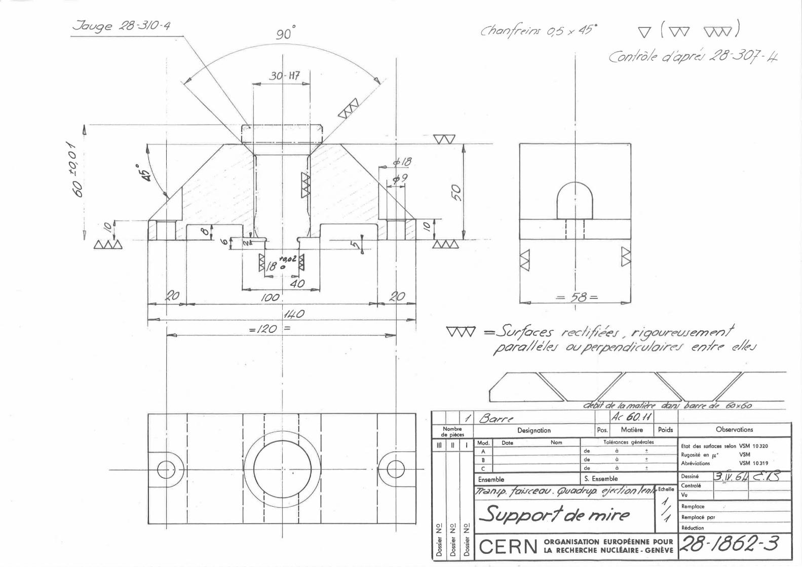
For lntor alignment purposes, neo.r each end, on top of tho magnet,
a high precision roforonco support must be mounted, which will bo
delivered by CERN. (soc drawing o.tto.chod)
To obto.in tho required uniformity of tho magnetic field gradient,
tho following tolerances must be strictly adhered to, in addition to
those given on tho drawings.
Tolerances
a) The polo-faces, comprised between P o.nd n, must be finished with a
surface quality of o.bout 1.6 µ, (R = 1.6 #o, according to ISO
Sto.ndo.rds).
b) The pole profiles, comprised between P o.nd R, must coincide with
tho indico.tod contour within~ 0.05 mm.
c) Longitudinally, corresponding points of tho profile must lie on
straight ·linoo within + 0.05 mm.
d) The end surfaces of the poles must be perpendicular to tho
longitudinnl centre plo.no to.:!::. 0.3°.
o) After assemblage, tho two dinmoters between opposite polo tips
must be 100 + O.l mm, and everywhere along-tho axis they must not
differ from co.ch other by more thnn O.l mm.
f) After o.ssomblo.gc, at any tro.nsvorso.l cross-section, tho position
of tho four polo faces relative to co.ch other, i.e. the aperture

PS/6605
- 7 -
symmetry, must bo nccurato to± 0.05 ma or± 0.02°, whichGvor is
smaller. Therefore, for co.ch single polG block, tho position
(nnglcs o.nd dista.noos) of tho polo profile rolo.tivo to tho outer
surfo.ccs towo.rds tho magnetic circuit, o.nd tho precision of.tho
side plntos, must be verified o.ccordingly before nssomblo.go.
g) Loco.l o.ir go.ps, if m1y, botwoon tho different joints of pole blocks
ond side plntcs must not exceed 0.05 mm.
h) After o.ssomblo.gc, the four distances between tho edges P nnd R of
ndjncont polos must bo equnl within 0.05 rrun, ncnr ca.ch end of a.
quo.drupolo. A compa.rntor or micrometer must bo employed, ho.ving
specially shnpod o.nvils for these moasuraments.
i) Tho reference supports must be positioned with tho following
accuracy:
Their bo.sos must bo pnrallol to tho horizontal symmetry pla.no
within 0.01 mm, nnd o.t tho ratod distance to + 0.02 mm.
Tho contra lines of their bores must cross within + 0.02 mm of
tho mo.gnat contra line.
Tho lon&itudinnl distance from one support to the other,
monsurod between their boro centre lines, must bo within
+ O.l mm.
Inspection
Before o.ssomblo.go, all po.rts of tho magnetic circuit will bo
inspected by a roprosonto.tivo of CERN, ond the gap dimensions chocked
after tho mngnot hns boon nssomblcd without coils. About suitable
methods nnd mcnsuring equipment shall be discussed later, but in
principle tho mnnufncturor must supply tho instruments ns tomplo.tos,
micrometers, optico.l devices etc., required for this oxnmination.
Moreover it must bo proved tha.t tho assembly cnn be mo.do in a.
reproducible wo.y, so that the dimensions of tho finished qundrupolos

- 8 -
nro tho samo ns domonstrntod without coils.
Finish
Except for tho gap surfaces, which must be protected by an agreed
rust provontntive only, tho whole mngnot must be painted with nt least
one coat of priming and two finishing coats of an ono.mel to bo soloctod
in agroomont with CERN.
2.2. Mngnetic Properties of t h o Stool
Tho magnetic circuit must be made of annealed low cnrbon stool,
forged or laminated, having for example tho following composition:
0.05 o/o C
0.02 o/o P
O.l o/o Si
0.02 o/o S
O.l o/o Mn
Cr. Ni trncos
Tho coercive force of tho stool must be smallor thnn 2 A/cm, and
tho flux density for an excitation of 300 A/cm nust oxcood 20 400 Gauss.
Tho manufacturer must supply nt least one sample of onch stool
butch of which tho magnets will bo made. To conform to our existing
npparntus, tho sa.mplos must be properly machined rings having an
inner diruneter of 76 .±. 0.1 mn, outer dionotcr of 114 + 0.1 nm nnd n
width of 15 + 0.1 nm.
Tho samples will be measured at CERN nnd must satisfy tho
specification as detailed nbovo. CERN reserves tho right to reject
magnets presenting inhomogeneities of tho mngnetic field, caused 'by
defects in tho iron body (roforonco is made to section 1.5 nbout iho
formal ncceptnnco).
In tho event of irresolvable disputes concerning tho results of
magnetic moasuromonts, a neutral institution will bo asked to arbitrate.

PS/6605
- 9 -
3. EXCITATION COILS
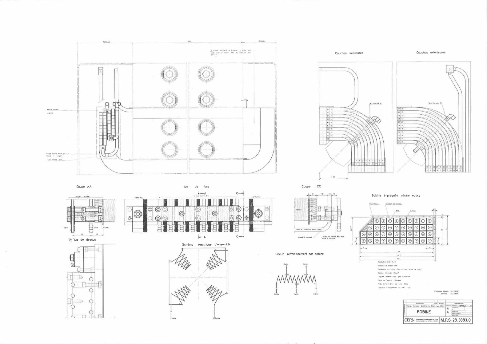
3.1. Genero.l (sec dro.wing of the coil)
The winding is composed of four singlo pole coils, which nre
fixed .to the yoke by ne0,ns of clo.mps.
Temporo.ture gro.dionts due to wo.tor cooling and magnetic forces
subject the coils to honvy mechanical stresses.
The mnnufo.cturor nust o.ssumo complete responsibility tho.t the
coils will sntisfy o.11 roquirenonts for tho tests described horonfter,
and o.ssuro undisturbed safe operation la.sting for yea.rs.
3.2. Conductor Mo.tcrio.l ond Dinensions
The conductors must be made . of electrolytic copper having a -8 0 resistivity inferior to 1.76 • 10 Ohl~.m at 20 c. Preference should
be given to the so-called OHFC-type, freo from go.s, which co.n bo
brazed without difficulty.
'Tho cross-section of the conductors is o. roctnngle with slightly
rounded corners and o. contro.l cooling duct. It l'J.ust have tho follqwing
dimensions:
Outer dimensions
Rounded of with r =
Dinm. of cooling duct
Min. copper c.s. o.ren
Min. cooling c.s. o.reo.
8.0
A
x 8.0
1
4.5
46
15
I B I c I
Although tho shape of tho conductor no.y be slightly different,
the above minil'J.uo cross-soctiono.l o.roo.s muot be mo.into.inod.
2 mm
nn
nm 2
mm 2 mn

PS/6605
- 10 -
ThG manufacturer must guarantee that the resistance of the
finished magnets docs pot oxceGd 0.19 Ohm, at room temperature.
All brazings must be carried out with great care. No joints
between conductors inside of a layer are admitted. All joints,
inside and outside thG coils, must be absolutely watertight and not
increase appreciably tho electrical resistance. The manufacturer
is entirely responsible that no.obstruction nor leakage may over
years of magnet operation occur.
The manufacturer must submit a few samples of tho copper and of
all particular sorts of brazing connections to be employed.
3.3. Construction and insulation of the coils
The coils consist of completely mou1ded blocks. The coil sides
aro placed under 90° into the cross-like air gap. Tho coil end
connections must bo bent outwards sufficiently, so as not to reduce
the width of the gap aperture. All coils are electrically connected
in series.
The coils arc cooled by four parallel water circuits (i.e. one
layer per circuit) for type A quadrupoles.
ln..gene.ra:;L, tP.E:1 inlet tcmpe)'.'ature of the cooling water will be
above tho dewpoint of tho surrounding atmosphere, but occasionally
it may be as low as 10° c, so that the coils can be completely
saturated with water condensed from the atmosphere. It is therefore
important, that the insulation be guaranteed watertight, to avoid
short circuits under these circumstances.

- 11 -
Tho mo.xinum temporaturo riso of the cooling wntor being a.s high
ns 50° c, tho difference of thormnl oxpunsion between o.djo.cont
conductors would ,'IBJ.ount to 1 ••• 2 mi~, if thoy could movo frooly. Tho
coil must bo constructed in such n way nnd tho insulntion must be
sufficiently strong o.nd cletstic, tho.t oven n lo.rgc nunbor of thorrrml
cycles will not co.use cro.clrn in tho insulo.tion.
Tho insulo.tion for the individuo.l conductors o.nd the mo.ss
insulo.tion for the pole coils nust be built up with to.pas consisting
of glo.ss o.nd integro.ted nico... No othor mo.teric..ls (i. c. cotton, nico.
foils, etc.) o.re o.dmitted. The to.pas nust be of tho typo specially
treated in order to obtnin a good ndhosion to epoxy resins. For the
so.me reason the conductor must be co.refully cloo.nod with acetone or o.
similar solvent irmodio.tely before tho insulating process.
All pnrts of the coil must be inprognatod under vo.cuui~1. Tho
choice of tho epoxy rosin mid details of the inpregnation procedure
aro tho responsibility of tho nnnufncturor. In principle, it is also
perl'.li ttod to omploy opoxy pro-i:r:1pregnated tapos, which do not
necessarily imply a further vo.cuun treo.tnont, but o.doquato rnoo.suros
must bo undertaken to obtain o. quo.lity o.s high as by proper vacuun
inpregno.tion.
Before the construction of tho coils co.n be stnrtod, the
mo.nufacturcr must subni t CL few sn.:r:1ples of the insulation to be
employod, mo.de on conductors of conparo.blo sizo. After tho.t, o. proto
type coil rmst bo no.de, which shnll be subjected to an o.ccelero.tod
o.geing test (thermal cycling). It is undorstood tho.t this prototype
coil is not used for tho no.gnats n.ftorwo.rds.
Therno.l cycling of tho prototype coil nust be perforncd na
follows:
Tho coil is supplied n.t nonino.l current nnd so:newho.t reduced ro.to of
cooling water. A tenporo.ture nonitor, plncod on tho wn.ter outlet,
reo.cts when o. pro-selected tel'.lporo.ture is roo.ched, reversing the

- 12 -
direction of water flow and intcrruptinG tho current. After n certo.in
dclo.y the current is reset, until the so.mo temperature rise -occurs in
the opposite wo.y; tho tomporo.ture noni tor reacts o.gain, etc. After
every 200 revorenls (i.e. 100 complete inverted cycles) with succeeding
tenpero.turc rises of 0 T = l0°c, 20°0, 30°c, 40°0 and 50°0, tho coil
insulation must be tested as given under 3.6. b) and 3.6. c) (electrical
tests).
Tho prototype coil will be considered satisfactory, when after
the 500 thermal cycles it still withstands tho olectrico.l tests and
shows no shearing of tho conductors. If the prototype coil is a
failure, tho mnnufo.cturer must improve its design o.nd construct n new
prototype, until o. so.tisfa.ctory solution has been found •. Only after
this can the serio.l production of tho rno.gnets be startocl.
The connections between the coils nro mo.de with copper bars,
adequately insulated fron the yoke. To conform to the existing cnbles,
the main terminals must bo made exo.ctly o.s indicated on the drawings.
3. 4. Cooling and thermo.l J;lrotection
Epoxy- or rubber insulated copper tubes, lend out to the main
water manifolds, which must be mo.de of copper or sto.inloss stool. Tho
copper tubes a.re insulated from the manifolds by neans of intermediate
rubber hoses which a.re fitted with usuo.l hose-clips.
All bro.zings must be carried out with groo.t co.re. The
manufacturer is entirely responsible that no obstruction nor leakage
may occur even o.ftor prolonged mo.gnat operation. Possibly, no solder
requiring o.n additional brazing flux should be employed.
Since deminornlized water will be used, all raetnllic po.rts-of tho
cooling system must be made of copper, sto.inloss stool or bronze. By
way of exception corta.in stnndnrc1 parts r:.mdo of ordinary brnss o.ro
admitted, e.g. tho main water couplings.

PS/6605
- 13 -
Tho maximum pressure of tho cooling water will be 25 atm., and
the maximum outlet temperaturo 9 for a nominal rise of 40° C will be
80° c. The cooling system must bo suitable for continuous operation
under those conditions.
Tho whole cooling system must be oloctrically insulated from
tho iron yoke. Thoroforo 9 it is indicated to mount all accessories
as tho instruments, tho main terminals otc. 9 on a common insulating
panel, fixed on the frontal side of the magnet.
A list of CERN standard parts is given in section 4. 5.. All
instruments 9 described in tho following chapters and some other
items must be purchased accordingly.
Tho main inlet and outlet water couplings aro standard. Before
entering the manifolds the water passes through a standard filter
with apertures smaller than 0.5 mm.
To monitor the inlet pressure a manometer having a range of
1 ••• 25 atm. must be used with a pair of insulating auxiliary
contacts which open whenever tho pressure is out of a certain
adjustable range (minimum and maximum settings).
-To monitor the outlet temperature a thermometer having a range
of 0 ••• 100° C must be used with a pair of insulated auxiliary
contacts which open whenever tho temperature is out of a certain
adjustable range (minimum and maximum settings: minimum setting
used for freezing alarm).
Near each end of individual water circuits or on the joint hot
outlets for two circuits, small temperature sensors must bo mounted,
provided with-auxiliary contacts which open, whenever tho temperature 0 reaches 90 ••• 95 c. To improve the heat transmission it is desirable
to make tho insulation between the sensors and tho conductor as thin as

- 14 -
possible. However, it :oust still withstand tho high voltage test
described hereafter. All tenperature sensors nust be wired to a central
terminal-strip, where they are connected in series.
It is suggested to use the stnndard 11Microthern11 ele:oents,.but
other :t:1.akes of' oonpo.ro.ble characteristics Bo.y be also accepto.ble.
All above interlock contacts and sone other devices (emergency
stop button, signal la:op relay, etc.) must be connected to a standard
r.ml tiple plug, part of a central control box mounted near the electrical /
main terminals.
3.5. Leak and Flow Tests
a) Leak tests of the conductor bars
The water tightness of the conductor bars, as delivered
by their manufacturer, :oust be proved. Therefore, each
conductor bar nust be pressurized to 60 atn. (with air
under water or water only). Conductor bars which show
any evidence of a leak must be rejected.
b) Leak tests of the joints
It is essential to verify that all brazing connections
within tho conductor (if any) o.nd the bro.zings between
adjacent water circuits are absolutely watertight,
before they are insulated. Therefore, they :oust be
pressurized irJ.rJ.odio.toly after the br.~zing operation to
60 atn. (with air under water or water only).
c ) Leak and flow tests of the finished coil
The finished coils (unpainted) will be inspected by a
represontativ·e of CERN. Tho flow in each water circuit
for a pressure drop of 5 o.tn. r.mst bci measured. It•
should be essentially oquo.l for equivalent circuits and
exceed 1.8 l/nin. for type A quadrupoles.

- 15 -
Tho finished coilsriust bo prGssuri~od to
40 atm., for 10 minutes (with nir under water, or water
only). No evidence of a lenk must appear.
d) Leak test of tho finishod mn.gne t
The whole cooling systen of tho finished magnet must be
pressurized with water to 30 ntn.,for 10 nir.utes. It
must bo absolutely watort The manometers must be
disconnected during this test, in order to prevent
possible dnmo.go due to overload.
3.6. Electrical tests
After the hydraulic test specified under c), tho finished coils
must be prepared for tho succeeding electrical tests.
a) Thermal cycling (sample test)
b)
CERN reserves tho right to select who.tovor coils to be
tested with 50 non-inverted cycles, as follows:
The . coil nust be energized until o. temperature rise of 0 45 ••• 50 C is reached. Aftor this, the current must be
interrupted and tho wo.··~or flow no.intained. Aft·'.)r the · coil
ho.s cooled off, it must be energized again, and so on.
This cycling can be perforoed by neuns of currents smaller
than nonino.l, but the distribution of the water flow nust
be the so.no as the final one. Theroo.l cycling must be
mo.de not before 0:1e week after the inpregno.tion. After the
cycles the insulation nust not show any cracks o.nd further
nore satisfy the following high voltage tests.
Conductor-to - ground insulation I
After 6 ••• 12 hours submersion under water at a.r.ibicnt
temperature the coils nust be lifted out and wrapped into

- 16 -
wet cloths,. used o.s o.rtificinl ground. A test vol to.go
of 5 kV rms. o.t 50 cps. must be o.ppliod between the
coils o.nd ground for one ninute. Tho resisto.nco
a.go.inst ground, which must be tho s~me before ond o.fter
the high voltage test, rmst be moo.sured with n voltage
of nt lea.st 1 kV d.c.
c) Inter-turn insulation
Immediately o.ftor tho high voltage test o. voltage of
100 V rns. per turn nust be induced to the coils, for
one ninute. For this test the coils should be used o.s
the secondary of o. trnnsforner o.t o. frequency of sone
hundred · cps. Tho prino.ry current o.nd the induced
voltage oust not vary during the whole test period.
The nanufo.cturor no.y propose a. different nethod to
detect inter-turn short-circuits.
d) Electrica.l tests of tho finished ne.@e t
The conpletely o.ssenbled no.gnet will be inspected o.s
follows:
A test voltage of 5 kV rns. o.t 50 cps. nust be
applied between the coil ond tho iron body, for
one ninute. The resistance a.go.inst ground which
nust be the so.no before and after this test, aust
be neo.surod with o. voltngo of nt loo.st 1 kV d.c.
The circuit of tho tenpero.ture sensors nust be
tested with o. voltage of 2.5 kV rns., for one
ninute a.go.inst the coil o.nd for one ninuto o.gninst
the iron body. The so.no o.pplie_s for the inter lo ck
circuits.
The wiring of the interlock syston nust be checked.

- 17 -
Tho rosistanco of tho coil nust be verified. It
nust not exceed 0.19 Ohn, nea.sured botwoon the
no.in terninnls, nt roan tonpero.ture.
The o.bovc tests perforncd o.t tho final inspection o.t tho factory,
will be repented o.fter reception o.t CERN •. The nain test voltages will
be reduced to 80 o/o for this second test.
3.7. Mounting and Mccho.nico.l Protection of tho Coil
Tho winding nust be carofully fixed to tho iron body, so tho.t
nechnnical forces co.used by tho fringing field of tho no.gnet cannot
do.no.go nny po.rt of it. The coils nust be fo.stened to the yokes by
nenns of insulated clo.nps.
Adjacent to the coil sides, rubber shoots nust be inserted, so
that tho coils fit tight to the yokes nnd clnnps.
On both ends of the r.mgnct renovo.blo protective co.ps nust be
nounted enclosing the coil o.nd o.11 other wo.tor o.nd electrical devices.
They should be r.mde of fibre-glo.ss of a.t loo.st 5 rm thickness and of o.
colour to be selected in agrconent with CERN. Plexigla.ss windows nust
be provided to pernit observation of o.11 nonitoring instrunonts.
4, MISCELIJl.NEOUS
4.1. Marking plate
In o. suitable position the no.gnat nust be rmrkod with the
following:
1. Nonino.l voltage 6. Pcrnissiblo tenperaturc
2. Nonino.l current 7. Wo.tor flow (l/nip.)
3. Tine consto.nt B. Pressure drop (b.tn)
4. Flux density (gradient) 9. Iron length
10. Total weight
rise

- 18 -
4.2. Technical Infornation to be furnished by the Manufacturer
a) Details of the nochsnica.l, no.gnotical.a.nc1 chonicnl properties
of the stool, address of tho supplier.
b) Mccho.nical and electrical properties of tho copper and
insulating na.terial. Address of suppliers, detailed
description of tho insulating and inprGgnation procoduro.
c) Na.no a.nd adclross of any subcontractors.
d) Any tochnical.nodification with respect to the present
specifica. ti on.
o) The essential tine schedule of no.nufacture followed by nonthly
progress reports.
f) Drawings, (study), before production is started (for approval).
g) Throe conplote sots of final drawings (for internal use at
CERN only).
4,3. List of sonples to be furnished by tho nnnufo.cturcr
Subject Quantity Roferonco Doto.ils
Steel 2 rings/nngnot . 2. 2 • . 1 i ten of co.ch (to bo · discusscd) batch of stool
Co1212er 2 x 0.5 n 3.2. bo.ro copper
conductor ' .
Bro.zings 2 •• 3 itens 3.2. elcctrica.1.:.. and bro.zing water connections
Insulation 1 iten 3,3. conductor + nass coil structure insulation
end connection 2 •• 3 itons 3.3 ./3. 4. water outlet, pro-vidod with tenp. sons or, fino.lly insulated
Po.int so.r.i.plo co.rd 2.1./3. 7. for selection at CERN. Iron body, protective covers

- 19 -
Other so.nples
It is indico.tcd to supply sane narc so.nplcs, o.s fron no.tcria.ls
used for ge~ero.l purposes (wires, tornino.1-strips, insulnting plo.tos,
etc.).
4.4. Tro.nsport
The tro.nsporta.tion of the no.gnats fron tho plo.co of no.nufo.cturc to
CERN is the responsibility of tho no.nufo.cturcr.
CERN nust be notified of the dispo.tch of ca.ch no.gnat, tho
transporter o.nd the estino.ted tine of a.rriva.l o.t CERN.
4.5 List of CERN sto.ndo.rd o.cccssorics
Refcroncc
Thcrnonoter 0 •• 100° C (outlet)
Mo.none tor 0 •• 25 o.tn (inlet)
Tonporo.turo sensors opening a.t 90° C
Rubber hoses
Hose clips
Wo. tor couplings (no.in ternino.ls)
Type
Sta.ndo.rd CERN/MPS o.ntina.gnctic, No. 245 R sensor T 6734/T 6719 conto.cts E 5417/N 189
Sto.ndo.rd CERN/MPS o.ntino.gnetic, No. l R VICO S/803 conto.cts E 5417/N 189
Microthern, nod. T 1 No. T 1 - 90 -2-3 °/o
Bull Cord; Airduc 15
Mod. Flexinox size 000, 00_, 0 etc.
Moel~ 5115 1 11 G. Si Mod. 5015 1 11 G. Si (bro.ss)
Supplier
Ho.cmni AG 3303 Jcgonstorf (Switzerlo.nc1)
ditto
D. SolcnoS!d AG Dillsteiner Str. 17 753-Pforzhein (Gorno.ny)
Angst o.nd Pfister AG Sto.npfonbachstr. 144 8000 Zilrich (Switzerland)
Lo Collier Industrial 2 bis, rue du Four Bru s/Mo.rnc (Fro.nee)
c. Walther GnbH Wupperto.1-Vohwinkel (Gernnny)

PS/6605
- 20 -
The following itens will be delivered by CERN, free of charge. ·
Per oagnet:
- 2 reference supports (drawing 28-1862-3)
- 1 water filter 1 11 @,, bronze
- the following conponents of the control box (drawing 28-3387-3)
1 relay, 1 nultiple plug-socket (Tuchel, 12 pins), 2 plug
sockets (220 V a.c.), 1 push-button switch (energency stop),

~ - l c,.-n; i
I
:J
(c ~ (6) :/
(9) @ (~~ @ Co) CS)
(Q)
'"' h:alr m t1~tlfll idu (llooou (6)
l10lor1les SW" !a tu\Q!s.t
@) 0 @
0 @
@) L ___ _J
I L_
®
/ ct} . I r~ I \
'°' ,,.( •• JI w ~ - r ____ =J
Details A (connexion prlnclihate )- · ----<J
., ~
I •
-I .:
Btu~ 6 l'argtnt
- "-"~- - _!
_ s_ JO -
_L__ _
@
(6) @ @
@ Cr)) @
@
!l2i!
-l~ n= --~-~_,[d i @ @
@ (f~ @ ()
@ @
(6) @ (Q) 0
@ @
@ @
Poids sans bQse 2,5 tonnes 'V
base comprise ,,0 tonnes 'V
@ ' i •
0
@ ,j(
@ . [ 1
-~
""
(1_3)
®
2 ~I - - --- --- --- -r ,
(1
64)
®
(~ )
(23J
® ~~ Ql1111""
~)
' I '
@ ' -~ -!-
@ I ' I
:~ (7)

I
~
~
II I ll
I"
~ Iii ~
~
§ ~. I-~
~ ~ Iii
I
~ _J __ ) ~ - 1-
-I
" .J
~ _L L
I
·1 ,-
Iii~ ~ E J .. 1
Iii
I I
•1-b
==1~@ "'_@
--·-
I ~ r·· ·i
tu 1" @ t.i _@ _______
: I
! i i ! i i !
! I I . . i
!
@ @
I• ' ____ J
~ ~ ~ t
· 1
Oiltonct tnlrt "" 1120•0•1
@ _@ _
0 0 0
'"'
ii I i
l ,,
r) -...
"<ti • ~ ... ~
----·-·····----@ ___________ ($> ___ ---- -.. @ ___________ _
AO •,.••
t1,0i
. ...
<>' > "~/~ ~r
I / ,/'· .,,
, ,
0
@
; ,,
a,_lgn, tanrf\f• ~
"'' ff ( • !(It ¥
-J
Oflfi~l wrtr,-.PJ POt ... u•rn- l!I01lE ,. E l tt Form. de prom ! 0,02 Fnillflll di; .. llh l PC111 Nll!'Clbt! lllfi IDU t 11,0.l
. @.;~--~~:-
~ ; (5)
@'··:_M
------ ------- . ---~:.:t··--------- -·I
·-·-··;;@ ______________ ©_ @---- ------···--·@=------·--·------~@··-- ---······- ·-®~.-1~----~-
_ ,_:·@ @ @ @ 0 ® ' -
IOO 7 ... 700 100_ 100 J. 200
. ... - -- --~-- ----- --
" "~---
-{) .Hrou1 dM2'
'
-0 -0 0 §
~
ll
() 0 0 l -- '
0
"' "" '"' + '"
2!IO - ---- --.,-- 100 ...
0
0
b I
<;> -0
I 0 (!}- 0
I
I I --{)-
I
,. JUI - .tiQ ~ ,., _..,
. - i
j © U T1 11u•~1c.h,~ ~4' OlllNl'ilap
... I
~
· I ~
~
---- ·~ ~
- J I· §
~
~ · ~
J
~
f t___J_
T I
I g:
g
...
~llP"' ~"ttiJ • t'la.u 1 .. ~ll:tfJ I 11¥11 JIM \It' r.t!Jm
I Au 0. lo roln1.1rt 6 ~00!) ff I ue d• l'ciimonl
~-
1 __ ,!.~'°- --"'-~
NOYA : PoraUli•m• tonglludlnal 0.05
i
~' "I
J .. ,
IJ CJw,1lb
EJtHmbl• fj6ntrol l'l ll&tO Boblnt lt.»llO
• U V\1 !tit Pf',LtfQne# M 20 • .a . ii11·11• Iii Maall' •!!...,___ J
1 ~hlltCK' 1 . N~ plll::l1n ' DmelcATIOll l"03
Ac ~11
i11ot ICJ-11
I< ''" 441·.,. .. •P•thtcol ~Alllltll-
I lhM.p. I~ o~™rd• B"lcM l)flll ~
• I CULASSE
•n~ t cttN et rondtll•
-·--" DaSINl J -.....:._1a.s.ae _,.., Y,,. "' _.._.a
..... AciPAR
""""""' CERN o•U1N tU.Tt01fll\,llllOPmNN• f'OUfl - r u-"-"'"-·"'"' M.P.S.26.3382.0
Po.rlie moulh
Brase Q l'argent
Coupe AA
"-" 1/2 Vue de dessus
fi~J I
1 soru.
'""
Vue de face
T _A chaque ulrimili de I 'aimtml la bobine ura
caWe conlre lo culoss1 o.,.c des rnlu de bois t>o.h•llsi
Schema electrique d'ensemble
"''""' I.
Coupe CC
20
Couches interieures
.. ' 1s: 2
1
17 ' 3
fii i '• , ,, l'tll
77!..I
Couches exterieures
l[
Bobine impregnee resine epoxy
l l ~ ,.,n:ri. f
r I I .,.. .....,. .. .-.~~-.- ·· = ,..I ..
~ 0 © 0 © © 0 0 0 0 I.
!
Barri de connu1on cu1vre h•l"t
I lo IHe 111'_~1~1() ti+'•
bro•i o ''iqalj1
Circuit refroidissement par bobine
.. J\
!I.I :0
t L
~. G ® ® 0 0
1· . r- -
~· ·
[ _
0 0 0 0 G G 0 0 0 '•
® @ 0 @) ® @ @ 0 0 0 0 0 0 0 G G G 8 ' ~
I
99 I ---, lQ1..!:. -\03 -
llalilti)I\ il!I' i!MJDM 1111111
ConducteUf B.6 .lrou '1~~ .r'"1mm Prol1l de cuivre
Long~ mO)'llnne d\Joe spire "'JOOOmm
Poid!I de l'a1mont 2,2toMu
Folds de lo bobine par pole ~O hg
Longueur d'enroulemtnl par pole 12Jm
l?nnon hl• ~1lu1l llJ, . ln t ~ Cut..u .u.11 Ut .lU711
IC!IM41WH I"°'' .. ~flf,9 - ~115 t ln'ATi .. --!! """"' ,.,, .. ,,. "'""'"'"' ~- '".'!..1711~ -~1~~ ~ _____ ,, ~~ y, :NTMH.t_
I BOBINE !'1 :::::--.::.il ll'lllltl t nOH
CERN '"'""""' "'"""' """ l M PS 28 3383 O LAlllCHlllCIUNUCL~Alll!·lllNh•! 1 1 o o ,
Jouge P8-3/0-4
1 . ~ !
v AAA
I
'l I
0
90
40 100 .
140
. I
?8 =
v (w WJ) Coolrok db;:;r~ ,!?6'-30/- /;.
V<N =Surfaces ;ec/;'ft/eJ ,, rigoure-uJemf?nJ ;:;arolle'kJ ou ,/)f?r,,t:Jeod/cv/01/-c?./ ealrr:' effeJ
Nombre de ieces
111 II
ol ol ol z z z
Qj Qj Cii ·;;; ·;;; "iii "' "' 0 0 0 0 0 0
,4, litJ.11 Designation Pos. Matiere Poids Observations
Mod Dote Nom Tolerances generates ~.;..;.·.1--------1------------1 Etot des surfaces selon VSM 10320
A de a :!: 1-:.._1---------1----
0.-------w Rugosile en µ·
B de :!: l--=-1---------1-- - ------t Abreviolions
VSM
VSM 10319 c de a :!:
Ensemble S. Ensemble Dessine
1---------~-..i..:--~--,-:--...,..."""'7":~~ Controle Echelle 1-----1-- - -1----1
Vu ./ ~ Remploce
,,,1 Remploce ~' Support de 1nire Reduction
CE R N ORGANISATION EUROPEENNE POUR 'JR - /A62-3 LA RECHERCHE NUClEAIRE - GEN~VE ~U / U

Microlhttrm conf acf.s
38
Thermomelre de sorfie too·c
/nlerruplt=>ur d'urgence ( 8oufon rouge)
/
/
/ /
4 Fi~he Tuche/
Nonomp/reJ /-£ 7hPrmome/re ..3·8 t/rge-nce 6-1
C-ontro!I" lhf'rm. 4 .. 11 La1npP(re/a/.1) 9-~ Pont auxiliaire 5_12
-I R 3 4 ff 6 i1 C3 9 10 II ~B
......____ ---4 --- --- - - --· ---Fiche Tuchel IP /;roclJPJ lomp'°
Nombre de ieces
Designation Pos. Ma ti ere Po ids Observations
I Mod. Dote Norn Tolerances generoles __ _.___ A de
6 Etat des surfaces selon VSM 1O320
l-B-t------ --1--de----=-6---+ --1 Rugosite en µ · VSM
01 ol ol z z z
Gi (jj (jj 'iii 'iii "iii
"' "' "' 0 0 0 0 0 Q
C de 6
+ Abreviotions VSM 10319
Ensemble S. Ensemble Dessine
7r&nsp. Controle
Echelle t---1----1----1 Vu
CE R N ORGANISATION EUROPEENNE POUR LA RECHERCHE NUCLEAIRE. GEN~VE
Rem place
Remplace par
Reduction
28·3387·3