technology and the future of icu design
TRANSCRIPT

1
Critical Care Nursing Quarterly 34, no. 4 (2011): 332-360.
TECHNOLOGY AND THE FUTURE OF ICU DESIGN
Author:
Mahbub Rashid, PhD, RA
Professor of Architecture
University of Kansas
1465 Jayhawk Boulevard
Lawrence, Kansas 66045
E-mail: [email protected]
Acknowledgement:
The author gratefully acknowledges the contributions of the following studio participants and guest
critics to the paper:
Studio Participants:
Jaime Bland
Laura Boler
Andrea Long
Justin Rogers
Guest Critics:
Dr. Diane Boyle, School of Nursing, University of Kansas
David Hinsley, HDR Architecture
John Kelly, TKH, Inc.
Basil Sherman, WJE Healthcare Architects
Steve Shogrin, HDR Architecture
Frank Zilm, Frank Zilm & Associates

2
TECHNOLOGY AND THE FUTURE OF ICU DESIGN
Abstract
Changing market demand, aging population, severity of illnesses, hospital acquired infection, clinical
staff shortage, technological innovations, and environmental concerns—all are shaping the critical care
practice in the US today. However, how these will shape Intensive Care Unit (ICU) design in the coming
decade is anybody’s guess. In a Graduate Architecture Studio of a research university, students were
asked to envision the ICU of the future while responding to the changing needs of the critical care
practice through innovative technological means. This paper reports the ICU design solutions proposed
by these students.
Key words: ICU design, medical Technology, building technology
INTRODUCTION
The paper discusses the changing needs in the critical care practice and their implications on Intensive
Care Unit (ICU) design. It also discusses many recent innovations in medical and building technology
that may help shape the future of ICU design by solving the problems of today’s ICUs. Finally, it discusses
the basic features of a conceptual design of an ICU of the future that incorporates into the design many
recent technological innovations.
The paper does not deal with the clinical practice of critical care medicine in any direct way, yet it hopes
to reach out to critical care providers. Without their direct involvement in the design of ICUs appropriate
innovations in ICU design may come too late at a high price, or they may not happen at all. Designers are
taught to design spaces or objects for some given functions. While a thorough knowledge about the
object of design and its functions is often desired, in spite of the best efforts the clinical knowledge base
of a designer may not even begin to approach that of a professional critical care provider. Therefore, it is
vital that critical care providers take an active interest in designing their ICUs.
The paper is broader than it is deep. It covers a lot of ground. Concerning this, the reader should note
that design as an act is more synthetic that it is analytic. Designers often need to take into account a lot

3
of things at any one time. As a result, they cannot deal with every issue with equal importance. The
presentation of this paper reflects this need. It focuses on a set of issues that appear to be important in
the present context of the critical care practice. Even though the discussion on changing trends in the
critical care practice and innovations in medical technology may not be fresh for critical care providers,
they may find the implications of these trends and innovations on the design of ICUs refreshing. They
may find the discussion on recent innovations in building technology as these relate to ICUs refreshing
as well. Finally, the discussion on the conceptual design of a future ICU should certainly be something
new for them. The paper intentionally avoids references to any specific products for the fear that such
references can be taken as endorsements. In this information age, the willing reader should have no
difficulty finding the references of any products mentioned in the paper if she so desires.
CHANGING TRENDS IN CRITICAL CARE PRACTICE: WHAT DO THEY MEAN FOR ICU DESIGN?
Trends related to ICU patients
In the 1960s and 1970s when critical care was taking its shape in the US, patients generally had very
little knowledge about ICUs. Today, after 50 years, patients are more knowledgeable about ICUs. Since
critical care is not medical care as usual, patients and families want to know more about their ICUs. With
the advent of the worldwide wide web, this information is available at their fingertips. They can easily
compare ICUs, and they are likely to choose those ICUs that are able to provide better care and services.
Suddenly, the marketplace has become competitive for ICUs. In order to attract patients, patient and
family amenities have become significantly more important in ICUs than they were two decades back.
Changing patient demographics is yet another concern for ICUs. The percentage of older population is
rising in the USA. It is also quite common for older patients to have more serious illnesses. In 2004,
Angus stated, “One in five Americans die using ICU services. The doubling of persons over the age of 65
years by 2030 will require a system-wide expansion in ICU care for dying patients unless the healthcare
system pursues rationing, more effective advanced care planning, and augmented capacity to care for
dying patients in other settings” (1). Meanwhile, new, noninvasive or less invasive treatments will
eliminate the need for ICU stays for all but the most complicated patients with extremes of age. More
complicated patients probably will stay much longer in ICUs. As a result, the need for ICU beds will
continue to rise. ICUs in general will get bigger and busier arguably with more potential for negative

4
patient, family and staff outcomes. Therefore, a need to understand the role of environmental design in
making bigger ICUs safer for patients, families, and staff is indicated.
It is also for safety reasons patients demand more involvement in the care they get in ICUs. Since ICU
patients are not able to communicate for themselves in many cases, the role of family members as
surrogate decision-makers has become important in ICUs (2). In addition to making decisions for
patients, family members can also help patients perform daily functions, understand concerns about
health, foster a link to the environment, reinforce self-esteem, and enhance positive relationships by
offering love and comfort (3). Further, family members can help busy nurses and physicians become
more effective (4, 5). In recognition of the importance of patients and families in patient care, the
concept of family-centered and patient-centered care models have been developed (6, 7). The key
elements of these models are quite similar: keep patients and families informed and actively involved in
medical decision-making and self-management; coordinate and integrate patient care across groups of
healthcare providers; provide the physical comfort and emotional support for patients and family
members; understand patients’ concepts of illness and their cultural beliefs; and understand and apply
principles of disease prevention and behavioral change appropriate for diverse populations. Therefore, a
need to understand the role of environmental design in patient- and family-centered care is also
indicated.
Trends related to clinical staff and practices in ICUs
More patients plus higher acuity means a bigger demand for ICU clinical staff. Currently, about 90
percent of U.S. hospitals fail to meet the physician staffing standards for ICUs that have been
demonstrated to achieve the most positive and cost-effective outcomes. If those standards were
implemented in all non-rural hospitals, it would prevent 54,000 deaths and save $5.4 billion annually (8).
However, neither the number nor the staffing of ICU beds is standardized or coordinated for population
needs, possibly resulting in inefficiencies and lack of access, especially for vulnerable populations (9). As
the population ages and health care costs continue to increase, supply-demand relationships may
worsen if not coordinated. Currently there are only 35,000 intensivists serving more than 4.4 million
patients (10). According to data from the 2008 National Sample Survey of Registered Nurses released in
September 2010 by the Federal Division of Nursing, the average age of the registered nurse (RN)
population is 47.0 years, up slightly from 46.8 in 2004. In March 2005, the Bernard Hodes Group

5
released the results of a national poll of 138 health care recruiters and found that the average RN
turnover rate was 13.9%, and the vacancy rate was 16.1%. This is important because about 37% of RNs
work in critical care settings (11). Given the challenges of working in these intense environments, it is
important to ensure the attraction, training, and retention of a stable workforce. Thus, a need for
environmental respite and positive distraction to reduce stress among ICU staff for better clinical
outcomes is indicated.
With sicker patients and clinical staff shortage, patient safety has become a major concern in ICUs. The
two primary issues related to patient safety are medical errors and nosocomial infections (NIs). The
1999 IOM report (12) has made it abundantly clear that hospitals are not the safest place that we once
thought them to be, and that hospitals fail patients more frequently than expected. Medical errors can
and do occur in any part of the hospital but patients are at greater risk in ICUs given their critical
conditions, the intensity of their care, higher numbers of prescribed medications, and the complexities
of multidisciplinary decision-making by the ICU team. Together, these factors add up to a higher risk for
adverse events, which are defined as unexpected harms to patients attributable to their medical care. It
is then no surprise that of the over five million patients who are admitted annually to U.S. ICUs, nearly
all suffer preventable adverse events (8). Thus, a need to promote a culture of safety through
environmental design is also indicated.
Nosocomial infections afflict 5-35% of patients admitted to ICUs, and contribute to increased mortality,
length of ICU and hospital stay, and medical care costs. While more than 80% of NIs in ICUs are caused
by ventilator-associated pneumonia (VAP), catheter-related bloodstream infections (BSI), surgical site
infections, and urinary catheter-related infections, both understaffing of nurses and overcrowding in the
ICU (both resulting in high patient to nurse ratios) have also been shown to increase NIs. Reasons for
these findings include lower compliance with hand hygiene and increased colonization pressure in
understaffed and/or crowded ICUs (13). Thus, there is a need for ICU design to help prevent cross-
contamination and to help control potential sources of pathogens that could be transmitted between
patients and from health care workers to patients.
To provide high quality care to critically ill patients, ICUs must successfully integrate the skills of all
clinical staff, including physicians, nurses, pharmacists, respiratory therapists, nutritionists, and other
professionals. Research studies now demonstrate that employing a closed unit management model,
where intensivists take over primary medical management responsibility during the patient’s ICU stay,
reduces mortality and length of stay up to 30 percent, mainly because intensivists have specialized skills

6
in managing critically ill patients and their continuous presence on the unit to manage these medically
volatile, profoundly ill patients (14). Yet most hospitals in the United States do not employ intensivists.
Dedicated intensivist staffing is currently employed in only 10-20 percent of U.S. ICUs (10). In contrast, in
an open unit the patient’s primary physician retains medical management, visits the patient on the unit
at least daily, and remains in telephonic contact with the ICU team. Either way, the foundation of the
quality ICU is the multi-professional team working in concert for the benefit of the patient. One of the
benefits of the team approach is to create a culture that is committed to quality and that allows staff to
provide independent safety and quality redundancies. Specifically, the team approach creates a climate
where other ICU professionals are allowed to question the physician team leader and to help ensure
that patients receive the care they need. Therefore, hospitals and designers must look at all the ways
environmental design can help improve teamwork and face-to-face interaction in ICUs.
The focus on quality end-of-life care is another important clinical practice trends in ICUs — which are
the setting for approximately one-fifth of all deaths. The national movement to improve care at the end
of life originated outside of the ICU setting, primarily in specialized hospice and palliative care programs.
However, in the past decade or so, ICUs have begun paying more attention to issues of death and dying.
Although some patients die in the ICU despite the team’s best efforts, their families will survive and
remember for the rest of their lives the care given to their loved one. The priority placed on caring at the
end of life in many ICUs can be seen in policies such as 24-hour open visiting privileges and the
availability of well-designed family spaces, which are used not only for the conversations between
families and clinical staff about treatment decisions but also for family comfort and privacy. Families are
also encouraged by staff to observe patients and sometimes to help care givers. Most often, a family
support team is also available to meet with family members at the bedside to offer practical, emotional,
and spiritual support for coping with the patient’s illness. Therefore, hospitals and designers must also
look at all the ways environmental design can help improve end-of-life care in ICUs.
RECENT INNOVATIONS IN MEDICAL AND BUIDLING TECHNOLGY: CAN THEY HELP CHANGE ICU
DESIGN?
Innovation in medical technology pertaining to ICUs
Broadly speaking, the term “medical technology” can be used to refer to the procedures, equipment,
and processes by which medical care is delivered. Examples of changes in technology would include new

7
medical and surgical procedures (e.g., angioplasty, joint replacements), new drugs (e.g., biologic agents),
new medical devices (e.g., CT scanners, implantable defibrillators), and new medical support systems
(e.g., electronic medical records and transmission of information, telemedicine). There is very little in
the field of medicine that does not use some type of medical technology and that has not been affected
by new technology. However, medical care in no other field of medicine has been more impacted by
medical technology than that in ICUs. Indeed, most ICU admissions occur because the patient has lost
the ability to self-maintain homeostasis or sustain other vital functions, thus requires technology that is
available only in the ICU for monitoring and therapeutic purposes. Although ventilators, monitors, and
catheters still comprise the commonly used ICU technologies, innovations in information technology
promise to radically transform medical support systems as well medical practice in ICUs everywhere.
Remarkable progress in health informatics in recent years has affected several domains of critical care
including ICU administration, resource management, medical documentation, diagnostics and therapy,
imaging, communication, and clinical support system. For example, during the last two decades, the
widespread use of electronic health records in many ICUs has enabled more reliable, consistent, and
automated collection of comprehensive patient information including laboratory and even physiologic
data. Integrated data collection tools and software have enabled this data to be stored continuously and
automatically in a central data repository. Improved computer interfaces and systematized data
collection have enabled appropriate therapies to be automatically identified through computer
prompts. Computerized protocols and decision support tools have ensured best practices to be
standardized and correctly implemented. In the near future, we may see many other innovations in
medical informatics optimizing seemingly routine aspects of care that require continuous observation
and feedback.
As the popularity and capabilities of personal digital assistants (PDAs) and wireless technology grow,
knowledge translation and diffusion in the digital world become increasingly efficient as well. In many
cases, wireless technology and PDAs enable point-of-care access to medical information supporting
clinical decision making in ICUs. Bedside computer systems currently being developed, many of which
can be found on the website of the US Patent and Trademark Office (http://www.uspto.gov/ ), promise
easy access to information at the point of care from a laboratory, pharmacy, radiology or other locations
where it is needed. Such systems may include both manual and automatic data entry at the point of care
to create an electronic record. They may permit caregivers to easily input chart data directly into the
computer. In addition, these systems may be able to receive information automatically from various

8
monitors and medical devices such as vital signs monitors, bed therapy system, IV pumps, and the like.
Therefore, all data related to the patient will be captured at the point of care. Not only that, the system
will be designed to stay with the patient wherever the patient goes from admit to discharge.
It is easy to see how a bedside computer system may help improve communication. Lab and radiology
results will be presented electronically to the ordering and consulting physicians at the point of care.
The system, working as a node on a network of computers, may be able to facilitate patient care by
enabling the creation of virtual teams of caregivers who may never actually meet when caring for the
patient. The system may also instantaneously capture information related to the patients well as to the
laboratory and diagnostic procedures ordered for the patient. It is also easy to see how a bedside
computer system may use a wireless data receiver to receive signals from badges of the caregiver and
the patient and from tags on equipment, medication, medication lock box located in the patient room,
or other supplies. These signals may identify the people or things with which they are associated. The
system may also include an input device such as touch sensitive display, a hand pad, a keyboard, or a bar
code reader to receive these identification signals. Equipped with such capabilities, the system may
easily be used for monitoring administration of medication to a patient.
Other areas of progress in medical technology are related to patient monitoring, diagnostic and imaging.
Portable CT scanners eliminate, in many cases, the need to transfer critically ill patients out of the ICU
for imaging procedures, thereby improving patient safety. Advanced or ‘smart’ alarms, already in use at
many places, react to patterns and trends in several physiologic variables at once to help identify a
patient at risk of deterioration earlier than is possible with any individual vital sign. Soon, monitoring
devices will have the capability to learn from experience with an individual patient, and will be able to
simulate “pattern recognition,” enabling prompt identification of worrisome trends. Recent advances in
the field of molecular biology have sparked interest in developing methods of monitoring the molecular
diagnostics of injury and repair responses, though practical applications of these techniques are not
likely to be seen for the next several years.
More recently, “electronic ICUs” (eICUs) have been able to harness many of the technological
progresses in patient monitoring and medical informatics. In eICUs, doctors are now able to closely track
evolving vital signs and other clinical early-warning indicators for several critically ill patients at one
time. These patients can be in several ICUs in different hospitals at different locations. Remote-
controlled devices mounted in each patient’s room in these ICUs also allow doctors to see the patients
and converse with them and staff, as needed. This concept of eICU opens all sorts of possibilities. It can

9
be seen as an overlay on existing ICU staffing and structures. It may not replace the attending
physician’s responsibility for managing his or her critically ill patients, but may offer enormous potential
for maximizing scarce resources, including intensivists, critical care nurses, and ICU beds. This
telemedicine- based program can also help improve job satisfaction and help prevent burnout among
critical care professionals. Eventually, it could be used to leverage critical care resources into smaller
hospitals that could not afford or attract intensivists for their own ICUs. However, what effects eICUs
may have on the environmental design of ICUs are not clear. A very advanced remote eICU of the future
may be able to significantly reduce staffing need in ICUs, but for a healthcare service that is intent on
providing patient and family centered care any effort to significantly reduce direct staff contact with
patients and families using eICUs may not be a good idea.
The evolving concepts of pervasive computing, ubiquitous computing, and/or ambient intelligence are
increasingly affecting healthcare and medicine, and soon may eliminate many limitations of an eICU.
These systems are ubiquitous in the sense of being not bound to one dedicated location such as a
computer at a workplace. As such, telemedicine-based eICUs cannot be considered pervasive computing
systems, though in the near future both may merge to define a more context-sensitive ‘intelligent’
system. In simple words, a pervasive system include mobile devices (e.g., laptops, PDAs, mobile phones),
wearable items (e.g., computer-enhanced textiles, accessories, or medical devices), implanted devices,
and stationary devices such as sensors or other integrated communication technology (ICT) components
embedded in ‘everyday objects’ or infrastructure, such as buildings, furniture, etc. In addition, many of
these pervasive systems may also have ‘intelligence’ in the sense of context awareness or decision
support capabilities. Additionally, these systems are capable of processing and transferring data without
human intervention.
Though most of the currently available pervasive systems are in their prototype stage (15), they hold
more promise for the environmental design of ICUs than remote eICUs do. They make computers
available through the physical environment. Inspired by sociologists’ work on how people interact with
ordinary physical tools, these systems blend into the work environment to create more natural ways of
using computers. Of special interest are the efforts that have been made to amplify ordinary physical
tools and environments with functionality from computer technology (16, 17). For example, a digital pen
has been developed with a camera that scans paper printed with a unique pattern to capture pen stokes
(18). A bit more avant garde use of ubiquitous computing include advanced biometrics (e.g., facial
recognition systems), visual surveillance systems that analyze human settings and activities, and

10
affective interfaces that analyze and mimic human emotional states, all of which may have some use in
future ICUs (19 – 22).
One of the devices that helps make pervasive computing possible is RFIDs. They are small electronic
chips that contain unique identifiers and can provide physical tools with IP addresses. The tags can be
read from a distance by an antenna, which enables the tracking of tagged objects and humans in
physical space. In an effort to reduce costs and improve patient safety and services, numerous hospitals
and medical centers have been piloting and deploying radio frequency identification technologies to
track high-value assets, patients, medical records, blood products and beds (23). RFIDs can also be used
to connect paper forms and folders to the electronic world. With these techniques, ordinary paper
documents and folders can be activated and connected to computers and then viewed as part of a class
of physical interfaces.
In the ICU of the near future, pervasive computing may have many uses, including improving
communication and collaboration and preventing adverse events. Many adverse events occur in ICUs
where nurses often work under cognitive, perceptual, and physical overloads. One contributing factor to
these overloads is the display of treatment orders, monitoring information, and equipment status on
numerous, spatially separated information displays. If these separate displays were combined into a
single integrated display at the bedside, the display could potentially reduce nursing workload and
improve nurse awareness of the patients' treatment plans and physiological status. The biggest benefits,
however, will come when several clinical support systems can be combined within a pervasive
computing environment to help improve patient, staff, and organizational outcomes.
Innovation in building technology pertaining to ICUs
Today, environmental sustainability has become a major driver of building practices, and the desire to
improve patient safety and quality of care has overshadowed the economic considerations that have
been traditionally invoked against changes in ICUs. Therefore, innovative ways to bring life support
systems and medical utilities in ICUs, to treat ICUs for infection control, and to dispose ICU wastes for
environmental safety and sustainability must be considered carefully to replace many present day
unsustainable practices.

11
Innovative life support systems and medical utilities in ICU patient rooms
Regarding life support systems and medical utilities in ICU patient rooms, one important fact to note is
that with more technologies being utilized, the patient room can easily become crowded, complicated,
and confusing [Figure 1]. Each patient will typically have one or more vital signs monitors, a ventilator,
multiple intravenous pumps, and half a dozen or so other ancillary life supporting and/or therapeutic
devices. The number grows as our understanding of medicine increases and more technologies become
available.
Figure 1: With more technologies being utilized, the patient room in ICUs can easily become crowded,
complicated, and confusing.
As for monitors alone, it is common for a patient to have a basic vital signs monitor plus another three
or four monitors mounted on separate wheeled carts crowded into any given room. Patient
temperature, blood pressure, EKG, heart rate, and blood oxygen levels are routinely monitored, as well
as any number of additional vital signs or conditions that may be of particular interest with a given

12
patient. The overall result is a complex network of wires, transducers, displays, bulky cabinets, and
device carts surround the critical care patient.
The need to occasionally transport a patient from one room to another further complicates matters.
When transporting, each of the numerous pieces of wheeled equipment must simultaneously be rolled
to the new location. Moreover, since virtually all the various technologies must first be disconnected
from their wall power for transport, they must each have stand-by-power or be manually operated.
Many of such stand-by schemes inherently risk loss of data in-transit. The result, too often, is to simplify
matters by completely disconnecting the equipment during transport putting the patient at risk.
Both patient safety and staff working conditions, therefore, depend on how life support systems and
medical utilities are put in an ICU patient room. Since the 1970s, headwall systems have been used as a
ways to provide these systems in the ICU. Typically, a headwall includes power outlets and outlets for
medical gasses and vacuum on one or both sides of the patient bed. Some installations also include wall-
mounted equipment and monitors at a place and height difficult to reach. In general, headwall systems
do very little to eliminate the complex network of wires from all the equipment and monitors commonly
used in ICUs. It also does not facilitate patient transfer. In a patient room equipped with a traditional
headwall system, it is simply expected that either all equipment must go with the patient or they must
be disconnected from the patient. Further, traditional head wall systems do not allow easy access to the
patient’s head, nor do they allow clinicians to reorient the bed in an emergency [Figure 2].
More recently, power columns, both rotating and static, have been used in many ICUs as a way to
provide the life support systems [Figure 2]. Equipped with medical utilities, power outlets, and monitors,
these power columns are able to provide easy access to patient head. Sometimes, they also allow
clinicians to reorient the patient bed. Two, instead of one, power columns—one on each side of the
patient bed—are also installed in patient rooms to help increase the symmetry of functions around the
patient bed. Though wires running between the patient and the life support equipment and monitors
can often be hidden within a power column, this system does not facilitate patient transfer any better
than a headwall system. Sometimes, it can also be difficult to work around power columns during a
procedure or an emergency.
Other more recent innovations such as the ceiling mounted boom, ceiling columns, or the ceiling
mounted beams are able to provide easy access and sufficient flexibility for proper patient care in ICUs
[Figure 2]. These ceiling-mounted systems, however, are very costly; and often require additional

13
structural support. These systems may also potentially conflict with a bariatric lift system in a patient
room recommended for improving patient and staff safety. Additionally, patients may feel unsafe if a
boom is allowed to hang over them when they are lying on the bed. Further, older nurses also find it
difficult to maneuver heavy ceiling mounted booms. Even with these more advanced systems, patient
transfer is not easy.
(1) (2)
(3)
Figure 2: Different types of life support systems. (1)Headwall system. (2) Power column. (3) Ceiling
mounted boom.
14
It is only during the last decade or so, patient bed computer systems or patient interface systems are
being considered as an option that may help solve many of the problems associated with patient
transfer. These systems carry all the patient information with them and stay with the patient wherever
s/he goes during hospital stay. Some of these systems even have built-in monitoring devices eliminating
the need of complex wiring. When they do not have built-in devices, they are able to receive data from
monitors wirelessly [see above for more]. However, even with these very high-tech patient bed
computer systems, ventilators and catheters that are connected to the patient must be disconnected or
carried with the patient as they are transferred from one place to another. A technologically advanced
solution that would allow ventilators, catheters, and other medical equipment to go with patients
wherever they go during hospital stay is yet to be found.
Pulsed light and infection control in ICUs
Infection control in ICUs through innovative environmental technology is another area that needs
particular attention. The incidence of infection ICUs is one of the highest in the hospital. 20–28% more
patients in critical care acquire an infection by comparison with patients in non-critical care. In addition
to the patients’ endogenous flora, cross-transmission from healthcare workers as well as the immediate
environment and the patient’s equipment have also been implicated as sources of infection in ICUs (24 –
28). Higher number of patients together with understaffing among nurses may often lead to poor
compliance with handwashing protocols promoting horizontal transmission of resistant strains (29). The
inanimate environment comprising air, water, food, floors, walls and ceilings can contribute to the risk
of acquisition of infection in ICUs although their actual role is difficult to quantify in most instances (30).
A number of professional and scientific bodies in the UK, the USA and Europe have published guidelines
on the design and layout of ICUs in order to minimize the entry and persistence of micro-organisms into
this environment. All emphasize the importance of adequate isolation facilities (at least one room for
every six patient rooms), sufficient space in patient room and around the bed (20m2 or about 225 ft2),
handwashing sinks between every other bed, HEPA filters for ventilation, positive and negative pressure
ventilation for high risk patients, separate air supply to dirty utility area to prevent air from re-circulating
to other areas, functional and easy to clean non-porous finishes that are able to withstand repeated
cleaning with strong solutions, sufficient storage space, two separate rooms for clean utility and dirty
utility, and a separate corridor for removal of waste (31 – 35). Hospitals are also asked to develop

15
appropriate cleaning and disinfection programs and to require compliance with handwashing as
imperatives to minimize infection in this high-risk area.
Yet, all design recommendations, barriers, and cleaning regimens often seem inadequate in preventing
infections. Many antibiotic-resistant bacteria such as methicillin-resistant Staphylococcus aureus
(MRSA), Serratia marcescens, and vancomycin-resistant enterococci (VRE), may survive and persist in the
environment leading to recurrent outbreaks. This is because traditional sites such as toilets, general
surfaces and sinks tend to attract high rates of cleaning but many hand-touch sites, which are more
likely to harbor and transmit microbial pathogens, are only poorly cleaned (36, 37). The responsibility for
cleaning many hand-touch sites usually rests with nurses, who are often very busy and almost
permanently understaffed in many hospitals. As ICU infections have a major impact on the patient
(increased morbidity and mortality) and the hospital (cost of investigations, treatment of infections, and
implementation of infection control strategies), it is important to understand the propensity of certain
microbes to persist in the environment and to review current design recommendations and
environmental technology to assess how they may minimize ICU-acquired infection.
One technology that could potentially be used with traditional methods of cleaning in ICUs improving
infection control significantly is Pulsed Light (PL). It is a technique to decontaminate surfaces by killing
microorganisms using short time pulses of an intense broad spectrum, rich in UV-C light. UV-C is the
portion of the electromagnetic spectrum corresponding to the band between 200 and 280 nm. PL is
produced using technologies that multiply the power manifold. Power is magnified by storing electricity
in a capacitor over relatively long times (fractions of a second) and releasing it in a short time (millionths
or thousandths of a second) (38). The technique used to produce flashes originates, besides high peak
power, a greater relative production of light with shorter bactericidal wavelengths (39). This technique
has received several names in the scientific literature: pulsed UV light (40), high intensity broad-
spectrum pulsed light (41), pulsed light (42) and pulsed white light (43). The first works on disinfection
with flash lamps were performed in the late 1970s in Japan (44), and the first patent dates from 1984
(45).
The classical UV-C treatment works in a continuous mode, called continuous-wave (CW) UV light, as
opposed to its modified and improved PL version. Inactivation of microorganisms with CW UV systems is
achieved by using low-pressure mercury lamps designed to produce energy at 254 nm (monochromatic
light), called germicidal light (46). More recently, medium-pressure UV lamps have been used because of
their much higher germicidal UV power per unit length. Medium-pressure UV lamps emit a

16
polychromatic output, including germicidal wavelengths from 200 to 300 nm (47). Another possibility for
UV-C treatments is the use of excimer lasers, which can emit pulsed light at 248 nm (48). PL works with
Xenon lamps that can produce flashes several times per second.
The portable disinfection device, now commercially available, produces pulsed xenon UV light. The
device inactivates bacteria, viruses, and spores without surface contact. The device also deodorizes the
air in the treated area. It can be used in both medical and public settings, including: surgical suites,
intensive care units, nursing homes, prisons, schools, public transportation, health clubs, pharmaceutical
manufacturing, food handling facilities, and in civil defense and bioterrorism defense applications. A
trained and certified service technician wheels the device into position in the unoccupied room. After
entering the room variables into the control panel of the device based on the treatment plan for that
specific room, the technician leaves the room, closes the door (with the door safety sensor in place), and
completes safety procedures before starting the treatment that lasts no more than few minutes. When
the UV pulse treatment is finished, the device shuts down automatically and the room can be entered
immediately.
Disinfecting treatments using a PL device may provide some practical advantage over other cleaning
devices in those situations where rapid but better disinfection is required. In a recent study conducted
at a large comprehensive cancer center, it was found that use of Pulsed Xenon-UV (PX-UV) was more
effective than standard manual room terminal cleaning in reducing the room’s microbial burden and
reducing levels of known pathogens. Statistically significantly lower bacterial heterotrophic plate counts
(HPCs) and no VRE were found in rooms after PX-UV treatment, suggesting that the risk to the next
occupant from environmental contamination was correspondingly lower. The study also found that the
PX-UV disinfection system is quick enough to be integrated into daily hospital operations without
adversely affecting patient throughput (49). Further, the treatment leaves no residual compounds and
chemicals behind that can cause ecological problems and/or are potentially harmful to humans. Xenon
flash lamps are also more environmentally friendly because they do not use mercury.
One disadvantage of PL treatments is the possibility of shadowing occurring when microorganisms
readily absorb the rays, and are present one upon another. This makes the organisms in the lower layers
very hard to destroy in contrast to those in the upper layer (45), although the use of relatively high peak
powers can overcome the shadowing effect. Another disadvantage is that in order for a PL treatment to
inactivate microorganisms, contact between photons and microorganisms should occur. Therefore,
objects between the light source and the microorganism that absorbs light will impair the disinfection

17
process. Yet another disadvantage of PL treatment is that all interior surfaces should be flushed in order
to achieve decontamination. Therefore, any surface irregularities can complicate the process. Further, a
surface cannot be decontaminated when it is in the shadow of another surface. Thus, necessary
precautions need to be taken when designing interior surfaces for PL treatment.
Plasma pyrolysis and ICU wastes
American hospitals produce an average of 2 million tons of waste per year, according to the American
Hospital Association (AHA). About 15% of hospital waste is classified as infectious. Infectious waste,
known as red-bag waste, includes materials considered potential health hazards because of possible
contamination with pathogenic micro-organisms (50). Therefore, its disposal is regulated. Traditional
methods of medical waste disposal include incineration and autoclaving, which involves sterilizing the
waste at high temperatures before it is taken to a landfill. Often due to insufficient temperature
generated in the process chamber, incinerators produce extremely toxic products like furans and
dioxins. This can cause air pollution, or the toxic pollutants left in the bottom ash can eventually find
their way into landfills. As waste regulations continue to rise and environmental standards are
tightened, end disposal options (landfills, incinerations, etc.) are thus becoming increasingly narrow. At
this time reducing the amount of products used by hospitals is not a likely option, as most hospitals
prefer to use disposable products. About 90% of hospitals now use one-use disposable gowns and sterile
drapes because of their potential to be infectious after use (50). Therefore, focusing on other
alternatives to the disposal of hospital waste, such as plasma pyrolysis, is the key to reducing costs and
environmental impact.
Plasma pyrolysis is a state-of-the-art technology for safe disposal of medical waste (51). It is an
environment friendly technology, which converts organic waste into commercially useful by-products.
The intense heat generated by the plasma enables it to dispose all types of waste including solid waste,
biomedical waste and hazardous waste in a safe and reliable manner. Medical waste is pyrolyzed into
CO, H2, and hydrocarbons when it is exposed to the plasma-arc. These gases are burned at a high
temperature (around 1200°C). In the plasma pyrolysis process, the hot gases are quenched from 500° to
70°C to avoid recombination reactions of gaseous molecules inhibiting the formation of dioxins and
furans. Toxic gases found after the pyrolysis are well within the limit of emission standards. The plasma

18
environment also kills thermally-stable bacteria. Another advantage of plasma pyrolysis is the reduction
in volume of organic matter, which is more than 99% (51).
A commercial plasma pyrolysis system, which can treat waste at the rate of 25 kg/h, requires small
space (~ 15 ft × 15 ft) for installation. On an average, 1 kW power is required to treat 1 kg waste.
Consumables in this process are mainly electricity, water and gas (N2 or air). Studies show that if energy
is recovered from the pyrolysed gases of medical waste, the destruction of approximately 600 kg waste
per day for typically 50 kW is enough to break even. However, pyrolysis of plastic (polyethylene)
provides more than 90% combustible gases; therefore, breaking even can be achieved by destroying
approximately 300 kg polyethylene waste per day (51). Therefore, the energy recovery from the waste
can make the technology economically viable. Based on numerous advantages of plasma technology it is
speculated that in the near future, plasma pyrolysis reactors may become widely accepted for on-site
hospital waste treatment. Therefore, the impact of an on-site plasma pyrolysis system on the design of
waste disposal system in ICUs in indicated.
ICU OF THE FUTURE: STUDIO GUIDELINES, OBJECTIVES AND OUTCOMES
Studio guidelines and objectives
The purpose of the design studio was to envision the future of ICU design. Students of the studio were
asked to project the needs of a future ICU based on the current trends in critical care practice discussed
above, and then to design an ICU with appropriate level of technological sophistication to meet these
projected needs. Students were encouraged to push the limits of current ICU design practices without
losing the sight of all the important issues pertaining to the practice of critical care medicine. The studio
guidelines required that the underlying narratives of the proposed design for a future ICU must make
common sense, and that the proposed design should be something that could be built within the next
ten or twenty years.
As a part of the studio brief, students were asked to design an ICU that would serve at least 16 patients
in a normal situation on a given floor plate of a hospital building currently under construction. Students
were also asked not to change the geometry, size, and vertical circulation systems (i.e., elevators and
stairs) of the floor plate [Figure 3]. Additionally, students were asked to assume that any department
that might require convenient relationships with the unit including ERs, ORs, imaging and testing labs,
and pharmacy could be found on floors above or below the given floor and these departments could be
19
easily reached using the vertical circulation systems provided on the given floor. Further, students were
asked to design the shell and the infrastructure of the unit to meet their design objectives assuming that
these would somehow be integrated with the rest of the building.
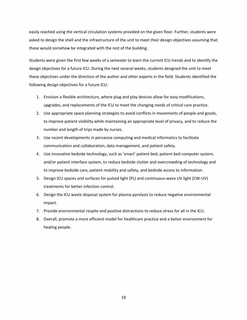
Students were given the first few weeks of a semester to learn the current ICU trends and to identify the
design objectives for a future ICU. During the next several weeks, students designed the unit to meet
these objectives under the direction of the author and other experts in the field. Students identified the
following design objectives for a future ICU:
1. Envision a flexible architecture, where plug and play devices allow for easy modifications,
upgrades, and replacements of the ICU to meet the changing needs of critical care practice.
2. Use appropriate space planning strategies to avoid conflicts in movements of people and goods,
to improve patient visibility while maintaining an appropriate level of privacy, and to reduce the
number and length of trips made by nurses.
3. Use recent developments in pervasive computing and medical informatics to facilitate
communication and collaboration, data management, and patient safety.
4. Use innovative bedside technology, such as ‘smart’ patient bed, patient bed computer system,
and/or patient interface system, to reduce bedside clutter and overcrowding of technology and
to improve bedside care, patient mobility and safety, and bedside access to information.
5. Design ICU spaces and surfaces for pulsed light (PL) and continuous-wave UV light (CW-UV)
treatments for better infection control.
6. Design the ICU waste disposal system for plasma pyrolysis to reduce negative environmental
impact.
7. Provide environmental respite and positive distractions to reduce stress for all in the ICU.
8. Overall, promote a more efficient model for healthcare practice and a better environment for
healing people.

20
Figure 3: Students use the floor plate shown in this figure for their ICU. They define a modular building
system for the ICU using 2’X2’ vertical and horizontal grids.
Studio outcomes
Built-in flexibility
In order to create a flexible ICU, students propose a flexible, modular building system. The system uses
plug-and-play devices for easy modifications, upgrades, and replacements of the components, sub-
systems, and systems of the ICU in order to meet the changing needs of critical care practice. The
system uses 2’x2’ vertical and horizontal grids [Figures 3 & 4]. Students use this particular module for
the grid because many building materials and components currently available in the market can easily
be fitted onto this grid. Students also create a kit of parts made up of framing units and panel units of
2’X2’ module [Figure 5]. These pieces can be mixed and matched manually because of their convenient
size. Therefore, the unit can be easily reconfigured when needed. Most often, the reconfiguration
process may involve making minor changes to walls and ceilings. On rare occasions, this may involve
changing the configuration of the unit altogether to accommodate the surge in patient population
because of a manmade or a natural disaster. Wall units of the system are pre-plumbed for utility and
can be plugged into the medical gas hubs located in the ceiling. As soon as the wall units make contact
with the 2’x2’ electrical grid located in the ceiling [Figure 4], it automatically brings power down through

21
the wall conduit into the space. As a result, this building system makes it possible to place a wall
anywhere on the grid and still gain access to medical gases and electricity.
Figure 4: The reflected ceiling plan of the ICU showing different utility hubs.

22
Figure 5: The kit of parts of the ICU. These pieces can be mixed and matched manually because of their
convenient size. Therefore, the unit can be easily reconfigured when needed.
CW-CV lighting and PL for Infection control
Students incorporate a combination of CW-CV and PL for disinfecting patient rooms. CW-CV will
continuously disinfect individual spaces within the ICU. While systems built in walls may primarily emit
such light, work surfaces, instrument panels, and interface devices that typically spread germs may be
self-illuminated with CW-CV and thus become self-disinfecting.
In circumstances where a high level of disinfection is needed, PL is utilized. In lieu of mobile units
currently available in the market, in future it may be beneficial to incorporate such lighting into building
infrastructure. Such incorporation may allow the system to completely clean a space between
occupations. By automating disinfection practices, many of the germ spreading practices or simply staff
malpractices may be eliminated.

23
Because the CW-CV and PL disinfect by way of lighting surfaces, space geometry and surface
smoothness become essential. Thus, students use curvilinear shaped crown and base mouldings along
with semi-reflective surfaces to ensure that each type of disinfecting light reaches every corner of the
patient room [Figure 6].
In addition to CW-CV and PL, students also use a low-pressure plasma disinfector, a technology that may
soon be available in the market, at the patient room entrance. These units are equipped with a motion
sensor and a prompt. If a person passes by a disinfector without using it, the device notifies the person
that she needs to disinfect her hands before entering the room [Figure 19].
Figure 6: Students use curvilinear shaped crown and base mouldings along with semi-reflective surfaces
in the patient room ensuring that each type of disinfecting light reaches every corner of the room.
Intelligent lighting systems for different functions
Spaces within an ICU have different lighting needs. For example, in patient rooms bright task lighting is
needed for procedures; soft and indirect lighting is needed for patient and family comfort; and natural

24
light or broad spectrum artificial light is needed for the patient’s circadian rhythm. In contrast, in staff
work area, task lighting is primarily needed. After developing matrices showing lighting needs for
different spaces in the ICU [Figure 7], students propose an intelligent digital lighting management
system that would allow users to choose among various “scenes” based on their current mood or task
need [Figures 8 & 9]. Additionally, they envision that data bands worn by the patient may be used to
send signals to the lighting module to inform it of sleeping schedules and other scenarios that may be
encountered. The interface of such an intelligent digital lighting management system can be mounted at
multiple places in the patient room and, if necessary, can be engaged with various mobile devices as
well. Students propose to use light emitting diode (LED) panels composed of numerous LEDs for
different types of lighting scenarios within a space [Figure 10]. Such light emitting panels may be
incorporated into the grid of the building system in any orientation, including walls, ceilings, and floors
[Figure 11].

25
Figure 7: The matrices in this figure show the lighting needs for different spaces in the ICU. It also shows the
primary and secondary users of these spaces, and the color and directionality of lighting needed for these users.
Figure 8: The conceptual and integrated intelligent digital lighting management interfaces.
(1) (2)

26
(3)
Figure 9: Different lighting scenarios. (1) Lighting for procedures. (2) Lighting for routine work. (3)
Lighting for sleep time.
Figure 10: A light emitting diode (LED) panel may be composed of numerous LEDs for different types of
lighting scenarios within a space.

27
Figure 11: Different types of lighting panels. (1) Basic illumination panel. (2) Recessed light strip. (3)
Extruded wall washer. (4) Direct spot. (5) Horizontal surface lighting.
Waste disposal system
Students use pneumatic waste collection systems for transporting waste from the unit to an on-site
plasma pyrolysis treatment unit [for details see above]. Such systems have been in use for some years
now in Roosevelt Island, New York and Walt Disney World, Orlando. The collection points of the
pneumatic systems can be located in the patient room and/or at some common locations within the
unit. When located within the patient room, these collection points may eliminate the need to carry any
waste out of the patient room, thus eliminating the risk of contamination. In its simplest form, there can
be only one pneumatic collection system that takes all ICU wastes to the treatment unit. In its more
complex form, there can be more than one collection system for hazardous medical wastes, recyclable
wastes, and laundry. In this particular instance, student choose two separate collection systems—one
for hazardous medical wastes and the other for laundry [Figure 12]. Wastes are sorted and put in
appropriate bags in the patient room, and are deposited into appropriate inlets located in the room. The
pneumatic systems take hazardous wastes directly to where it needs to. These inlets can be color coded
for safety [Figure 13]. Automatic prompts can also be used to notify the kind of wastes an inlet takes as
its lid is opened for a waste deposit. Additionally, student uses CW-UV lighting at these inlets to make
sure the surfaces around them are kept free of germs.

28
Figure 12: Pneumatic waste collection systems. (1) The medical waste is taken out of the building to a
remote plasma pyrolysis treatment plant. (2) The medical waste is taken to a on-site plasma pyrolysis
treatment plant.
‘Smart’ surfaces
Students use ‘smart’ surfaces for multiple functions within an ICU. These surfaces are enhanced with
computer capabilities and wireless communication devices. In addition to the computers located on
carts, in patient rooms, nurse workstations, or offices, smart surfaces can also work as computers. An
architectural surface, a countertop, or a bedside table could potentially become a smart surface to be
used by the medical staff as well as patients and families. All these smart surfaces are treated as nodes
in a network, and patient information can be pulled up on any one of these surfaces within the facility
with appropriate access code. The medical staff can carry a PDA that is in continuous communication
with these smart surfaces to have all the patient information at their fingertips. All of the smart surfaces
within the medical facility also constantly share data with each other. For example, as the vitals and
other measurements are being taken periodically on a patient, that data are automatically stored and
can be pulled up on any smart surface in the facility. This also means that when a patient is being
transported from one department to another the patient’s chart will be available not only in the unit but
also in any other department within the building.
The smart surfaces within the patient rooms can be put on the integrated head wall system to display
patient data [Figure 13]. They can also be put on the footwall for use by clinicians to explain clinical care

29
related issues to the patient and family, or for use by the patient and family to gain access to
entertainment [Figure 14]. Because everyone can use these surfaces, security needs to be considered.
Advanced biometrics can be used to determine the level of access for someone to protect patient
information and to insure that someone without proper identification is not able to view private medical
information. The placement of these surfaces is important to consider as well. These surfaces need to be
strategically placed, and privacy filters can be used on portions of the surface to insure appropriate
privacy and security needs.
This concept of smart surface can be comparable to what we find in an airport today, where information
display panels are distributed everywhere to be seen by all. However, it is assumed that smart surfaces
in an ICU or a hospital can be only accessed by authorized personnel or people on demand. Otherwise,
they would display general information for all.
Figure 13: The smart surface at the integrated headwall system in its idle state, and the waste collection
inlets in the patient room.

30
Figure 14: The multi-touch surface on the foot wall of the patient room can be used as a communication
and collaboration tool for the patient, family, and staff. It can also be used as a form of entertainment
for the patient and family.
Smart patient bed
Students equip the smart patient bed with a computer system. As in any other patient bed computer
systems currently being developed by manufacturers, this computer system stays with the patient as
s/he is moved from one place to another. It carries the patient’s information with it. It also has built-in
monitoring devices eliminating the need of complex wiring. Further, it is able to receive data from other
monitors wirelessly. The bed has two interface panels—one located on the side rail for the patient and
the other on the foot board for the clinician. The foot board of the board is also equipped with a smart
surface to access the patient’s information [Figure 15]. The foot board can be pulled up when the
clinician needs to use the smart surface.
Students also equip the smart patient bed with the most frequently used life support systems including
med-gas storage, external pacemaker, mechanical ventilator, defibrillator, and the dialysis equipment.
Additionally, it includes a rechargeable battery with enough power to run these systems when

31
transferring the patient from one location to another. These systems are stored in drawers in the lower
part of the bed, and can be pulled out if needed [Figure 16].
The modular wall system in the patient room serves as an integrated headwall system when equipped
with a smart surface. The headwall is also used as the docking station for smart patient beds. Housed
within these walls are electrical and data connections, as well as medical gas connections [Figure 17].
When the patient bed is docked, it acts like a normal patient bed, with the patient’s information
accessible from the smart headwalls. It is during its docking position the batteries for the life support
systems housed within the bed are also recharged. Even in this docking position, the bed can be rotated
as needed because of the swivel, extendible arm that connects the bed to the wall. When undocked, the
bed serves as an independent unit, capable of storing and displaying patient information and housing
necessary medical equipment [Figure 18].
Students hope that the smart patient bed would help eliminate the clutter caused by all the wires
running from the life support systems and monitors to the patient. It would also help save space in the
patient room by eliminating the need to use medical equipment on wheels or carts. This space may
become very important during a lifesaving procedure. Additionally, it would make charting, ordering,
and accessing the patient’s information easier. By providing patient information at the bedside, it would
also help improve collaboration and communication among patients, families, and clinicians. Further,
when equipped with a barcode reader it could help reduce errors and streamline billing processes
through monitoring any supplies delivered to the patient. In short, students anticipate that their smart
patient bed may significantly transform the medical care at the bedside.
(1) (2)

32
Figure 15: The smart patient bed. (1) The patient information interface in its regular position. (2) The
patient information interface is pulled out.
Figure 16: The smart patient bed equipment layout.

33
Figure 17: Details of the docking interface for the smart patient bed at the integrated headwall system.
Figure 18: Different positions of the smart patient bed.
Patient room design
With all the components, sub-systems, and systems in place, student now conceive the patient room of
the future to have three zones. In the staff zone, which is located in and around the entrance doorway,
they include a low pressure plasma hand disinfector with a motion sensor and a warning device. They
use smart surface for a part of the glass sliding door to display the patient’s name and status, the name
and picture of the attending nurse, and the name and picture of the family member. Immediately inside,
students put the digital environment control interface, the inlets for the pneumatic waste collection
system, and one RFID-enabled supply storage [Figure 19].
In the patient area, students include a digital headboard on the integrated headwall system, and a smart
patient bed. On the foot wall, they include a smart surface that always show the date and time for the
patient and others. When not in use by the clinician to explain care related issues to the patient and
family, the surface may display a soothing video of nature [Figures 21 & 23]. When the patient is fast
asleep, the surface may be used by the family for recreation.
In the family area, students provide a soft pullout seating, dimmable exterior glazing for heat gain and
glare control, a hand disinfector, and a toilet equipped with the CW-CV and PL treatment systems.

34
Figure 19: In the staff zone of the patient room, which is located in and around the entrance doorway,
Students include a low pressure plasma hand disinfector with a motion sensor and a warning device.
They use smart surface for a part of the glass sliding door to display the patient’s name and status, the
name and picture of the attending nurse, and the name and picture of the family member. Immediately
inside, students put the digital environment control interface, the inlets for the pneumatic waste
collection system (not shown in this figure), and one RFID-enabled supply storage . Next to the storage a
smart surface can be seen.
Unit layout options
Students divide their ICU into three zones: the clinical zone with patient beds/rooms and clinical support
functions; the staff area with staff lounge, lockers, offices, conference spaces, and storage spaces; and
the family area with toilets and an information center equipped with smart surfaces. Since the unit is
designed using plug a play devices, students are able to configure the clinical area of the unit for
different scenarios. In the normal scenario, the unit has 16 private patient rooms with individual toilets
and family spaces, one centralized nurse station, and one observation unit for every two rooms [Figures
20 & 21]. This layout allows direct visibility of the patient from the nurse station and observation units.

35
In another, students change some of the private patient rooms to two-bed patient rooms to be
operated as step-down units. In this configuration, the unit may be able to accommodate unusual serge
in patient population [Figures 22 & 23]. In the third scenario, students reconfigure the unit as an open
bed unit with as many as 40 beds by removing the panels for emergency mass critical care. In this
configuration, they still keep the toilets and the disinfectant devices within the unit [Figures 24 & 25]. It
may be worth noting here that in all these scenarios, the locations of plumbing and waste collection
inlets remain unchanged.
Figure 20: The ICU layout with 16 private patient rooms.

36
Figure 21: A view of a private patient room.

37
Figure 22: The ICU layout with private and semi-private patient rooms.
Figure 23: A view of a semi-private room.

38
Figure 24: The ICU with open ward layout.
Figure 25: A view of the open ward ICU.

39
CONCLUSION
The practice of critical care medicine has made significant progress during the last fifty years or so. No
doubt, innovations in medical and information technology have been at the core of this progress.
However, the design of ICUs has not been able to keep up with this rapid pace of progress of the
practice of critical care medicine. As more technologies become available to practice critical care
medicine, ICUs become increasingly crowded, complicated, and confusing. The design of ICUs in general
fails to support effective interdisciplinary communications and collaborations and easy hand-offs
between providers. Information technology and medical informatics promise to bring patient
information closer to caregivers, but ICUs cannot support effective use of this information because of
environmental design limitations. Better technologies are available for disinfecting ICUs, but they cannot
be used in ICUs for environmental design limitations as well. The design of ICUs in general does not
provide user-friendly human-technology interfaces, thus causing stress among clinicians with negative
outcomes. The list of environmental design limitations get bigger as the technology for the practice of
critical care medicine gets better. As a result, in spite of all medical and technological innovations critical
care patients are still unsafe, and the quality of critical care still has much room for improvement.
As students of this design studio correctly point out, one reason why ICU design fails to keep pace with
the developments in critical care medicine is that hospitals and designers simply use technology as an
additive element, in which devices are placed into a space as an afterthought to the architecture. To
overcome this, they must accept the idea that technology has the ability to shape architecture in a way
that promotes a more efficient healthcare practice and a better environment for healing people. As the
practice of critical care medicine rapidly advances, it is necessary to take a new approach to integrate
innovations made in practice with ICU design. Traditional building systems, subsystems, and
components do not allow ICUs to become flexible enough to accommodate innovations as they occur.
Therefore, there is an urgent need to reconsider these building systems, sub-systems and components
in a new way. The student of this studio takes this bold step. They take what is already available and
simply suggest new ways to integrate them for a better ICU of the future. Such integration may work
only if all the stakeholders join force to harness the power of innovations in ICUs in a way that supports
everyday practice of critical care medicine.

40
REFERENCES
1. Angus D, Barnato A, Linde-Zwirble W et al: Use of intensive care at the end of life in the United
States: an epidemiologic study. Crit Care Med 2004; 32:638–643
2. Rashid M: Environmental Design for Patient Families in Intensive Care Units. Journal of Healthcare
Engineering – Special issue on critical care and intensive care unit 2010; 1(3):367-397
3. Byers JF: Family discussion groups, a way to meet the needs of the ICU patient’s family. Crit Care
Nurse 1983; 3(1): 16, 20
4. Hodovanic BH, Reardon D, Reese W, Hedges B: Family crisis intervention program in the medical
intensive care unit. Heart & Lung 1984; 13: 243–9
5. Molter NC: Needs of relatives of critically ill patients: a descriptive study. Heart & Lung 1979; 8:332–
9
6. Elsayed S, Greenland B, Joyner B, et al: Getting on board: training activities to promote the practice
of family-centered care, 2nd ed., Association for the Care of Children’s Health, Bethesda, MD, 1995
7. Institute of Medicine: Crossing the Quality Chasm: A New Health System for the 21st Century.
National Academies Press, Washington, DC, 2001
8. Pronovost P: A passion for quality. In: Care in ICU. The National Coalition on Health Care and the
Institute for Healthcare Improvement, 2002
9. Angus DC: Caring for the critically ill patient: challenges and opportunities. JAMA 2007; 298(4):456-7
10. Provonost PJ, Needham DM, Water H, et al: Intensive care unit physician staffing: Financial modeling
of the Leapfrog Standard. Crit Care Med 2006; 34(3):S18-24
11. American Association of Colleges of Nursing: Nursing shortage fact sheet, 2011
12. Institute of Medicine: To err is human: building a safer health system. The National Academies Press,
1999
13. Krishnan V: Infection control in the ICU. In: Critical Care: Just the Facts. Hall JB, Schmidt GA (Eds).
The McGraw-Hill Companies, Inc. 2007
14. Kelley MA, Angus D, Chalfin DB, et al: The Critical Care Crisis in the United States: A Report From the
Profession. Chest 2004; 125:1514–1517
15. Orwat C, Graefe A, Faulwasser T: Towards pervasive computing in health care – A literature review.
BMC Medical Informatics and Decision Making 2008, 8:26
16. Mayor M: Navox patents wireless voice-data technology. Wireless NewsFactor December 19,
2000. Available at: http://www.wirelessnewsfactor. com/perl/story/6171.html

41
Navox Awarded Key First Patent for its SVD Voice-Data Communication Technology Over
Wireless Channels. Business Wire, Dec 18, 2000. Available at :
http://www.highbeam.com/doc/1G1-68182970.html. Accessed on 03 Aug 2011.
17. Kontzer T: I-mode wireless Internet could be in U.S. by 2002. Information Week March 14, 2001.
Available at: http://www.informationweek.com/news/6505258. Accessed 03 Aug 2011
18. Bluetooth Web site. Available at: http:// www.bluetooth.com/
19. ElekTex Web site. Available at: http://www.elektex.com/
20. MIT Media Lab Group Projects Web page. Available at:
http://www.media.mit.edu/research/groups-projects
21. IEEE, Proceedings of the Third IEEE International Workshop on Visual Surveillance, Dublin, Ireland,
2000
22. MIT Media Lab Affective Computing Webpage. Available at: http://www.media.mit.edu/ affect/
23. Lahtela A: A Short Overview of the RFID Technology in Healthcare. IEEE Proceedings of the
Fourth International Conference on Systems and Networks Communications 2009, 165-69.
Downloaded from http://ieeexplore.ieee.org/stamp/stamp.jsp?tp=&arnumber=5279372 on 03
Aug 2011.
24. Legras A, Malvy D, Quinioux AI et al: Nosocomial infections: prospective survey of incidence in five
French intensive care units. Intensive Care Med 1998; 24: 1040–1046
25. Fridkin SK, Welbel SF, Weinstein RA: Magnitude and prevention of nosocomial infections in the
intensive care unit. Infect Dis Clin N Am 1997; 11: 479–496
26. Richards MJ, Edwards JR, Culver DH, Gaynes RP: Nosocomial infections in medical intensive care
units in the United States. Crit Care Med 1999; 27: 887–892
27. Chevret S, Hemmmer M, Carlet J, Langer M and the European Cooperative group on Nosocomial
Pneumonia: Incidence and risk factors of pneumonia in intensive care units. Intensive Care Med
1993; 19: 256–264
28. Bauer TM, Ofner E, Just HM, Just H, Daschner FD: An epidemiological study assessing the relative
importance of airborne and direct contact transmission of microorganisms in a medical intensive
care unit. J Hosp Infect 1990; 15: 301–309
29. Vicca AF: Nursing staff workload as a determinant of methicillin-resistant Staphylococcus aureus
spread in an adult intensive therapy unit. J Hosp Infect 1999; 43: 109–113
30. Dieckhaus KD, Cooper BW: Infection control concepts in critical care. Crit Care Clin 1998; 14: 55–70

42
31. Health Building Note 27: Intensive Therapy Unit. NHS Estates 1992 HMSO (formerly Hospital Building
Note 27, Department of Health and Social Security. 1974)
32. Standards for Intensive Care Units. Intensive Care Society 1997
33. Wedel S, Warren J, Harvey M, Hitchens Biel M, Dennis R: Guidelines for intensive care unit design.
Crit Care Med 1995; 23: 582–588
34. Ferdinande P, Members of the Task Force of the European Society of Intensive Care Medicine:
Recommendations on minimal requirements for Intensive Care Departments 1995; 1–26.
35. Ferdinande P: Recommendations on minimal requirements for Intensive Care Departments.
Intensive Care Med 1997; 23: 226–232
36. Goodman ER, Platt R, Bass R, et al: Impact of an environmental cleaning intervention on the
presence of methicillin-resistant Staphylococcus aureus and vancomycin-resistant enterococci on
surfaces in intensive care unit rooms. Infect Control Hosp Epidemiol 2008; 29:593-599
37. Carling PC, Briggs JL, Perkins J, Highlander D: Improved cleaning of patient rooms using a new
targeting method. Clin Infect Dis 2006; 42:385-388.
38. Gómez-López VM, Ragaert P, Debevere J, Devlieghere F: Pulsed light for food decontamination: a
review. Trends in Food Science & Technology 18 (2007) 464-473
39. MacGregor SJ, Rowan NJ, McIlvaney L, et al: Light inactivation of food related pathogenic bacteria
using a pulsed power source. Letters in Applied Microbiology 1998; 27, 67-70
40. Sharma RR, Demirci A: Inactivation of Escherichia coli O157:H7 on inoculated alfalfa seeds with
pulsed ultraviolet light and response surface modeling. Journal of Food Science 2003; 68:1448-1453
41. Roberts P, Hope A: Virus inactivation by high intensity broad spectrum pulsed light. Journal of
Virological Methods 2003; 110: 61-65
42. Rowan N J, MacGregor SJ, Anderson JG, et al: Pulsed-light inactivation of food-related
microorganisms. Applied and Environmental Microbiology 1999; 65:1312-1315
43. Marquenie D, Geeraerd AH, Lammertyn J, et al: Combinations of pulsed white light and UV-C or mild
heat treatment to inactivate conidia of Botrytis cinerea and Monilia fructigena. International Journal
of Food Microbiology 2003; 85: 185-196
44. Wekhof A: Disinfection with flash lamps. PDA Journal of Pharmaceutical Science and Technology
2000; 54:264-276
45. Hiramoto T: Method of sterilization. US Patent 4,464,336, 1984

43
46. Bintsis T, Litopoulou-Tzanetaki E, Robinson RK: Existing and potential application of ultraviolet light
in the food industryda critical review. Journal of the Science of Food and Agriculture 2000; 90:637-
645.
47. Bolton JR, Linden KG: Standardization of methods for fluence (UV dose) determination in bench-
scale UV experiments. Journal of Environmental Engineering 2003; 129:209-215
48. Crisosto CH, Seguel X, Michailides T: Comparing pulsated ultraviolet light and postharvest fungicide
for peach fruit decay control. Acta Horticulturae 1998; 465: 471-479
49. M Stibich, J Stachowiak, B Tanner, et al: Evaluation of a Pulsed-Xenon Ultraviolet Room Disinfection
Device for Impact on Hospital Operations and Microbial Reduction. Infection control and hospital
epidemiology 2011; 32(3):1-3
50. Fisher BE: Dissolving medical waste. Environmental Health Perspectives 1996, 104(7): 708-710
51. Nema SK, Ganeshprasad KS: Plasma pyrolysis of medical waste, Current Science 2002, 83(3): 271-278