technology focus electronics/computers - nasa technology focus: sensors 5 airport remote tower...
TRANSCRIPT

Technology Focus
Electronics/Computers
Software
Materials
Mechanics
Machinery/Automation
Manufacturing & Prototyping
Bio-Medical
Physical Sciences
Information Sciences
Books and Reports
07-06 July 2006
https://ntrs.nasa.gov/search.jsp?R=20110012907 2019-04-27T01:30:07+00:00Z


NASA Tech Briefs, July 2006 1
INTRODUCTIONTech Briefs are short announcements of innovations originating from research and develop-
ment activities of the National Aeronautics and Space Administration. They emphasizeinformation considered likely to be transferable across industrial, regional, or disciplinary linesand are issued to encourage commercial application.
Availability of NASA Tech Briefs and TSPsRequests for individual Tech Briefs or for Technical Support Packages (TSPs) announced herein shouldbe addressed to
National Technology Transfer CenterTelephone No. (800) 678-6882 or via World Wide Web at www2.nttc.edu/leads/
Please reference the control numbers appearing at the end of each Tech Brief. Information on NASA’s Innovative Partnerships Program (IPP), its documents, and services is also available at the same facility oron the World Wide Web at http://ipp.nasa.gov.
Innovative Partnerships Offices are located at NASA field centers to provide technology-transfer access toindustrial users. Inquiries can be made by contacting NASA field centers listed below.
Ames Research CenterLisa L. Lockyer(650) [email protected]
Dryden Flight Research CenterGregory Poteat(661) [email protected]
Goddard Space Flight CenterNona Cheeks(301) [email protected]
Jet Propulsion LaboratoryKen Wolfenbarger(818) [email protected]
Johnson Space CenterMichele Brekke(281) [email protected]
Kennedy Space CenterJim Aliberti(321) [email protected]
Langley Research CenterMartin Waszak(757) [email protected]
Glenn Research CenterRobert Lawrence(216) [email protected]
Marshall Space Flight CenterVernotto McMillan(256) [email protected]
Stennis Space CenterJohn Bailey(228) 688-1660 [email protected]
Carl Ray, Program ExecutiveSmall Business Innovation Research (SBIR) & Small Business Technology Transfer (STTR) Programs(202) [email protected]
Merle McKenzieInnovative Partnerships Program Office(202) [email protected]
NASA Field Centers and Program Offices


5 Technology Focus: Sensors5 Airport Remote Tower Sensor Systems
6 Implantable Wireless MEMS Sensors for Medical Uses
6 Embedded Sensors for Measuring SurfaceRegression
7 Coordinating an Autonomous Earth-ObservingSensorweb
8 Range-Measuring Video Sensors
9 Stability Enhancement of Polymeric Sensing FilmsUsing Fillers
10 Sensors for Using Times of Flight To MeasureFlow Velocities
11 Electronics/Computers11 Receiver Would Control Phasing of a Phased-
Array Antenna
12 Modern Design of Resonant Edge-Slot ArrayAntennas
13 Carbon-Nanotube Schottky Diodes
14 Simplified Optics and Controls for LaserCommunications
14 Coherent Detection of High-Rate Optical PPMSignals
15 Multichannel Phase and Power Detector
17 Software17 Using Satellite Data in Weather Forecasting: I
17 Using Dissimilarity Metrics To Identify InterestingDesigns
17 X-Windows PVT Widget Class
17 Shuttle Data Center File-Processing Tool in Java
17 Statistical Evaluation of Utilization of the ISS
19 Materials19 Nanotube Dispersions Made With Charged
Surfactant
19 Aerogels for Thermal Insulation of ThermoelectricDevices
20 Low-Density, Creep-Resistant Single-CrystalSuperalloys
23 Mechanics23 Excitations for Rapidly Estimating Flight-Control
Parameters
24 Estimation of Stability and Control Derivatives ofan F-15
25 Tool for Coupling a Torque Wrench to a RoundCable Connector
27 Machinery/Automation27 Ultrasonically Actuated Tools for Abrading Rock
Surfaces
27 Active Struts With Variable Spring Stiffness andDamping
29 Bio-Medical29 Multiaxis, Lightweight, Computer-Controlled
Exercise System
30 Dehydrating and Sterilizing Wastes UsingSupercritical CO2
31 Physical Sciences31 Alpha-Voltaic Sources Using Liquid Ga as
Conversion Medium
31 Ice-Borehole Probe
33 Alpha-Voltaic Sources Using Diamond asConversion Medium
33 White-Light Whispering-Gallery-Mode OpticalResonators
35 Books & Reports35 Controlling Attitude of a Solar-Sail Spacecraft
Using Vanes
35 Wire-Mesh-Based Sorber for RemovingContaminants From Air
07-06 July 2006
NASA Tech Briefs, July 2006 3
This document was prepared under the sponsorship of the National Aeronautics and Space Administration. Neither the United States Govern-ment nor any person acting on behalf of the United States Government assumes any liability resulting from the use of the information containedin this document, or warrants that such use will be free from privately owned rights.


NASA Tech Briefs, July 2006 5
Airport Remote Tower Sensor SystemsBetter weather information will be available for guiding approaches and landings.Ames Research Center, Moffett Field, California
Networks of video cameras, meteor-ological sensors, and ancillary elec-tronic equipment are under develop-ment in collaboration among NASAAmes Research Center, the FederalAviation Administration (FAA), andthe National Oceanic AtmosphericAdministration (NOAA). These net-works are to be established at and nearairports to provide real-time informa-tion on local weather conditions thataffect aircraft approaches and land-ings.
The prototype network is an airport-approach-zone camera system (AAZCS),which has been deployed at San Fran-cisco International Airport (SFO) andSan Carlos Airport (SQL). The AAZCSincludes remotely controlled colorvideo cameras located on top of SFOand SQL air-traffic control towers. The
cameras are controlled by the NOAACenter Weather Service Unit located atthe Oakland Air Route Traffic ControlCenter and are accessible via a secureWeb site. The AAZCS cameras can bezoomed and can be panned and tiltedto cover a field of view 220° wide. TheNOAA observer can see the sky condi-tion as it is changing, thereby makingpossible a real-time evaluation of theconditions along the approach zonesof SFO and SQL.
The next-generation network, de-noted a remote tower sensor system(RTSS), will soon be deployed at theHalf Moon Bay Airport and a version ofit will eventually be deployed at Los An-geles International Airport. In additionto remote control of video cameras viasecure Web links, the RTSS offers real-time weather observations, remote sens-
ing, portability, and a capability for de-ployment at remote and uninhabitedsites. The RTSS can be used at airportsthat lack control towers, as well as atmajor airport hubs, to provide syntheticaugmentation of vision for both localand remote operations under whatwould otherwise be conditions of low oreven zero visibility.
A prototype of a portable RTSS unit(see figure) includes a tripod, on whichare mounted the following subsystems:• A low-resolution pan/tilt/zoom color
video camera in a dome housing;• Ultrasonic sensors for measuring wind
velocity;• Temperature and relative-humidity
sensors;• A barometric pressure sensor;• A data-acquisition (data-logging) sub-
system for collecting sensor data;• An embedded Web video-image-data
server computer;• A wireless Ethernet module;• A battery power supply;• Solar photovoltaic panels to charge
the battery; and• A directional antenna for wireless
communication.In addition to portable units like thisone, the RTSS will include a high-resolu-tion camera mounted on a pre-existingairport tower.
It is envisioned that future RTSSswill be parts of dynamic virtual towersystems, which will be air-traffic-con-trol systems that will serve airportsthat lack control towers. In a virtualtower system, the information col-lected from a suite of RTSS unitswould be sent to a facility, locatedelsewhere than at an affected airport,where a team of air-traffic controllerscould utilize the information in per-forming real-time tower operations. Itis further envisioned that real-time in-tegration of data among pilots, air-craft, and virtual tower stations willbecome feasible.
Yet another development is that of areal-time, automated visibility-image-management system that uses RTSSs totrack changing airport and terminal
A Prototype RTSS Portable Unit includes sensor, power, and communication subsystems mounted ona 9-ft (≈2.7-m) tripod.
Technology Focus: Sensors

6 NASA Tech Briefs, July 2006
conditions. More specifically, this sys-tem processes RTSS image data, by useof advanced algorithms, to predicttrends in visibility. The image data areacquired, stored, and processed at 15-minute intervals. The processing ofthe data yields 15-minute updates of a
visibility-versus-time plot, on which vis-ibility is quantified on a suggestedscale of 0 to 1.
This work was done by David A. Maluf,Yuri Gawdiak, Christopher Leidichj, andRichard Papasin of Ames Research Centerand Peter B. Tran and Kevin Bass of QSS
Group, Inc. Further information is containedin a TSP (see page 1).
Inquiries concerning rights for the commer-cial use of this invention should be addressedto the Ames Technology Partnerships Divisionat (650) 604-2954. Refer to ARC-15029-1.
Implantable Wireless MEMS Sensors for Medical UsesIntegrated Sensing Systems, Inc., Ypsilanti, Michigan
Sensors designed and fabricated ac-cording to the principles of micro-electromechanical systems (MEMS)are being developed for several med-ical applications in outer space and onEarth. The designs of these sensors arebased on a core design family of pres-sure sensors, small enough to fit intothe eye of a needle, that are fabricatedby a “dissolved wafer” process. Thesensors are expected to be im-plantable, batteryless, and wireless.They would be both powered and in-terrogated by hand-held radio trans-
ceivers from distances up to about 6 in.(about 15 cm). One type of sensorwould be used to measure blood pres-sure, particularly for congestive heartfailure. Another type would be used tomonitor fluids in patients who have hy-drocephalus (high brain pressure).Still other types would be used to de-tect errors in delivery of drugs and tohelp patients having congestive heartfailure.
This work was directed by AlexanderChimbayo of Integrated Sensing Systems,Inc. under a NASA Small Business Inno-
vation Research (SBIR) contract monitoredby Langley Research Center. For furtherinformation, contact:
Dr. Alexander Chimbayo Integrated Sensing Systems, Inc.391 Airport Industrial DriveYpsilanti, MI 48198Phone No.: (734) 547-9896 Ext. 116 E-mail: [email protected] to SBIR-0010, volume and number
of this NASA Tech Briefs issue, and thepage number.
Embedded Sensors for Measuring Surface RegressionElectrical-resistance measurements are translated into real-time material thickness and surfaceregression data for hybrid fuels, solid propellants, and ablative materials. Stennis Space Center, Mississippi
The development and evaluation ofnew hybrid and solid rocket motors re-quires accurate characterization of thepropellant surface regression as a func-tion of key operational parameters.These characteristics establish the pro-pellant flow rate and are prime designdrivers affecting the propulsion systemgeometry, size, and overall perform-ance. There is a similar need for the de-velopment of advanced ablative materi-als, and the use of conventionalablatives exposed to new operationalenvironments. The Miniature SurfaceRegression Sensor (MSRS) was devel-oped to serve these applications. It isdesigned to be cast or embedded in thematerial of interest and regresses alongwith it. During this process, the resist-ance of the sensor is related to its instan-taneous length, allowing the real-timethickness of the host material to be es-tablished. The time derivative of thisdata reveals the instantaneous surfaceregression rate.
The MSRS could also be adapted toperform similar measurements for a va-riety of other host materials when it isdesired to monitor thicknesses and/orregression rate for purposes of safety,operational control, or research. Forexample, the sensor could be used tomonitor the thicknesses of brake lin-ings or racecar tires and indicate whenthey need to be replaced. At the timeof this reporting, over 200 of these sen-sors have been installed into a variety ofhost materials.
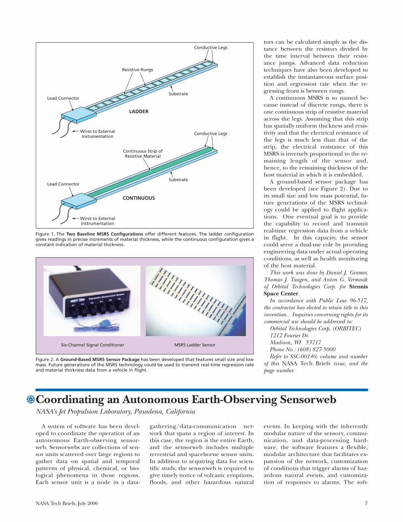
An MSRS can be made in either of twoconfigurations, denoted “ladder” and“continuous” (see Figure 1). A ladderMSRS includes two highly electrically con-ductive legs, across which narrow strips ofelectrically resistive material are placed atsmall increments of length. These stripsresemble the rungs of a ladder and areelectrically equivalent to many tiny resis-tors connected in parallel. A substrate ma-terial provides structural support for thelegs and rungs. The instantaneous sensor
resistance is read by an external signalconditioner via wires attached to the con-ductive legs on the non-eroding end ofthe sensor. The sensor signal can be trans-mitted from inside a high-pressure cham-ber to the ambient environment, usingcommercially available feedthrough con-nectors. Miniaturized internal recordersor wireless data transmission could alsopotentially be employed to eliminate theneed for producing penetrations in thechamber case.
The rungs are designed so that as eachsuccessive rung is eroded away, the resist-ance changes by an amount that yields areadily measurable signal larger than thebackground noise. (In addition, signal-conditioning techniques are used in pro-cessing the resistance readings to miti-gate the effect of noise.) Hence, eachdiscrete change of resistance serves to in-dicate the arrival of the regressing hostmaterial front at the known depth of theaffected resistor rung. The average rateof regression between two adjacent resis-
tors can be calculated simply as the dis-tance between the resistors divided bythe time interval between their resist-ance jumps. Advanced data reductiontechniques have also been developed toestablish the instantaneous surface posi-tion and regression rate when the re-gressing front is between rungs.
A continuous MSRS is so named be-cause instead of discrete rungs, there isone continuous strip of resistive materialacross the legs. Assuming that this striphas spatially uniform thickness and resis-tivity and that the electrical resistance ofthe legs is much less than that of thestrip, the electrical resistance of thisMSRS is inversely proportional to the re-maining length of the sensor and,hence, to the remaining thickness of thehost material in which it is embedded.
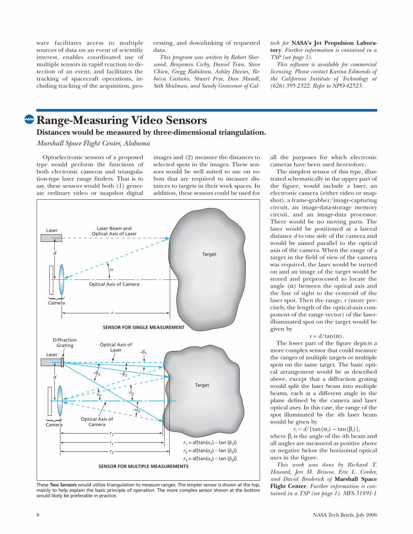
A ground-based sensor package hasbeen developed (see Figure 2). Due toits small size and low mass potential, fu-ture generations of the MSRS technol-ogy could be applied to flight applica-tions. One eventual goal is to providethe capability to record and transmitreal-time regression data from a vehiclein flight. In this capacity, the sensorcould serve a dual-use role by providingengineering data under actual operatingconditions, as well as health monitoringof the host material.
This work was done by Daniel J. Gramer,Thomas J. Taagen, and Anton G. Vermaakof Orbital Technologies Corp. for StennisSpace Center.
In accordance with Public Law 96-517,the contractor has elected to retain title to thisinvention. Inquiries concerning rights for itscommercial use should be addressed to:
Orbital Technologies Corp. (ORBITEC)1212 Fourier Dr. Madison, WI 53717Phone No.: (608) 827-5000Refer to SSC-00140, volume and number
of this NASA Tech Briefs issue, and thepage number.
NASA Tech Briefs, July 2006 7
Figure 1. The Two Baseline MSRS Configurations offer different features. The ladder configurationgives readings in precise increments of material thickness, while the continuous configuration gives aconstant indication of material thickness.
Resistive Rungs
Conductive Legs
SubstrateLead Connector
Wires to ExternalInstumentation
Continuous Strip of Resistive Material
LADDER
CONTINUOUS
Substrate Lead Connector
Conductive Legs
Wires to External Instrumentation
SSC-00140 Fig 1ABPI
4-6-05 bs
Six-Channel Signal Conditioner MSRS Ladder Sensor
SSC-00140 Fig 2ABPI
3-30-06 ca
Figure 2. A Ground-Based MSRS Sensor Package has been developed that features small size and lowmass. Future generations of the MSRS technology could be used to transmit real-time regression rateand material thickness data from a vehicle in flight.
Coordinating an Autonomous Earth-Observing SensorwebNASA’s Jet Propulsion Laboratory, Pasadena, California
A system of software has been devel-oped to coordinate the operation of anautonomous Earth-observing sensor-web. Sensorwebs are collections of sen-sor units scattered over large regions togather data on spatial and temporalpatterns of physical, chemical, or bio-logical phenomena in those regions.Each sensor unit is a node in a data-
gathering/data-communication net-work that spans a region of interest. Inthis case, the region is the entire Earth,and the sensorweb includes multipleterrestrial and spaceborne sensor units.In addition to acquiring data for scien-tific study, the sensorweb is required togive timely notice of volcanic eruptions,floods, and other hazardous natural
events. In keeping with the inherentlymodular nature of the sensory, commu-nication, and data-processing hard-ware, the software features a flexible,modular architecture that facilitates ex-pansion of the network, customizationof conditions that trigger alarms of haz-ardous natural events, and customiza-tion of responses to alarms. The soft-
8 NASA Tech Briefs, July 2006
ware facilitates access to multiplesources of data on an event of scientificinterest, enables coordinated use ofmultiple sensors in rapid reaction to de-tection of an event, and facilitates thetracking of spacecraft operations, in-cluding tracking of the acquisition, pro-
cessing, and downlinking of requesteddata.
This program was written by Robert Sher-wood, Benjamin Cichy, Daniel Tran, SteveChien, Gregg Rabideau, Ashley Davies, Re-becca Castaño, Stuart Frye, Dan Mandl,Seth Shulman, and Sandy Grosvenor of Cal-
tech for NASA’s Jet Propulsion Labora-tory. Further information is contained in aTSP (see page 1).
This software is available for commerciallicensing. Please contact Karina Edmonds ofthe California Institute of Technology at(626) 395-2322. Refer to NPO-42523.
Optoelectronic sensors of a proposedtype would perform the functions ofboth electronic cameras and triangula-tion-type laser range finders. That is tosay, these sensors would both (1) gener-ate ordinary video or snapshot digital
images and (2) measure the distances toselected spots in the images. These sen-sors would be well suited to use on ro-bots that are required to measure dis-tances to targets in their work spaces. Inaddition, these sensors could be used for
all the purposes for which electroniccameras have been used heretofore.
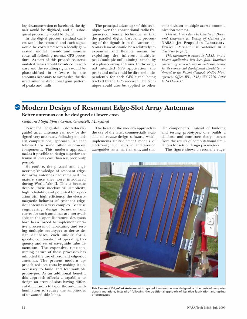
The simplest sensor of this type, illus-trated schematically in the upper part ofthe figure, would include a laser, anelectronic camera (either video or snap-shot), a frame-grabber/image-capturingcircuit, an image-data-storage memorycircuit, and an image-data processor.There would be no moving parts. Thelaser would be positioned at a lateraldistance d to one side of the camera andwould be aimed parallel to the opticalaxis of the camera. When the range of atarget in the field of view of the camerawas required, the laser would be turnedon and an image of the target would bestored and preprocessed to locate theangle (α) between the optical axis andthe line of sight to the centroid of thelaser spot. Then the range, r (more pre-cisely, the length of the optical-axis com-ponent of the range vector) of the laser-illuminated spot on the target would begiven by
r = d/tan(α).The lower part of the figure depicts a
more complex sensor that could measurethe ranges of multiple targets or multiplespots on the same target. The basic opti-cal arrangement would be as describedabove, except that a diffraction gratingwould split the laser beam into multiplebeams, each at a different angle in theplane defined by the camera and laseroptical axes. In this case, the range of thespot illuminated by the ith laser beamwould be given by
ri = d/[tan(αi) – tan(βi)],where βi is the angle of the ith beam andall angles are measured as positive aboveor negative below the horizontal opticalaxes in the figure.
This work was done by Richard T.Howard, Jeri M. Briscoe, Eric L. Corder,and David Broderick of Marshall SpaceFlight Center. Further information is con-tained in a TSP (see page 1). MFS-31891-1
These Two Sensors would utilize triangulation to measure ranges. The simpler sensor is shown at the top,mainly to help explain the basic principle of operation. The more complex sensor shown at the bottomwould likely be preferable in practice.
Target
MFS-31891ABPI
10-22-03 es
Laser Laser Beam andOptical Axis of Laser
Optical Axis of Camera
Camera
d
r
SENSOR FOR SINGLE MEASUREMENT
Laser
Optical Axis ofLaser
Optical Axis ofCameraCamera
d
r1 = d/[tan(α1) – tan (β1)]
r2 = d/[tan(α2) – tan (β2)]
r3 = d/[tan(α3) – tan (β3)]
r3
r1
r2
SENSOR FOR MULTIPLE MEASUREMENTS
DiffractionGrating
–β3
α2α1
–α3
–β2
–β1
Target
α
Range-Measuring Video SensorsDistances would be measured by three-dimensional triangulation.Marshall Space Flight Center, Alabama

NASA Tech Briefs, July 2006 9
Stability Enhancement of Polymeric Sensing Films Using FillersEnhanced stability of polymer sensing films is achieved by adding colloidal fillers.NASA’s Jet Propulsion Laboratory, Pasadena, California
Experiments have shown the stabilityenhancement of polymeric sensing filmson mixing the polymer with colloidalfiller particles (submicron-sized) of car-bon black, silver, titanium dioxide, andfumed silicon dioxide. The polymer filmsare candidates for potential use as sensingmedia in micro/nano chemical sensor de-vices. The need for stability enhancementof polymer sensing films arises because
such films have been found to exhibit un-predictable changes in sensing activityover time, which could result in a possiblefailure of the sensor device.
The changes in the physical proper-ties of a polymer sensing film caused bythe sorption of a target molecule can bemeasured by any of several establishedtransduction techniques: electrochemi-cal, optical, calorimetric, or piezoelec-
tric, for example. The transduction tech-nique used in the current polymer stabil-ity experiments is based on piezoelectricprinciples using a quartz-crystal micro-balance (QCM). The surface of theQCM is coated with the polymer, andthe mass uptake by the polymer filmcauses a change in the oscillating fre-quency of the quartz crystal.
The polymer used for the currentstudy is ethyl cellulose. The polymer/polymer composite solutions were pre-pared in 1,3 dioxolane solvent. The fillerconcentration was fixed at 10 weightpercent for the composites. The poly-mer or polymer composite solutionswere cast on the quartz crystal having afundamental frequency of about 6 MHz.The coated crystal was subjected to amultistage drying process to remove allmeasurable traces of the solvent.
In each experiment, the frequency ofoscillation was measured while theQCM was exposed to clean, dry, flowingair for about 30 minutes, then to aircontaining a known concentration ofisopropanol for about 30 minutes, thenagain to clean dry air for about 30 min-utes, and so forth. This cycle of meas-urements for varying isopropanol con-centrations was repeated at intervals forseveral months.
The figure depicts some of the sensingfilm stability results for ethyl cellulosepolymer, ethyl cellulose-carbon black,and ethyl cellulose-silicon dioxide com-posite systems. An ethyl cellulose film ex-hibited a marked decline in response inthe first few months of study and settledto a steady average response after aboutfour months. However, response variedwidely around the average response forethyl cellulose film. In contrast, ethyl cel-lulose-carbon black and ethyl cellulose-silicon dioxide composites also declinedin the early months, but showed more re-peatable sensing film activity after theinitial decline. Similar trends were ob-served in experiments for ethyl cellulose-titanium dioxide and ethyl cellulose-sil-ver composites.
This work was done by Brian Lin, AbhijitShevade, Margaret Amy Ryan, Adam Kisor,Shiao-Pin Yen, Kenneth Manatt, MargieHomer, and Jean-Pierre Fleurial of Caltech forNASA’s Jet Propulsion Laboratory. Fur-ther information is contained in a TSP (seepage 1). NPO-40518
Graphs Show Sensing Stabilities of ethyl cellulose polymer and ethyl cellulose-composite sensing filmsto the detection of 600 ppm of isopropanol. As compared to the stability of ethyl cellulose polymer,the ethyl cellulose-carbon composite and ethyl cellulose-silicon dioxide composite show greater stabil-ity with time. The lines drawn are to guide the eye.
00
5
10
15
20
25
30
50 100
Age of Chip, Days
Ethyl Cellulose Polymer
Sorp
tio
nA
ctiv
ity,
Hz
150 200 250
00
5
10
15
20
25
30
50 100
Age of Chip, Days
Ethyl Cellulose-Carbon Black Composite
Sorp
tio
nA
ctiv
ity,
Hz
150 200 250
NPO40518 ABPI
3-8-04 bs
REVISED 08-18-05 LE
00
5
10
15
20
25
30
20 40
Age of Chip, Days
Ethyl Cellulose-Silicon Dioxide Composite
Sorp
tio
nA
ctiv
ity,
Hz
60 80 100

10 NASA Tech Briefs, July 2006
Sensors for Using Times of Flight To Measure Flow VelocitiesNo calibrations are needed to use these thin-film sensors.John H. Glenn Research Center, Cleveland, Ohio
Thin-film sensors for measuring flowvelocities in terms of times of flight areundergoing development. These sensorsare very small and can be mounted flushwith surfaces of airfoils, ducts, and otherobjects along which one might need tomeasure flows. Alternatively or in addi-tion, these sensors can be mounted onsmall struts protruding from such surfacesfor acquiring velocity measurements atvarious distances from the surfaces for thepurpose of obtaining boundary-layer flow-velocity profiles.
These sensors are related to, but notthe same as, hot-wire anemometers.Each sensor includes a thin-film, elec-trically conductive loop, along whichan electric current is made to flow toheat the loop to a temperature abovethat of the surrounding fluid. Instanta-
neous voltage fluctuations in segmentsof the loop are measured by means ofelectrical taps placed at intervals alongthe loop. These voltage fluctuationsare caused by local fluctuations in elec-trical resistance that are, in turn,caused by local temperature fluctua-tions that are, in turn, caused by fluctu-ations in flow-induced cooling and,hence, in flow velocity.
The differential voltage as a functionof time, measured at each pair of taps,is subjected to cross-correlation pro-cessing with the corresponding quanti-ties measured at other pairs of taps atdifferent locations on the loop. Thecross-correlations yield the times takenby elements of fluid to travel betweenthe pairs of taps. Then the componentof velocity along the line between any
two pairs of taps is calculated simply asthe distance between the pairs of tapsdivided by the travel time. Unlike inthe case of hot-wire anemometers,there is no need to obtain calibrationdata on voltage fluctuations versus ve-locity fluctuations because, at least inprinciple, the correlation times are in-dependent of the calibration data.
This work was done by Gutave Fralick,John D. Wrbanek, and Danny Hwang ofGlenn Research Center and James Tursoof QSS Inc. Further information is containedin a TSP (see page 1).
Inquiries concerning rights for the commer-cial use of this invention should be addressedto NASA Glenn Research Center, InnovativePartnerships Office, Attn: Steve Fedor, MailStop 4–8, 21000 Brookpark Road, Cleve-land, Ohio 44135. Refer to LEW-17944-1.

NASA Tech Briefs, July 2006 11
Electronics/Computers
Receiver Would Control Phasing of a Phased-Array AntennaPeaks and nulls would be aimed to optimize reception.NASA’s Jet Propulsion Laboratory, Pasadena, California
In a proposed digital signal-process-ing technique, a radio receiver wouldcontrol the phasing of a phased-array an-tenna to aim the peaks of the antennaradiation pattern toward desired signalsources while aiming the nulls of the pat-tern toward interfering signal sources.The technique was conceived for use ina Global Positioning System (GPS) re-ceiver, for which the desired signalsources would be GPS satellites and typi-
cal interference sources would be terres-trial objects that cause multipath propa-gation. The technique could also beused to optimize reception in spread-spectrum cellular-telephone and mili-tary communication systems.
During reception of radio signals in aconventional phased-array antenna sys-tem, received signals at their originalcarrier frequencies are phase-shifted,then combined by analog circuitry. The
combination signal is then subjected todownconversion and demodulation.
In a system according to the proposedtechnique (see figure), the signal re-ceived by each antenna would be sub-jected to downconversion, spread-spec-trum demodulation, and correlation; thisprocessing would be performed sepa-rately from, and simultaneously with, sim-ilar processing of signals received by theother antenna elements. Following ana-
Baseband Signals Would Be Digitized and processed in parallel. Phase shifts could be added in software to aim the peaks and nulls of the antenna radia-tion pattern; the effect would be equivalent to that of beam steering by phase shifting in hardware.
∑
∑
∑
PRN-CodeGenerator
Legend:
A/D = Analog-to-Digital ConverterRF = Radio FrequencyNCO = Numerically Controlled OscillatorPRN = Pseudorandom Noise
LocalOscillator
A/D
Baseband
Antenna Element(Patch Antenna)
Antenna Element(Patch Antenna)
Antenna Element(Patch Antenna)
AnalogSignal-Processing
Circuits
DigitalSignal-Processing
Circuits
RF
∑
∑
∑
PRN-CodeGenerator
Phase Shifts:
Del
ayLi
ne
Del
ayLi
ne
∑
NCO NCO
Processingin Software
A/D A/D
Synthesized Signal
NPO20031
10-17-96 bs
12 NASA Tech Briefs, July 2006
log downconversion to baseband, the sig-nals would be digitized, and all subse-quent processing would be digital.
In the digital process, residual carri-ers would be removed and each signalwould be correlated with a locally gen-erated model pseudorandum-noisecode, all following normal GPS proce-dure. As part of this procedure, accu-mulated values would be added in soft-ware and the resulting signals would bephase-shifted in software by theamounts necessary to synthesize the de-sired antenna directional gain patternof peaks and nulls.
The principal advantage of this tech-nique over the conventional radio-fre-quency-combining technique is thatthe parallel digital baseband process-ing of the signals from the various an-tenna elements would be a relatively in-expensive and flexible means forexploiting the inherent multiple-peak/multiple-null aiming capabilityof a phased-array antenna. In the origi-nal intended GPS application, thepeaks and nulls could be directed inde-pendently for each GPS signal beingtracked by the GPS receiver. The tech-nique could also be applied to other
code-division multiple-access commu-nication systems.
This work was done by Charles E. Dunnand Lawrence E. Young of Caltech forNASA’s Jet Propulsion Laboratory.Further information is contained in aTSP (see page 1).
This invention is owned by NASA, and apatent application has been filed. Inquiriesconcerning nonexclusive or exclusive licensefor its commercial development should be ad-dressed to the Patent Counsel, NASA Man-agement Office–JPL, (818) 354-7770. Referto NPO-20031.
Modern Design of Resonant Edge-Slot Array AntennasBetter antennas can be designed at lower cost.Goddard Flight Space Center, Greenbelt, Maryland
Resonant edge-slot (slotted-wave-guide) array antennas can now be de-signed very accurately following a mod-ern computational approach like thatfollowed for some other microwavecomponents. This modern approachmakes it possible to design superior an-tennas at lower cost than was previouslypossible.
Heretofore, the physical and engi-neering knowledge of resonant edge-slot array antennas had remained im-mature since they were introducedduring World War II. This is becausedespite their mechanical simplicity,high reliability, and potential for oper-ation with high efficiency, the electro-magnetic behavior of resonant edge-slot antennas is very complex. Becauseengineering design formulas andcurves for such antennas are not avail-able in the open literature, designershave been forced to implement itera-tive processes of fabricating and test-ing multiple prototypes to derive de-sign databases, each unique for aspecific combination of operating fre-quency and set of waveguide tube di-mensions. The expensive, time-con-suming nature of these processes hasinhibited the use of resonant edge-slotantennas. The present modern ap-proach reduces costs by making it un-necessary to build and test multipleprototypes. As an additional benefit,this approach affords a capability todesign an array of slots having differ-ent dimensions to taper the antenna il-lumination to reduce the amplitudesof unwanted side lobes.
The heart of the modern approach isthe use of the latest commercially avail-able microwave-design software, whichimplements finite-element models ofelectromagnetic fields in and aroundwaveguides, antenna elements, and sim-
ilar components. Instead of buildingand testing prototypes, one builds adatabase and constructs design curvesfrom the results of computational simu-lations for sets of design parameters.
The figure shows a resonant edge-
This Resonant Edge-Slot Antenna with tapered illumination was designed on the basis of computa-tional simulations, instead of following the traditional approach of iterative fabrication and testingof prototypes.
GSC-14747-1ABPI
1
NASA Tech Briefs, July 2006 13
slot antenna designed following thisapproach. Intended for use as part ofa radiometer operating at a frequencyof 10.7 GHz, this antenna was fabri-cated from dimensions defined exclu-
sively by results of computational sim-ulations. The final design was found tobe well optimized and to yield per-formance exceeding that initially re-quired.
This work was done by R. B. Gosselinof Goddard Space Flight Center. Fur-ther information is contained in a TSP(see page 1).GSC-14747-1
Carbon-Nanotube Schottky DiodesThese devices can outperform conventional Schottky diodes at submillimeter wavelengths.NASA’s Jet Propulsion Laboratory, Pasadena, California
Schottky diodes based on semiconduct-ing single-walled carbon nanotubes arebeing developed as essential componentsof the next generation of submillimeter-wave sensors and sources. Initial perform-ance predictions have shown that the per-formance characteristics of these devicescan exceed those of the state-of-the-artsolid-state Schottky diodes that have beenthe components of choice for room-tem-perature submillimeter-wave sensors formore than 50 years.
For state-of-the-art Schottky diodesused as detectors at frequencies above afew hundred gigahertz, the inherentparasitic capacitances associated withtheir semiconductor junction areas andthe resistances associated with low elec-tron mobilities limit achievable sensitiv-ity. The performance of such a detectorfalls off approximately exponentiallywith frequency above 500 GHz. More-over, when used as frequency multipliersfor generating signals, state-of-the-artsolid-state Schottky diodes exhibit ex-tremely low efficiencies, generally put-ting out only microwatts of power at fre-
quencies up to 1.5 THz.The shortcomings of the state-of-the-art
solid-state Schottky diodes can be over-come by exploiting the unique electronicproperties of semiconducting carbon nan-otubes. A single-walled carbon nanotubecan be metallic or semiconducting, de-pending on its chirality, and exhibits highelectron mobility (recently reported to be≈2 × 105 cm2/V-s) and low parasitic capac-itance. Because of the narrowness of nan-otubes, Schottky diodes based on carbonnanotubes have ultra-small junction areas(of the order of a few square nanometers)and consequent junction capacitances ofthe order of 10–18 F, which translates to cut-off frequency >5 THz. Because the turn-onpower levels of these devices are very low(of the order of nanowatts), the inputpower levels needed for pumping local os-cillators containing these devices shouldbe lower than those needed for local oscil-lators containing state-of-the-art solid-stateSchottky diodes.
In terms that are necessarily simplifiedfor the sake of brevity, a carbon-nan-otube-based Schottky diode is fabricated
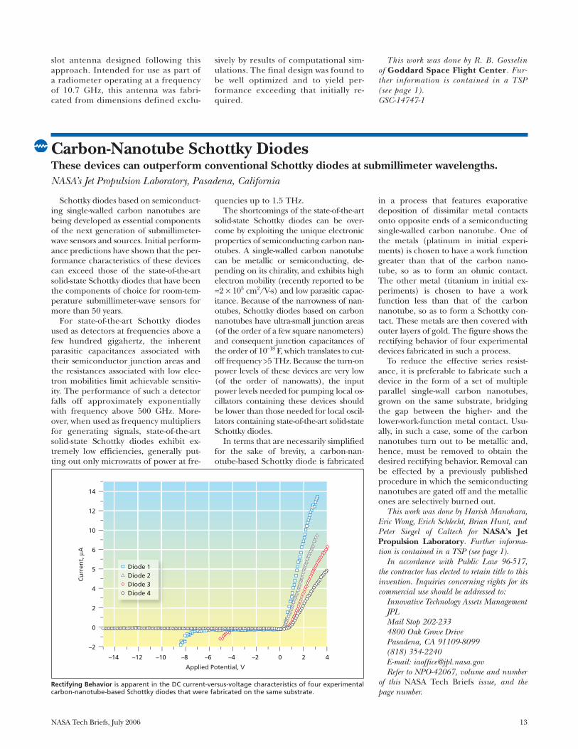
in a process that features evaporativedeposition of dissimilar metal contactsonto opposite ends of a semiconductingsingle-walled carbon nanotube. One ofthe metals (platinum in initial experi-ments) is chosen to have a work functiongreater than that of the carbon nano-tube, so as to form an ohmic contact.The other metal (titanium in initial ex-periments) is chosen to have a workfunction less than that of the carbonnanotube, so as to form a Schottky con-tact. These metals are then covered withouter layers of gold. The figure shows therectifying behavior of four experimentaldevices fabricated in such a process.
To reduce the effective series resist-ance, it is preferable to fabricate such adevice in the form of a set of multipleparallel single-wall carbon nanotubes,grown on the same substrate, bridgingthe gap between the higher- and thelower-work-function metal contact. Usu-ally, in such a case, some of the carbonnanotubes turn out to be metallic and,hence, must be removed to obtain thedesired rectifying behavior. Removal canbe effected by a previously publishedprocedure in which the semiconductingnanotubes are gated off and the metallicones are selectively burned out.
This work was done by Harish Manohara,Eric Wong, Erich Schlecht, Brian Hunt, andPeter Siegel of Caltech for NASA’s JetPropulsion Laboratory. Further informa-tion is contained in a TSP (see page 1).
In accordance with Public Law 96-517,the contractor has elected to retain title to thisinvention. Inquiries concerning rights for itscommercial use should be addressed to:
Innovative Technology Assets ManagementJPLMail Stop 202-2334800 Oak Grove DrivePasadena, CA 91109-8099(818) 354-2240E-mail: [email protected] to NPO-42067, volume and number
of this NASA Tech Briefs issue, and thepage number.
Rectifying Behavior is apparent in the DC current-versus-voltage characteristics of four experimentalcarbon-nanotube-based Schottky diodes that were fabricated on the same substrate.
–14 –12 –10 –8 –6
Applied Potential, V
Cu
rren
t,µA
–4 –2
–2
0
2
4
5
6
10
12
14
0 2 4
Diode 1 Diode 2 Diode 3 Diode 4
NPO-42067ABPI
6

14 NASA Tech Briefs, July 2006
A document discusses an architectureof a spaceborne laser communication sys-tem that provides for a simplified controlsubsystem that stabilizes the line of sightin a desired direction. Heretofore, a typi-cal design for a spaceborne laser commu-nication system has called for a high-bandwidth control loop, a steering mirrorand associated optics, and a fast steering-mirror actuator to stabilize the line ofsight in the presence of vibrations. In thepresent architecture, the need for this fast
steering-mirror subsystem is eliminated bymounting the laser-communication opticson a disturbance-free platform (DFP) thatsuppresses coupling of vibrations to theoptics by ≥60 dB. Taking advantage of mi-crogravitation, in the DFP, the optical as-sembly is free-flying relative to the rest ofthe spacecraft, and a low-spring-constantpointing control subsystem exerts smallforces to regulate the position and orien-tation of the optics via voice coils. Allsteering is effected via the DFP, which can
be controlled in all six degrees of freedomrelative to the spacecraft. A second con-trol loop, closed around a position sensorand the spacecraft attitude-control sys-tem, moves the spacecraft as needed toprevent mechanical contact with the opti-cal assembly.
This work was done by Chien-Chung Chenand Hamid Hemmati of Caltech for NASA’sJet Propulsion Laboratory. Further informa-tion is contained in a TSP (see page 1).NPO-42693
Simplified Optics and Controls for Laser CommunicationsNASA’s Jet Propulsion Laboratory, Pasadena, California
Coherent Detection of High-Rate Optical PPM SignalsQuantum-limited performance is achievable.NASA’s Jet Propulsion Laboratory, Pasadena, California
A method of coherent detection of high-rate pulse-position modulation (PPM) ona received laser beam has been conceivedas a means of reducing the deleterious ef-fects of noise and atmospheric turbulencein free-space optical communication usingfocal-plane detector array technologies. Incomparison with a receiver based on directdetection of the intensity modulation of aPPM signal, a receiver based on the presentmethod of coherent detection performswell at much higher background levels.
In principle, the coherent-detectionreceiver can exhibit quantum-limitedperformance despite atmospheric tur-
bulence. The key components of such areceiver include standard receiver op-tics, a laser that serves as a local oscilla-tor, a focal-plane array of photodetec-tors, and a signal-processing anddata-acquisition assembly needed tosample the focal-plane fields and recon-struct the pulsed signal prior to detec-tion. The received PPM-modulated laserbeam and the local-oscillator beam arefocused onto the photodetector array,where they are mixed in the detectionprocess. The two lasers are of the sameor nearly the same frequency. If the twolasers are of different frequencies, then
the coherent detection process is char-acterized as heterodyne and, using tradi-tional heterodyne-detection terminol-ogy, the difference between the two laserfrequencies is denoted the intermediatefrequency (IF). If the two laser beamsare of the same frequency and remainaligned in phase, then the coherent de-tection process is characterized as homo-dyne (essentially, heterodyne detectionat zero IF).
As a result of the inherent squaringoperation of each photodetector, theoutput current includes an IF compo-nent that contains the signal modula-tion. The amplitude of the IF compo-nent is proportional to the product ofthe local-oscillator signal amplitude andthe PPM signal amplitude. Hence, byusing a sufficiently strong local-oscillatorsignal, one can make the PPM-modu-lated IF signal strong enough to over-come thermal noise in the receiver cir-cuits: this is what makes it possible toachieve near-quantum-limited detectionin the presence of strong background.
Following quantum-limited coherentdetection, the outputs of the individualphotodetectors are automaticallyaligned in phase by use of one or moreadaptive array compensation algorithms[e.g., the least-mean-square (LMS) algo-rithm]. Then the outputs are combinedand the resulting signal is processed toextract the high-rate information, asthough the PPM signal were received bya single photodetector.
In a continuing series of experiments
NPO-40974 Fig 1ABPI
11-3-05 ca
Figure 1. A Coherent Optical Receiver as it is set up for experiments at NASA’s Jet Propulsion Laboratory.

NASA Tech Briefs, July 2006 15
to test this method (see Fig. 1), the localoscillator has a wavelength of 1,064 nm,and another laser is used as a signaltransmitter at a slightly different wave-length to establish an IF of about 6MHz. There are 16 photodetectors in a4×4 focal-plane array; the detector out-puts are digitized at a sampling rate of25 MHz, and the signals in digital formare combined by use of the LMS algo-rithm. Convergence of the adaptivecombining algorithm in the presence of
simulated atmospheric turbulence foroptical PPM signals has already beendemonstrated in the laboratory; thecombined output is shown in Fig. 2(a),and Fig. 2(b) shows the behavior of thephase of the combining weights as afunction of time (or samples). We ob-serve that the phase of the weights has asawtooth shape due to the continuouslychanging phase in the down-convertedoutput, which is not exactly at zero fre-quency.
Detailed performance analysis of thiscoherent free-space optical communica-tion system in the presence of simulatedatmospheric turbulence is currentlyunder way.
This work was done by Victor Vilnrotterand Michela Muñoz Fernández of Caltech forNASA’s Jet Propulsion Laboratory. Fur-ther information is contained in a TSP (seepage 1).NPO-40974
An electronic signal-processing systemdetermines the phases of input signals ar-riving in multiple channels, relative to thephase of a reference signal with which theinput signals are known to be coherent inboth phase and frequency. The system alsogives an estimate of the power levels of theinput signals. A prototype of the systemhas four input channels that handle sig-nals at a frequency of ≈9.5 MHz, but thebasic principles of design and operationare extensible to other signal frequenciesand greater numbers of channels.
The prototype system consists mostlyof three parts:• An analog-to-digital-converter (ADC)
board, which coherently digitizes theinput signals in synchronism with thereference signal and performs somesimple processing;
• A digital signal processor (DSP) in theform of a field-programmable gate
array (FPGA) board, which performsmost of the phase- and power-measure-ment computations on the digital sam-ples generated by the ADC board; and
• A carrier board, which allows a per-sonal computer to retrieve the phaseand power data.The DSP contains four independent
phase-only tracking loops, each of whichtracks the phase of one of the pre-processed input signals relative to that ofthe reference signal (see figure). Thephase values computed by these loopsare averaged over intervals, the length ofwhich is chosen to obtain output fromthe DSP at a desired rate. In addition, asimple sum of squares is computed foreach channel as an estimate of thepower of the signal in that channel.
The relative phases and the powerlevel estimates computed by the DSPcould be used for diverse purposes in
different settings. For example, if theinput signals come from different ele-ments of a phased-array antenna, thephases could be used as indications ofthe direction of arrival of a receivedsignal and/or as feedback for elec-tronic or mechanical beam steering.The power levels could be used asfeedback for automatic gain control inpreprocessing of incoming signals.For another example, the systemcould be used to measure the phasesand power levels of outputs of multi-ple power amplifiers to enable adjust-ment of the amplifiers for optimalpower combining.
This work was done by Samuel Li, JamesLux, Robert McMaster, and Amy Boas ofCaltech for NASA’s Jet Propulsion Lab-oratory. Further information is containedin a TSP (see page 1).NPO-42697
Multichannel Phase and Power DetectorPurposes served by this system include beam steering and power combining.NASA’s Jet Propulsion Laboratory, Pasadena, California
A Functional Block Diagram of the DSP shows one channel. The other channels are identical.
Phase-Shift-Locked Loop Operating at 1/4 of
Sampling Frequency
Squarer
Sum-and-DumpUnit
Sum-and-DumpUnit
Digital Samplesof Input Signal
Raw Phase Values
Multiplier(Imposes Reverse Loop
Gain and Averaging Factors)
Output PowerEstimate
Output Phase
NPO42697 ABPI
12-13-05 bs

NASA Tech Briefs, July 2006 17
Software
Using Satellite Data inWeather Forecasting: I
The GOES Product Generation System(GPGS) is a set of computer codes andscripts that enable the assimilation ofreal-time Geostationary Operational En-vironmental Satellite (GOES) data intoregional-weather-forecasting mathemati-cal models. The GPGS can be used to de-rive such geophysical parameters as landsurface temperature, the amount of pre-cipitable water, the degree of cloud cover,the surface albedo, and the amount of in-solation from satellite measurements ofradiant energy emitted by the Earth andits atmosphere. GPGS incorporates a pri-ori information (initial guesses of thermo-dynamic parameters of the atmosphere)and radiometric measurements from thegeostationary operational environmentalsatellites along with mathematical modelsof physical principles that govern thetransfer of energy in the atmosphere.GPGS solves the radiative-transfer equa-tion and provides the resulting data prod-ucts in formats suitable for use byweather-forecasting computer programs.The data-assimilation capability affordedby GPGS offers the potential to improvelocal weather forecasts ranging from 3hours to 2 days — especially with respectto temperature, humidity, cloud cover,and the probability of precipitation. Theimprovements afforded by GPGS couldbe of interest to news media, utility com-panies, and other organizations that uti-lize regional weather forecasts.
This program was written by Gary J.Jedlovec and Ronnie J. Suggs of MarshallSpace Flight Center and Juan M. Lecue ofthe Universities Space Research Associationand the Global Hydrology and Climate Center.For further information, contact Sammy Nabors,MSFC Commercializaton Assistance Lead, [email protected]. Refer to MFS-31615.
Using Dissimilarity Metrics To Identify Interesting Designs
A computer program helps to blendthe power of automated-search software,which is able to generate large numbersof design solutions, with the insight of ex-pert designers, who are able to identifypreferred designs but do not have time toexamine all the solutions. From among
the many automated solutions to a givendesign problem, the program selects asmaller number of solutions that are wor-thy of scrutiny by the experts in the sensethat they are sufficiently dissimilar fromeach other. The program makes the se-lection in an interactive process that in-volves a sequence of data-mining steps in-terspersed with visual displays of results ofthese steps to the experts. At crucialpoints between steps, the experts providedirectives to guide the process. The pro-gram uses heuristic search techniques toidentify nearly optimal design solutionsand uses dissimilarity metrics defined bythe experts to characterize the degree towhich solutions are interestingly differ-ent. The search, data-mining, and visuali-zation features of the program were de-rived from previously developedrisk-management software used to sup-port a risk-centric design methodology.
This program was written by MartinFeather of Caltech and James Kiper of MiamiUniversity, Oxford, Ohio, for NASA’s JetPropulsion Laboratory. Further informa-tion is contained in a TSP (see page 1).
This software is available for commerciallicensing. Please contact Karina Edmonds ofthe California Institute of Technology at(626) 395-2322. Refer to NPO-40456.
X-Windows PVT WidgetClass
The X-Windows Process ValidationTable (PVT) Widget Class (“Class” is usedhere in the object-oriented-programmingsense of the word) was devised to simplifythe task of implementing network regis-tration services for Information SharingProtocol (ISP) graphical-user-interface(GUI) computer programs. Heretofore,ISP PVT programming tasks have re-quired many method calls to identify,query, and interpret the connections andmessages exchanged between a clientand a PVT server. Normally, program-mers have utilized direct access to UNIXsocket libraries to implement the PVTprotocol queries, necessitating the use ofmany lines of source code to perform fre-quent tasks. Now, the X-Windows PVTWidget Class encapsulates ISP clientserver network registration managementtasks within the framework of an X Win-dows widget. Use of the widget frame-work enables an X Windows GUI pro-gram to interact with PVT services in an
abstract way and in the same manner asthat of other graphical widgets, making iteasier to program PVT clients. Wrappingthe PVT services inside the widget frame-work enables a programmer to treat aPVT server interface as though it were aGUI. Moreover, an alternate subclasscould implement another service in awidget of the same type.
This program was written by Matthew R.Barry of United Space Alliance for JohnsonSpace Center. For further information, con-tact the Johnson Technology Transfer Officeat (281) 483-3809.MSC-23582
Shuttle Data Center File-Processing Tool in Java
A Java-language computer programhas been written to facilitate mining ofdata in files in the Shuttle Data Center(SDC) archives. This program can be ex-ecuted on a variety of workstations or viaWeb-browser programs. This program ispartly similar to prior C-language pro-grams used for the same purpose, whilediffering from those programs in that itexploits the platform-neutrality of Javain implementing several features thatare important for analysis of large sets oftime-series data. The program supportsregular expression queries of SDCarchive files, reads the files, interleavesthe time-stamped samples according to achosen output, then transforms the re-sults into that format. A user can chooseamong a variety of output file formatsthat are useful for diverse purposes, in-cluding plotting, Markov modeling,multivariate density estimation, andwavelet multiresolution analysis, as wellas for playback of data in support of sim-ulation and testing.
This program was written by Matthew R.Barry and Walter H. Miller of United SpaceAlliance for Johnson Space Center. Forfurther information, contact the JohnsonTechnology Transfer Office at (281) 483-3809.MSC-23584
Statistical Evaluation of Uti-lization of the ISS
PayLoad Utilization Modeler(PLUM) is a statistical-modeling com-puter program used to evaluate the ef-fectiveness of utilization of the Interna-

18 NASA Tech Briefs, July 2006
tional Space Station (ISS) in terms ofthe number of research facilities thatcan be operated within a specified inter-val of time. PLUM is designed to bal-ance the requirements of research facil-ities aboard the ISS against theresources available on the ISS. PLUMcomprises three parts: an interface forthe entry of data on constraints and onrequired and available resources, a data-base that stores these data as well as the
program output, and a modeler. Themodeler comprises two subparts: onethat generates tens of thousands of ran-dom combinations of research facilitiesand another that calculates the usage ofresources for each of those combina-tions. The results of these calculationsare used to generate graphical and tab-ular reports to determine which facili-ties are most likely to be operable onthe ISS, to identify which ISS resources
are inadequate to satisfy the demandsupon them, and to generate other datauseful in allocation of and planning ofresources.
This program was written by Ross Andrewsand Alida Andrews of Science ApplicationsInternational Corp. for Johnson SpaceCenter. For further information, contact theJohnson Technology Transfer Office at (281)483-3809.MSC-23592

NASA Tech Briefs, July 2006 19
Materials
Aerogels for Thermal Insulation of Thermoelectric DevicesEnergy-conversion efficiencies would be increased and operational lifetimes prolonged.NASA’s Jet Propulsion Laboratory, Pasadena, California
Silica aerogels have been shown to beattractive for use as thermal-insulationmaterials for thermoelectric devices. It isdesirable to thermally insulate the legsof thermoelectric devices to suppress lat-eral heat leaks that degrade thermal effi-ciency. Aerogels offer not only high ther-mal-insulation effectiveness, but also acombination of other properties that areespecially advantageous in thermoelec-tric-device applications.
Aerogels are synthesized by means ofsol-gel chemistry, which is ideal for castinginsulation into place. As the scale of thedevices to be insulated decreases, thecastability from liquid solutions becomesincreasingly advantageous: By virtue ofcastability, aerogel insulation can be madeto encapsulate devices having any sizefrom macroscopic down to nanoscopicand possibly having complex, three-di-mensional shapes. Castable aerogels canpermeate voids having characteristic di-mensions as small as nanometers. Hence,practically all the void space surroundingthe legs of thermoelectric devices could befilled with aerogel insulation, making theinsulation highly effective. Because aero-gels have the lowest densities of any knownsolid materials, they would add very littlemass to the encapsulated devices.
The thermal-conductivity values ofaerogels are among the lowest reportedfor any material, even after taking ac-count of the contributions of convec-tion and radiation (in addition to truethermal conduction) to overall effec-tive thermal conductivities. Even in am-bient air, the contribution of convec-tion to effective overall thermalconductivity of an aerogel is extremelylow because of the highly tortuous na-ture of the flow paths through theporous aerogel structure. For applica-tions that involve operating tempera-tures high enough to give rise to signif-icant amounts of infrared radiation,opacifiers could be added to aerogels toreduce the radiative contributions tooverall effective thermal conductivities.One example of an opacifier is carbonblack, which absorbs infrared radiation.Another example of an opacifier is mi-cron-sized metal flakes, which reflect in-frared radiation.
Encapsulation in cast aerogel insula-tion also can help prolong the opera-tional lifetimes of thermoelectric devicesthat must operate in vacuum and thatcontain SiGe or such advanced skutteru-dite thermoelectric materials as CoSb3
and CeFe3.5Co0.5Sb12. The primary cause
of deterioration of most thermoelectricmaterials is thermal decomposition orsublimation (e.g., sublimation of Sbfrom CoSb3) at typical high operatingtemperatures. Aerogel present near thesurface of CoSb3 can impede the out-ward transport of Sb vapor by establish-ing a highly localized, equilibrium Sb-vapor atmosphere at the surface of theCoSb3.
This work was done by Jeffrey Sakamoto,Jean-Pierre Fleurial, Jeffrey Snyder, StevenJones, and Thierry Caillat of Caltech forNASA’s Jet Propulsion Laboratory. Fur-ther information is contained in a TSP (seepage 1).
In accordance with Public Law 96-517,the contractor has elected to retain title to thisinvention. Inquiries concerning rights for itscommercial use should be addressed to
Innovative Technology Assets ManagementJPLMail Stop 202-2334800 Oak Grove DrivePasadena, CA 91109-8099(818) 354-2240E-mail: [email protected] to NPO-40630, volume and number
of this NASA Tech Briefs issue, and thepage number.
Nanotube Dispersions Made With Charged SurfactantLyndon B. Johnson Space Center, Houston, Texas
Dispersions (including monodisper-sions) of nanotubes in water at relativelyhigh concentrations have been formu-lated as prototypes of reagents for use inmaking fibers, films, and membranesbased on single-walled carbon nanotubes(SWNTs). Other than water, the ingredi-ents of a dispersion of this type includeone or more charged surfactant(s) andcarbon nanotubes derived from theHiPco™ (or equivalent) process. Amongreagents known to be made fromHiPco™ (or equivalent) SWNTs, theseare the most concentrated and are ex-
pected to be usable in processing of bulkstructures and materials. Test data indi-cate that small bundles of SWNTs and sin-gle SWNTs at concentrations up to 1.1weight percent have been present inwater plus surfactant. This developmentis expected to contribute to the growth ofan industry based on applied carbon nan-otechnology. There are expected to becommercial applications in aerospace,avionics, sporting goods, automotiveproducts, biotechnology, and medicine.
This work was done by Cynthia Kuper andMike Kuzma of Versilant Nanotechnologies for
Johnson Space Center. For further informa-tion, contact the Technology Transfer Office at(281) 483-3809.
In accordance with Public Law 96-517,the contractor has elected to retain title to thisinvention. Inquiries concerning rights for itscommercial use should be addressed to:
Versilant Nanotechnologies3231 Walnut St.Philadelphia, PA 19104Refer to MSC-23383, volume and number
of this NASA Tech Briefs issue, and thepage number.

20 NASA Tech Briefs, July 2006
Several recently formulated nickel-base superalloys have been developedwith excellent high-temperature creepresistance, at lower densities than thoseof currently used nickel-base superal-loys. These alloys are the latest prod-ucts of a continuing effort to developalloys that have even greater strength-
to-weight ratios, suitable for use in tur-bine blades of aircraft engines. Massdensities of turbine blades exert a sig-nificant effect on the overall weight ofaircraft. For a given aircraft, a reduc-tion in the density of turbine blades en-ables design reductions in the weightof other parts throughout the turbine
rotor, including the disk, hub, andshaft, as well as supporting structuresin the engine. The resulting total re-duction in weight can be 8 to 10 timesthat of the reduction in weight of theturbine blades.
The approach followed in formulat-ing these alloys involved several strate-gies for identifying key alloying elementsand the range of concentration of eachelement to study. To minimize the num-ber of alloys needed to be cast, a design-of-experiments methodology wasadopted. A statistics-based computerprogram that models the effects of vary-ing compositions of four elements, in-cluding effects of two-way interactionsbetween elements, was used to test allpossible alloys within the design space.The starting points for the computa-tional analysis were three alloy composi-tions mandated by engineering consen-sus. After likewise identification of keyalloying elements to vary and the al-lowed ranges of concentrations, thecomputer program then selects a mini-mum number of alloys within the designspace to allow determination of effectsfor all four elements and their interac-tions.
On the basis of the results of the com-putational analysis, thirteen alloys werecast for determination of density and mi-crostructural stability. Of these alloys,eight were cast into larger heats of singlecrystals and subjected to creep rupturetests at temperatures of 1,800 and 2,000°F (982 and 1,093 °C, respectively). Asshown in Figure 1, the densities of thethree strongest alloys based on creeprupture were significantly lower than thedensity of the best second-, third-, andfourth-generation superalloys currentlyin use. As seen in Figure 2, the creepstrength as a function of density forthese various low-density superalloys wasfound to exceed those of the current su-peralloys.
In a departure from previous alloy-design practices, a conscious decisionwas made to sacrifice some resistance tooxidation for the sake of further opti-mization with respect to density andstrength. This strategy involves relianceon a robust coating system for resist-ance to oxidation. The widespread useof coated turbine blades in engines formore than 40 years indicates this is a
Ren
eN
5
PWA
1484
Ren
eN
6
CM
SX-1
0
EPM
-102
LDS-
1101
LDS-
5555
LDS-
5051
Previously DevelopedSuperalloys
Low-DensitySuperalloys
0.335
0.330
0.325
0.320
0.315
0.310
0.305
0.300
Den
sity
,lb
/in.3
LEW-17672-1 Fig 1ABPI
11-7-05 bs
Low-Density, Creep-Resistant Single-Crystal Superalloys Weights of aircraft turbine rotors could be reduced significantly. John H. Glenn Research Center, Cleveland, Ohio
Figure 1. Measured Densities of Low-Density Superalloys are compared to previously developed superalloys.
0.28 0.3 0.32 0.34
Alloy Density, lb/in.3
0
20
40
60
80
Cre
epSt
ren
gth
,ksi
1800
°F,1
00h
Goal
N4N5
PWA1484
N6CMSX-10
EPM102
LEW-17672-1 Fig 2ABPI
5
Figure 2. Past Development Approaches for first generation (Rene N4), second generation (Rene N5and PWA1484), third generation (Rene N6 and CMSX-10), and fourth generation (EPM 102) superalloysincreased alloy density with creep strength through the use of dense refractory element additions.The NASA GRC goal was to increase creep strength without concurrent increases in alloy density.

NASA Tech Briefs, July 2006 21
quite reasonable strategy. Nevertheless,these low-density superalloys werefound to be as oxidation-resistant asthat of first-generation-superalloy sin-gle crystals. Further optimization withrespect to density and strength can beachieved if resistance to oxidation is
further sacrificed to an acceptable ex-tent.
This work was done by Rebecca A.MacKay, Timothy P. Gabb, James L. Smialek,and Michael V. Nathal of Glenn ResearchCenter. Further information is contained ina TSP (see page 1).
Inquiries concerning rights for the commer-cial use of this invention should be addressedto NASA Glenn Research Center, InnovativePartnerships Office, Attn: Steve Fedor, MailStop 4–8, 21000 Brookpark Road, Cleveland,Ohio 44135. Refer to LEW-17672-1

NASA Tech Briefs, July 2006 23
Mechanics
Excitations for Rapidly Estimating Flight-Control ParametersParameters are estimated, in nearly real time, from responses to these excitations.Dryden Flight Research Center, Edwards, California
A flight test on an F-15 airplane wasperformed to evaluate the utility of pre-scribed simultaneous independent sur-face excitations (PreSISE) for real-timeestimation of flight-control parameters,including stability and control deriva-
tives. The ability to extract these deriva-tives in nearly real time is needed tosupport flight demonstration of intelli-gent flight-control system (IFCS) con-cepts under development at NASA, inacademia, and in industry. Tradition-
ally, flight maneuvers have been de-signed and executed to obtain esti-mates of stability and control deriva-tives by use of a post-flight analysistechnique. For an IFCS, it is required tobe able to modify control laws in real
time for an aircraft that has beendamaged in flight (because of com-bat, weather, or a system failure).
The flight test included PreSISE ma-neuvers, during which all desired con-trol surfaces are excited simultaneously,but at different frequencies, resulting inaircraft motions about all coordinateaxes. The objectives of the test were toobtain data for post-flight analysis andto perform the analysis to determine:• The accuracy of derivatives esti-
mated by use of PreSISE,• The required durations of PreSISE
inputs, and• The minimum required magnitudes
of PreSISE inputs.The PreSISE inputs in the flight
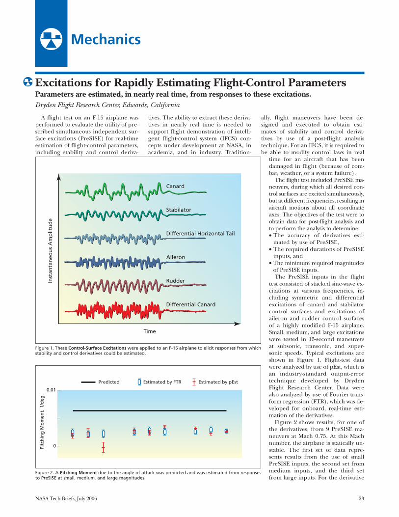
test consisted of stacked sine-wave ex-citations at various frequencies, in-cluding symmetric and differentialexcitations of canard and stabilatorcontrol surfaces and excitations ofaileron and rudder control surfacesof a highly modified F-15 airplane.Small, medium, and large excitationswere tested in 15-second maneuversat subsonic, transonic, and super-sonic speeds. Typical excitations areshown in Figure 1. Flight-test datawere analyzed by use of pEst, which isan industry-standard output-errortechnique developed by DrydenFlight Research Center. Data werealso analyzed by use of Fourier-trans-form regression (FTR), which was de-veloped for onboard, real-time esti-mation of the derivatives.
Figure 2 shows results, for one ofthe derivatives, from 9 PreSISE ma-neuvers at Mach 0.75. At this Machnumber, the airplane is statically un-stable. The first set of data repre-sents results from the use of smallPreSISE inputs, the second set frommedium inputs, and the third setfrom large inputs. For the derivative
Canard
Stabilator
Differential Horizontal Tail
Aileron
Rudder
Differential Canard
Time
Inst
anta
neo
us
Am
plit
ud
e
DRC-03-06 Fig 1ABPI
7-29-04 bs
0.01
Pitc
hin
gM
om
ent,
1/d
eg.
0
Predicted Estimated by FTR Estimated by pEst
DRC-03-06 Fig 2ABPI
7-29-04 bs
Figure 1. These Control-Surface Excitations were applied to an F-15 airplane to elicit responses from whichstability and control derivatives could be estimated.
Figure 2. A Pitching Moment due to the angle of attack was predicted and was estimated from responsesto PreSISE at small, medium, and large magnitudes.

24 NASA Tech Briefs, July 2006
in question, the estimate was the same,independent of input size or analysistechnique. Typically, the longitudinalderivatives were estimated with accept-ably high accuracy and, using FTR, con-verged to final values after about 5 sec-onds of inputs. Some lateral-directional
derivatives were not estimated as accu-rately, because signal-to-noise ratioswere low. Efforts to optimize the inputsfor increased accuracy in estimation ofthe derivatives are underway.
This work was done by Tim Moes andMark Smith of Dryden Flight Research
Center and Gene Morelli of Langley Re-search Center. For further information, con-tact Mr. Moes at (661) 276-3054, Mr.Smith at (661) 276-3177, or Mr. Morelli at(757) 864-4078.DRC-03-06
A technique for real-time estimation ofstability and control derivatives (deriva-tives of moment coefficients with respectto control-surface deflection angles) wasused to support a flight demonstration ofa concept of an indirect-adaptive intelli-gent flight control system (IFCS). Tradi-tionally, parameter identification, includ-ing estimation of stability and controlderivatives, is done post-flight. However,for the indirect-adaptive IFCS concept,parameter identification is required dur-ing flight so that the system can modifycontrol laws for a damaged aircraft.
The flight demonstration was carriedout on a highly modified F-15 airplane(see Figure 1). The main objective was toestimate the stability and control deriva-tives of the airplane in nearly real time. Asecondary goal was to develop a system toautomatically assess the quality of the re-sults, so as to be able to tell a learningneural network which data to use.
Parameter estimation was performedby use of Fourier-transform regression(FTR) — a technique developed at NASALangley Research Center. FTR is an equa-tion-error technique that operates in thefrequency domain. Data are put into thefrequency domain by use of a recursiveFourier transform for a discrete fre-quency set. This calculation simplifiesmany subsequent calculations, removesbiases, and automatically filters out databeyond the chosen frequency range.
FTR as applied here was tailored towork with pilot inputs, which produce
correlated surface positions that preventaccurate parameter estimates, by replac-ing half the derivatives with predictedvalues. FTR was also set up to work onlyon a recent window of data, to accom-modate changes in flight condition.
A system of confidence measures wasdeveloped to identify quality-parameterestimates that a learning neural networkcould use. This system judged the esti-mates primarily on the basis of their esti-mated variances and of the level of air-craft response.
The resulting FTR system was imple-mented in the Simulink software systemand autocoded in the C programming lan-guage for use on the Airborne ResearchTest System (ARTS II) computer installedin the F-15 airplane. The Simulink modelwas also used in a control room that uti-lizes the Ring Buffered Network Bus hard-ware and software, making it possible toevaluate test points during flights.
In-flight parameter estimation was donefor piloted and automated maneuvers, pri-
marily at three test conditions. Figure 2shows results for pitching moment due tosymmetric stabilator actuations for a seriesof three pitch doublet maneuvers (in adoublet maneuver, a command to changeattitude in a given direction by a givenamount is followed immediately by a com-mand to change attitude in the oppositedirection by the same amount). A timewindow of 5 seconds was used. The por-tions of the curves shown in red are thosethat passed the confidence tests.
The technique showed good conver-gence for most derivatives for both kindsof maneuvers — typically within a fewseconds. The confidence tests were mar-ginally successful, and it would be neces-sary to refine them for use in an IFCS.
This work was done by Mark Smith and TimMoes of Dryden Flight Research Centerand Gene Morelli of Langley Research Center.For further information, contact Mark Smith at(661) 276-3177, Tim Moes at (661) 276-3054, or Gene Morelli at (757) 864-4078.DRC-03-05
Estimation of Stability and Control Derivatives of an F-15Parameters can be estimated in nearly real time for use in adaptive flight control.Dryden Flight Research Center, Edwards, California
Figure 1. The F-15 #837 Airplane was used in aflight demonstration of the real-time parame-ter-estimation technique.
2
1
0
–1
–2
–0.006
–0.008
–0.010
–0.012
–0.0140 5 10 15 20
Time, Seconds
25 30 35 40
Pitc
hC
on
tro
lD
eriv
ativ
e,1/
deg
.Lo
ng
itu
din
alSt
ick
Inp
ut,
in.
Real-Time EstimateEstimate Generated by Linearized Aerodynamic ModelReal-Time EstimateEstimate Generated by Linearized Aerodynamic Model
DRC-03-05 fig 2ABPI
7
Figure 2. These Results Derived From a Pitching-Moment Test involving three pitch-doublet maneu-vers illustrate the capability afforded by the real-time parameter-estimation technique.

NASA Tech Briefs, July 2006 25
A tool makes it possible to couple atorque wrench to an externally knurled,internally threaded, round cable connec-tor. The purpose served by the tool is tofacilitate the tightening of multiple suchconnectors (or the repeated tighteningof the same connector) to repeatabletorques.
The design of a prior cable-connec-tor/torque-wrench coupling tool pro-vided for application of the torque-wrench jaws to a location laterallyoffset from the axis of rotation of thecable connector, making it necessary tocorrect the torque reading for the off-set. Unlike the design of the prior tool,the design of the present tool providesfor application of the torque-wrenchjaws to a location on the axis of rota-tion, obviating correction of the torquereading for offset.
The present tool (see figure)consists of a split collet containing aslot that provides clearance for insert-ing and bending the cable, a collet-
locking sleeve, a collet-locking nut,and a torque-wrench adaptor that ispress-fit onto the collet. Once the col-let is positioned on the cable connec-tor, the collet-locking nut is turned toforce the collet-locking sleeve over thecollet, compressing the collet throughengagement of tapered surfaces onthe outside of the collet and the insideof the locking sleeve. Because the col-let is split and therefore somewhatflexible, this compression forces thecollet inward to grip the connector se-curely. The torque wrench is then ap-plied to the torque-wrench adaptor inthe usual manner for torquing a nutor a bolt.
This was done by Scott C. Hacker,Richard J. Dean, and Scott W. Burge ofJohnson Space Center. For further infor-mation, contact Johnson Technology TransferOffice at (281) 483-3809.
Tool for Coupling a Torque Wrench to a Round Cable ConnectorTorque is applied without offset.Lyndon B. Johnson Space Center, Houston, Texas
Torque-WrenchAdaptor
Axis
Collet-LockingNut
Collet-LockingSleeve
MSC-23695ABPI
9-22-04 bs
This Simple Tool makes it possible to tightenround cable connectors to repeatable torques,without need to make offset corrections.


NASA Tech Briefs, July 2006 27
Machinery/Automation
Ultrasonically Actuated Tools for Abrading Rock SurfacesThese offer the same advantages as do ultrasonically actuated drilling and coring tools.NASA’s Jet Propulsion Laboratory, Pasadena, California
An ultrasonic rock-abrasion tool(URAT) was developed using the sameprinciple of ultrasonic/sonic actuationas that of the tools described in two priorNASA Tech Briefs articles: “Ultra-sonic/Sonic Drill/Corers With Inte-grated Sensors (NPO-20856), Vol. 25,No. 1 (January 2001), page 38 and “Ul-trasonic/Sonic Mechanisms for Drillingand Coring” (NPO-30291), Vol. 27, No.9 (September 2003), page 65. Hence,like those tools, the URAT offers thesame advantages of low power demand,mechanical simplicity, compactness, andability to function with very small axialloading (very small contact force be-tween tool and rock).
Like a tool described in the second ofthe cited previous articles, a URAT in-cludes (1) a drive mechanism that com-prises a piezoelectric ultrasonic actuator,an amplification horn, and a mass that isfree to move axially over a limited rangeand (2) an abrasion tool bit. A URAT toolbit is a disk that has been machined or oth-erwise formed to have a large number ofteeth and an overall shape chosen to im-part the desired shape (which could beflat or curved) to the rock surface to beabraded. In operation, the disk and thusthe teeth are vibrated in contact with therock surface. The concentrated stresses atthe tips of the impinging teeth repeatedlyinduce microfractures and thereby abradethe rock. The motion of the tool inducesan ultrasonic transport effect that dis-places the cuttings from the abraded area.
The figure shows a prototype URAT. Apiezoelectric-stack/horn actuator is housed
in a cylindrical container. The movementof the actuator and bit with respect to thehousing is aided by use of mechanical slid-ers. A set of springs accommodates the mo-tion of the actuator and bit into or out ofthe housing through an axial range be-tween 5 and 7 mm. The springs impose anapproximately constant force of contact be-tween the tool bit and the rock to beabraded. A dust shield surrounds the bit,serving as a barrier to reduce the migrationof rock debris to sensitive instrumentationor mechanisms in the vicinity. A bushing at
the tool-bit end of the housing reduces theflow of dust into the actuator and retainsthe bit when no axial load is applied.
This work was done by Benjamin Dolgin,Stewart Sherrit, Yoseph Bar-Cohen, RichardRainen, Steve Askin, Donald Bickler, DonaldLewis, John Carson, Stephen Dawson, XiaoqiBao, and Zensheu Chang of Caltech andThomas Peterson of Cybersonics for NASA’s JetPropulsion Laboratory. Further informationis contained in a TSP (see page 1).NPO-30403
This Prototype URAT is one of several that have been constructed thus far. It has a total mass of 0.4kg, a length of 5.65 in. (14.4 cm), and a maximum diameter of 2.5 in. (6.35 cm). The textured disk atthe right end is the tool bit.
NPO-30403ABPI
3-27-06 ca
Active Struts With Variable Spring Stiffness and DampingThese struts would act as linear actuators and controllable shock absorbers.Langley Research Center, Hampton, Virginia
Controllable active struts that wouldfunction as linear actuators with variablespring stiffness and damping have beenproposed as components of advancedsuspension systems of future wheeled
ground vehicles. The contemplated ad-vanced suspension systems would in-clude computer-based control subsys-tems that would continually adjust theactuator responses to obtain optimal
combinations of safety and comfortunder operating conditions rangingfrom low speeds over smooth roads tohigh speeds over rough, unpavedground. The proposed struts and suspen-

28 NASA Tech Briefs, July 2006
sion systems were originally intended foruse in military vehicles, but there couldalso be a broad commercial market forthem in trucks and sport utility vehicles.
A strut according to the proposal (seefigure) would include an air spring inthe form of a plunger sliding longitu-dinally in a pneumatic chamber. Com-pressed air would be supplied to thepneumatic chamber, from an externalpump and accumulator, via a pneumatichose and a high-speed valve. The cham-ber would be instrumented with (1) anelectronic extensometer to monitor theaxial displacement of the plunger and(2) an electronic air-pressure sensor.Notwithstanding the extensometer, theair spring would be used primarily to reg-ulate the spring stiffness, rather than thelength, of the strut. The diameter of theplunger would be small, so that only asmall amount of compressed air wouldhave to be pumped in or allowed to flowout to change the spring stiffness by agiven amount. Because of the smallamount of air needed and because theair spring would operate at moderate tohigh pressure, the required amount ofair could be made to flow into or out ofit rapidly and, hence, the spring stiffnesscould be changed rapidly on command.
The pneumatic chamber would alsoserve as a plunger that would slide longi-tudinally in a hydraulic chamber. Likethe pneumatic chamber, the hydraulicchamber would be equipped with a pres-sure sensor, extensometer, and high-speed valve. However, instead of com-pressed air, hydraulic fluid would besupplied to this chamber from an exter-nal hydraulic pump, accumulator, andreservoir. The hydraulic chamber wouldbe used primarily to adjust the length ofthe strut; secondarily, it could be used asa very stiff spring in the event of a mal-function of the air spring. The hydraulicfluid would be pumped in to extend thestrut. Retraction would be effected by ac-tuating the valve to allow the load on thestrut to push hydraulic fluid back to thereservoir. Like the pneumatic chamber,
the hydraulic chamber would have asmall volume and would be operated athigh pressure; hence, the length of thestrut could be adjusted within a short re-sponse time.
A device denoted an actuator-restrain-ing device (ARD) would provide control-lable damping. The ARD would include(1) a set of plates, oriented in radial-axialplanes, that would move with one end ofthe strut and (2) a set of pairs of plates,each pair parallel and close to one of thefirst-mentioned plates, that would movewith the other end of the strut. The nar-row spaces between the plates would befilled with a magnetorheological fluid,the effective viscosity of which would becontrolled by the current in an electro-magnet coil. In the absence of current,the plates would slide almost freely, so
that any damping would be that attribut-able to friction damping in the air springand the hydraulic actuator. In general,the amount of damping could be in-creased or decreased to almost any de-sired level by increasing or decreasing thecurrent applied to the coil. By applyingsufficient current, one could even obtaina damping or restraining force greaterthan the weight of the vehicle. The re-sponse time of the ARD would be anorder of magnitude shorter than the re-sponse times of the pneumatic and hy-draulic actuators.
This work was done by Gary L. Farley ofthe U. S. Army Research Laboratory for Lan-gley Research Center. Further informa-tion is contained in a TSP (see page 1).LAR-16355-1
Plunger
PneumaticChamber
HydraulicChamber
Port for Air
Port forHydraulic
Fluid
ElectromagnetCoil
Outer Wall
Seal
Plates ThatMove With the
Upper End
Plates ThatMove With the
Lower End
LAR-16355-1ABPI
5-8-03 es
A Strut Assembly according to the proposal would contain a pneumatic actuator, a hydraulic actuator,and a magnetorheological damping actuator.
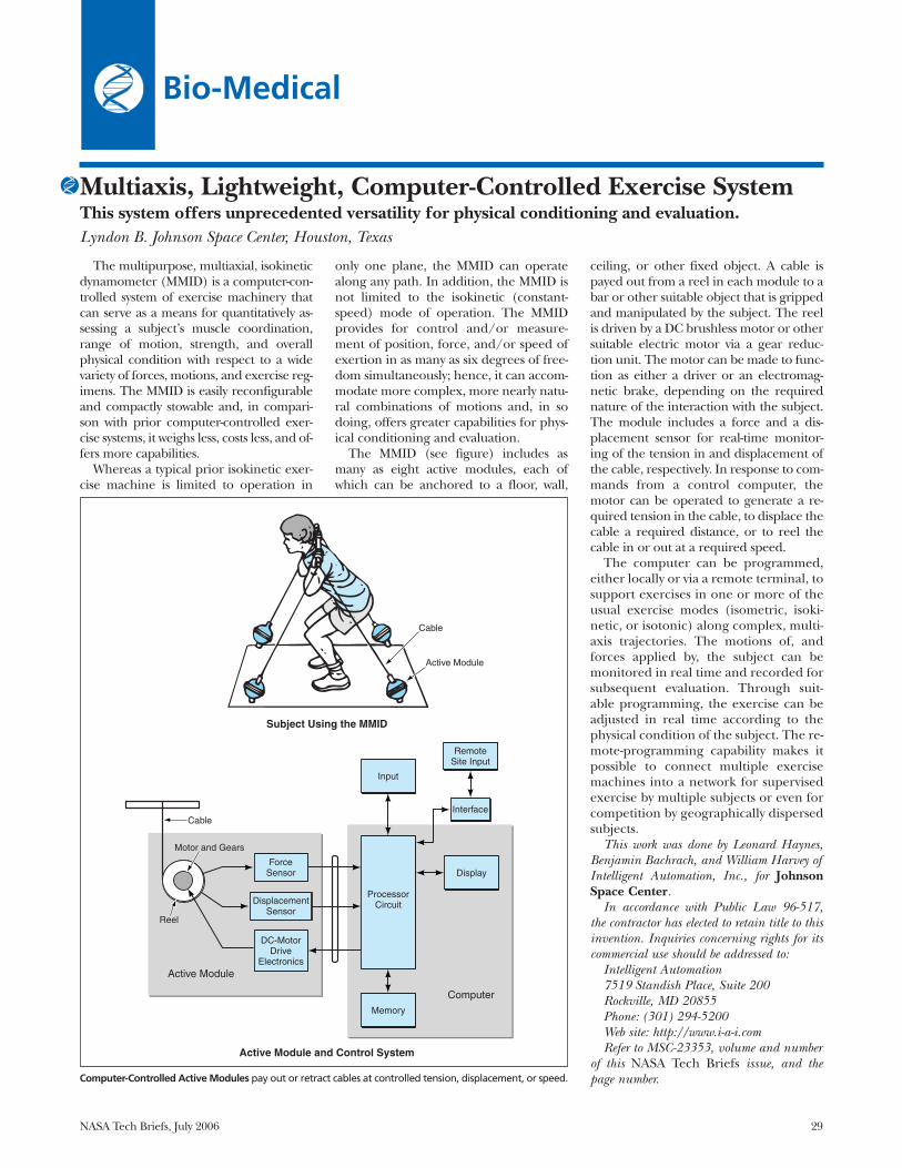
NASA Tech Briefs, July 2006 29
Multiaxis, Lightweight, Computer-Controlled Exercise SystemThis system offers unprecedented versatility for physical conditioning and evaluation.Lyndon B. Johnson Space Center, Houston, Texas
The multipurpose, multiaxial, isokineticdynamometer (MMID) is a computer-con-trolled system of exercise machinery thatcan serve as a means for quantitatively as-sessing a subject’s muscle coordination,range of motion, strength, and overallphysical condition with respect to a widevariety of forces, motions, and exercise reg-imens. The MMID is easily reconfigurableand compactly stowable and, in compari-son with prior computer-controlled exer-cise systems, it weighs less, costs less, and of-fers more capabilities.
Whereas a typical prior isokinetic exer-cise machine is limited to operation in
only one plane, the MMID can operatealong any path. In addition, the MMID isnot limited to the isokinetic (constant-speed) mode of operation. The MMIDprovides for control and/or measure-ment of position, force, and/or speed ofexertion in as many as six degrees of free-dom simultaneously; hence, it can accom-modate more complex, more nearly natu-ral combinations of motions and, in sodoing, offers greater capabilities for phys-ical conditioning and evaluation.
The MMID (see figure) includes asmany as eight active modules, each ofwhich can be anchored to a floor, wall,
ceiling, or other fixed object. A cable ispayed out from a reel in each module to abar or other suitable object that is grippedand manipulated by the subject. The reelis driven by a DC brushless motor or othersuitable electric motor via a gear reduc-tion unit. The motor can be made to func-tion as either a driver or an electromag-netic brake, depending on the requirednature of the interaction with the subject.The module includes a force and a dis-placement sensor for real-time monitor-ing of the tension in and displacement ofthe cable, respectively. In response to com-mands from a control computer, themotor can be operated to generate a re-quired tension in the cable, to displace thecable a required distance, or to reel thecable in or out at a required speed.
The computer can be programmed,either locally or via a remote terminal, tosupport exercises in one or more of theusual exercise modes (isometric, isoki-netic, or isotonic) along complex, multi-axis trajectories. The motions of, andforces applied by, the subject can bemonitored in real time and recorded forsubsequent evaluation. Through suit-able programming, the exercise can beadjusted in real time according to thephysical condition of the subject. The re-mote-programming capability makes itpossible to connect multiple exercisemachines into a network for supervisedexercise by multiple subjects or even forcompetition by geographically dispersedsubjects.
This work was done by Leonard Haynes,Benjamin Bachrach, and William Harvey ofIntelligent Automation, Inc., for JohnsonSpace Center.
In accordance with Public Law 96-517,the contractor has elected to retain title to thisinvention. Inquiries concerning rights for itscommercial use should be addressed to:
Intelligent Automation 7519 Standish Place, Suite 200Rockville, MD 20855Phone: (301) 294-5200Web site: http://www.i-a-i.com Refer to MSC-23353, volume and number
of this NASA Tech Briefs issue, and thepage number.
Bio-Medical
Computer-Controlled Active Modules pay out or retract cables at controlled tension, displacement, or speed.
Cable
Active Module
Input
Display
Memory
ProcessorCircuit
RemoteSite Input
ForceSensor
Motor and Gears
Reel
DC-MotorDrive
Electronics
DisplacementSensor
Interface
Computer
Active Module
Cable
Subject Using the MMID
Active Module and Control System

30 NASA Tech Briefs, July 2006
Dehydrating and Sterilizing Wastes Using Supercritical CO2Lyndon B. Johnson Space Center, Houston, Texas
A relatively low-temperature process fordehydrating and sterilizing biohazardouswastes in an enclosed life-support system ex-ploits (1) the superior mass-transport prop-erties of supercritical fluids in general and(2) the demonstrated sterilizing propertyof supercritical CO2 in particular. Thewastes to be treated are placed in a cham-ber. Liquid CO2, drawn from storage at apressure of 850 psi (≈5.9 MPa) and temper-
ature of 0 °C, is compressed to pressure of2 kpsi (≈14 MPa) and made to flow into thechamber. The compression raises the tem-perature to 10 °C. The chamber and itscontents are then further heated to 40 °C,putting the CO2 into a supercritical state, inwhich it kills microorganisms in the cham-ber. Carrying dissolved water, the CO2
leaves the chamber through a back-pres-sure regulator, through which it is ex-
panded back to the storage pressure. Theexpanded CO2 is refrigerated to extract thedissolved water as ice, and is then returnedto the storage tank at 0 °C.
This work was done by Ian J. Brown of Lyn-ntech, Inc. for Johnson Space Center. Forfurther information, contact the Johnson Tech-nology Transfer Office at (281) 483-3809.MSC-23495
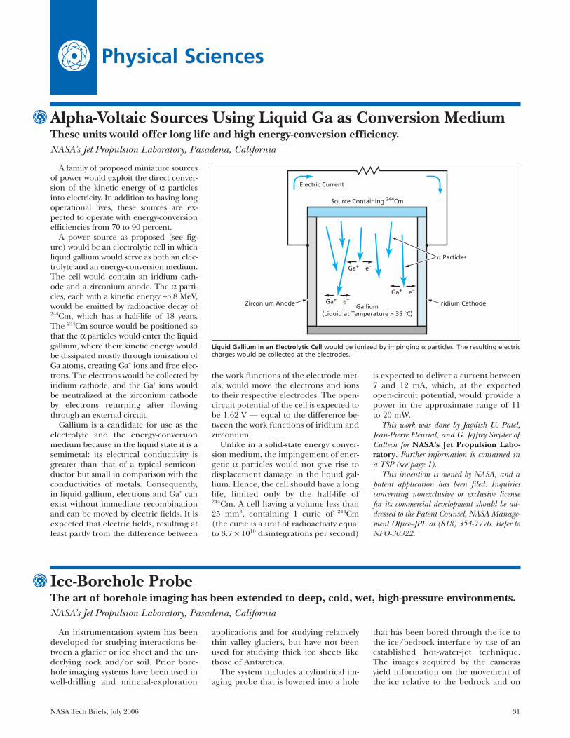
NASA Tech Briefs, July 2006 31
Physical Sciences
Alpha-Voltaic Sources Using Liquid Ga as Conversion MediumThese units would offer long life and high energy-conversion efficiency.NASA’s Jet Propulsion Laboratory, Pasadena, California
A family of proposed miniature sourcesof power would exploit the direct conver-sion of the kinetic energy of α particlesinto electricity. In addition to having longoperational lives, these sources are ex-pected to operate with energy-conversionefficiencies from 70 to 90 percent.
A power source as proposed (see fig-ure) would be an electrolytic cell in whichliquid gallium would serve as both an elec-trolyte and an energy-conversion medium.The cell would contain an iridium cath-ode and a zirconium anode. The α parti-cles, each with a kinetic energy ~5.8 MeV,would be emitted by radioactive decay of244Cm, which has a half-life of 18 years.The 244Cm source would be positioned sothat the α particles would enter the liquidgallium, where their kinetic energy wouldbe dissipated mostly through ionization ofGa atoms, creating Ga+ ions and free elec-trons. The electrons would be collected byiridium cathode, and the Ga+ ions wouldbe neutralized at the zirconium cathodeby electrons returning after flowingthrough an external circuit.
Gallium is a candidate for use as theelectrolyte and the energy-conversionmedium because in the liquid state it is asemimetal: its electrical conductivity isgreater than that of a typical semicon-ductor but small in comparison with theconductivities of metals. Consequently,in liquid gallium, electrons and Ga+ canexist without immediate recombinationand can be moved by electric fields. It isexpected that electric fields, resulting atleast partly from the difference between
the work functions of the electrode met-als, would move the electrons and ionsto their respective electrodes. The open-circuit potential of the cell is expected tobe 1.62 V — equal to the difference be-tween the work functions of iridium andzirconium.
Unlike in a solid-state energy conver-sion medium, the impingement of ener-getic α particles would not give rise todisplacement damage in the liquid gal-lium. Hence, the cell should have a longlife, limited only by the half-life of244Cm. A cell having a volume less than25 mm3, containing 1 curie of 244Cm(the curie is a unit of radioactivity equalto 3.7 × 10¹⁰ disintegrations per second)
is expected to deliver a current between7 and 12 mA, which, at the expectedopen-circuit potential, would provide apower in the approximate range of 11to 20 mW.
This work was done by Jagdish U. Patel,Jean-Pierre Fleurial, and G. Jeffrey Snyder ofCaltech for NASA’s Jet Propulsion Labo-ratory. Further information is contained ina TSP (see page 1).
This invention is owned by NASA, and apatent application has been filed. Inquiriesconcerning nonexclusive or exclusive licensefor its commercial development should be ad-dressed to the Patent Counsel, NASA Manage-ment Office–JPL at (818) 354-7770. Refer toNPO-30322.
Liquid Gallium in an Electrolytic Cell would be ionized by impinging α particles. The resulting electriccharges would be collected at the electrodes.
Ga+ e–
Ga+ e–
Ga+ e–
Gallium(Liquid at Temperature > 35 °C)
Zirconium Anode Iridium Cathode
Electric Current
Source Containing 244Cm
NPO30322
8-30-01 bs
α Particles
Ice-Borehole ProbeThe art of borehole imaging has been extended to deep, cold, wet, high-pressure environments.NASA’s Jet Propulsion Laboratory, Pasadena, California
An instrumentation system has beendeveloped for studying interactions be-tween a glacier or ice sheet and the un-derlying rock and/or soil. Prior bore-hole imaging systems have been used inwell-drilling and mineral-exploration
applications and for studying relativelythin valley glaciers, but have not beenused for studying thick ice sheets likethose of Antarctica.
The system includes a cylindrical im-aging probe that is lowered into a hole
that has been bored through the ice tothe ice/bedrock interface by use of anestablished hot-water-jet technique.The images acquired by the camerasyield information on the movement ofthe ice relative to the bedrock and on

visible features of the lower structure ofthe ice sheet, including ice layersformed at different times, bubbles, andmineralogical inclusions. At the time ofreporting the information for this arti-cle, the system was just deployed in twoboreholes on the Amery ice shelf inEast Antarctica and after successful2000–2001 deployments in 4 boreholesat Ice Stream C, West Antarctica, and in2002 at Black Rapids Glacier, Alaska.
The probe is designed to operate attemperatures from –40 to +40 °C andto withstand the cold, wet, high-pres-sure [130-atm (13.20-MPa)] environ-ment at the bottom of a water-filledborehole in ice as deep as 1.6 km. Acurrent version is being outfitted toservice 2.4-km-deep boreholes at theRutford Ice Stream in West Antarctica.The probe (see figure) contains a side-looking charge-coupled-device (CCD)camera that generates both a real-timeanalog video signal and a sequence ofstill-image data, and contains a digitalvideotape recorder. The probe alsocontains a downward-looking CCD ana-log video camera, plus halogen lampsto illuminate the fields of view of bothcameras. The analog video outputs ofthe cameras are converted to opticalsignals that are transmitted to a surfacestation via optical fibers in a cable.Electric power is supplied to the probethrough wires in the cable at a poten-tial of 170 VDC. A DC-to-DC convertersteps the supply down to 12 VDC forthe lights, cameras, and image-data-transmission circuitry. Heat generatedby dissipation of electric power in theprobe is removed simply by conductionthrough the probe housing to the adja-cent water and ice.
One of the new, creative, and very im-portant attributes of this system is itsability to provide the scientist/operatorwith direct real-time imaging of the icein front of the cameras. This allows real-time interaction of a knowledgeable ob-server and control over when to stop tostudy further, as well as the two-way com-mand and control that lets onezoom/focus into the ice structure to get“internal” versus wall-structure views at a100- to 200-mm scale.
The probe is lowered into the bore-hole by using the cable as a tether. Thecable is 1.6 km long and is wound on aspool about 0.9 m in diameter. Thespool is rotated by a three-phase ACmotor to pay out or pull in the cable ata speed of about 1 m/s. In addition tothe wires for transmitting power andthe optical fibers for transmitting data,
the cable contains strengthening mem-bers and includes a waterproof cover.The cable, the spool, the motor, and asled on which the spool and motor aremounted have a total mass of 180 kg.Other equipment in the surface stationincludes the following: two video moni-tors that display the current video feedsfrom each camera; two digital videotape recorders that digitize the incom-ing analog video images and store theresulting data for subsequent analysis;and a computer that is used to controlthe operation of the probe and, afterimage data have been acquired, to digi-tally manipulate the images and analyzetheir contents.
All the image data are time-tagged toenable detailed correlations of images
during post factum analysis. To assist anoperator in subsequently locatingunique image features, the real-timevideo display contains subwindows thatindicate depth and time. The highest-quality digital images are recorded by adigital videotape recorder within theside-looking camera. The videotape isremoved from the probe after theprobe has been returned to the surfacestation. Time tagging provides a directcorrelation between these taped imagesand the ones recorded in the surfacestation.
This work was done by Alberto Behar,Frank Carsey, Arthur Lane, and Herman En-gelhardt of Caltech for NASA’s Jet Propul-sion Laboratory. Further information iscontained in a TSP (see page 1). NPO-40500
32 NASA Tech Briefs, July 2006
A Cylindrical Probe Housing containing two cameras is lowered to the bottom of a borehole in ice toacquire images of ice structures, inclusions, and ice/bedrock interactions.
PowerConverter
Water-FilledBorehole
Bedrock
Cable
Ice
Electronic-to-OpticalVideo Converter
Ring for AttachingWeight-Bearing Portion
of Cable to Housing Part of Cable ContainingWires and Optical Fibers
Power Converter
Side-LookingCamera
Downward-LookingCamera
HalogenLamps
12cm
63.5cm
NPO40500ABPI
11-30-03 bs

A family of proposed miniaturesources of power would exploit the di-rect conversion of the kinetic energy ofα particles into electricity in diamondsemiconductor diodes. These powersources would function over a widerange of temperatures encountered interrestrial and outer-space environ-ments. These sources are expected tohave operational lifetimes of 10 to 20years and energy conversion efficiencies>35 percent.
A power source according to the pro-posal would include a pair of devices likethat shown in the figure. Each device wouldcontain Schottky and p/n diode devicesmade from high-band-gap, radiation-harddiamond substrates. The n and p layers inthe diode portion would be doped sparsely(<1014 cm-3) in order to maximize the vol-ume of the depletion region and therebymaximize efficiency. The diode layerswould be supported by an undoped dia-mond substrate.
The source of α particles would be athin film of 244Cm (half-life 18 years) sand-
wiched between the two paired devices.The sandwich arrangement would forcealmost every α particle to go through theactive volume of at least one of the de-vices. Typical α particle track lengths inthe devices would range from 20 to 30 mi-crons. The α particles would be made tostop only in the undoped substrates toprevent damage to the crystalline struc-tures of the diode portions.
The overall dimensions of a typicalsource are expected to be about 2 by 2by 1 mm. Assuming an initial 244Cmmass of 20 mg, the estimated initial out-
put of the source is 20 mW (a current of20 mA at a potential of 1 V).
This work was done by Jagdish U. Patel,Jean-Pierre Fleurial, and Elizabeth Kolawa ofCaltech for NASA’s Jet Propulsion Labo-ratory. Further information is contained ina TSP (see page 1).
This invention is owned by NASA, and apatent application has been filed. Inquiriesconcerning nonexclusive or exclusive licensefor its commercial development should be ad-dressed to the Patent Counsel, NASA Manage-ment Office–JPL at (818) 354-7770. Refer toNPO-30323.
NASA Tech Briefs, July 2006 33
This Diamond Diode is one of two that would be sandwiched together with a thin film of 244Cm, whichis a source of α particles. The sandwich structure would constitute an alpha-voltaic device.
Ohmic Contact Al All Around
P-Doped Diamond Boron 1019/cm3
N- Doped Silicon Substrate 5 × 10¹⁵/cm3
NPO30323
9-7-01 bs
Top Ohmic Contact Gold
Alpha-Voltaic Sources Using Diamond as Conversion MediumCompact, long-lived solid-state devices would tolerate wide temperature ranges. NASA’s Jet Propulsion Laboratory, Pasadena, California
White-Light Whispering-Gallery-Mode Optical ResonatorsOverlapping resonator modes are exploited to obtain wide, high-Q spectra.NASA’s Jet Propulsion Laboratory, Pasadena, California
Whispering-gallery-mode (WGM) opti-cal resonators can be designed to exhibitcontinuous spectra over wide wavelengthbands (in effect, white-light spectra), withultrahigh values of the resonance qualityfactor (Q) that are nearly independent offrequency. White-light WGM resonatorshave potential as superior alternatives to(1) larger, conventional optical res-onators in ring-down spectroscopy, and(2) optical-resonator/electro-optical-modulator structures used in coupling ofmicrowave and optical signals in atomicclocks. In these and other potential appli-cations, the use of white-light WGM res-onators makes it possible to relax the re-quirement of high-frequency stability oflasers, thereby enabling the use ofcheaper lasers.
In designing a white-light WGM res-onator, one exploits the fact that thedensity of the mode spectrum increasespredictably with the thickness of the
Figure 1. Cleaved Optical Fibers tangent to the rim of the resonator disk are used to couple light intoand out of the disk. The fibers are shifted with respect to the middle of the rim to obtain a high de-gree of interaction with all the WGM modes.
ResonatorDisk
Cleaved Optical Fiber
Input Output
NPO42221 Fig 1 ABPI
8-15-05 bs

resonator disk. By making the res-onator disk sufficiently thick, one canmake the frequency differences be-tween adjacent modes significantly lessthan the spectral width of a singlemode, so that the spectral peaks of ad-jacent modes overlap, making the res-onator spectrum essentially continu-ous. Moreover, inasmuch as the Qvalues of the various modes are deter-
mined primarily by surface Rayleighscattering that does not depend onmode numbers, all the modes havenearly equal Q. By use of a proper cou-pling technique, one can ensure excita-tion of a majority of the modes.
For an experimental demonstrationof a white-light WGM resonator, a res-onator disk 0.5-mm thick and 5 mm indiameter was made from CaF2. The
shape of the resonator and the fiber-optic coupling arrangement were asshown in Figure 1. The resonator was ex-cited with laser light having a wave-length of 1,320 nm and a spectral widthof 4 kHz. The coupling efficiency ex-ceeded 80 percent at any frequency towhich the laser could be set in its tuningrange, which was >100-GHz wide.
The resonator response was charac-terized by means of ring-down tests inwhich the excitation was interrupted bya shutter having a rise and a fall time of5 ns. The ring-down time of photodi-odes and associated circuitry used tomeasure the interrupted excitationand the resonator output was <1 ns.Figure 2 shows the shapes of represen-tative input and output light pulses.The average ring-down time was foundto be 120 ns, corresponding to Q ≈ 2 ×10⁸. The variations of Q with the lasercarrier frequency were found to be <5percent. Hence, the resonator wasshown to have the desired “white light”properties.
This work was done by Andrey Matsko,Anatoliy Savchenkov, and Lute Maleki ofCaltech for NASA’s Jet Propulsion Labo-ratory. Further information is contained ina TSP (see page 1).
This invention is owned by NASA, and apatent application has been filed. Inquiriesconcerning nonexclusive or exclusive licensefor its commercial development should be ad-dressed to the Patent Counsel, NASA Man-agement Office–JPL. Refer to NPO-42221.
34 NASA Tech Briefs, July 2006
Figure 2. Normalized Power Levels of input and output pulses of light, as functions of time, were de-termined in the setup depicted in Figure 1. The small amplitude modulation in the ring-down tail wasattributed to slight non-preservation of orthogonality between resonator modes — an artifact of theinput/output coupling technique.
Input
Output
–200 0Time, ns
No
rmal
ized
Op
tica
lPo
wer
0.0
0.5
1.0
200 400
NPO42221 Fig 2ABPI
8-15-05 bs

NASA Tech Briefs, July 2006 35
Books & Reports
Controlling Attitude of a Solar-Sail SpacecraftUsing Vanes
A paper discusses a concept for con-trolling the attitude and thrust vector ofa three-axis stabilized Solar Sail space-craft using only four single degree-of-freedom articulated spar-tip vanes. Thevanes, at the corners of the sail, would beturned to commanded angles about thediagonals of the square sail. Commandswould be generated by an adaptive con-troller that would track a given trajectorywhile rejecting effects of such distur-bance torques as those attributable tooffsets between the center of pressureon the sail and the center of mass. Thecontroller would include a standard pro-portional + derivative part, a feedfor-ward part, and a dynamic componentthat would act like a generalized integra-tor. The controller would globally trackreference signals, and in the presence ofsuch control-actuator constraints as satu-ration and delay, the controller wouldutilize strategies to cancel or reducetheir effects. The control scheme wouldbe embodied in a robust, nonlinear al-gorithm that would allocate torquesamong the vanes, always finding a stablesolution arbitrarily close to the globaloptimum solution of the control effortallocation problem. The solution wouldinclude an acceptably small angle, slowlimit-cycle oscillation of the vanes, whileproviding overall thrust vector pointingstability and performance.
This work was done by Edward Mettler, AhmetAcikmese, and Scott Ploen of Caltech for NASA’s
Jet Propulsion Laboratory. Further informa-tion is contained in a TSP (see page 1).
The software used in this innovation isavailable for commercial licensing. Pleasecontact Karina Edmonds of the CaliforniaInstitute of Technology at (626) 395-2322.Refer to NPO-42156.
Wire-Mesh-Based Sorber for Removing ContaminantsFrom Air
A paper discusses an experimentalregenerable sorber for removing CO2
and trace components — principally,volatile organic compounds, halocar-bons, and NH3 — from spacecraftcabin air. This regenerable sorber is aprototype of what is intended to be alightweight alternative to activated-car-bon and zeolite-pellet sorbent bedsnow in use. The regenerable sorberconsists mainly of an assembly of com-mercially available meshes that havebeen coated with a specially-formu-lated washcoat containing zeolites.The zeolites act as the sorbents whilethe meshes support the zeolite-contain-ing washcoat in a configuration that af-fords highly effective surface area forexposing the sorbents to flowing air.The meshes also define flow pathscharacterized by short channel lengthsto prevent excessive buildup of flowboundary layers. Flow boundary layerresistance is undesired because it canimpede mass and heat transfer. Thetotal weight and volume comparisonversus the atmosphere revitalization
equipment used onboard the Interna-tional Space Station for CO2 and trace-component removal will depend uponthe design details of the final embodi-ment. However, the integrated mesh-based CO2 and trace-contaminant re-moval system is expected to provideoverall weight and volume savings byeliminating most of the trace-contami-nant control equipment presently usedin parallel processing schemes tradi-tionally used for spacecraft. The mesh-based sorbent media enables integrat-ing the two processes within a compactpackage. For the purpose of regenera-tion, the sorber can be heated by pass-ing electric currents through themetallic meshes combined with expo-sure to space vacuum. The minimalthermal mass of the meshes offers thepotential for reduced regeneration-power requirements and cycle time re-quired for regeneration compared to re-generable sorption processes now in use.
This work was done by Jay Perry of Mar-shall Space Flight Center, and Subir Roy-choudhury and Dennis Walsh of PrecisionCombustion, Inc.
In accordance with Public Law 96-517,the contractor has elected to retain title to thisinvention. Inquiries concerning rights for itscommercial use should be addressed to:
Precision Combustion, Inc.410 Sackett Point RoadNorth Haven, CT 06473-3106Phone No.: (203) 287-3700 Fax No.: (203) 287-3710Refer to MFS-32308-1, volume and num-
ber of this NASA Tech Briefs issue, and thepage number.


National Aeronautics andSpace Administration