tekla structures 2017 - tekla user assistance · 1.1 temporary object ids in single-user models and...
TRANSCRIPT

Tekla Structures 2017BETA Release notes
January 2017
©2017 Trimble Solutions Corporation

Contents
1 Tekla Structures 2017 BETA release notes.................................. 51.1 Temporary object IDs in single-user models and model dump
removed............................................................................................................. 6Object IDs changed to GUIDs................................................................................................. 6Model dump no longer available........................................................................................... 7
1.2 User interface improvements..........................................................................8Saving backup copies of models............................................................................................8Making company-level customizations................................................................................. 8More visual copying of object properties..............................................................................9Improvements in the contextual toolbar.............................................................................. 9Switching tooltips on or off.................................................................................................. 12
1.3 Modeling improvements................................................................................ 12Selecting objects hidden behind other objects..................................................................13Direct modification improvements......................................................................................13Bent plate improvements..................................................................................................... 21New snap settings..................................................................................................................23Custom Inquiry available in side pane................................................................................ 24New command for showing all detailing of a part.............................................................25Documentation updates for filtering.................................................................................. 25
1.4 Flexible new way to create reinforcement.................................................. 25Rebar sets - A new method to create reinforcement........................................................ 25
1.5 Faster synchronization and other Organizer and Task managerimprovements................................................................................................. 28Faster synchronization in Organizer................................................................................... 28Fluent and faster reporting in Organizer............................................................................ 29Use Task manager to show a sequence in the model.......................................................31
1.6 Drawing improvements..................................................................................32More informative opening of drawings.............................................................................. 32Improved drawing performance..........................................................................................33Mark drawings ready for issuing..........................................................................................33Both letters and numbers allowed in section view labels................................................ 34Delete marks of selected parts at one go...........................................................................35New gray drawing line colors............................................................................................... 36Fill available for neighbor parts........................................................................................... 37Improved custom grid labels................................................................................................37Add images from 2D Library................................................................................................ 38Selection filter button added to Selecting toolbar in drawings....................................... 39Openings and recesses drawn correctly.............................................................................39Inch marks now shown after fractions of an inch............................................................. 40Rich text file improvements..................................................................................................40Select all (Ctrl+A) in drawing texts....................................................................................... 40Improved snapshot overlay with color support.................................................................40AutoDrawings available in Quick Launch............................................................................41New option to define automatic hatches separately for Precast and CIP ..................... 41
2

Improvements in reinforcement dimensions.................................................................... 42Rebars visible in reference models in drawings................................................................ 45New content type option in Rebar mesh view creator .....................................................45New location for loading drawing presentation and dimensioning plug-ins ................ 46
1.7 Drawing sketching and snapping improvements........................................46Increased visualization in sketching tools.......................................................................... 47More flexibility to cover-up tools......................................................................................... 48Possibility to re-order objects.............................................................................................. 49Improved Copy with offset................................................................................................... 50Improved snapping in drawings.......................................................................................... 50Improved pattern lines..........................................................................................................52
1.8 Reference model and base point improvements........................................ 53Improvements in reference model change detection.......................................................53Improvements in reference model conversion management......................................... 56New macros for selecting converted or corresponding objects...................................... 57Other improvements in reference model handling...........................................................57Improvements in project base point functionality............................................................ 58
1.9 ToDos in Trimble Connector...........................................................................581.10 NC export improvements............................................................................... 60
New option allowing pop-marks for parts welded on site............................................... 60Pop-marks created based on the weld primary and secondary part............................. 60Maximum diameter for circular cuts to be drilled.............................................................60
1.11 Applications & components catalog and component improvements...... 60Change the order of groups in the Applications & components catalog........................61Concrete components...........................................................................................................61
1.12 New template attributes................................................................................62New attributes for getting information on marked ready for issuing status................. 62New attributes for reinforcement........................................................................................63
1.13 New and deleted advanced options............................................................. 63New advanced options..........................................................................................................63Deleted advanced options....................................................................................................64
2 Disclaimer.....................................................................................66
3

4

1 Tekla Structures 2017 BETArelease notes
Welcome to the Tekla Structures 2017 BETA release notes!
This version comes with many bug fixes and a bunch of new features. The keyfeatures of this new version include:
• Temporary object IDs in single-user models and model dump removed(page 6)
• User interface improvements (page 8)
• Modeling improvements (page 12)
• Flexible new way to create reinforcement (page 25)
• Faster synchronization and other Organizer and Task managerimprovements (page 28)
• Drawing improvements (page 32)
• Drawing sketching and snapping improvements (page 46)
• Reference model and base point improvements (page 53)
• ToDos in Trimble Connector (page 58)
• NC export improvements (page 60)
• Applications & components catalog and component improvements(page 60)
• New template attributes (page 62)
• New and deleted advanced options (page 63)
Fixes by service pack or progress release
Follow the links below for information on fixes made in each currentlyavailable service pack and progress release:
• There are currently no service packs or progress releases available for thisversion.
Tekla Structures 2017 BETA release notes 5

Compatibility
We suggest that you complete any unfinished models using your currentversion of Tekla Structures.
This version is not backwards compatible. When you create or save a model inTekla Structures 2017, you cannot open it in older versions due to databasedifferences.
Tekla Structures 2017 can only be installed on 64-bit Windows operatingsystems. Tekla Structures 21.1 was the last version that supports installationon 32-bit Windows.
See the hardware recommendations for more information.
Administrator's release notes
Advanced users should read the Tekla Structures administrator's release notesfor information on how to apply the additional customizations available in thisrelease.
Localization release notes
Environment-specific changes are explained in the Localization release notes.
Tekla Open API release notes
The Tekla Open API release notes are included in the Tekla Open API StartupPackage, which you can download from Tekla Warehouse.
1.1 Temporary object IDs in single-user models andmodel dump removedTo improve the reliability and consistency of Tekla Structures, object IDs arenow temporary also in single-user models. Due to this change, the modeldump functionality has been removed.
Object IDs changed to GUIDsObject IDs have now been largely replaced by globally unique identifiers(GUID) in Tekla Structures. GUID is a permanent object property and can beused to identify objects reliably.
The numerical object IDs are now temporary information in all model types,including single-user and multi-user models. The ID number of the object maychange when the model is reopened, or when the read in command is used inTekla Model Sharing, and therefore the ID cannot be used as an objectidentifier in drawings, reports, and filters, for example.
Tekla Structures 2017 BETA release notes 6 Temporary object IDs in single-user models andmodel dump removed
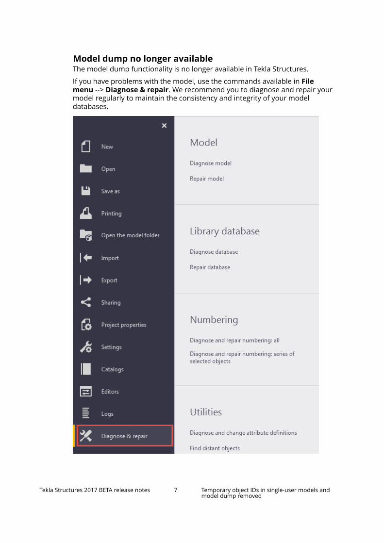
Model dump no longer availableThe model dump functionality is no longer available in Tekla Structures.
If you have problems with the model, use the commands available in Filemenu --> Diagnose & repair. We recommend you to diagnose and repair yourmodel regularly to maintain the consistency and integrity of your modeldatabases.
Tekla Structures 2017 BETA release notes 7 Temporary object IDs in single-user models andmodel dump removed

1.2 User interface improvementsTekla Structures 2017 comes with the following improvements in the userinterface:
Saving backup copies of modelsyou have a new option to save and create a backup copy of your model. Thebackup copy will have the same GUIDs (globally unique identifiers) as theoriginal.
Making company-level customizationsYou can now distribute customizations to a large group of users by using firmand/or environment folders.
• To distribute customized contextual toolbars, place the entireContextualToolbar folder (located in ..\Users\<user>\AppData\Local\Trimble\TeklaStructures\<version>) in your company'sfirm folder or in the system folder, which is located under yourenvironment folder: ..\ProgramData\Tekla Structures\<version>\Environments\<environment>\system.
• To distribute customized ribbons, place the entire Ribbon folder (locatedin ..\Users\<user>\AppData\Local\Trimble\TeklaStructures\<version>\UI) in your company's firm folder or in the system folder,which is located under your environment folder: ..\ProgramData\TeklaStructures\<version>\Environments\<environment>\system.
• To distribute individual ribbon tabs, create a custom tab file and place it inyour company's firm folder, under Ribbons\CustomTabs\Modeling orRibbons\CustomTabs\Drawing, depending on whether you want the tabto appear in the modeling or drawing ribbon (or both). Alternatively, youcan create the same folder structure in your environment folder, under ..
Tekla Structures 2017 BETA release notes 8 User interface improvements

\ProgramData\Tekla Structures\<version>\Environments\<environment>\system\.
For more information on custom tabs and company-level customizations, seeTekla Structures administrator's release notes.
More visual copying of object propertiesNow the mouse cursor changes into a paintbrush if the Copy propertiescommand is active on the contextual toolbar.
For more information, see Copy properties from another object.
Improvements in the contextual toolbarTekla Structures 2017 contains many useful improvements for the contextualtoolbar:
• You can change the visibility of object types directly on the contextualtoolbar. Click the view to see the related contextual toolbar. Then click theeye button to display a list of object types:
Click the small eye buttons to show or hide certain object types. In the left-
hand column ( ), set the visibility of model objects. In the right-hand
column ( ), set the visibility of component objects.
Tekla Structures 2017 BETA release notes 9 User interface improvements

• You can now activate view filters, and color and transparency settings alsofrom the contextual toolbar. Click the view to see the related contextualtoolbar.
1. The left-hand list contains view filters.
2. The right-hand list contains color and transparency settings for modelobjects.
Tekla Structures 2017 BETA release notes 10 User interface improvements
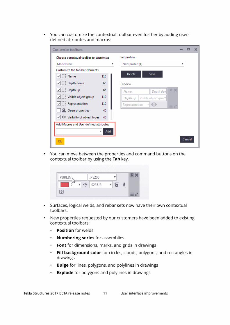
• You can customize the contextual toolbar even further by adding user-defined attributes and macros:
• You can move between the properties and command buttons on thecontextual toolbar by using the Tab key.
• Surfaces, logical welds, and rebar sets now have their own contextualtoolbars.
• New properties requested by our customers have been added to existingcontextual toolbars:
• Position for welds
• Numbering series for assemblies
• Font for dimensions, marks, and grids in drawings
• Fill background color for circles, clouds, polygons, and rectangles indrawings
• Bulge for lines, polygons, and polylines in drawings
• Explode for polygons and polylines in drawings
Tekla Structures 2017 BETA release notes 11 User interface improvements

• Direct modification settings are now located in an expandable section onthe contextual toolbar. Click the small triangle symbol to show or hide theoptions:
Switching tooltips on or offYou can now choose whether tooltips should be visible or not.
To switch the tooltips on or off, go to File menu --> Settings. Under Switches,select or clear the Tooltips check box.
1.3 Modeling improvements
Tekla Structures 2017 BETA release notes 12 Modeling improvements

Selecting objects hidden behind other objects• You can more easily select objects that are hidden behind other objects.
For example, you can select reinforcing bars even if they are hidden behindthe surface handle (the yellow area in the image) of a nearby object:
Direct modification improvements• In previous versions, you needed to press the Shift key when dragging a
direct modification handle to an existing snap point or line. This has beenchanged so that snapping to points and lines is enabled by default. If youtemporarily want to disable snapping to points and lines, press the Shiftkey.
• You can move point and line handles to any location in the 3D space byusing the new Move in 3D command. The command becomes available onthe contextual toolbar when you select a point or line handle.
Tekla Structures 2017 BETA release notes 13 Modeling improvements

• You can still restrict handle movement if needed. With point handles, youcan use the Move in XY plane and Move in Z direction options. With linehandles, you can use the Move in parallel direction and Move inperpendicular direction options. In plane views, the handles always stayin the view plane even if the Move in 3D command is switched on.
• You can also restrict handle movement to a selected part plane. This can beuseful when working with a sloped roof, for example. Click the Move inselected plane button on the contextual toolbar, select a part plane, and
Tekla Structures 2017 BETA release notes 14 Modeling improvements

then drag the handle to a new location. The handle can be moved in theselected plane only.
For example:
• Tekla Structures remembers the snap mode setting (Move in 3D / XYplane / Z direction / parallel direction / perpendicular direction) duringthe session.
• You can now control the visibility of all direct modification dimensions. Clickthe button to show the options, and then click the eye button to show orhide dimensions:
Tekla Structures 2017 BETA release notes 15 Modeling improvements
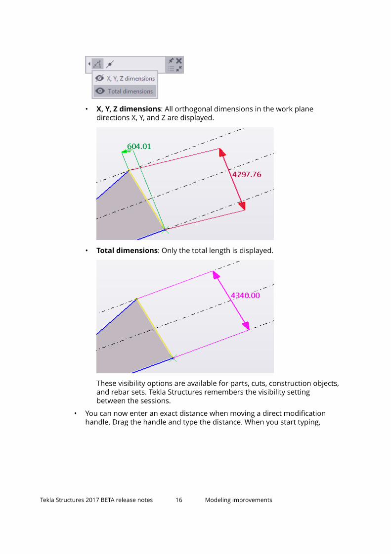
• X, Y, Z dimensions: All orthogonal dimensions in the work planedirections X, Y, and Z are displayed.
• Total dimensions: Only the total length is displayed.
These visibility options are available for parts, cuts, construction objects,and rebar sets. Tekla Structures remembers the visibility settingbetween the sessions.
• You can now enter an exact distance when moving a direct modificationhandle. Drag the handle and type the distance. When you start typing,
Tekla Structures 2017 BETA release notes 16 Modeling improvements

Tekla Structures displays the Enter a Numeric Location dialog boxautomatically:
• Polygon cuts now have a plane handle which can be used for modifying thethickness of the cut:
Tekla Structures 2017 BETA release notes 17 Modeling improvements

• Direct modification is now also available for line cuts:
Tekla Structures 2017 BETA release notes 18 Modeling improvements

• Tekla Structures now tries to keep dimension lines and values in the vieweven when you zoom in or move the view. Dimensions may be moved toanother side of the part, for example:
• Dimension arrowheads and custom part placing handles now keep thesame size, regardless of the zoom level:
Tekla Structures 2017 BETA release notes 19 Modeling improvements

• Tekla Structures now only shows the dimensions that are relevant in eachview. In the following example, the perpendicular (red) dimensions arevisible in the previous version of Tekla Structures but hidden in TeklaStructures 2017:
Part perspective view Part end view, TeklaStructures 2016i
Part end view, TeklaStructures 2017
• You can now create temporary reference points when creating new objectsusing direct modification.
Tekla Structures 2017 BETA release notes 20 Modeling improvements

Bent plate improvementsTekla Structures 2017 contains many useful improvements that help youmodify the shape of existing bent plates.
• You can edit the bend radius directly on the contextual toolbar:
• You can change the shape of the curved section by choosing one of thepredefined options:
Tapered bend
A gradual decrease in the widthbetween the parts. This is thedefault option.
Tekla Structures 2017 BETA release notes 21 Modeling improvements

Narrow bend
Constant width between theparts. The width is determined bythe narrowest part.
Wide bend
Constant width between theparts. The width is determined bythe widest part.
Tekla Structures 2017 BETA release notes 22 Modeling improvements

• You can also modify and fine-tune the shape manually by clicking the Moveboundaries button on the contextual toolbar. Then drag the boundaryhandles to change the shape of the curved section. For example:
• You can remove individual curved sections by clicking the Remove bendbutton on the contextual toolbar. For example:
New snap settingsGeneral snap settings are now available in File menu --> Settings --> Snapsettings. Previously, these settings were located in the Options dialog box,under Mouse settings.
Also new snap options for the Ortho tool have been added:
Tekla Structures 2017 BETA release notes 23 Modeling improvements

Custom Inquiry available in side pane
Custom Inquiry is now available in the side pane. Click the button in theside pane to view model object properties using Custom Inquiry.
Alternatively, you can still click the down arrow next to on the ribbon, andthen select Custom inquiry.
Custom Inquiry works in the same way as before, only the user interface hasbeen slightly improved.
For more information, see Custom inquiry and How to use the side pane.
Tekla Structures 2017 BETA release notes 24 Modeling improvements

New command for showing all detailing of a partA new command Display detailing is now available for showing all objectsand detailing related to a part. For example, you can use this command toexamine whether parts are cut or welded correctly.
1. Select a part.
2. Click Display detailing on the contextual toolbar.
Alternatively, you can press Alt+D, or use Quick Launch.
For steel parts, Tekla Structures displays all parts, bolts, welds, cuts, fittings,and other details belonging to the assembly, even if you had defined them ashidden in the display settings. For concrete parts, Tekla Structures displaysalso reinforcement, surface treatment, and surfaces.
Documentation updates for filteringThe instructions for the filtering functionality have now been revised, asrequested by many of our readers. Please note that the functionality itself hasnot been changed. The instructions now contain detailed information aboutthe various object properties that you can use in filter rules. Also moreinformation on how to use conditions and brackets have been included. Allexample filters have been checked and improved to contain more complexfilter rules, brackets, and so on.
1.4 Flexible new way to create reinforcement
Rebar sets - A new method to create reinforcementTekla Structures 2017 introduces rebar sets that are a very flexible andversatile method to create reinforcement. Using rebar sets you can reinforce
Tekla Structures 2017 BETA release notes 25 Flexible new way to create reinforcement

various areas in concrete parts, as well as in pour objects, or outside concreteobjects. Rebar sets are adaptive to the changes in concrete parts.
Rebar sets are reinforcing bars that you can easily modify as a group or only atcertain places. You can use direct modification and the new methods specificto rebar sets: guidelines, leg faces, and local modifiers.
Tekla Structures 2017 BETA release notes 26 Flexible new way to create reinforcement

You can cut rebar sets using the cutting commands on the Edit tab, andmodify the cuts using direct modification. You can also split bars with splitters,which are one type of modifiers.
When you create rebar sets at a face of a concrete part, for example, TeklaStructures automatically arranges overlapping bars to layers. If needed, youcan easily fine-tune the order of the layers.
The rebar set commands are available on the Concrete tab:
Tekla Structures 2017 BETA release notes 27 Flexible new way to create reinforcement

Rebar sets in drawings
The reinforcing bars that are created by using the rebar set commands areautomatically grouped for drawing marking and dimensioning purposes. Formore information about rebar sets in drawings, see Automatic grouping ofrebars sets for drawings.
1.5 Faster synchronization and other Organizer and Taskmanager improvementsTekla Structures 2017 introduces improvements in Organizer synchronizationand reporting. With Task manager, you can now show a sequence in themodel.
Faster synchronization in OrganizerOrganizer is synchronized significantly faster than before. Synchronizing
Organizer now updates all properties of the changed objects in theOrganizer database. This is useful especially if you have changed only a fewobjects in the model. Previously, the properties viewed in Organizer wereupdated at synchronization for all objects.
When you have viewed a property of any object in Object Browser, theproperty will be updated in the Organizer database at synchronization.
Tekla Structures 2017 BETA release notes 28 Faster synchronization and other Organizer andTask manager improvements

Note that in some cases the whole Organizer database is still synchronized.This happens when synchronizing a model for the first time, or when you haveenabled the pour functionality, for example.
Reloading Object Browser
When you reload Object Browser, the viewed properties are refreshed todisplay the current situation in the model. The refreshed properties are alsoupdated in the Organizer database.
When you have viewed a property of any object in Object Browser, theproperty will be updated in the Organizer database at synchronization.
Fluent and faster reporting in Organizer
View a limited number of objects in Object Browser
Object Browser has now a predefined limit for listing objects. As loadingobject properties takes time, the limit is useful if you have selected a largenumber of objects in the model or in the categories. When you select morethan the predefined number of objects, Object Browser does not at first showthe objects. Instead, Object Browser shows how many objects you haveselected and what the predefined limit is.
• Click to show the objects and the object properties stored in theOrganizer database.
• Click to reload the object properties and then show the objects.
You can also change the predefined limit by entering a number in the box. Thenumber you enter in the box becomes the default value. You can also set thelimit in Organizer Settings, on the Synchronization tab.
Tekla Structures 2017 BETA release notes 29 Faster synchronization and other Organizer andTask manager improvements

Show objects from the model or the categories
Object Browser automatically shows objects either from the model or fromthe categories based on what you have last selected. On the Object Browser
toolbar, the automatic selection button is selected by default. If you have acategory selected, Object Browser only shows the objects that are in thecategory. If you have selected objects in the model, Object Browser onlyshows these objects.
You can switch off the automatic selection to control the selection. Click the
button to select the other selection buttons:
• Click to show objects from the model.
• Click to show objects from the categories.
Set Object Browser summary row details
The options for defining how property values are shown in the ObjectBrowser sum row and combined rows have been renamed in OrganizerSettings. The sum row option also has a new function.
• Use In sum row show to define how the property values are shown in thesum row. Previously, this option was called Show result in sum row.
As a new option for the sum row, you can now select Single value if youwant the sum row to show a property value only when all the objects inObject Browser have the same value in the property column.
• Use In combined row show to define how the property values are shownin combined rows. Previously, this option was called Show result incombined rows.
Tekla Structures 2017 BETA release notes 30 Faster synchronization and other Organizer andTask manager improvements

Pours in Organizer
When you have the pour functionality enabled, Organizer shows the pourobject hierarchy instead of the cast-in-place object hierarchy.
Select categories
When you have selected a category in Organizer, the objects in the categorystay selected when you right-click another category. Right-clicking a categorydoes not select the category anymore. When you right-click a category, you canonly add objects to the category. To use all the category commands, you needto select the category first.
View objects in a pie chart
When you have grouped objects in Object Browser, you can now create a piechart to view the ratio of the number of objects included in the groups. PressAlt + F12 to create the pie chart. You can copy the pie chart to any documentby using the Ctrl + C and Ctrl + V commands.
Use Task manager to show a sequence in the model
You can now show a sequence in the model by using Task manager.
In the Task information dialog box, first set the sequencing order for theobjects on the Objects tab. Then select the relevant objects in the table and
click the Play button. The objects are selected in the model in the sameorder as they are listed on the Objects tab.
You can change the speed of object selection by typing a different number in
the box next to the Play button . The default is 1 second.
Tekla Structures 2017 BETA release notes 31 Faster synchronization and other Organizer andTask manager improvements

1.6 Drawing improvementsTekla Structures 2017 has several improvements and new features in drawingsincluding improved drawing opening, better drawing performance, new optionfor marking drawings ready for issuing, new command for deleting marks forselected parts at one go, new gray line colors, fills available for neighbor parts,more consistent logic in openings and recesses, colors available in snapshotoverlays, improvements in reinforcement dimensions, automatic hatchesavailable separately for precast and cast in place, improvements in customgrid labels, and many more.
More informative opening of drawingsNow you get more information on what is going on while you open drawings:
• You can now see a snapshot of the drawing if one has been created for theparticular drawing.
• A message box is displayed showing the progress and what is happening.
• The Cancel button in the message box now works and you are able tocancel the opening of the drawing.
Tekla Structures 2017 BETA release notes 32 Drawing improvements

Improved drawing performanceDrawing performance was improved in several operations:
• Drawing part, reinforcement and annotation mark update
• Reference model rendering. Now drawings open faster also whenreference models use hidden lines.
• Object level settings
• Filtering
• Rebar rendering
• Hatching of parts faces and sections
• Cloning
Mark drawings ready for issuingWhen a drawing is ready to be released for fabrication, you can now mark itready for issuing by using the new option Ready for issuing On/Off in theDrawing list. You can also find this command in the pop-up menu.
• When there are changes in the model, the geometry of the issued drawingsis updated. The drawing can still be edited and updated, and works just likeany other drawing.
• When a drawing is marked ready for issuing, it is flagged with a green checkmark in the new Ready for issuing column in the Drawing list. You cancheck who marked the drawing from the new Ready for issuing bycolumn.
• The Mark drawing ready for issuing option has replaced the Disableautomatic updating (Freeze) option in the save confirmation messagebox, which appears when you close an unsaved drawing.
• The Freeze option is still available in the Drawing list for those who needit.
• Template Editor contains new attributes IS_READY_FOR_ISSUE and READY_FOR_ISSUE_BY for this new functionality, which you can include inreports, for example.
Tekla Structures 2017 BETA release notes 33 Drawing improvements

Both letters and numbers allowed in section view labelsThere is a new option available in Section view properties in all drawing typesfor adjusting the section view and section symbol labels: Start number orletter of section view and symbol label.
• You can enter any number starting from 1, or any letter A - Z or a - z (alsoshown in uppercase in the label).
• If you use a letter, and the entered string is longer than one letter, only thefirst letter is shown. If you use numbers, all entered numbers are shown.
• The start number in the label changes only when you change it in thedrawing properties before creating a drawing, and when you change it inan existing drawing and recreate the drawing, in which case the labels forall automatically included section views and all new section views willchange.
Tekla Structures 2017 BETA release notes 34 Drawing improvements

Delete marks of selected parts at one goWith the new command Delete part mark you can easily delete part marks ofparts that you have selected. This command comes in very handy when you donot want to show marks for neighbor parts or neighbor reinforcement, forexample.
• To delete marks, activate the Select parts selection switch, select the partsusing a proper selection filter, right-click and select Delete part mark.
In the following example, you want to delete all marks except marks forcast units with a position number B/1. When you apply this filter, activate
the Select parts selection switch, and use area select to select theparts, all other parts get selected.
The image below shows the parts that have been selected and the marksthat you want to delete.
To delete the marks, right-click and select Delete part mark.
Tekla Structures 2017 BETA release notes 35 Drawing improvements

• You can delete all other mark types, except weld marks.
New gray drawing line colors• Now lines in all drawing types, in all building objects, annotations,
dimensions, and drawing sketch objects have four new gray colorsavailable. The different gray shades are true colors in the way that they willkeep their color regardless of the drawing color mode, all the way toprinting.
Below is an example of architectural linework drawn direct from anarchitectural IFC model. Light gray is used here.
Tekla Structures 2017 BETA release notes 36 Drawing improvements

Fill available for neighbor parts• The Fill tab has been added to the Neighbor part properties. For example,
if your drawing shows a pour, you may want to show other parts with adifferent color than pours, and add a different fill.
Improved custom grid labels• The Advanced grid label properties dialog box has now a new user
interface. Earlier there were problems with the dialog box size and buttonsthat were not working properly.
• In custom grids, you can now select which symbol file to use, and select thesymbol by double-clicking it in a separate window, which opens when youclick the ... button.
Tekla Structures 2017 BETA release notes 37 Drawing improvements

• Grid labels created in Tekla Structures version 2016i are not compatiblewith version 2017. You need to recreate the labels.
• Now you can also enter the grid axis text and prefixes in the Advancedgrid label properties dialog box. Earlier, these values could only be enteredin the user-defined grid properties in the model.
• The minimum allowed size in the Grid number and Grid text boxes in theAdvanced grid label properties dialog box is 1.0.
Add images from 2D LibraryYou can now insert images to drawings from the 2D Library.
• Open the 2D Library and browse for the folder containing the desiredimage files. Alternatively, you can move your image files to the \DrawingDetails folder under the current model folder. To place the image, selectthe file and click the drawing view or drawing.
• If the file is inserted from outside the model folder, Tekla Structures willcopy the file to the model folder first, and the insertion path will be relativeto that.
• You cannot include images in new details.
Tekla Structures 2017 BETA release notes 38 Drawing improvements

Selection filter button added to Selecting toolbar indrawings
• Now the Selecting toolbar also contains a Selection filter button inthe drawing mode. When you click this button, the Selection filter dialogbox is displayed allowing you to create and modify drawing selection filters.
• You can also open the Selection filter dialog box by pressing Ctrl+G orentering Selection filter in the Quick Launch box.
Openings and recesses drawn correctly• The openings and recesses logic is now more consistent. If you use a
polygon or a part cut for cutting, the resulting opening or recess is visible indrawings. If the cut is created by modifying part points, the opening/recessis not shown. Hollow profiles are now drawn correctly using correctsymbols. Complex cuts, like L, U or O shapes, are not supported.
• Note that if you open a drawing from an older Tekla Structures version, theopening and recess symbols may change.
• The following advanced options define how the openings and recesses areshown:
XS_USE_CROSS_FOR_OPENING_SYMBOL
XS_USE_OPENING_SYMBOL_IN_CORNER_HOLES
XS_USE_OPENING_SYMBOL_IN_BORDER_HOLES
Tekla Structures 2017 BETA release notes 39 Drawing improvements

Inch marks now shown after fractions of an inch• Now inch marks are also shown after fractions of an inch in dimension
texts.
Rich text file improvements• Now you can also use underscore, hieroglyphs, superscript and subscript in
the .rtf files added in drawings with the command Rich text.Nested lists are also supported.
Select all (Ctrl+A) in drawing texts• You can now select all text in the Text box in the Text properties dialog
box by pressing Ctrl+A.
Improved snapshot overlay with color support• In model snapshot overlays, the plan views are now located on the correct
create plane.
• The text "Snapshot" and the layout of the drawing are no longer displayedin the snapshot overlays in the model.
• You can now change the snapshot overlay color.
Tekla Structures 2017 BETA release notes 40 Drawing improvements

• You can now snap to drawing snapshot overlays with the Snap to
geometry lines/points snap switch .
AutoDrawings available in Quick LaunchThe AutoDrawings command is again available as a separate command. AnAutoDrawings wizard is a file-based wizard consisting of several sets ofdrawing requests containing drawing, attribute and part settings to apply toselected objects, as well as a selection filter.
• You can open the AutoDrawings dialog box by entering AutoDrawings inQuick Launch.
• You can also create a keyboard shortcut for starting AutoDrawings throughFile --> Settings --> Keyboard shortcuts.
New option to define automatic hatches separately forPrecast and CIPYou can now specify automatic hatches separately for cast-in-place andprecast parts using the new option Cast unit type in the drawing hatchschema file (.htc). This can be useful in GA drawings for presenting differenttypes of concrete structures, or in cast unit drawings for identifying differentconcrete layers in composite elements, such as double walls or half-slabs.
• The allowed values are Precast and CIP.
• There are separate .htc files for each drawing type.
Tekla Structures 2017 BETA release notes 41 Drawing improvements

• To be able to specify hatches separately, you need to select the appropriatecast unit type in the concrete part properties.
• Automatic hatching also supports the new gray scale colors. New colornumbers are 130 - 133 from darker to lighter.
Improvements in reinforcement dimensionsTekla Structures 2017 contains plenty of improvements and fixes in rebardimensioning:
• You can add tapered skewed and tapered curved dimensions to both endsof the part, and the dimension line follows the shape of the edge that isclosest to the location that you pick. The representation of the taperedskewed and tapered curved dimensions is set in Drawing dimensionssettings in the Options dialog box.
Tekla Structures 2017 BETA release notes 42 Drawing improvements

Now you can also add middle tags in curved rebar dimensions on the Tagstab in the Dimension Properties dialog box. In the example below, dualdimensions are applied so that you can see metric above and imperialbelow in the middle tag:
Tekla Structures 2017 BETA release notes 43 Drawing improvements

• There is one new option in the Curved dimension tag type list onthe Tags tab in the Dimension Properties dialog box. When you select thisoption, the dimension tag follows the dimension curve:
• When you select option , vertical rebar dimension tags are nowplaced correctly:
Tekla Structures 2017 BETA release notes 44 Drawing improvements

Rebars visible in reference models in drawings• Rebars are now shown in reference models in drawings.
New content type option in Rebar mesh view creator• RebarMeshViewCreator is a macro that you can use for creating drawing
views each containing one reinforcement mesh. A new option Unit oflength in text has been added in the Rebar mesh view creator dialog boxto control the unit of the wire length (L=…) text in the annotation text.
Tekla Structures 2017 BETA release notes 45 Drawing improvements
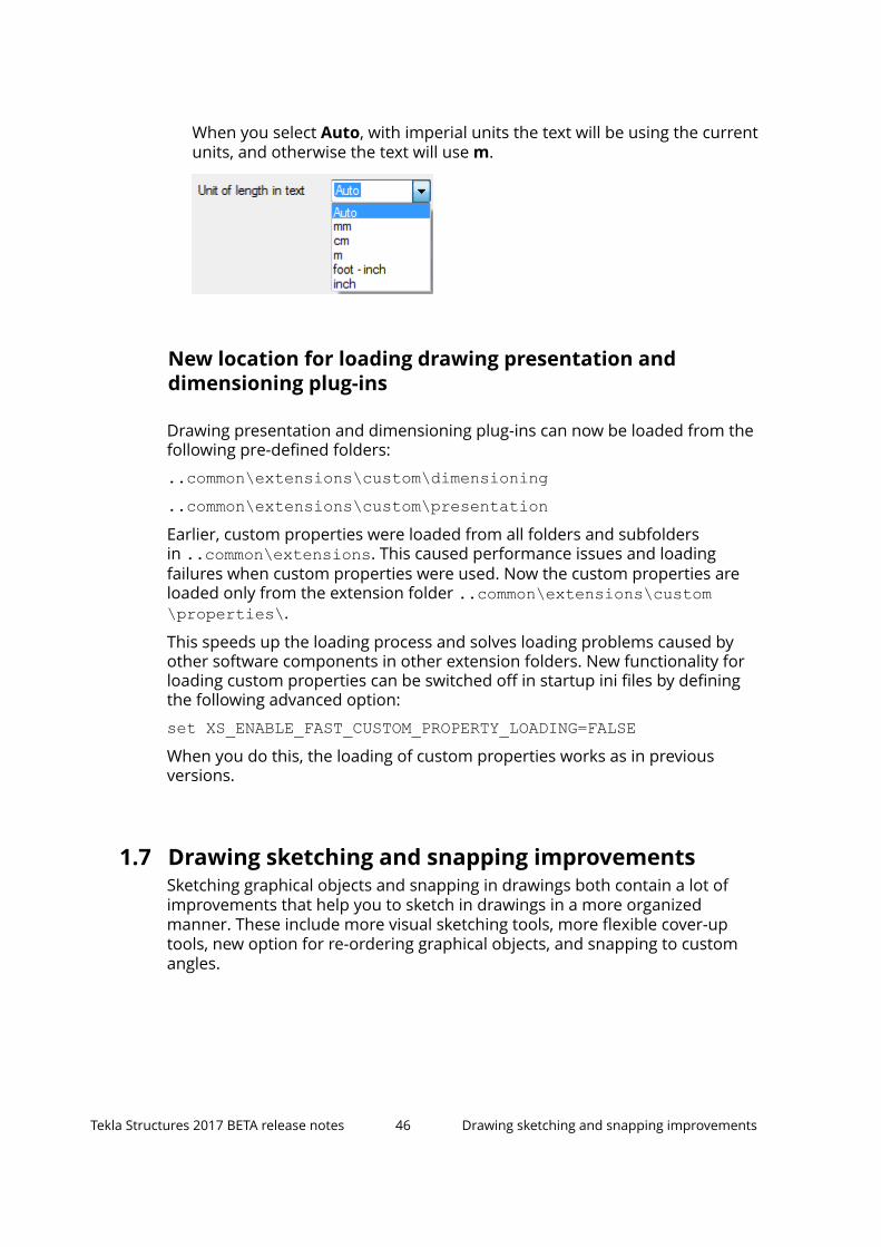
When you select Auto, with imperial units the text will be using the currentunits, and otherwise the text will use m.
New location for loading drawing presentation anddimensioning plug-ins
Drawing presentation and dimensioning plug-ins can now be loaded from thefollowing pre-defined folders:
..common\extensions\custom\dimensioning
..common\extensions\custom\presentationEarlier, custom properties were loaded from all folders and subfoldersin ..common\extensions. This caused performance issues and loadingfailures when custom properties were used. Now the custom properties areloaded only from the extension folder ..common\extensions\custom\properties\.
This speeds up the loading process and solves loading problems caused byother software components in other extension folders. New functionality forloading custom properties can be switched off in startup ini files by definingthe following advanced option:
set XS_ENABLE_FAST_CUSTOM_PROPERTY_LOADING=FALSEWhen you do this, the loading of custom properties works as in previousversions.
1.7 Drawing sketching and snapping improvementsSketching graphical objects and snapping in drawings both contain a lot ofimprovements that help you to sketch in drawings in a more organizedmanner. These include more visual sketching tools, more flexible cover-uptools, new option for re-ordering graphical objects, and snapping to customangles.
Tekla Structures 2017 BETA release notes 46 Drawing sketching and snapping improvements

Increased visualization in sketching tools
• Now when you draw graphical objects like polylines and polygons, you cansee the resulting shape right away. The line lengths are also shown.
• Radius is now shown when you draw arcs and circles.
• The target view scale is now applied when you copy graphical objects fromone view to another, which means that the scale of the object and therelated numerical information adjusts to the scale of the target view.
• Sketch object dimensions take into account dimension settings in drawingsin general. This means, for example, that units can be controlled in thesame way as for the other dimensions.
• Now numeric input works when you move polyline and polygon handles.
Tekla Structures 2017 BETA release notes 47 Drawing sketching and snapping improvements

More flexibility to cover-up tools
• Tekla Structures 2017 introduces two new cover-up tools:
Draw cover-up polyline
Draw cover-up polygon
• The name of the Cover-up area command is now Cover-uprectangle.
• You can explode a cover-up polyline into separate straight cover-up lines,and combine cover-up lines and polylines into closed cover-up polygons.
• The cover-up object dimensions are shown while you draw it, and alsowhen the object is selected, and you can resize and reshape the cover-upobjects by dragging the handles.
• Note that the Re-order command in the pop-up menu has no effect on thecover-up object. To have a cover-up area hiding sketch objects, such aspolygons and polylines, use Re-order for the sketch object and send itbehind model object.
Tekla Structures 2017 BETA release notes 48 Drawing sketching and snapping improvements

Possibility to re-order objectsIn drawings, you may want to indicate positions of openings, windows, doorsand such by sketching graphical objects. You can change the mutual order ofthe sketch objects (graphical objects), and the mutual order of the sketchobjects and model objects. You can bring sketch objects forward or in front ofother sketch objects, or send them backward or behind other sketch objects,and also send sketch objects behind model objects or bring them in front ofmodel objects. You can also re-order DWGs and images in the same way.
If you have several objects (objects on several layers), the drawing orderaffects on which layer the forward and backward commands place the objects.Newly created sketch objects are placed on their own layer in the drawingorder: the newest one on top of the older one.
• To re-order, right-click a sketch object, DWG or an image and click Re-order. Then select one of the following commands:
• Send backward: Moves the selected object one step closer to the backof all other sketch objects.
• Send to back: Places the selected object behind all other sketchobjects.
• Bring forward: Moves the selected object one step closer to the frontof all other sketch objects.
• Bring to front: Places the selected object in front all other sketchobjects.
• Send behind model objects: Places the object behind all modelobjects. You can also set this option in the sketch object propertiesdialog box (Behind model objects --> Yes).
• Bring in front of model objects : Places the object in front of all modelobjects. You can also set this option in the sketch object propertiesdialog box (Behind model objects --> No).
Showing an opening:
Tekla Structures 2017 BETA release notes 49 Drawing sketching and snapping improvements

Highlighting the footing area in a drawing by placing a gray polygon behindfootings:
• Note that sketch objects that are placed behind model objects cannot bere-ordered together with sketch objects that are placed in front of modelobjects.
Improved Copy with offset
• When you create a line with a bulge and copy the line using Copy withoffset , the created line now has the same bulge as the original one.
• If the rectangle has no bulges, the copied object will still be a rectangleafter you use Copy with offset, just like before. But if the original rectanglehas a bulge, it is not possible to copy it to a new rectangle using Copy withoffset. When you use Copy with offset, the new copied object will becomea polygon.
Improved snapping in drawings• You can now snap to custom angles in drawings. This is useful when you
are sketching polylines and polygons, for example.
• Angles become visible when you activate orthogonal snapping bypressing O (or selecting File --> Settings --> Ortho) and specify custom
Tekla Structures 2017 BETA release notes 50 Drawing sketching and snapping improvements

angles and/or snapping steps in the renewed Drawing snap settingsdialog box. To open this dialog box in drawing mode, click File -->Settings --> Snap settings.
• Using ortho snapping to custom angles is also useful if you need toplace annotation objects in a consistent manner, for example. In theexample below, you first add a text with a leader line using a 60 degreeangle to the part:
Then you will add a new text using the same angle:
Tekla Structures 2017 BETA release notes 51 Drawing sketching and snapping improvements

• Note that setting the snap settings in the model has no effect on adrawing, and vice versa.
• Free snapping in drawings is now based on the zooming level: Thecloser you zoom, the more exact you can sketch. For example, you can nowmore easily create rectangles that are of exact length when you zoomcloser. The snapping step changes from 1 to 1000 (1/16" - 5') depending onthe zoom level.
• You can now snap to drawing snapshot overlays with the Snap togeometry lines/points snap switch .
• Now you can snap to drawing layout items as well as to the drawingframe using the Snap to dimensions and mark lines snap switch .
Improved pattern lines• It is now easier to add symbols in pattern lines. You can now select the
symbol by double-clicking it in a separate window, which opens when youclick Select.
Tekla Structures 2017 BETA release notes 52 Drawing sketching and snapping improvements

• If you use dashed lines in a line pattern, the dashes are justified to thecorners of a line segment, so lines do not start with spaces. The dashes arejustified if the pattern is longer than the line itself. Printing and DWG/DXFexport do not support this change yet.
1.8 Reference model and base point improvementsReference models now use customizable comparison sets in change detection.There are some new controls making the comparison, change detection, andconversion management more fluent and extensive. In conversionsmanagement, the object type is now visible in the changes list. There are alsosome improvements in general reference model handling and base pointfunctionality.
Improvements in reference model change detection
Comparison sets
• Change detection in Tekla Structures now compares different versions ofthe reference model based on a comparison set, which tells you whetherTekla Structures considers a change in a property a change or not. You canuse the standard property comparison set, or define comparison sets ofyour own.
• In the reference model, when the change detection is active, the changeslist shows all deleted, changed, new and not changed objects. The property
Tekla Structures 2017 BETA release notes 53 Reference model and base point improvements

details list only contains those properties that are defined to be comparedby the current comparison set rules.
• To create a new comparison set, in Change detection section, click Comparison sets to open the Comparison sets dialog box. Add new rules
by clicking Add row, activate/deactivate fixed rules, enter a name for
the set, and click Save.
• If you decide that you do not need a comparison set, select it from the list
and click Delete. You can also delete individual rules that you havecreated by clicking Delete row.
Other improvements in reference model change detection
• There is now a new This model is newer check box in front of the file pathin change detection. Select this check box to define that the file shown inthe file path box is newer than the other compared file. If the file has beenupdated, it appears in the box automatically and the check box is selected.
Tekla Structures 2017 BETA release notes 54 Reference model and base point improvements

• It is now possible to compare as newer (default) or older.
• New columns Material, GUID and Profile were added in the changes list,and the ID column was removed.
• You now have a new check box Get selected from the model. When youselect it, and click an object in the model, Tekla Structures finds the objectrow in the changes list, sets the focus on that row, and shows the details listfor the selected object.
• You can zoom to deleted objects in change detection using the Zoom toselected check box. The Zoom to selected check box is disabled if theSelect objects in the model is not selected.
Tekla Structures 2017 BETA release notes 55 Reference model and base point improvements

• The older state of a reference model object is now drawn to the 3D view inorange color when you select the corresponding object.
Improvements in reference model conversion management
• Selecting a reference model object in conversion management changes listalso selects the related native object in the model. Now you can moreeasily modify model object properties, and use Get to get part properties,or Inquire parts, for example.
• You now have a new check box Get selected from the model. When youselect the Get selected from the model check box, and click an object inthe model, Tekla Structures finds the object row in the changes list, sets thefocus on that row, and shows the details list for the selected object.
• The IFC conversion management changes list now shows the IFC objecttype:
• B-reps are shown as Surface geometry.
• Arbitrary shapes are shown as Arbitrary. Assembly is also Arbitrary, aswell as reference objects that you select using the Select objects inassemblies or Select objects in components selection switches.
Tekla Structures 2017 BETA release notes 56 Reference model and base point improvements

• Parametric profiles are shown as Parametric.
• The object type is also included in Inquire reports:
New macros for selecting converted or correspondingobjectsThere are two new macros available for selecting objects:SelectConvertedObjectsBasedOnIfcObjectsSelection for selecting theconverted objects, andSelectCorrespondingObjectsBasedOnIfcObjectsSelection for selecting thecorresponding objects.
The new macros are located in the Applications section of the Applications &components catalog.
• SelectConvertedObjectsBasedOnIfcObjectsSelection
In conversion management, this macro selects the objects that have beenconverted to native Tekla Structures objects. You may need to select theconverted objects to check the properties of the native Tekla Structuresobjects, for example.
• SelectCorrespondingObjectsBasedOnIfcObjectsSelection
This macro is useful in change detection for cases where you exportednative objects to IFC, inserted the IFC model back to the same nativemodel, and then you want to select the corresponding Tekla Structuresobjects. You may need to select the corresponding Tekla Structures objectswhen you want to add your own UDAs to all updated and selected nativeobjects, for example.
Other improvements in reference model handling• In the Add model dialog box and reference model details, you can now
also pick the Rotation. Previously you had to type the value in the box.
• Dragging and dropping reference models between groups has beenimproved.
• The eye button in Reference models list is now disabled if there are nomodels in the reference model group.
Tekla Structures 2017 BETA release notes 57 Reference model and base point improvements
• Now you can also refresh locked reference models with the Refresh button
. To do this, set the new advanced option XS_REFRESH_ALSO_LOCKED_REFERENCE_MODELS to TRUE in File -->Settings --> Advanced options --> Import. This system-specific option isby default set to FALSE.
• Performance is improved for those IFC reference models that useinstancing, and inserting components with shared definitions, such aswindows, furniture, and flow segment terminals is now faster.
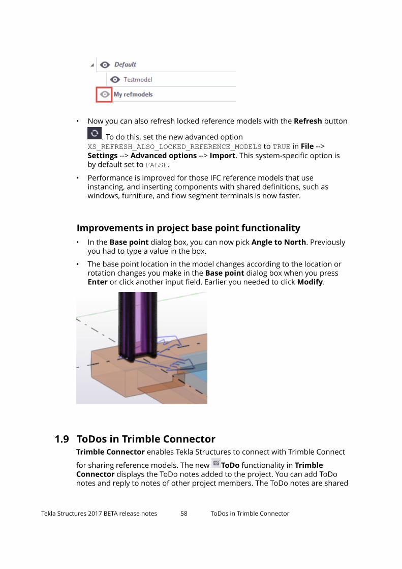
Improvements in project base point functionality• In the Base point dialog box, you can now pick Angle to North. Previously
you had to type a value in the box.
• The base point location in the model changes according to the location orrotation changes you make in the Base point dialog box when you pressEnter or click another input field. Earlier you needed to click Modify.
1.9 ToDos in Trimble ConnectorTrimble Connector enables Tekla Structures to connect with Trimble Connect
for sharing reference models. The new ToDo functionality in TrimbleConnector displays the ToDo notes added to the project. You can add ToDonotes and reply to notes of other project members. The ToDo notes are shared
Tekla Structures 2017 BETA release notes 58 ToDos in Trimble Connector

to all project members by default, but you can select a user or a user groupwho to assign the ToDo with a due date when it needs to be resolved.
• To display a list of ToDo notes, click the ToDo button in TrimbleConnector. You need to open a project to show the ToDos for the project.
• You can:
• Sort the ToDo list: Select to sort by Author, Assignee, Due date,Status, or Priority.
• Search for ToDo notes: Use Search to search for specific ToDos.
• Group ToDo notes: Select to group by Author, Status, Priority,Creation date, or Last modified date.
• View a ToDo: Double-click the ToDo in the ToDo list.
• Create a ToDo: Click the Create ToDo button. To create a ToDowith a view and a snapshot, select the native Tekla Structures objectsbefore clicking the command.
• Comment a ToDo: Double-clicking the ToDo note and add yourcomments in the in the opened property pane.
• Assign a ToDo: Double-click the ToDo note you want to assign, and clickthe Edit button. In the Assignee box, click Select and select a projectmember or user group from the list, or start typing the name of theuser or user group to filter the user list. Select the due date from thecalendar, and add priority and status if applicable.
• Synchronize ToDo notes: If another project member has created orcommented ToDo notes in Trimble Connector, the ToDos are
Tekla Structures 2017 BETA release notes 59 ToDos in Trimble Connector

automatically synchronized immediately. Alternatively, you can click the
synchronize button to synchronize the ToDos immediately.
• Adjust ToDo settings: Click the Settings button. The settings affectthe snapshots view.
1.10 NC export improvementsTekla Structures 2017 introduces a couple of improvements in pop-marks andNC file settings.
New option allowing pop-marks for parts welded on siteThe Pop-mark Settings dialog box now has a new option Add pop marks toparts welded on site that allows you to create pop-marks for parts that arewelded on site.
Pop-marks created based on the weld primary andsecondary partPreviously, pop-marks were created based on the assembly main andsecondary parts. Now the pop-marks are created based on the weld primaryand secondary part.
Maximum diameter for circular cuts to be drilledIn NC file export, circular part cuts are now written as holes if the diameter ofthe cut is less than the value defined for the new setting Maximum diameterfor circular cuts to be drilled in the NC file settings dialog box. Smallerinternal circular cuts are converted to holes.
1.11 Applications & components catalog and componentimprovementsTekla Structures 2017 introduces the following improvements in theApplications & components catalog and components.
Tekla Structures 2017 BETA release notes 60 NC export improvements

Change the order of groups in the Applications &components catalogYou can change the order of the predefined groups in the Applications &components catalog.
You can control the order of the groups with a sort index that is available foreach predefined group.
You can change the sort index by entering either a negative or a positiveinteger number, or 0, in the Sort index option box. A negative sort indexmoves a group towards the top and a positive sort index moves a grouptowards the bottom in the predefined groups section. Enter 0 or clear thevalue to revert to the default order. By default, the groups are in alphabeticalorder.Sort indexes are saved in the catalog definition files.
Concrete components
Wall layout tools
Wall layout tools support the design process from conceptual design todetailing wall structures. You can use the tools to:
1. Build a shape.
2. Build a shape and create openings.
3. Create wall type definitions.
4. Create wall elementation and define detailed wall geometry.
5. Define detailed connections, openings, embeds, and reinforcement.
Tekla Structures 2017 BETA release notes 61 Applications & components catalog andcomponent improvements

Wall layout tools is a set of components that you can use for creating andmodifying all common types of concrete walls, such as solid precast panelsfrom single layers to double walls and sandwich walls, and different wallstructures that are cast on the site. The wall structure may contain severallayers, for example, structural layers, insulation, void, and surface treatments.You can use direct modification to flexibly change the wall geometry, layeroffsets, openings and seam lines.
Wall layout tools are available in the Applications & components catalog.
Detailing manager
Detailing manager is used to apply detailing components into any structure.With Detailing manager you can define rules to apply multiple componentsat one go to detail the structure of a cast unit or the entire model.
1.12 New template attributesTekla Structures 2017 introduces some new features and improvements intemplates and reports, including new attributes for getting information ondrawings marked ready for issuing, and new attributes for reinforcement.
New attributes for getting information on marked readyfor issuing status
IS_READY_FOR_ISSUE
The IS_READY_FOR_ISSUE attribute tells if the drawing has been markedready for issuing in the Drawing list. This attribute can be used for addinginformation about drawings marked for issuing in drawing reports. The reportreturns the value 1 if the drawing is marked ready for issuing, and 0 if it is notmarked ready for issuing.
The Drawing list has a column Ready for issuing for this information. If thedrawing has been marked, there is a check mark in the column.
To include in the report who has marked the drawing ready for issuing, use theattribute READY_FOR_ISSUE_BY.
READY_FOR_ISSUE_BY
The READY_FOR_ISSUE_BY attribute tells who has marked a drawing ready forissuing. This attribute can be used for adding information about who marked
Tekla Structures 2017 BETA release notes 62 New template attributes

the drawing ready for issuing in drawing reports. The Drawing list has acolumn Ready for issuing by for this information.
To include in a report whether the drawing has been marked ready for issuing,use the attribute IS_READY_FOR_ISSUE.
New attributes for reinforcementThe new attributes USAGE and USAGE_VALUE show if a reinforcing bar is amain bar, or a tie or stirrup.
The USAGE attribute returns Main bar for main bars, and Tie or stirrupfor ties and stirrups. If the type of use cannot be defined, the USAGE attributereturns a blank value.
The USAGE_VALUE attribute returns 1 for main bars, and 2 for ties andstirrups. If the type of use cannot be defined, the USAGE_VALUE attributereturns 0.
1.13 New and deleted advanced optionsSome advanced options have been added and changed in and deleted fromTekla Structures
New advanced options
XS_MODEL_BACKUP_DIRECTORY
You can now define a folder for the backup copies of Tekla Structures modelfiles. The default value is ..\TeklaStructuresModels\backup\.
XS_REFRESH_ALSO_LOCKED_REFERENCE_MODELS
Now you can also refresh locked reference models with the Refresh button
. To do this, set the new advanced option XS_REFRESH_ALSO_LOCKED_REFERENCE_MODELS to TRUE in File --> Settings--> Advanced options --> Import. This system-specific option is by default setto FALSE.
XS_REPORT_BOLTS_WITH_SUPPORTING_MEMBER
You can now set the site bolts to the supporting member in reports and KSS bysetting the new user-specific advanced option XS_REPORT_BOLTS_WITH_SUPPORTING_MEMBER to TRUE in File --> Settings --> Advanced options --> Templates and Symbols. With this new advancedoption you are now able to show the field bolts in the BOM of the supportingmember. The default value is FALSE.
Tekla Structures 2017 BETA release notes 63 New and deleted advanced options

Examples
In the following BOM example, the advanced option is set to TRUE:
In the following BOM example, the advanced option is set to FALSE:
In the following KSS file example, the advanced option is set to TRUE:
In the following KSS file example, the advanced option is set to FALSE:
Deleted advanced options
XS_ENABLE_AUTODRAWINGS_IN_MENU
The advanced option XS_ENABLE_AUTODRAWINGS_IN_MENU is no longerneeded, and has been removed. It used to add the AutoDrawings commandon the Tekla Structures menu in some earlier Tekla Structures versions. TheAutoDrawings command is now available through Quick Launch. When youenter the command, the AutoDrawings dialog box is displayed.
Tekla Structures 2017 BETA release notes 64 New and deleted advanced options

XS_AD_PLATE_MESH_CHECK_DISTANCE_LIMIT andXS_AD_PLATE_MESH_CHECK_PART_ID
The advanced options XS_AD_PLATE_MESH_CHECK_DISTANCE_LIMIT and XS_AD_PLATE_MESH_CHECK_PART_ID have been removed from TeklaStructures.
Tekla Structures 2017 BETA release notes 65 New and deleted advanced options

2 Disclaimer
© 2016 Trimble Solutions Corporation and its licensors. All rights reserved.
This Software Manual has been developed for use with the referencedSoftware. Use of the Software, and use of this Software Manual are governedby a License Agreement. Among other provisions, the License Agreement setscertain warranties for the Software and this Manual, disclaims otherwarranties, limits recoverable damages, defines permitted uses of theSoftware, and determines whether you are an authorized user of the Software.All information set forth in this manual is provided with the warranty set forthin the License Agreement. Please refer to the License Agreement for importantobligations and applicable limitations and restrictions on your rights. Trimbledoes not guarantee that the text is free of technical inaccuracies ortypographical errors. Trimble reserves the right to make changes andadditions to this manual due to changes in the software or otherwise.
In addition, this Software Manual is protected by copyright law and byinternational treaties. Unauthorized reproduction, display, modification, ordistribution of this Manual, or any portion of it, may result in severe civil andcriminal penalties, and will be prosecuted to the full extent permitted by law.
Tekla, Tekla Structures, Tekla BIMsight, BIMsight, Tekla Civil, Tedds, Solve,Fastrak and Orion are either registered trademarks or trademarks of TrimbleSolutions Corporation in the European Union, the United States, and/or othercountries. More about Trimble Solutions trademarks: http://www.tekla.com/tekla-trademarks. Trimble is a registered trademark or trademark of TrimbleNavigation Limited in the European Union, in the United States and/or othercountries. More about Trimble trademarks: http://www.trimble.com/trademarks.aspx. Other product and company names mentioned in thisManual are or may be trademarks of their respective owners. By referring to athird-party product or brand, Trimble does not intend to suggest an affiliationwith or endorsement by such third party and disclaims any such affiliation orendorsement, except where otherwise expressly stated.
Portions of this software:
Open Cascade Express Mesh © 2015, by OPEN CASCADE S.A.S. All rightsreserved.
Disclaimer 66 New and deleted advanced options

D-Cubed 2D DCM © 2010 Siemens Industry Software Limited. All rightsreserved.
PolyBoolean C++ Library © 2001-2012 Complex A5 Co. Ltd. All rights reserved.
EPM toolkit © 1995-2006 Jotne EPM Technology a.s., Oslo, Norway. All rightsreserved.
FLY SDK - CAD SDK © 2012 VisualIntegrity™. All rights reserved.
Teigha © 2002-2015, Open Design Alliance. All rights reserved.
FlexNet © 2003-2015 Flexera Software LLC. All rights reserved.
This product contains proprietary and confidential technology, informationand creative works owned by Flexera Software LLC and its licensors, if any. Anyuse, copying, publication, distribution, display, modification, or transmission ofsuch technology in whole or in part in any form or by any means without theprior express written permission of Flexera Software LLC is strictly prohibited.Except where expressly provided by Flexera Software LLC in writing,possession of this technology shall not be construed to confer any license orrights under any Flexera Software LLC intellectual property rights, whether byestoppel, implication, or otherwise.
To see the third party open source software licenses, go to Tekla Structures,click File menu --> Help --> About Tekla Structures and then click the 3rdparty licenses option.
The elements of the software described in this Manual are protected byseveral patents and possibly pending patent applications in the United Statesand/or other countries. For more information go to page http://www.tekla.com/tekla-patents.
Disclaimer 67 New and deleted advanced options

Disclaimer 68 New and deleted advanced options

Index
Rrelease notes................................................... 5
69

70