telephone cable testing - blunham
TRANSCRIPT

[COPYRIGHT REGISTERED.] No. 138.
THE INSTITUTION OF
POST OFFICE ELECTRICAL ENGINEERS
Telephone Cable Testing (including Fault Localisation).
BY
W. T. PALMER, B.Sc., Wh. Ex., A.M.I.E.E.,
and E. H. JOLLEY, A.M.I.E.E.
A PAPER
Read before the London Centre on loth November, 1931,
and at other dates at the following Local Centres:— South Western; South Midland; North Western
and Eastern.
No. 138
THE INSTITUTION OF
POST OFFICE ELECTRICAL ENGINEERS.
Telephone Cable Testing (Including Fault Localisation)
By
W. T. PALMER, B.Sc., Wh. Ex., A.M.I.E.E.,
and E. H. JOLLEY, A.M.I.E.E.
A PAPER
Read before the London Centre on loth November, 1931,,
and at other dates at the following Local Centres:— South Western; South Midland; North Western
and Eastern.
TELEPHONE CABLE TESTING (Including Fault Localisation)
SYNOPSIS.
The paper is divided into three parts :—
Part I. Deals with underground cables—tests required in the factory and during subsequent installation work and end-to-end or final tests—includes leakance measurements—laying and balancing tests—capacity unbalance measure-ment by direct method—groups of loading sections—non-repeatered and repeatered cables—near-end and distant-end cross-talk measurement—variation of cross-talk with fre-quency, length and type of circuit—impedance frequency and impedance unbalance tests—visual methods of measuring cross-talk, etc.—attenuation and impedance tests on music circuits.
Part II. Classification of cable faults and localisation tests applicable—includes D.C. and A.C. methods—double-endAl tests—ballistic tests—method of mixtures—overlap—open and closed tests—slide-wire A.C. tests—Steven's test for C.R. faults—split pairs—split loading coils—obscure loading coil faults (short-circuited turns, etc.)—zero reactance test—cross-talk frequency methods.
Part III. Deals with submarine cables—lead-sheathed and balata cables—factory tests—laying and final tests—fault localisation and repair operations—Mance, Kennelly tests, etc.
Note.—The small index numbers in brackets shown thus :—(1), (2), etc., are reference numbers which are listed at the end of the paper.
INTRODUCTION.
With the continued increase in both importance and volume of international and inter-urban telephone traffic, the trunk and toll cable networks are playing. a more and more important part in the telephone system, and there is no need to emphasize the importance of the cable testing work which is necessary to secure (and subsequently to maintain) the high grade of transmission efficiency which is demanded. The

4
TELEPHONE CABLE TESTING.
progressive improvements and refinements in telephone cable manufacture have necessitated corresponding developments of the testing operations, and it is part of the purpose of this paper to outline such developments. The cable testing methods used in the Department are surveyed and it is hoped that such a general review of the subject will not be without interest and value. Some of the more important test results are analysed and discussed, but space does not permit of every phase being investigated in detail, and references are generally given where a fuller description can be found. Certain cases are dealt with fully where technical research and development have enabled hitherto " standard " and/or relatively slow methods to be replaced by quicker and more satisfactory methods.
The paper is subdivided as follows :— Part I. (A) Tests during manufacture.
(B) Tests during installation. (C) Tests subsequent to installation.
Part II. Fault Localisation Tests. Part III. Submarine Cable Tests.
PART I. (A).
TESTS DURING MANUFACTURE.
The following non-electrical tests are carried out before completion of the factory lengths in the case of twin (ordinary, composite, distribution and aerial), multiple twin (P.C.M.T.) and star quad (P.C.S.0.) types of paper core cable. All the necessary conditions to ensure that the completed cable shall be satisfactory are reflected in the detailed requirements of the P.O. Engineering Department's Cable Specifications :—
(1) Conductors.
These are visually examined for smoothness and all wires having a rough surface are rejected. By means of a micro-meter gauge the uniformity of diameter is examined at various points along the wire and if any appreciable difference is noted the wire is rejected. Joints are only permitted when a break occurs during the stranding process and must then be scarfed and soldered or welded for conductors over zo lb. gauge, and made in the presence of the Department's Inspect-ing Officer.

TELEPHONE CABLE TESTING. 5
(2) Insulating Paper. The paper is measured for uniformity of thickness and
is carefully examined for uniformity of texture and freedom from impurities. The breaking weight of the paper should exceed 4 lbs. for each inch width and o.00i inch thickness.
(3) Stranding. The colour scheme and the direction of the lays are
examined to see if they agree with the relevant specification. When the length is completed the ends of the cable are opened and immersed in molten paraffin wax. The follow-ing further tests are then made :—
(4) Insulated Conductor. The insulating paper is tested for brittleness periodically
by wrapping an unwaxed insulated conductor round a pencil. If satisfactory the paper should not split when subjected to this treatment.
(5) Lead Sheath. This is examined for mechanical defects and samples are
periodically submitted for chemical analysis. The maximum diameter is measured with a micrometer caliper, care being taken to ensure that the diameter measured is the maximum in each case since the sheath may be oval. On a percentage of the lengths pressure tests are taken.
Electrical tests on the manufactured lengths are made to ascertain how far the pair and phantom circuits are satisfac-tory from a purely transmission point of view. These are :—Conductor resistance, dielectric resistance (both A.C. and D.C.) and mutual capacity. Measurements are also made of resistance unbalance, capacity unbalance, and in the case of continuously loaded cables, inductance unbalance, to deter-mine how far the circuits are satisfactory from the interference point of view.
(i) Insulation Resistance. The wires are grouped so that every wire is tested against
all adjacent wires and the lead sheath. In the case of twin cables, the " A ' wires of alternate pairs in alternate layers are bunched to form a group, and similarly the " B " wires.

6 TELEPHONE CABLE TESTING.
The other pairs are similarly treated. This gives 8 main groups. Pairs which are not so included are separately grouped. Each group is then tested against all other groups and sheath. In the case of P.C.S.Q. and P.C.M.T. cables, the A, B, C, and D wires of the quads are first bunched together throughout the cable to give four groups and each group is tested against the other three and sheath. Then the four wires of alternate quads and alternate layers are grouped and tests made on each group against the remainder and sheath.
The test is made with a galvanometer of the reflecting mirror type, the battery voltage is 300, and the galvanometer deflection is compared with that obtained when a standard megohm is substituted for the circuit under test.
(2) Mutual Electric Capacity (M.E.C.). This test can be taken when the cable is wired up in
groups for the insulation resistance test, in the case of twin cables. The capacity can be measured between the A's and the B's bunched of each layer or between the whole of the A's in the cable bunched and the whole of the B's bunched. In the case of the composite twin cables the groups having different specified capacities are measured independently. P.C.S.Q. and P.C.M.T. cables (generally) have each pair circuit measured separately.
The testing circuit is a simple form of Max. Wien bridge.
(3) Conductor Resistance (R). At least one pair in each layer and from 20 to 30 pairs in
all (depending on the size of the cable) are connected in series for the test. In the case of composite cables at least to pairs of each size of conductor are measured.
The test is made with a 4-dial Wheatstone Bridge. A correction to R must be made (i) for the lead resist-
ance, (ii) for the temperature.
(4) D.C. Resistance Unbalance. This test is one for readily obtaining the difference in
resistance between the A and B wires of a pair, expressed as a percentage of the total loop resistance.
The testing circuit is arranged so that the unbalance can be read directly from a graduated scale as a percentage of the

TELEPHONE CABLE TESTING. 7
loop resistance.0) The tests are only carried out in the case of main underground cables.
(5) Capacity Unbalance.
This test is made in the case of P.C.M.T. and P.C.S.Q. cables to determine the inequalities of wire-to-wire and wire-to-earth capacities. These inequalities (which form the principal cause of cross-talk) are usually expressed in micro-micro-farads.
The testing circuit is generally some form of A.C. capacity bridge.
The measurement of capacity unbalance is considered later in connection with installation tests.
(0) Leakance.
Leakance is the reciprocal of the effective resistance of the dielectric and is denoted by G. The ratio G/C, i.e., Leakance Capacity, is referred to as the Leakance Con- stant. As the power factor for paper core cable dielectric is so small the ratio G/wC gives the value of the power factor nearly enough for all practical purposes. At Soo p.p.s. the power factor of the air spaced paper core dielectric of a typical underground cable is about .003 (G/C = 15), for a solid paper core submarine cable it is about .005 (G/C = 25), while for submarine cable having gutta percha or balata as dielectric it varies from about .02 to .0 (G /C = too to 5o).
Of recent years submarine synthetic dielectrics have been manufactured with the ratio G/C as low as 7, for example, paragutta, a dielectric which has been proposed for the Trans-Atlantic Telephone Cable.
Despite such low values of leakance, however, it is important that its value should be accurately determined during the process of manufacture and this has been made more necessary since the adoption of ink line markings on the paper for identification purposes. It has been found that unless the ink has been carefully chosen it can introduce con-siderable losses in the dielectric. On account of the low value of the leakance in relation to the other primary con-stants, its accurate measurement is attended by some difficulty. In the first place, to secure accuracy and to avoid the necessity of corrections on account of the resistance of the wires, the measurement must be made on short lengths of cable, e.g., in

8 TELEPHONE CABLE TESTING.
the case of underground telephone cables the measurements are made on lengths of about 200 yards and, in the case of submarine cables, on lengths of about 6o feet. Measure-ments at one frequency only need be made in a routine test, usually at Soo p.p.s., on a small percentage of factory lengths of each cable.
There are several methods of carrying out the necessary tests and they all include elaborate attempts to overcome the difficulties particular to the problem. The testing set described below has been used in recent experimental work on submarine cable cores. It is a set which avoids the use of very expensive high-grade condensers having extremely low power factors which are necessary in certain methods. It pro-vides an accurate and rapid means of determining the leak-ance constant and is therefore particularly suitable for routine factory tests. Since it is usual to refer to the ratio G/C in dealing with dielectric properties, the set is referred to as a " G/C Bridge."
G/C Bridge. Fig. I shows the principle of the method of measurement. The unknown admittance is connected to points B and C.
FIG. I.
P, P, and Q, Q, are non-reactive fixed resistances. K is an adjustable condenser. R is a non-reactive adjustable resistance. Balance is secured by the adjustment of K and R and
the conditions for balance are as follows :—
C = K (I)

TELEPHONE CABLE TESTING. 9
GR
(2) Q(Q + R)
It will be seen that, if R is very small compared with Q, (2) may be written :—
G =
In practice, Q is made equal to io,000 ohms (and, so long as R is not greater than about ioo ohms, the foregoing approximation is sufficiently accurate for practical purposes)
and hence G in micromhos is given by loo
The simple form of bridge shown in Fig. I is, however, not suitable for the accurate measurement of the low leakance values met with in telephone cables. In the first place it necessitates an accurate calibration of the power factor of the standard condenser, (K), or, alternatively, the use of a very costly high-grade condenser, such as an air condenser using silica-quartz mountings, of which the power factor may be neglected. Errors are also introduced
(I) by inequalities in the values and distribution of the capacity couplings and leakance paths between the components themselves and earth, and
(2) by inequalities in the reactive components of the resistances, which would be quite negligible under general A.C. testing conditions.
Errors due to (I) can be eliminated by an elaborate system of screening as shown in Fig. 2, which also enables the equalising to earth of the points B and C to which the unknown admittance is connected.(2)
Referring to Fig. 2 it will be seen that all the components, including the secondary windings of the transformers, in the supply and detector circuits, have an inner screen which is connected to one end of the component. This ensures that all capacity and leakance paths from the component terminate at some definite point. In the case of the ',ow ohm ratio-arms this is point A of the bridge. For the io,000 ohm and adjustable resistances, the secondary of the input transformer and the two condensers KJ and K2, this point is B. The inner screen on the detector transformer secondary is con-nected to C and is continued from the transformer to point D of the bridge and its associated connections. This ensures
R

I0 TELEPHONE CABLE TESTING.
Detector
.----- -3211.0.012.4------
Double Screen Transform
Unknown Admittance.
1. ,...••••=111 0 Earthed Screen
FIG. 2.
that point D shall only have capacity or leakance to point C and, as this will be in parallel with the detector circuit, it will not affect the balance of the bridge. Similarly, the inner screen on the input transformer secondary is continued from the transformer to point A of the bridge and its associated connections, which in this case include the inner screens of the ',ow ohm resistances. This ensures that point A of the bridge shall only have capacity and leakance to point B and as this will be in parallel with the source it will not affect the balance of the bridge. The residual capacities and leakances of the bridge are by this means located to points B and C and it only remains to fix these values, subsequently taking account of them by means of an initial balance of the bridge.

TELEPHONE CABLE TESTING. II
The method adopted is to enclose the components of the bridge in earthed screens, or to enclose the whole of the bridge in a single earthed metal screening box. It will be seen that the use of double-screened transformers is involved and these prevent any unbalance to earth of the source and detector circuits from affecting the balance of the bridge. With the completion of the screening of the bridge, points B and C only have admittance to one another and to earth. The method of connecting up the screens, however, ensures that the capacity of B to earth is greater than that of C to earth and it is therefore a simple matter to increase the capacity of C to earth by the addition of a condenser, as shown, and thus make it equal to that of B. This equality is a matter of importance when the bridge is used for measure-ments of admittances, such as that of a cable pair, which are essentially- balanced to earth and should remain so during the measurement.
Errors due to (2), i.e., differences between the reactive components of the ',pop-ohm and io,poo-ohm resistances, are overcome by a method due to Dr. L. G. Brazier, which also avoids the necessity for the use of a standard condenser of known or negligible power factor.(3) According to this method, a fixed condenser, having a capacity somewhat greater than the maximum value of capacity which it is re-quired to measure, is connected across the arm BD of the bridge, and a variable condenser, having a maximum capacity equal to that of the fixed condenser, is connected across the arm BC. When the admittance to be measured is connected to the points B and C, the bridge is balanced by reducing the capacity of the variable condenser by an amount equal to the unknown capacity, and increasing the value of the resistance by an amount R until the total admittance between the points B and C is the same as before. The bridge solution already given holds also in this case, viz. :—
R = G (in micromhos).
'Po The total admittance of each of the bridge arms remains
unaltered and the method is thus essentially one of substitu-tion and errors due to the aforementioned inequalities are eliminated.
The leakance of the condensers used does not require to be known, since this is taken into account in the initial balance of the bridge. All that is of importance in this con-

12 TELEPHONE CABLE TESTING.
nection is that the leakance of the variable condenser should not vary with change of setting of the condenser. This con-dition is sufficiently fulfilled by the use of well designed continuously variable air condensers in which the only losses of importance are those in the solid dielectric used in the mounting of the plates, which losses in recently constructed condensers are essentially constant for all settings of the condenser. With the bridge used in the experiments, the change of leakance of the variable condenser, for a given change of capacity, is less than the leakance of a silica-quartz air condenser of corresponding capacity, which is itself less than can be measured by any known means of calibrating such condensers and is therefore negligible for all practical purposes.
A G/C bridge was constructed on the above plan for the Department by Messrs. Gambrell.
Constancy of calibration of the bridge with reasonable constancy of temperature has been secured by placing the whole of the components in a well constructed case and Fig. 3 is an external view of the complete instrument.
EXTERNAL VIEW OF G/C BRIDGE. FIG. 3. "
Admittances having a capacity up to 14,000 µµF and leakance up to 11.i micromhos can be measured and, by using
TELEPHONE CABLE TESTING. 13
an amplifier and telephone receiver in the detector circuit, a sensitivity of o.00t micromhos can be secured with an accuracy of 1% which is well within the limit demanded by practical considerations. The bridge can be used over a range of frequencies from 30o to 9,000 p.p.s. For tests above 3,000 p.p.s., in place of a telephone receiver an amplifier-rectifier and a sensitive D.C. galvanometer have been used in the bridge detector circuit.
PART I. (B).
TESTS DURING INSTALLATION.
(t) Laying and Balancing Tests. Telephone cables are subjected to electrical tests during
all stages of the laying operations. In their simplest form these tests are merely : —
(a) For continuity and freedom from earth or contact. (b) To prove absence of crosses. (c) To ascertain insulation resistance. (d) To ascertain conductor resistance. (e) To prove absence of overhearing.
Tests (a) and (b) are made with a battery and lineman's detector ; (c) with a megger ; (d) with a Wheatstone bridge ; and (e) with a buzzer or telephone as the source of disturbance, disturbing on individual or bunched pairs and listening on other pairs with an ordinary telephone.
In the case of toll and the more important loaded junction cables these tests are supplemented by capacity unbalance and cross-talk measurements on loading sections. Recent ex-perimental work has been carried out in connection with aerial cable, using to lb. conductors, systematically jointed* (i.e., no capacity balancing in the field), coil loaded, and worked " four-wire " with the object of using such repeatered cables for toll circuits instead of 4o lb. or 7o lb. non-repeatered loaded underground cables, as at present used. With aerial cables worked in this manner the amount of testing required during installation is considerably reduced, consisting
. Systematic jointing is a method by which pairs or quads are crossed at the joints in accordance with a predetermined sequence to reduce as far as possible the length over which any two circuits will be adjacent through-out the cable and was introduced in 1926 for use in loaded twin cables.
14
TELEPHONE CABLE TESTING.
essentially of insulation and conductor resistance and cross-talk tests on completion.(')
The tests imposed during the laying of main trunk under-ground cables are as follows :—
(a) Insulation Resistance. (b) Conductor Resistance and Conductor Resistance
Unbalance. (c) Capacity Unbalance. (d) Cross-talk (terminated). (e) Mutual Electric Capacity.
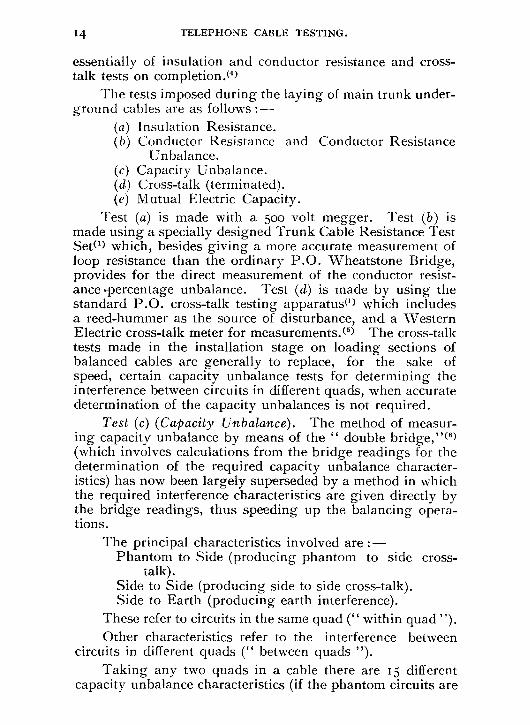
Test (a) is made with a 50o volt megger. Test (b) is made using a specially designed Trunk Cable Resistance Test Set(') which, besides giving a more accurate measurement of loop resistance than the ordinary P.O. Wheatstone Bridge, provides for the direct measurement of the conductor resist-ance percentage unbalance. Test (d) is made by using the standard P.O. cross-talk testing apparatus(1) which includes a reed-hummer as the source of disturbance, and a Western Electric cross-talk meter for measurements.(5) The cross-talk tests made in the installation stage on loading sections of balanced cables are generally to replace, for the sake of speed, certain capacity unbalance tests for determining the interference between circuits in different quads, when accurate determination of the capacity unbalances is not required.
Test (c) (Capacity Unbalance). The method of measur-ing capacity unbalance by means of the " double bridge,"19 (which involves calculations from the bridge readings for the determination of the required capacity unbalance character-istics) has now been largely superseded by a method in which the required interference characteristics are given directly by the bridge readings, thus speeding up the balancing opera-tions.
The principal characteristics involved are :— Phantom to Side (producing phantom to side cross-
talk). Side to Side (producing side to side cross-talk). Side to Earth (producing earth interference).
These refer to circuits in the same quad (" within quad "). Other characteristics refer to the interference between
circuits in different quads (" between quads "). Taking any two quads in a cable there are 15 different
capacity unbalance characteristics (if the phantom circuits are
RING SUPPLY EARTH
00 00 0
-0 0 0 -0 0
<1 0
00 0 0 0 0 =0=. 00 —
TEL.
RING SUPPLY EARTH 00 00 0
FIG. 4.
A. B. C.
DI
A2
82 Cl
DI
TELEPHONE CABLE TESTING. 15
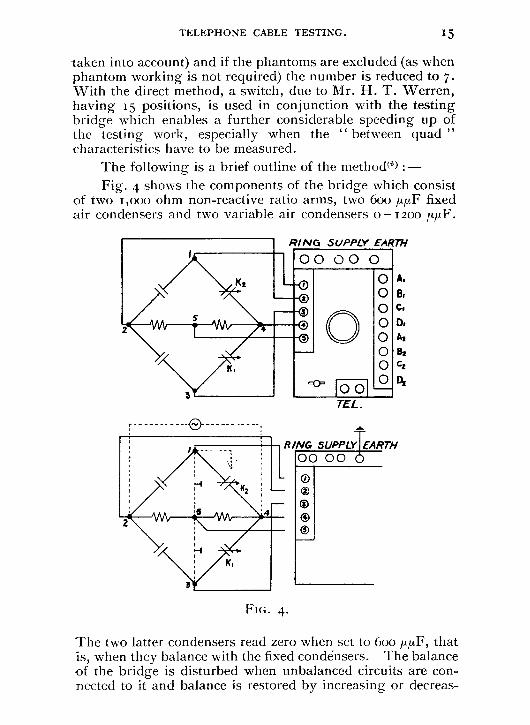
taken into account) and if the phantoms are excluded (as when phantom working is not required) the number is reduced to 7. With the direct method, a switch, due to Mr. H. T. Werren, having 15 positions, is used in conjunction with the testing bridge which enables a further considerable speeding up of the testing work, especially when the " between quad " characteristics have to be measured.
The following is a brief outline of the method(6) :—
Fig. 4 shows the components of the bridge which consist of two 1 ,000 ohm non-reactive ratio arms, two 600 µIII' fixed air condensers and two variable air condensers 0 —1200 ,upF.
The two latter condensers read zero when set to 600 ,up,F, that is, when they balance with the fixed condensers. The balance of the bridge is disturbed when unbalanced circuits are con-nected to it and balance is restored by increasing or decreas-

vi—x=p z — y=q
ral — Z = r x—y=s a —b=u c — d=v
(a)
(b)
B
i6
TELEPHONE CABLE TESTING.
ing the capacity of the variable air condensers. The dotted connections in the lower figure are used for initially balancing the bridge when the scales of the condensers are adjusted to allow for slight inaccuracies in the bridge components.
In Fig. 5(a) the capacity network of a cable quad is shown and the usual nomenclature of direct capacities w, x, y, z, a, b, c, d, m, it, is used, while Fig. 5(b) shows the net-work reduced to an equivalent 6-branch network by applying the " Network " or " Star-Mesh " transformation theorem.(") When the capacity network is considered in this form the measurement of the various capacity unbalance characteristics by the direct means can be easily followed.
CAPACITY NETWORK.
FIG. 5.
Fig. 6 shows how the wires are connected to the bridge for the measurement of the phantom to side, side to side and side to earth characteristics and the resulting disposition of the cable capacities. Considering the phantom to side case it will be seen that the source is across one side circuit (AB) and the telephone is, in effect, connected across the phantom circuit. Then the condition for silence in the telephone will be seen to be :—
k, — Ki = (w — x) + (7, — Y) ± a+b+c+d (a — b)(c + d)

Phantom Side,
TELEPHONE CABLE TESTING. 17
Side Side
Side Earth
FIG. 6.
which may be written
k i — K1 =p+q+?1U
-where p, q, u have the values shown in Fig. 5 and a ---->- b — - > - - c d
The reading on condenser K„ therefore, gives the value
p + q + u

18 TELEPHONE CABLE TESTING.
which is known as the phantom to side interference character-istic. Condenser K2 is used for what may be termed a power factor adjustment.
Similarly, the side to side interference characteristic can be measured directly by K,, as shown in Fig. 6, K, being first set to read zero so as to balance k1. This gives
k, — K, = (w — x) — (a-- b)(c — d)
(z y) a+b+c+ d
i.e. , k, — K, p - q.
(a+
— b
b)(+
c — c
+d d .
neglecting
The reading on the condenser a
K1, therefore, gives the value
P - q
which is known as the side to side interference characteristic.
Referring to the side to earth case it will be seen that a considerable capacity is thrown in parallel with the ratio arms, namely, w + z in one case and x + y in the other. The difference of these two expressions is p + q. When testing on jointed lengths of cable, if the circuit under test has been balanced for phantom working, p + q will not be large; and the presence of the capacities mentioned, in parallel with the ratio arms, will not as a rule lead to any difficulty. If, how-ever, the cable has not been specially balanced for phantom working, p + q may be fairly large, and some difficulty may be experienced in obtaining a satisfactory balance, especially on the longer lengths of cable. In addition, the irregular dis-tribution of the (p + q) unbalances will give errors in the value obtained for the characteristic, for which it is not possible to allow. In the case of lengths of cable of more than 2,000 yards it has hitherto generally been the practice, (when the cable has not been balanced for phantom working) to rearrange the components of the bridge and measure the side to earth characteristics in the standard double bridge method, but another method by which the error can be avoided has been suggested by Mr. Hodge of the Research Section. Fig. 7 refers.
An additional switch S is included in the testing circuit as shown in Fig. 7(a). With this switch at position i the testing conditions are normal. In order to measure the un-balance to earth of the AB side circuit (i.e., " u "), the

02
o5 Term
inals
on /
5 p
osl
Sw
/ic
h
TELEPHONE CABLE TESTING. IO
Bridge
/12
4 5
(a)
2 2
5
(b)
A CD a
FIG. 7.
phantom to side characteristic (p + q + u) is first measured as shown in Fig. 6, the value being given by the reading on K1. Switch S is now changed to position 3 when the arrange-ment of the bridge connections and cable wires is as shown in Fig. 7(b). Condenser K1 is left at the setting obtained in the previous measurement and balance secured by adjustment of K2. We now have the condition that :—
(k, - K,) + (k, - K,) =p+q+u
but k1 -K1 =p+q+111
k2 - K2 = u
and u is therefore given by twice the reading on condenser K2.
The unbalance to earth of the CD side circuit (i.e., v) is measured in a similar manner.
By this method the presence of unequal cable capacities in parallel with the ratio arms is avoided.
Fig. 8 shows the connections of the'bridge effected by the 15-position switch. The first 6 are for measurements in the same quad. The remaining 9 are not fundamentally different from those already given in connection with the side to side

20 TELEPHONE CABLE TESTING.
ARRANGEMENTS OF BRIDGE, FOR WITHIN AND BETWEEN QUAD
MEASUREMENTS, AS GIVEN BY I5 POSITION SWITCH.
C) * Side. 0 * [Side, 0 Side, Side,
8
C
ti
M
A 8
•
•
CD es.,
Power etor
0.11^6
D
•
AB r‘,..,
•
PF
C
M.
® Side, E 0 Sides E © 1-, IE
C . . ,-
r‘,
— R — M ..-.7 AB
PF
8
•
.
.
c\_,
A4
D PF.
D .
AB • PF
1%,
A4
© +4 1 4-a ® *, Pr3. 0 -ti IPr 4
Pr2
IN,
C
Da
Pr/ Pr 1
r•„,
Pr3
P r4
Pr/ Pr2
"._,
4k
82
Pr/
0 Prl +2 © PrE 1-2 @, Pr I 1 Pr 3
8,
41.,
A2
B2
A, ,
2\2
Pr3
Pr4
A, D,
^.2
Pr3
Pr4
C,
0 Pr! Pr4 49 PrE 1Pra a Pr2IPr4
0,
IN.,
Ca
D
C 0
e....,
A2
B2
C, B
Ca
Z:
A,
KEY Within quad Measurements Wires Circuits
A B
}side, 1
D C }Side.,
Between Quad Measurements uad, Quad2
Wires Circuits Wires Circuits
A Poe- I A2
C, D,
8, Port
B 2
C2 D2
)14:1,31
iPar4 ik
FIG. 8.
measurements, merely illustrating the order of connecting the circuits in different quads by the switch.

TELEPHONE CABLE TESTING. 21
Fig. 9 shows the switch itself which is of the barrel type, the springs on the left making contact with the strips on the drum.
FIG. 9.
Test (e) (Mutual Electric Capacity).(6) This test is carried out in the case of main cables which are required for repeatered circuits as, in order to ensure that the overall cable impedance frequency characteristics shall be sufficiently uniform, a high degree of uniformity of mutual capacity has to be maintained throughout the consecutive loading sections. A simple form of A.C. capacity bridge is used.
(2) Loading Tests. Loading Tests are those carried out during the pro-
gress of the work of joining in the loading coils. In the case of the less important cables the tests are only such as will ensure that crosses are not inserted at the loading points and that the insulation resistance of the cable is maintained at a satisfactory figure.
With the more important repeatered cables the tests are supplemented by cross-talk, conductor resistance, and induct-
22 TELEPHONE CABLE TESTING.
ance tests on groups of loading sections for the better check-ing of the cable and coils.(') Where the cable is not phantom-loaded it is divided into lengths containing up to twelve load-ing sections, for the purpose of making these tests. Where the cable is phantom-loaded, the first twelve loading sections from each end of the cable are further sub-divided into groups of three so that an improvement of the near-end cross-talk* between a phantom circuit and its associated side circuits can be secured by the introduction of suitable crosses in the cable quads when jointing the short lengths together. These crosses reduce the series unbalances (resistance and induct-ance) of the pairs concerned and the best combination is determined by trial during cross-talk tests, known as " Switch-ing Tests." Improvement of the near-end cross-talk due to capacity unbalance alone cannot be effected by such switching tests on loaded lengths of cable and thus side-to-side cross-talk cannot be materially changed by switching operations.
The typical cross-talk frequency curves given in Fig. io show a marked difference between that for near-end and that for distant-end cross-talk. The irregularity of the near-end characteristic is accounted for by the fact that the phase of the incoming voltage due to any particular unbalance depends upon the distance to that unbalance, and on the frequency of the disturbing current. The smoothness of the distant-end cross-talk curve is accounted for by the fact that the total phase change between the sending end of the disturbing circuit and the listening end of the disturbed circuit is essentially the same for all unbalances of the same type no matter where such unbalances occur, unless there is a con-siderable difference between the wave-length constants of the two circuits concerned. This fact permits of considerable reduction of the distant-end cross-talk due to all types of un-balance when switching together long lengths of cable. Switching tests for the reduction of distant-end cross-talk are therefore made when jointing lengths of cable equal to about a quarter of the repeater section concerned.
Continuously Loaded Cables are usually switched for reduction of cross-talk during laying operations, the cable being balanced in sections of about 4 miles.
* " Near-end " crosstalk is the crosstalk between two circuits when the source of disturbance and the listener are at the same end of the cable. " Distant-end " crosstalk is the crosstalk between the circuits when the disturbing current is sent into the cable at the end distant from the listener. See also reference (7).

1
300
VALKI4CAS1140 WITH i,80 sate-owoota,
70
1 • I , 1
I ; I i 1
1 1 t 1 I
D 400 800 — Floo 1600 row- 2400
FREQUENCY — PERIODS PER SECOND.
L
1911)
N. NIALle MEASURIO %ono
{0 80 REED WSW&
170
PA1Ri /4062 . ?STANT END CROSSTALK. t"—#1001
•
TELEPHONE CABLE TESTING. 23
DUNDEE-ABERDEEN CABLE.
CROSS-TALK V. FREQUENCY. TESTED AT ABERDEEN.
40 LB. CONDUCTORS LOADED WITH 120 MH. COILS AT
1.136 MILES SPACING.
FIG. 10.
In connection with the Insulation Resistance tests it should be mentioned that it is necessary to observe special precautions when testing on loaded pairs so as to limit the

24
TELEPHONE CABLE TESTING.
possibility of damage to loading coils by the sudden dis-charge of cable wires following on the occurrence of a spark-ing or intermittent contact during the progress of the test. In the grouping of the A, B, C and D wires, the quads are divided into groups to prevent heavy discharges. The grouping adopted for testing on actual cable lengths is such that not more than 30 wires are simultaneously connected to the live terminal of the megger. On longer lengths of cable the grouping is still further restricted and in end-to-end tests not more than to wires are connected simultaneously.
PART I. (C).
TESTS SUBSEQUENT TO INSTALLATION.
All the more important cables are subjected to final (end-to-end) tests which are made after the cables have been completely installed and terminated. These tests ensure that before a cable is brought into service, its electrical character-istics are satisfactory, and that no faults exist which might impair the efficient working of the cable, and which would otherwise pass undetected.
The cables which undergo final tests may for this purpose be divided into three classes, viz.
Non-loaded Junction Cables. 2. Non-repeatered Loaded Cables. 3. Main Repeatered Cables.
1. Non-loaded Junction Cables.
Since the introduction of star-quad cable for use in local junction cables a number of these cables have been included in those subjected to special final tests. The tests are carried out by a qualified District Testing Officer and the results submitted to Headquarters for scrutiny.
The tests made are as follows :— (i) Conductor resistance (loop and unbalance).
(ii) Insulation resistance. (iii) Cross-talk within quads (terminated).
The side-to-side and phantom-to-side cross-talk values are measured in every case, but only read-ings of too or over are recorded in the former and moo and over in the latter cases.
TELEPHONE CABLE TESTING. 25
(iv) Cross-talk between quads (terminated). About io°/<, of adjacent quads are tested for
pair-to-pair cross-talk and only values of ioo millionths and over are recorded.
The phantom-to-side cross-talk measurements are in-cluded, not because this cross-talk is important, since phantom circuits are not provided, but because such faults as contacts with wires not available at the testing point and split pairs between pairs in different quads are shown up by high phantom-to-side cross-talk in the quads concerned.
2. Non-repeatered Loaded Cables.
The final tests on these cables are carried out by a Head-quarters testing officer. The tests made are :—
(i) Conductor resistance (loop and unbalance). (ii) Insulation resistance.
(iii) Inductance. (iv) Cross-talk (terminated). (v) Speech (transmission) test.
Precautions, as described in connection with the loading tests, have to be observed during all insulation resistance tests.
3. Main Repeatered Cables.
The final tests made on main repeatered cables are necessarily more elaborate than those on other cables. This is due to the high standard of uniformity of impedance and immunity from interference demanded. When the whole work of laying, balancing and loading repeater sections of cable has been given out to contract the final tests constitute the acceptance tests of the installed system. For this reason the tests have to be somewhat more comprehensive than if the cable had been accepted loading section by loading section and subsequently loaded by the Department. Even in such cases as the latter it is highly desirable that adequate tests are made upon the completion of installation not only so that it is ensured that every circuit in the cable is satisfactory, but also for the securing of data for future technical and economical considerations.
A typical programme of final (end-to-end) tests for the

26 TELEPHONE CABLE TESTING.
acceptance of a modern repeatered cable is given below and it will be seen that a large amount of testing is involved. The exact amount of testing work in any specific case is, of course, dependent on the character of the results, and the testing programmes are frequently amplified or curtailed during the progress of the tests. The consideration of the speeding-up of the tests without detracting from their re-liability has led to improvements in this direction, so that a more comprehensive programme of tests than previously can now be completed in about one-third the time formerly required. In addition, it is possible for sufficient tests to be carried out within a fortnight to enable a repeater section of cable containing, say, 200 circuits, to be accepted. Some of the improvements which have made this possible are indicated in the discussion of the following testing programme :— Programme of Tests for the Acceptance of a Trunk Cable
(Repeater Section) Completely Installed by Contract. (i) Conductor resistance (loop and unbalance). (ii) Insulation resistance.
This test follows (i) to ensure that conductor resistance faults are not temporarily sealed and thus overlooked.
(iii) Cross-talk.
In the cases of cross-talk which are enumerated, the near-end values are measured at each end of the repeater section and the distant-end values measured at one end only :—
(a) All cases of side-to-side (within quad) are measured. (b) Each balancing group is taken separately and not
less than 20% of the total possible pair to pair combinations are measured in each group.
(c) Each screened pair (music circuit) is tested to all immediately adjacent screened and unscreened pairs.
(d) Each balancing group is tested to adjacent balanc-ing groups, not less than 20% of the total possible pair to pair combinations being tested.
(e) Each Go circuit is tested to at least one Return circuit and each Return to at least one Go. In all, at least 20% of the total possible combinations between Go and Return circuits are tested (distant-end measurements are not made in this case).
This programme of cross-talk tests refers to a cable in which the phantoms are not loaded. When the phantom

TELEPHONE CABLE TESTING. 27
circuits are loaded they are, of course, included in the cross-talk measurements.
(iv) Attenuation. (a) All loaded pairs at Boo and 2,400 p.p.s. (b) All loaded music circuits at 800, 2,400 and 7,000
p.p.s.
(v) Impedance Unbalance. All loaded circuits are tested from each end of the repeater
section throughout the specified frequency ranges.
(vi) Impedance Frequency Characteristics.
Circuits are selected on the results of the impedance un-balance tests and their impedance measured over a suitable frequency band. The circuits selected always include those giving the worst results in the impedance unbalance tests.
(vii) Cross-talk-Frequency Characteristics. Several cases of near-end and distant-end cross-talk are
selected and the cross-talk measured over a range of frequency from about 300 to 3,000 p.p.s. (Typical curves are shown in Fig. 1o).
(viii) Attenuation-Frequency Characteristics.
(a) One music circuit from too to 7,000 p.p.s. (b) One four-wire circuit from 300 to 3,000 p.p.s. for
each type of loading. (c) One two-wire circuit from 300 to 2,50o p.p.s. for
each type of loading.
(ix) Attenuation-Current Characteristics. A change of the electrical constants of a circuit with
change of current is indicated by a change of the measured attenuation. If such an effect is present in any degree it will lead to distortion of the transmitted signals, the attenuation of the circuit changing with the amplitude of the signals. In a coil loaded cable the only characteristic likely to be affected by change of current is the effective resistance of the loading coils due to increase of hysteresis losses with increase of current. Tests are made on a few representative circuits at several frequencies to determine the extent of this effect.

28 TELEPHONE CABLE TESTING.
Cross-talk Measurements on Trunk Cables.(8) Owing to the importance of cross-talk in repeatered cables
a large number of measurements have to be made and may amount to as many as 3000 in a large cable. Normally, the cross-talk is measured using a mixed tone as the source of disturbance, but values approaching or exceeding the specified limits are measured with speech as the disturbing source and the results so obtained are regarded as final. Each two circuits tested for cross-talk are tested in three ways, viz., (I) near-end cross-talk, at the " Up " station ; (2) near-end cross-talk at the " Down " station ; (3) distant-end cross-talk at only one of the two stations concerned.
With the ordinary form of cross-talk set these three measurements would involve three separate series of tests. To avoid this, and speed up the tests, a modified form of cross-talk set has been used which enables the three series of tests to be made at the same time, a set being connected at each end of the cable.
Fig. II gives a diagram of the set used and shows the wiring required when phantom and side circuits have to be considered. When side circuits only are concerned the wiring can be made somewhat less complicated.
These sets have been arranged so that they may, by the operation of keys, be used at one end of the cable under any of the following conditions :—
Near-end cross-talk measurements. Terminating cable circuits for the measurement of
cross-talk from the other end of the cable. Distant-end cross-talk measurements. Termination of cable circuits and supplying tone
for the measurement of distant-end cross-talk at the other end of the cable.
The 6 transformers and various resistances are to enable matched impedance conditions to be given under every con-dition of test.
A further speeding-up of the tests is secured by adhering to a pre-arranged order of testing, each station either taking measurements or giving suitable conditions for tests required by the other station.
The cross-talk meters in these sets are of a special form. The meter is on the lines of the Western Electric cross-talk meter and the range of cross-talk values covered is almost the
(I) (2)
(3) (4)

TELEPHONE CABLE TESTING. 29
01211.01. A 0 QUADZ.
0
TESTING Su FOR DISTANT- AND NEAR-END CROSSTALK MEASUREMENTS. 3 c D A 0 10.111.
0
rawc SO
21.0^ = 0,
Two- RA*44 CA0522-02(
MET Res ISTANGSS FoR
A DJUSTMENT OF SibgfroAt4TOH
ImPcoAma RATIO . %ANN ATIN4
5,572e4c25
IMi QvAD Z.
MA
Ira.
L,
METER CiftCwr AUgiLi ARV
ReSiSTANCEC
2 .3"
leo
••• RI
O
123 • "......***0"./ T002wATuo0 Dirro3300 It2SISTM1.3 SouoCe . fest gum.1,
SCREENED KEYS 1112 742
7n11.11PwOwg_ ...muter ou ANY FC333.1.040
FIG. II.

Range 2
2 Positron Switch
Range, I 64 On
Listen J
FIG. I2.
30 TELEPHONE CABLE TESTING.
same as with the ordinary meter. In this case, however, the total range is divided into 36 steps whereas in the Western Electric Meter there are only 20 steps. Further, the resist-ances between stops are of such a value as to enable the scale to be graduated in decibels in accordance with the modern method of expressing cross-talk as an attenuation. The actual number of stops on the instrument is 22 (including the zero stop), but a switch enables the transmission loss between the " talk " and " listen " terminals, for any particular setting, to be varied by 3o db. This gives two ranges of readings, the first being from too to 6o db. and the second from 70 to 3o db., giving an overlap on the two ranges of io db. (5 stops). The range of measurement of the instrument is therefore ioo to 3o db. in steps of 2 db. The higher range covers the cross-talk attenuation magnitudes usually met with in " near-end " cross-talk measurements while the lower range provides for the measurement of " distant-end ' cross-talk where the read-ing obtained on the meter is the actual cross-talk less the line attenuation of the disturbing circuit.
A diagram of the connections of the meter is given in Fig. 12. The resistance between the " talk " terminals of
TWO-RANGE CROSS-TALK METER. (To Read in Decibels).
the meter in either position of the switch is 64 ohms. Addi-tional resistances are included as shown to bring the resistance of the meter up to any desired value. The impedance of the listening circuit of the meter, using a telephone receiver of 200 ohms impedance, is 2,000 ohms. This value is such that, when testing on circuits of from 600 to 1,500 ohms impedance,
/77.nri a' H25,1/ spac,ny
/20 ml.ot / /25 m/ 4.50C//7.9
- .......
44rnif ar / /25 m / sp.acny
•
10
20 30 40 50
60
70
80
Circuit Length in m//es
FIG. 13.
300
0 0
250
TELEPHONE CABLE TESTING. 31
a zo% deviation of the receiver impedance from the nominal value of zoo ohms gives an error of less than 0.2 db.
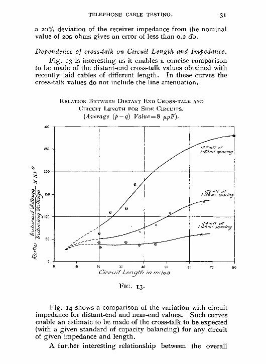
Dependence of cross-talk on Circuit Length and Impedance. Fig. 13 is interesting as it enables a concise comparison
to be made of the distant-end cross-talk values obtained with recently laid cables of different length. In these curves the cross-talk values do not include the line attenuation.
RELATION BETWEEN DISTANT END CROSS-TALK AND
CIRCUIT LENGTH FOR SIDE CIRCUITS.
(Average (p — q) Value= 8 NuF).
Fig. 14 shows a comparison of the variation with circuit impedance for distant-end and near-end values. Such curves enable an estimate to be made of the cross-talk to be expected (with a given standard of capacity balancing) for any circuit of given impedance and length.
A further interesting relationship between the overall
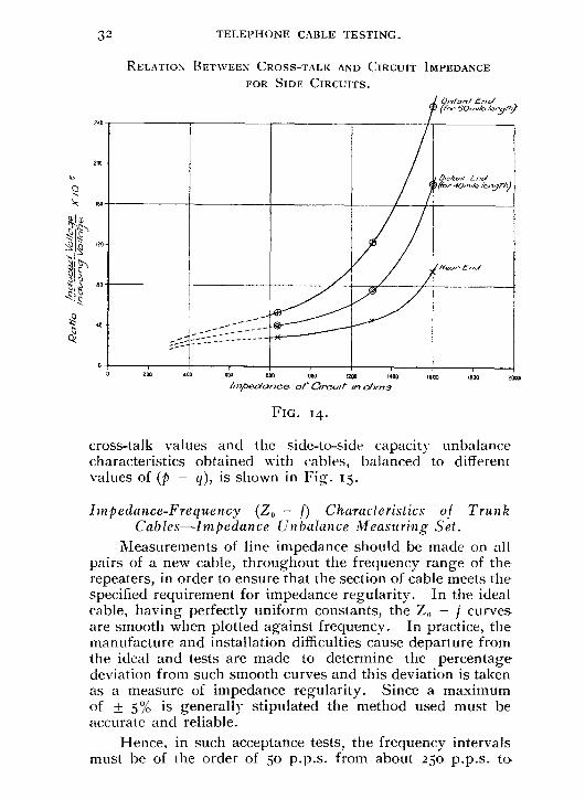
32 TELEPHONE CABLE TESTING.
RELATION BETWEEN CROSS-TALK AND CIRCUIT IMPEDANCE
FOR SIDE CIRCUITS.
(Sr•60E a
yth)
oa -
2!):6,40n.rde D,S76117i End
le,-,51-17)
60
eo
Neo, End
rf,)
200
400
600 BOO 1000 000 1400
1600
1800
2000
Impedance of Growl" rn ohms
FIG. 14.
cross-talk values and the side-to-side capacity unbalance characteristics obtained with cables, balanced to different values of (p - q), is shown in Fig. 15.
Impedance-Frequency (Z„ — f) Characteristics of Trunk Cables—Impedance Unbalance Measuring Set.
Measurements of line impedance should be made on all pairs of a new cable, throughout the frequency range of the repeaters, in order to ensure that the section of cable meets the specified requirement for impedance regularity. In the ideal cable, having perfectly uniform constants, the Z, — f curves are smooth when plotted against frequency. In practice, the manufacture and installation difficulties cause departure from the ideal and tests are made to determine the percentage deviation from such smooth curves and this deviation is taken as a measure of impedance regularity. Since a maximum of ± 5% is generally stipulated the method used must be accurate and reliable.
Hence, in such acceptance tests, the frequency intervals must be of the order of 5o p.p.s. from about 25o p.p.s. to
O
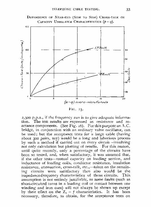
TELEPHONE CABLE TESTING. 33
DEPENDENCY OF NEAR-END (SIDE TO SIDE) CROSS-TALK ON CAPACITY UNBALANCE CHARACTERISTICS (p - q).
/ 77m if. 80
- 82
44rn
- 100
5 10 15
20
(P-17) nner-o -micro fa rwra's
FIG. I5.
2,500 p.p.s., if the frequency run is to give adequate informa-tion. The test results are expressed as resistance and re-actance components. (See Fig. 16). For this purpose an A.C. bridge, in conjunction with an ordinary valve oscillator, can be used ; but the acceptance tests for a large cable (having about 300 pairs, say) would be a long and laborious process by such a method if carried out on every circuit—involving not only calculation but plotting of results. For this reason, until quite recently, only a percentage of the circuits have been so tested, and, when satisfactory, it was assumed that, if the other tests—mutual capacity on loading section, and inductance of loading coils, conductor resistance, insulation resistance, attenuation, cross-talk, etc.,—taken on the remain-ing circuits were satisfactory then also would be the impedance-frequency characteristics of those circuits. This assumption is not entirely justifiable, as some faults (such as short-circuited turns in a loading coil or contact between one winding and iron core) will not always be shown up except by their effect on the Zo — f characteristics. It has been necessary, therefore, to obtain, for the acceptance tests on
150
100
50
10 10

TELEPHONE CABLE TESTING.
400 GOO 800 1000 moo Iwo moo 1600 2000
2200
2400
FREQUENCY (CYCLES PER SECOND).
FIG. 16.

TELEPHONE CABLE TESTING. 35
repeater cable sections, an accurate and rapid measurement of the impedance regularity, and the instrument used for recently laid cables is briefly described below and some examples of its use are given. The set—called an Impedance Unbalance Measuring Set—which was developed by the International Standard Electric Corporation, can also be used for main-tenance testing in order to ascertain whether any change has taken place in the impedance of the line.
Impedance Unbalance Measuring Set.(9 )
Principle of the Set. (a) A simulating network is designed to have an
impedance, over the working range of frequencies, equal to that of a line with uniformly distributed constants having the mean constants of the normal line in conjunction with which the net-work is to be used. If the network is correctly designed its impedance (ZN) — frequency charac-teristics will give smooth curves passing as mean curves through the actual line impedance (ZL) curves. See dotted curves in Fig. 16.
(b) As in the case of two-wire repe.4tered circuits, this network and the line under test are connected to a differential transformer (see Fig. 17) or its
Z
D
FIG. 17.
36 TELEPHONE CABLE TESTING.
equivalent. If ZL = ZN, any outgoing energy from AB produces no p.d. across CD. If ZL * ZN, energy from AB produces a potential difference across CD and the magnitude of this p.d. is utilised as a measure of the impedance deviation between the line concerned and its associated network.
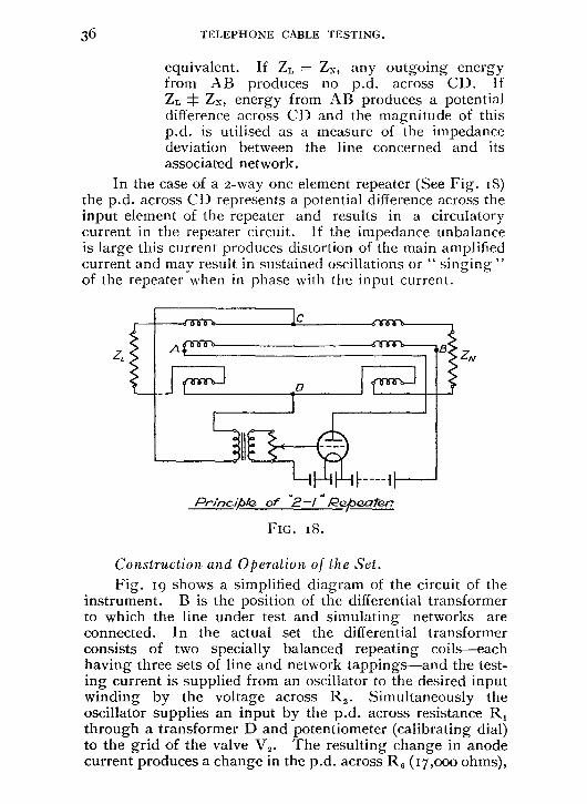
In the case of a 2-way one element repeater (See Fig. i8) the p.d. across CD represents a potential difference across the input element of the repeater and results in a circulatory current in the repeater circuit. If the impedance unbalance is large this current produces distortion of the main amplified current and may result in sustained oscillations or " singing " of the repeater when in phase with the input current.
0 0 006
if o foaat.--
r ii
Principa of "2-1 " Repeatar?
FIG. 18.
Construction and Operation of the Set.
Fig. 19 shows a simplified diagram of the circuit of the instrument. B is the position of the differential transformer to which the line under test and simulating networks are connected. In the actual set the differential transformer consists of two specially balanced repeating coils—each having three sets of line and network tappings—and the test-ing current is supplied from an oscillator to the desired input winding by the voltage across R2. Simultaneously the oscillator supplies an input by the p.d. across resistance R, through a transformer D and potentiometer (calibrating dial) to the grid of the valve V2. The resulting change in anode current produces a change in the p.d. across R6 (17,000 ohms),

37 TELEPHONE CABLE TESTING.
0 24 V,-
CALIBRATING POSITION
LINE
T = 20 DECIBELS
0 130 V +
R6
0 130 v -
SHUNT
BIAS DIAL
DENOTES MEASURING POSITION. I 0 24 v. +
FIG. 19.
CIRCUIT DIAGRAM OF APPARATUS FOR THE MEASUREMENT OF
IMPEDANCE UNBALANCE.
RIB • •
:al
LII NETWORK R4
% \
CALIBRATING DIAL D
R 3
i'vot? MEASURING
DIAL'
L. 20 DECIBELS
OSCILLATOR

38
TELEPHONE CABLE TESTING.
which is a similar resistance to R,, the p.d. across which is governed by the anode current of V,. The grid of V3 is coupled through the amplifier V,, measuring dial, the 1' net-work and transformer C to the bridge terminals of the differential transformer, and thus the p.d. across R, depends on the amount of unbalance between the line and simulating network at B. The shunted galvanometer G (of reflecting type) is connected between R5 and R. so that the galvano-meter spot is at zero when the anode currents of V2 and V, are equal.
To use the instrument it is first necessary to throw the calibrating key so that the connections are as shown dotted in Fig. 19, and adjust the calibrating dial until there is no deflection. When this condition is produced the total loss occurring between R2 and the grid of V, will be equal to the loss in the calibrating circuit between R1 and the grid of V2, i.e., 4o dbs. plus transformer losses. The loss between R2
and the grid of V, includes zo db. due to the T network, 2o db. due to the L network, (the measuring dial being cut out of the circuit) plus the losses in the transformer windings. The latter are assumed to be constant with frequency and to be the same in both positions of the calibrating and measur-ing key.
Provided the anode currents of the valves V2 and V, are equal for equal grid potentials, then, when the calibrating key is thrown to " Measure " and the measuring dial is adjusted to bring the galvo spot back to zero deflection, the dial can be calibrated to read a maximum loss in decibels up to zo (which is the value of the calibrating L-network the measuring dial replaces). The reading of the dial is actually made equal to the loss (in db.) in the external path due to impedance unbalance between line and network, but is not necessarily the same as would be obtained by ordinary sing-ing point tests. The measuring dial is continuously variable, but its scale is not an even one.
To provide for the valves V2 and V, being slightly different there is a bias dial arranged so that by its operation, with no A.C. input, the grid bias is adjusted so as to obtain zero reading on the galvanometer. Subsequent measure-ments may then be made with the requisite accuracy.
Having obtained a reading " d " on the measuring dial, the corresponding percentage unbalance between the line impedance and network impedance can, if required, be

36
34
32
30
28
I 0
O
26,
24
22
20
Ise
0
18
18 14
12
10
8
6
4
2
40°
50° 60.
75
(1,
(I)
TELEPHONE CABLE TESTING. 39
obtained from curves showing the relationship between " d " and the ratio ZL/ZN. See Fig. .20. An accuracy of 0.5 decibel can be obtained with this instrument, i.e., in effect, the impedance can be measured with an accuracy of o.3%.
SINGING POINT (db)v RATIO OF 1N1PED ANCES FOR CERTAIN ANGULAR DIFFERENCES.
0 01 02 0 3 04 0-5 06 07 08 08, 10 1
/mpea'ance
FIG. 20.
Use of the Set for Acceptance Testing Purposes.
An oscillator giving an output of about 12 milliamps, and essentially free from harmonics,. is required for the operation of the set. If, in addition, the oscillator gives a constant current throughout the frequency range required then any Zo — f characteristic can be rapidly examined by merely observing the behaviour of the galvanometer spot
12 13

TELEPHONE CABLE TESTING.
whilst the oscillator is continuously adjusted through the entire frequency range concerned.
A heterodyne oscillator,(") which enables the frequency of testing to be varied throughout the entire range by the rotation of the dial of a small air condenser, secures a con-siderable speeding up of the rate of testing. An oscillator (designed and constructed in the Research Section) which fulfils all the foregoing conditions has been successfully employed and circuits completely tested for impedance regularity (giving for each circuit the maximum difference of impedance from the simulating network) at the rate of from zo to 3o per hour as against the rate of from 2 to 3 per hour by means of an ordinary A.C. impedance bridge.
Fig. 21 is an external view of the unbalance set.
EXTERNAL VIEW CIF Z, UNBALANCE SET.
FIG. 21.

TELEPHONE CABLE TESTING. 41
Measurement of Attenuation and Phase Constant Characteristics.
It is evident that one method of measuring attenuation is by the direct method of measuring the sent and received currents, but the accuracy is limited by that of the measuring instruments. For this reason direct reading sets are not generally used for acceptance testing. Two other methods are in use, viz. :—
(i) The Open and Closed Impedance Method.(") (ii) The Mayer Method.(")
The first method, as the title implies, necessitates two measurements of impedance at the frequency of test—one with the distant end open (Z,) and one with it closed (Zc).
Then if 1 is the cable length and writing Ze --= N/M p, the
Zf
attenuation constant (/3) is calculated from the formula :-
2 V IVI TatIll 2/31 =
±—m- cos p
and the phase constant (a) is calculated from :-
2 M Tan 2a/ — 1
— M sin p
These involve lengthy calculations, particularly in the case of very long circuits, although somewhat simpler formulae can be employed in such cases.(")
This method, though fundamental and accurate, is a very slow one.
The Mayer Method has been used as a rapid method for acceptance testing purposes with satisfactory results. Fig. 22 shows the circuit arrangement. Adjustments of r and the frequency of supply are made simultaneously until the tele-phone receiver is silent. When silence is so obtained the total attenuation at the frequency of supply is given by :-
2(r + z000)
if the circuit tinder test is uniform and electrically long. In the case of coil-loaded cables or circuits which are not electrically long (81 < 2) it is necessary to terminate CD with the characteristic impedance and use the formula :—
/3l= Z loge r (I)

TELEPHONE CABLE TESTING. 42
FIG. 22.
r + 2000 131 -= 2 loge
DA • Dori>.Jr Aai11sr.a4..6 essisrA"rce
C - BALANCED • SCREENCO -rliAniotrOOMIr-R
P FOCCO REISISTAreCC NON liCACriVe 1000 0~6 EACH
ADJUBTAZU-E 0168,SVANCL.
P - sp, Piap.c.Or or BALANCED SCARCZNCO rii.awsroo.ra.
S • szcoNew, Cr $
(2)
r + 2000
The expression represents in this case the r
ratio of voltage at the receiving end to that at the sending end. The ratio is exactly twice this value when CD is not terminated.
[In the general case of a short length of line, untermin-ated, the equation becomes :—
r + 2000
)3 1 = cosh-'
The impressed voltage wave, travelling out along the loop from AB, changes both in magnitude and phase•during propagation to the receiving enc. The adjustment of r equalises the magnitude9f the received voltage to the tapped off voltage, whilst adjustment of frequency is made until the phase of the received voltage is the same as that of the tapped off voltage, when no current flows in the transformer. By reversing the connections at A and B the frequency will require adjustment in order to swing the phase of the received voltage at CD through r radians and so obtain silence again.
At each frequency ,(f) for which silence can be obtained
in the telephone, the total phase angle (24) of the received voltage with respect to the sent voltage must be a multiple of r, i.e.,
fir Cement AnbrwaSorl
IS SO
10 ribodenythCbrssbn.
faxkonaqm-A*
A
03O
TELEPHONE CABLE TESTING. 43
2a1 = TOT (3)
where n is any integer. The value of n may be determined (I) by calculating the approximate value of a from the formula 274V CL if the circuit is loaded and 4/ rfCR if it is an unloaded circuit ; (2) by obtaining the total number of silent points existing, for straight and reversed connections of AB, from zero frequency up to the frequency f.
The advantages of the method are : —
(I) Simplicity of apparatus. (2) It can be used for lines too long for the satisfactory
application of the open and closed impedance method.
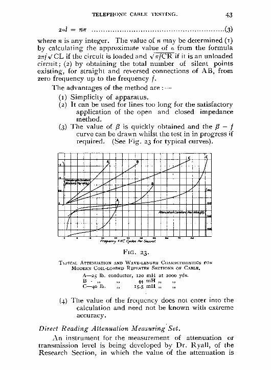
(3) The value of f3 is quickly obtained and the fl — f curve can be drawn whilst the test in in progress if required. (See Fig. 23 for typical curves).
Ftwurrloy /O. Cycle. Aro-Second
FIG. 23.
TIPICAL ATTENUATION AND WAVE-LENGTH CHARACTERISTICS FOR MODERN COIL-LOADED REPEATER SECTIONS OF CABLE.
A-25 lb. conductor, 120 mH at z000 yds. B— „ 7, 44 mH C —4o lb. „ 15.5 mH „ „
(4) The value of the frequency does not enter into the calculation and need not be known with extreme accuracy.
Direct Reading Attenuation Measuring Set. An instrument for the measurement of attenuation or
transmission level is being developed by Dr. Ryall, of the Research Section, in which the value of the attenuation is

Oscillator Unit (2 Valves)
Earthed Screen Ractlfier
3 LowPass Filter
- ,soo laps
FIG. 24.
Screened Leads
Earthed Screen
Output to Detector Grew
Amplifier
Ileterodyniny Osci Italor
Heterodyne Ifni? Volue.s
Screened Leads
44 TELEPHONE CABLE TESTING.
given directly by the deflection of the galvanometer. The range covered is from levels of + 20 db. to — 4o db. for fre-quencies from 35 p.p.s. to 30,000 p.p.s. The galvanometer deflection is equivalent to 5 mm. per decibel. The instrument can also be used for impedance unbalance measurements.
High Frequency Tests. The introduction of specially loaded circuits having a
cut-off frequency of about io,000 p.p.s. for the transmission of music has recently called for attenuation and cross-talk measurements up to frequencies approaching this value. The method mainly employed is similar to that used for carrier frequency tests.(") The scheme is illustrated in Fig. 24.
Briefly, a second high-frequency oscillator, which is tuned to have a frequency about I,000 p.p.s. higher than that of the main oscillator, is included in the detector circuit and the audible beat note, (i,000 p.p.s.), after passing through a low pass filter, is used in balancing the bridge : otherwise the pro-cedure is the same as that indicated in the case of audio-frequency tests.
Visual methods can also be applied.

TELEPHONE CABLE TESTING. 45
Cross-talk and A.C. Bridge Measurements by Visual Methods.
Until recently the most accurate results have been secured in A.C. bridge methods of testing when it has been possible to use " null " methods, with a telephone receiver as the detecting instrument. This is due to the extreme sensitivity of the human ear to small sounds. Outside the audio range of about 200 to 3,000 p.p.s. the sensitivity falls off very rapidly on account of the particular acoustic properties of both the receiver and the ear. Accurate testing at the lower fre-quencies can be done with a vibration galvanometer, and at the higher frequencies an audible testing note can be pro-duced in the detector circuit by heterodyning. Direct methods of measurement, by means of A.C. voltmeters, etc., are, of course, available at all frequencies, but these methods are not suitable where a high degree of sensitivity is required.
When testing by aural means, silence in the testing room is very desirable, since any extraneous sounds are detrimental to the accuracy of observation. Reasonable freedom from noise can usually be secured in the laboratory, but when making tests on installed cables, it is the exception rather than the rule to find the conditions favourable for aural testing. Accurate testing in noisy situations is a matter of much difficulty and, of course, the rate of progress is much reduced, while considerable 'strain is imposed on the operator. The superiority of visual over aural methods in such circumstances is therefore apparent, providing, of course, the sensitivity of the visual method is adequate.
The difficulty in the past has been mainly in the provision of the desired sensitivity. The requirements to be fulfilled are roughly that an input alternating voltage of about 1 x Io volts should give a discernible deflection of the visual record-instrument. An amplifier has been constructed which, when coupled through a copper-oxide rectifier to a Tinsley portable reflecting galvanometer, will give, for an A.C. input voltage of 0.1 x Io-6 volts, a D.C. output current of 2 µA. which produces a scale deflection of 20 mm on the galvanometer.
The amplifier is resistance-capacity coupled (see Fig. 25) and will operate efficiently from so to 10,000 p.p.s. with an amplification of too db. over the greater part of the range. Special precautions have to be taken in the mounting of the first two valves to prevent microphonic troubles and the valves are enclosed in metal foil cylinders packed with cotton wool.
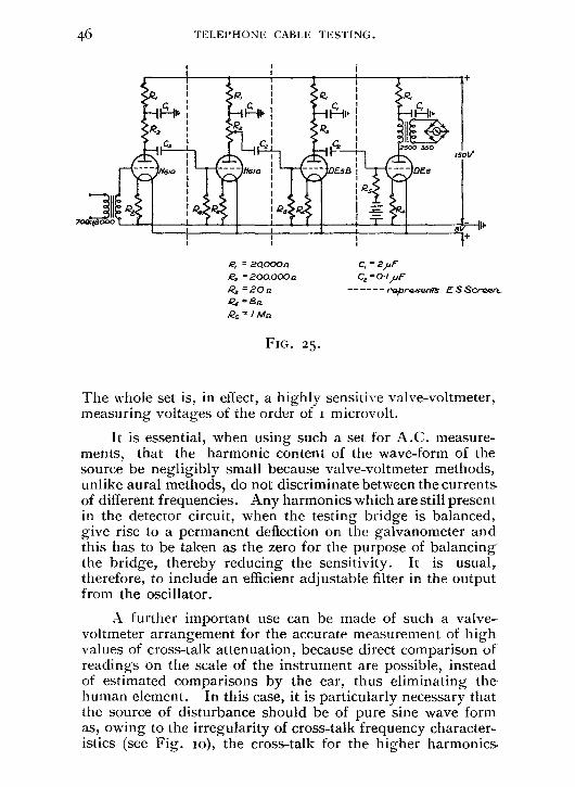
Ra
TELEPHONE CABLE TESTING.
12_,1
R,
R,
-r- 1'1610 DE58
46
R, = 20000n = 200000a
• = 20a Q4 =8n Rs = I Ain
C, - 2pF ;.0.1/uF roprasents ES Sewer,.
FIG. 25.
The whole set is, in effect, a highly sensitive valve-voltmeter, measuring voltages of the order of I microvolt.
It is essential, when using such a set for A.C. measure-ments, that the harmonic content of the wave-form of the source be negligibly small because valve-voltmeter methods, unlike aural methods, do not discriminate between the currents. of different frequencies. Any harmonics which are still present in the detector circuit, when the testing bridge is balanced, give rise to a permanent deflection on the galvanometer and this has to be taken as the zero for the purpose of balancing the bridge, thereby reducing the sensitivity. It is usual, therefore, to include an efficient adjustable filter in the output from the oscillator.
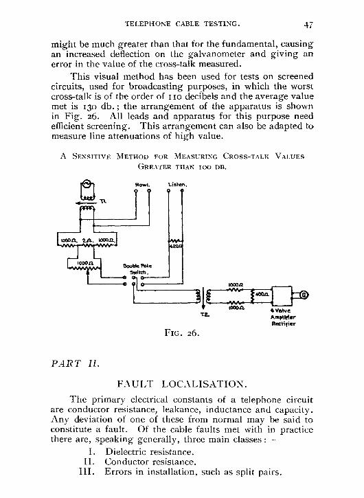
A further important use can be made of such a valve-voltmeter arrangement for the accurate measurement of high values of cross-talk attenuation, because direct comparison of readings on the scale of the instrument are possible, instead of estimated comparisons by the ear, thus eliminating the-human element. In this case, it is particularly necessary that the source of disturbance should be of pure sine wave form as, owing to the irregularity of cross-talk frequency character-istics (see Fig. to), the cross-talk for the higher harmonics.
4 Valve Amplifier Rectifier
FIG. 26.
Mows.
TELEPHONE CABLE TESTING. 47
might be much greater than that for the fundamental, causing an increased deflection on the galvanometer and giving an error in the value of the cross-talk measured.
This visual method has been used for tests on screened circuits, used for broadcasting purposes, in which the worst cross-talk is of the order of I io decibels and the average value met is 130 db. ; the arrangement of the apparatus is shown in Fig. 26. All leads and apparatus for this purpose need efficient screening. This arrangement can also be adapted to measure line attenuations of high value.
A SENSITIVE METHOD FOR MEASURING CROSS-TALK VALUES GREATER THAN TOO DB.
PART II.
FAULT LOCALISATION.
The primary electrical constants of a telephone circuit are conductor resistance, leakance, inductance and capacity. Any deviation of one of these from normal may be said to constitute a fault. Of the cable faults met with in practice there are, speaking generally, three main classes :—
I. Dielectric resistance. II. Conductor resistance.
III. Errors in installation, such as split pairs.

48
TELEPHONE CABLE TESTING.
When making the electrical tests outlined in Part I. of this paper, if a cable fault is detected, the action of the indicator—telephone receiver or galvanometer needle—used in the test set, will often give a clue to the nature of the fault, e.g., when measuring side-to-side capacity unbalance characteristics a split pair in the quad will cause a deafening noise in the telephone receiver and the phantom to side read-ings will be exceptionally high, whilst, when using a direct reading bridge, a short-circuit in a pair results in no sound in the telephone receiver when measuring side-to-side character-istics or when balancing phantom to the faulty pair. Having ascertained the nature of the fault the best localisation method available should be applied, and the result checked by another method or a number of methods—to ensure a reliable localisa-tion. The choice of a basic test (simple Varley loop, Murray loop, etc.) for the best method of localisation is sometimes easily made, as in the case of a simple earth fault with other good wires readily available ; but in other cases, such as a complete breakdown in paper-core sea cables, the nature of the fault does not permit accurate localisation by the applica-tion of a simple D.C. test. In such cases, A.C. tests at audio frequencies may often be used to obtain more reliable results, since these methods are essentially independent both of temperature and of the variation of fault resistance during the period of testing.(16) Moreover, telegraphic induction does not affect the tests.
Methods of localisation using A.C. at audio-frequencies can also be applied to conductor resistance faults and give results which are generally comparable with those obtained with the ordinary Wheatstone bridge. In the case of long cables experience shows that the A.C. tests are to be preferred.
The following Schedule I. gives an analysis of the principal forms in which the three classes of fault, already mentioned, are liable to be met, whilst Schedule II. gives the corresponding circuit arrangements and requisite formula✓. Many of the D.C. tests are well known(5) and are not described in detail. Methods employing A.C. are not so well known and are discussed in more detail at the end of Schedule II.

Class. I. Dielectric
Type. Full Earth.
Contact with or without earths.
a. h.
{d". e. f•
Intipient earth.
Complete Breakdown. m.
Complete disconnection.
II. Conductor
1 n. a. b.
d C.
TELEPHONE CABLE TESTING.
SCHEDULE I.
PRINCIPAL TYPES OF FAULT AND APPROPRIATE LOCALISATION TESTS. (D.C. UNLESS OTHERWISE STATED).
Test. Simple Varley. Simple Murray. Simple Varley. Simple Murray. Overlap. Open and closed resistance. Sending-end impedance-frequency (A.C.) Double-ended Varley. Single-ended Varley with appropriate
correction factor. Double-ended Murray for short cable
lengths. Single-ended Murray with appropriate
correction factor. Loop (if possible) or overlap (open and
closed). Impedance-frequency (A.C.) Varley loop, if another route mailable. Slide Wire or Ballistic. Method of Mixtures. Impedance-frequency (A.C.) Slide Wire (A.C.) for short unloaded
lengths. e. f.
Reid, ordinary. A. C. Reid for short unloaded lengths. Stevens' (A.C.) If
High Resistance h. Ritter (A.C.) in one i. Impedance (A.C.) Conductor of Impedance-Unbalance (A. C.) a pair. h. Zero-Reactance (Useful for obscure faults)
A.C. 1. Crosstalk frequency (A.C.)
Partial or ) Intermittent f One or more of the tests e to 1. Disconnection.
III. a. Mutual Capacity (A.C. or D.C.) Instal- Split b. Impedance-frequency (A.C.) lation Pairs. -( c.
d. Zero-Reactance (A.C.)
errors. Crosstalk-frequency (A.C.) Inductance tests if cable is not too long.
Split Loading f i.
. Impedance-frequency (A.C.) Coils. g.
h. Zero-Reactance (A.C.) Crosstalk frequency (A.C.)
Loading Coil faults such as Short Circuited turns in loading coil, contact between con-ductor and iron core, etc.
i. j. k. 1.
Impedance-Unbalance (A. C.) Impedance-frequency (A.C.) Zero-Reactance (A.C.) Crosstalk-frequency (A.C.)

SCHEDULE II.
Refer enc Number. Sched 1.
FAULT. TEST.
1.a Dielectric Full Earth
Simple Valley Loop
DIAGRAM OF' CIRCUIT ARRANGEMENT.
Good ,re
E
F It
FORMULAS REQUIRED.
If P = 0
a b — R x = - ohms 2
i.e., x = Loop—Varley Reading
2
Ifa =b=
x = / — R ohms
2
NOTES.
This basic test is unsuitable if the fault resistance, F, is so high as to be comparable with the normal insulation of the circuit. In this case either a double ended test must be taken or a correction factor applied. See below, I.h and Li.
lob Fuil Earth Nlut ray Loop Test
x = (a+b) ohms 13 +0
i.e., x = Slide Wire Rdg. x Good Loop
If a = b = I
x = 0 P+Q
• 21 ohms or
miles depending on limensions of 1
Slide Wire Reading is between S and T2 and is denoted by Q. When F is compal-able with the normal insulation, a double ended test will give the best results or a correction factor may be employed for single ended readings. Better than Varley when testing on short cable lengths.
Lc Contacts Varley Loop Test
If P=0
21 — R x ohms
i.e., X Loop—Varley Rdg.
2
Best test for long circuit. Having localised within small limits, say to a L.C.S., a Murray loop test on the shorter length will give an accurate localisation if re-quired.
-x

I.d Contacts Murray Loop Test
9 x =
14-6. 21, ohms or
miles depending on dimensions of I
Best test for short lengths. 1 '
P o
I.e Contacts Overlap Test (a) (Free) A
P.0 e B . 21-HRa — Rb) (a) Tests taken with Wheat-
stone Bridge from each end A and B with distant end free. Not often used. A better test is the closed one : —
—.._ +RI) (a) x —
4 ohms
• x ---,—......y _.,.
I.e Contacts Overlap 'lest (/3) (Closed)
...-
A x - -e-. .5 Ra(21 — Rb) (0) Tests taken with Wheat-
stone Bridge from each end of same pair with distant end closed. Battery and variable resistance arranged at each end to give same current through fault and in same direction. Fault resistance must be low compared with loop resistance.
(i3) x = 2(Ra —Rb)
I 1 _ Rb(21 —_Ra) I 120--.- IF Ra(2I — Rb) I oh ms
-. 121, A B
I.f Contacts Open & Closed Resistance
Test (Blavier Test)
lzc
x = ;1{ Rc— Test taken with Wheatstone Bridge. Not a very reliable test. Useful as a check in cases where " F " remains fairly constant during period of test.
Rf = Bridge reading with distant end open.
Re = Bridge reading with distant end closed.
4/(12f —Re) (21— Re) }ohms R, ..---X ---...- R
t. IF )

I.g Contacts Sending End Impedance Frequency A.C. Test. 1-----x —•-1
x. = K ÷ f - f = mean frequency interval between successive maximum points of the bridge resistance-frequency curve. K = constant found by experiment with a fault at a known distance or
1 F zo .e.,
1
Tarrnmorton given approximately by --
2 Vet, in the case of a loaded cable. Useful especially on a long circuit when F is varying and for a complete breakdown when no other good wire is available. See page 56.
E
1.6
•
Incipient Low. LIZ.
Double Ended Vat ley Test
Rb If Double Ended Test is not possible, apply one of the tests given in " Li."
Kt and K2 are used for Loop- ing when required Batteries at each end A and B equal voltage with same pole to middle point of ratio arms P. Tests can be made with bat- tery to earth instead of as shown to other wire of Faulty pair.
x — Ru + Rb I
.._lialinaMin II 0
P soov 1- I
a -r,,,,,,,„„,
Poo
I FE t" T V'ed p . r
Good Wro
B 2Io P
F 500V I1
i a 20000a Fo,u,ry „,,,, 20000rk
I.i I,ow I.R.
Single Ended Varley Test
with correc- Lion factor
Case I. If a =
R x = 1—
2 -(14-
i.e., if N= 150 Mfg F= 50 MD
x ••= I — 65
x = [(half the loop)—(Varley multiplied by
1(i + 2NF ))]
h =
2F
N )
and
K or
good reading
factor
Case I. Fault just developing
" F " comparable with the
normal insulation resistance " N " and one wire, at least normal. Difficulty arises in accurately determining " F" and in possible variation of
" F " during the period of Testing.
N = Insulation resistance of good wire.
F = Insulation resistance of Faulty wire.
Good Wire
hex b y re
P R
.---11—.- E Case I
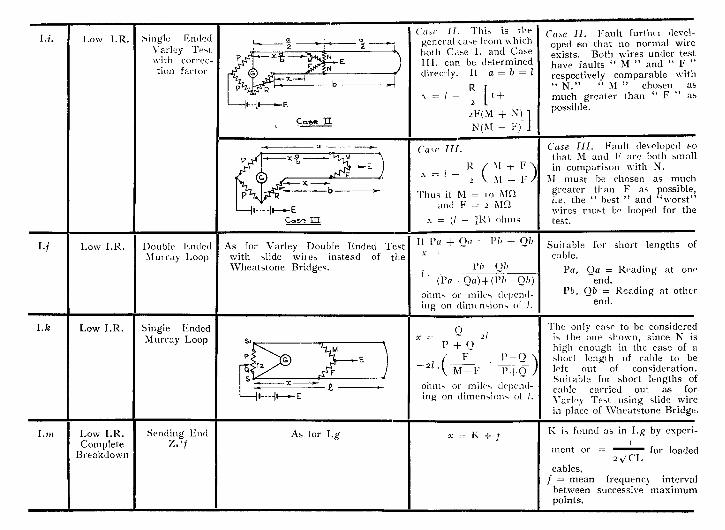
Li. Low I.R. Single Ended Varley Test with correc- tion factor
L...„____ 9- ' . -.4 ( lase II. This general case trom both Case I. M. can be determined
directly. II
R x = 1 -
2
2F(M N(M
is the w hich
and Case
a = b = I
[1+
± N) 1
- E) ..I
Case II. Fault Furth( r (level- oped so that no normal wire exists. Both wires under test have faults " M " and " F " respectively comparable with " N." " M " chosen as. much greater than " F " as possible.
. - x-E —7^11111111.11
F 0 '
‘ .-...-I _ P r R
a --11----.-E
Case II
a Case /I/.
R ( 11 --t- F ) x = I
, \ M -- I, /
Thus it M = to MD and F = 2 MD
x = (I - 7K) (dims - -11-e-E wires
Case HI. Fault de\ eloped ,sc that M and F are both small in comparison with N.
M must be chosen as much greater than F as possible, i.e. the " best " and 'worst"
must be looped for the test.
-,-- --,-- b
I-
R
C..5^ la
I.j Low I.R. Double Ended Mur ray Loop
As for Varley Double Ended Test with slide wiles instead of the Wheatstone Bridges.
It Pa + Oa = Pb + Qb
x = PI, -Ob
I
Suitable for short lengths of cable.
Pa, Oa = Reading at on, end.
Ph, (fib = Reading at other end.
(Fa - 0a)--F (Pb - (fib)
ohms or miles depend- ing on dimensions of I.
I. k Low I.R. Singie Ended Murray Loop , C) x = ,/
P + 0 i F 1' - 0
The only case to be considerec is the one shown, since N is high enough in the case of short length of cable to 13•E left out of consideration
Suitable for short lengths a cable carried out as fns Varlet Test using slide win in place of Wheatstone Bridge
P
Q -21 . M- F P---t-- 0- )
ohms or miles depend- ing on dimensions of 1.
s x _ 1--- II e-E
Luz Low I.R. Complete
Breakdown
Sending End Z. f 1
As for I.g x = K ÷ j K is found as in I.g by experi•
meat or = for loade( 2 N/ CI.
cables. f = mean frequency interva between successive maximutr points.

II.a Conductor Resistance (Complete
tion)
Slide Wire Ballistic([1111
2sitolOV P. _ Ci 2/ X =-
P -I- Q i.e., x =slide wire reading x 2/
Two wires only available for test. Upon reversal a double kick is often experienced. A better test is the method by mixtures. II.b.
•
s
L Disconnec-
-.,--x —,.-1,44.411), Wire P
72 0 Q
J Good Wire
11.a Disconnec- tion
Slide Wire Ballistic
0 A = . 21
P + Q Four Wires available for test. The wires connected to G will be a pair, or one wire of each pair bunched, depending on type of cable.
E--`—'- 251.,,loy s, 4-x--0- H
P c
— -1
S
II. b Disconnec- tion
"Method at Mixtures "
(2 Wire available)
....
4.1
.1 E
K I Good Wire
0 ' = P + 0 2?
Two wires only available for test. A double pole six terminal switch is required or its equivalent. Galva. Key K, is not depressed until switch has been thrown from "Charge" position to " Mix" position. The time allowed for mixing will vary with circuits under test from a fraction of a second upwards.
--1-- mix - ) Cho Fotalry Wire
Z
s, p Q s
II.b Disconnec- Lion
" Method of Mixtures "
(4 Wire available)
P Q 3 + 0
\ = 21 1
Four wires available for test. Apparatus as for foregoing See II.a. KI
T1 x---.- ....--i-x --..-
I Lc Disconnec- Sending End As for I.g x = K -:- f Suitable for long circuits. Kis found as for I.g by experi- ment with an open circuit
introduced at a known dis- tance.
I I.d Disconnec- tion
Slide Wii e [A.C.]
•---, Le •-• Si X A ---
1-' + Q
Q 21
0
Suitable for short unloaded
lengths. [cp. Lb] P Foully or
4 7 }Good Poor

II.e High Re- sistance in one con- ductor of
Reid [D.C.]
H R FouIt R
( / — Y) = .E, I
R x = 1 ( i _ F.
)
Suitable for long cable. Switch S enables loop resist- ante to be measured for checking steadiness of " F,''
the testing current should be limited to as small a value as possible.
x ---1-4—t-x--.- Faulty Row
it R
a pair. and Good Pair
rr
4 to 405
II./ High Re- sistance in one con- ductor of a pair.
Reid (A.C.)
X F R x=1(1— F
R _ x = 1,_ I
Suitable for short unloaded cable lengths. Solution as for II.e. Buzzer or oscillator sup- ply instead of battery and telephone replaces galvo. in foregoing test. See appendix.
erx---.- p
Good Pow.
11.g High Re- sistance in one con- ductor of a .pair.
Stevens (A.C.)
A x ____.__F a +b-i-F \ R X —
Suitable for short unloaded cable lengths. See page 64 and appendix.
Fouity Wire VA E 2000 -1- R 1 F I R tom .-I Looped
,000 Good Wire I B
--, Good Pow Looped
ell
11.h High Re- sistance in one con- ductor of a pair.
Ritter (A.C.)
d'—"r —.---4 x'..- _ x=7 ,\/ Ro \/ Ro = /
Rc F
Rc = Balance with ends bunched.
Ro = Balance with ends open.
F = Fault resistance.
Suitable for a short unloaded length of cable.
Rc = F.
e. 3 K, F=R`
niti ri K2 R b

56 TELEPHONE CABLE TESTING.
A.C. Methods of Fault Localisation. The impedance of a cable circuit is of the form :
Zjo =A+jB
where Z = V A' + B2
= tan' B/A
A convenient form of bridge for measuring the sending-end impedance on long lengths of cable is shown in Fig. 29(a). The resistance component of such a bridge is non-reactive and has a range from o to 11,1 1 1 ohms (in steps of o.i ohm). The condenser is a low power-factor Sullivan 3-dial 2 µF. condenser, (in steps of o.oui µF) in parallel with a o - 1,200 µµF air condenser with an accuracy of about o.t per cent. The impedance is calculated from the values of R, C and frequency.
For balance :— R
,s/ i + w2CIR2
tan-' wCR.
This solution is the same, numerically, for either position of the capacity, q being positive or negative depending on the position of C. A discontinuity, (such as a contact or a disconnection), in a transmission line will cause waves to be reflected from it. When these reflected waves reach the source they will differ in phase from the transmitted waves by an angle depending on the frequency, the distance to the discontinuity and the constants of the line. When the trans-mitted and the reflected waves are in phase at the sending end, the current will be a maximum and the impedance a minimum ; and when the two waves are in opposition the current will be a minimum and the impedance a maximum. Hence, in an impedance-frequency run, the bridge readings will show maximum and minimum values corresponding to these points.(") For the purposes of fault localisation, the bridge resistance readings can generally be used in place of the calculated impedance values.
I. Contact Fault or Complete Breakdown.
If x is the distance to the fault the formula required is :—
x = K f

TELEPHONE CABLE TESTING. 57
where f is the mean frequency interval between successive maximum points of an impedance-frequency curve. K is an empirical constant which should first be determined by intro-ducing at a known distance (1), generally the distant end of a similar circuit, a known contact resistance. From the result-ing measured impedance-frequency curve the mean interval (f') between successive maximum points is obtained and, from the equation, K = 1 x f', the required constant, for use in connection with the localisation, is obtained. (See Fig. 27).
400 BOO 1200 1600 2000 2400
Frequeny(Cycies per second)
FIG. 27.
(Note.—An approximate value of K for loaded cables can also be calculated from the formula :—
K = I (2) 21/ LC
where L and C are the inductance and capacity, respectively, per unit length of circuit.)
The impedance-frequency curve obtained with the faulty circuit is then analysed and the mean value of f computed.
Instead of using impedance-frequency curves for this purpose equally reliable results can be obtained by employing bridge-resistance readings plotted against frequency through-out.
In computing the value of f it is not necessary when obtaining the requisite impedance-frequency curve that all the test frequency intervals be very small, since they are only required to obtain the number of maximum points occurring
450
I
8 400
e0 350
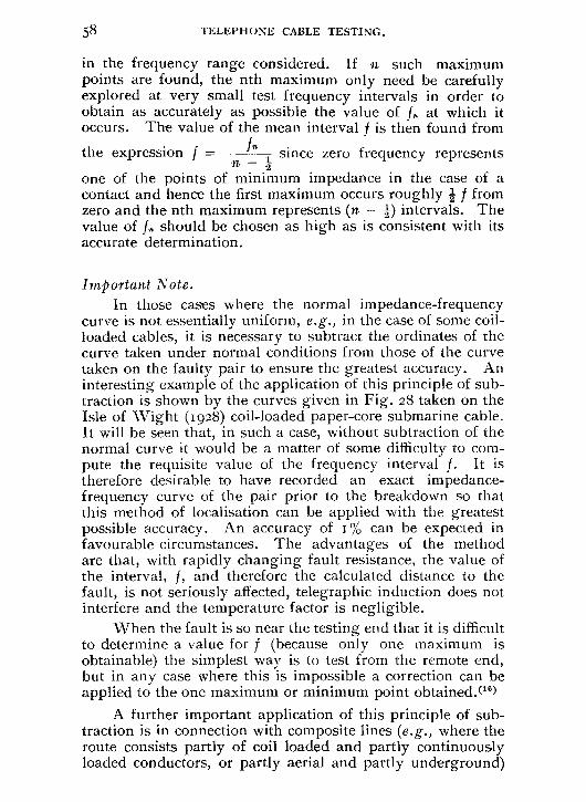
58
TELEPHONE CABLE TESTING.
in the frequency range considered. If n such maximum points are found, the nth maximum only need be carefully explored at very small test frequency intervals in order to obtain as accurately as possible the value of fn at which it occurs. The value of the mean interval f is then found from
the expression f = since zero frequency represents n 1ff
one of the points of minimum impedance in the case of a contact and hence the first maximum occurs roughly f from zero and the nth maximum represents (n — 1) intervals. The value of f. should be chosen as high as is consistent with its accurate determination.
Important Note. In those cases where the normal impedance-frequency
curve is not essentially uniform, e.g., in the case of some coil-loaded cables, it is necessary to subtract the ordinates of the curve taken under normal conditions from those of the curve taken on the faulty pair to ensure the greatest accuracy. An interesting example of the application of this principle of sub-traction is shown by the curves given in Fig. 28 taken on the Isle of Wight (1928) coil-loaded paper-core submarine cable. It will be seen that, in such a case, without subtraction of the normal curve it would be a matter of some difficulty to com-pute the requisite value of the frequency interval f. It is therefore desirable to have recorded an exact impedance-frequency curve of the pair prior to the breakdown so that this method of localisation can be applied with the greatest possible accuracy. An accuracy of 1% can be expected in favourable circumstances. The advantages of the method are that, with rapidly changing fault resistance, the value of the interval, f, and therefore the calculated distance to the fault, is not seriously affected, telegraphic induction does not interfere and the temperature factor is negligible.
When the fault is so near the testing end that it is difficult to determine a value for f (because only one maximum is obtainable) the simplest way is to test from the remote end, but in any case where this is impossible a correction can be applied to the one maximum or minimum point obtained.(")
A further important application of this principle of sub-traction is in connection with composite lines (e.g., where the route consists partly of coil loaded and partly continuously loaded conductors, or partly aerial and partly underground)

TELEPHONE CABLE TESTING. 59
400 800 1200 1600 2000 2400 Frequency 4c/es per. se.cordil
ISLE OF WIGHT (1928) COIL-LOADED SUBMARINE CABLE.
(A). Normal Impedance (Bridge Resistance readings). (B). Impedance with 20,000 ohm fault at 22.4 nauts (do.). (C). Difference Curve B—A.
FIG. 28.
for by such an application it should be possible to localise without breaking down intermediate sections. In such cases, of course, the simple equation x = K 4- f is not directly applicable, but a very similar equation may be deduced.(")
II. Continuity Fault—High Resistance in one Conductor of a Pair—Complete Disconnection.
Conductor resistance faults are frequently somewhat difficult to locate, but, by the use of several of the methods of location available, good results can be secured. The resist-ance of a continuity fault in a cable conductor is, however, generally subject to fairly rapid variation caused either by vibration of the cable (due possibly to traffic) or by the action of the testing current. Faults of a high value (e.g., above io ohms) are more subject to variation than those of lower values and this frequently nullifies the advantage gained by the high value of the fault in the case of those methods of
6o TELEPHONE CABLE TESTING.
location depending on an accurate knowledge of the fault resistance or its constancy.
In view of the inherent insensitivity of the D.C. tests and on account of the fact that most of the methods involve the determination of the value of the fault (or at least that it shall remain steady in value over a long enough period for a series of related tests to be made), A.C. methods offer great advantages in certain cases. There are two main considera-tions (a) for the case of long cables (loaded and unloaded) and (b) for the case of short unloaded lengths.
(a) Long Cables. The following A.C. methods are applic-able : —
(I) Sending End Impedance-Frequency Method. The localisation by means of an impedance-frequency
curve is carried out in a similar manner to that described for the localisation of a contact and by use of the same formula :—
x = K f
In this case, however, it is important to notice that— (i) For the determination of K a resistance (of the order
of the fault resistance) is placed in one conductor at a known distance along a similar circuit (and, if it is a disconnection which requires localisation, the value of K can be determined by analysis of impedance-frequency curve of an open-circuited similar pair).
(ii) Zero frequency represents a point of maximum impedance and hence the first maxmium occurs at a point approximately f from zero. Hence, the nth maximum represents n intervals from zero, not it - as in the case of a contact, and
expression f = nn
, where f. (the nth maximum)
is taken as high as is consistent with its accurate measurement.
(2) Cross-talk Frequency Method.(")
The localisation by means of a cross-talk-frequency run is carried out in a similar manner to that described for the foregoing test, viz., by analysis of the frequency interval

(a)
TELEPHONE CABLE TESTING. 61
between maximum points occurring in the cross-talk-frequency curve. Owing to the fact that the normal cross-talk frequency characteristics of a circuit are very irregular (see Fig. 1o) it is rarely possible to apply this method satisfactorily. For this reason the following modifications have been developed and successfully applied.
(3) Impedance Unbalance Method. The circuit connections are given in Fig. 29(b) and Fig. 29(c).
FIG. 29.
(a) Sending end Impedance Bridge. (h) Impedance unbalance Bridge, using capacity and resistance. (c) Impedance unbalance Bridge, using inductance and resistance. (d) Zero Reactance Bridge.
The circuits are terminated by their characteristic impedance. Using resistance and inductance the bridge can be connected at the testing end to produce in the telephone circuit a current equal and opposite in phase to that produced by the faulty circuit. A similar equation to that already used
62 TELEPHONE CABLE TESTING.
can be employed, viz., x = K/f and f is found by plotting against frequency the real or imaginary component of the unbalance impedance required at the bridge and obtaining the frequency interval from the equation f = f n /n. K in this
case is not simply I but is the product of side and 2 .s/ LC
phantom velocities divided by their sum, and the best way to obtain K is by experiment as before. It will be realised that this method is essentially an adaption of the previous method. It has about the same degree of accuracy when more than one maximum point is obtained in the audio frequency range. In place of the resistance and the inductance, resistance and capacity can be used, the capacity being connected in parallel_
(4) Zero Reactance Method is a modification of the one just outlined and the localisation is again given by 1 = Klf and K is found by experiment.
The necessary arrangement of apparatus is shown in Fig. 29(d). In addition to equal ratio arms, and characteristic impedance terminations, a resistance r is used which can be placed in series with the good or faulty conductor by the reversing switch S. The value of r and the frequency of supply are adjusted simultaneously until silence is obtained in the telephone. Then the frequency is increased or decreased and r readjusted until the next silent point is obtained. This operation is repeated throughout the audio range and successive frequencies so obtained indicate that the waves propagated to and from the fault have passed through 27r radians just as the successive maximum points on the impedance-frequency curve indicate a phase change of 27r radians. Such a set of silent points can be represented by the symbols, fl , f3, , f 5 • • f24+ 1 from zero.
By reversing the switch, S, a second set of silent points can be obtained having, theoretically, the same frequency interval as the first set, but displaced by 7 radians from it. This set can be represented by the symbols, f2, f4, fb • • • • f2,, from zero. The mean frequency interval, f, is then obtained
by either the equation f = 2(f,1 n) or f = 2 ( +
n — I ) depending upon the value of the frequency of the last silent point obtained throughout the frequency range employed.
The accuracy of the Zero Reactance method depends on the accuracy with which f2 or f,,,+, is determined; and the
TELEPHONE CABLE TESTING. 63
smallest value of fault resistance which can be localised is limited by the magnitude of the reflected wave compared with the resultant of the reflections received at the bridge from the existing distributed unbalances normally in the cable. Thus, in any balanced cable a conductor resistance fault of sufficient magnitude to give cross-talk of greater value than the normal can be localised by the Zero Reactance Method. Further, it possesses the following advantages over methods 1, 2 and 3 :—
(I) It is simpler and quicker. (2) It can be used for faults near the testing end when
the other two methods are not accurate due to badly shaped curves.
(3) The Zero Reactance frequencies can be determined quite definitely, whereas the maximum points in the three foregoing methods are extremely difficult to obtain definitely, especially when the value of the fault resistance is low.
When the phantom/side capacity unbalance character-istics of the faulty circuit are large, improved location may be obtained by testing to earth using a pair in a separate quad as return instead of the second pair of the faulty quad. This applies particularly to cables in which the side-to-side capacities have been balanced, but not the side-to-phantom capacities. In twin cables, tests using a second pair and also earth should be tried.
(b) Short Unloaded Lengths.
The foregoing tests are not applicable in the case of short lengths of cable, such as loading sections. High con-ductor resistance faults are usually found at cable joints, being due to defective wire joints or nicked wires. Sometimes, how-ever, faults occur in a length of cable due to flaws in the conductor. In this case an accurate location of the fault is very desirable to avoid unnecessary breaking down of the duct line or wasting of cable by replacement of too long a length. The following A.C. tests are applicable :—
(1) Ritter Test.(') See Schedule II. The location of the fault is given by the formula :-
- x = •/ (I)

64 TELEPHONE CABLE TESTING.
where the value of the balancing resistance, R, is obtained in an open circuit test ; 1 — x is the distance to the fault measured from the distant end, 1 is the length of the circuit and F the value of the fault resistance.
This test, although it has proved very useful, suffers from the disadvantage that R is usually very small, e.g., if (1— x)I1 is 0.5 then R/F is only .25. In the ordinary way rheostats are adjustable in steps of not less than o.t ohms so that if F were, say, 2 ohms and (1 — x)/l = 0.5 then R is only 0.5 ohms and the best percentage accuracy to which it can be deter-mined is generally about to%. This difficulty is minimised in the following test.
(2) A.G. Reid Test. See Schedule II. It should be pointed out that the Reid Testm can be
applied to short sections of cable using a source of A.C., such as a valve oscillator or reed hummer, instead of a battery and reversing key, and using a telephone instead of a galvano-meter as the detector. The formula is the same as for the D.C. Reid Test, viz.,
/ — x = RF • l* (2)
where the symbols have the same significance as those in equation (t) for the Ritter test. It will be seen from equation (2) that the balancing resistance, R, required is larger than that necessary in a Ritter test for a similar fault, e.g., if F is assumed to be 2 ohms and (1 — x)/l = 0.25 then R is 0.5 ohm as against 0.125 ohm required by the Ritter test. There is yet a further modification due to Mr. F. Stevens in which the difficulty of the small balancing resistance is entirely removed.
(3) Stevens's Test.
A diagram of connections is given in Schedule II. Two t,000 ohm non-reactive ratio arms are used with two 1,200 NAE air condensers, although one of the latter may be dispensed with. The condensers are required to secure a more perfect balance of the bridge, but do not enter into the solution for the location of the fault. A non-reactive resistance having a range up to too ohms in steps of o.t ohms is also required. It
* For proof of this see Appendix.

TELEPHONE CABLE TESTING. 65
the value of resistance required in the ratio of a+b+ F
and since a + b is generally not greater than WO ohms, a decided increase in the balancing resistance, R, is obtained.
The location of the fault is now given by the formula :-
1-x ( \ a +b+FR , 2000 + R F (3)
If tests are made from each end of the cable, and the value of F remains unchanged, then :-
1 -x /
R + R1( 2000 + R \ ' R1 + R (4)
(5>
where P',42" are the readings obtained at the remote end.
In the foregoing tests each wire is assumed to be of exactly the same resistance, but there may be an actual difference of up to 0.3 ohms, so that where the fault resistance is only a few ohms the normal resistance unbalance may form a source of error. Further, as in all other location tests, uniform distribution of one or more of the electrical character-istics is assumed. In this case the most Important assumption is that the capacity is uniformly distributed and balanced, and non-uniformity in this respect will lead to error. A pair in a
* For proof of this formula see Appendix.
will be observed that the balancing resistance has been con-nected in series with the ratio arms instead of in series with the line as in the Reid test. This has the effect of increasing
2000 + R
2000 +
where R' is the balance obtained at the remote end of the-cable and the fault resistance is eliminated.
If a slide wire is used instead of ratio arms and an adjust-able resistance then if P,Q are the slide wire readings
l-x a+ b+ F P- Q 1
p x F
Again, if tests are made from each end of the cable and the value of F remains unchanged, then it can be shown that :
l-x P - Q 1
(13' - V) ± (P (6)

66
TELEPHONE CABLE TESTING.
separate quad can, of course, be used for a return as in the case of the Zero-Reactance method when the cable is not balanced for phantom working. Similarly the method can be applied using an earth return. In the case of twin cables a second pair or earth return is used.
11E. Installation Errors.
Any fault which gives rise to an impedance irregularity or unbalance (such as that caused by split pairs) can be located by one of the A.C. methods already described, for long circuits. For split pairs in unloaded sections the follow-ing method has been used successfully :—
Mutual Capacity Tests for Split Pairs. Referring to Fig. 30(a), the following capacities are
measured on the faulty pairs (the wires being insulated at the distant end) :—
(I) Measure the capacities A to B and C to D. ( 2 ) „ A to C and B to D.
(3) o A to D and B to C.
MUTUAL CAPACITY TEST FOR SPLIT PAIRS.
A
(a)
Reference Capaciiy
COPCIC01 Under
(b)
FIG. 30.
TELEPHONE CABLE TESTING. 67
The mean of the two readings is taken in each case and calling these mean values K1, K, and K, respectively, then if B & C, or A & D, are the crossed wires :—
A; K, — K, (K, — K3) + (K, — K3 )
If A & C, or B & D, are the crossed wires : —
x K, K2 (K, — K2) + (K, — K2)
The equation to be used in any given case can alN\ aVS be determined by inspection of the measured values of K2 and K3. The rule is that if K2 is greater than K3 use equation (I) ; and if K3 is greater than K2 use equation (2). There is one exception to this rule, viz., when the faulty pairs are two pairs in the same quad in a Star-Quad Cable. In this case the rule is reversed because the capacity of a split pair is greater than that of a normal pair, whereas in all other cases the split pair capacity is less than the normal pair capacity.
When the fault consists of " rectified " split pairs, that is, when a second crossed joint has been made in an attempt to correct the first cross, x is the distance between the two crosses, and this information may sometimes be of help in deciding where first to open the cable. If the cable is opened between the two crosses, each can then of course be located separately.
On short lengths of cable the measurements are generally made with a Wien bridge as used for ordinary mutual capacity tests on loading sections. On long lengths of cable, a ballistic method of measurement can be employed.
On short lengths, sufficiently accurate results can be secured by using a properly graduated non-reactive slide wire having a resistance of moo ohms, or, alternatively, two resist-ances, of the order of moo ohms, in series, one of which is adjustable in steps of I ohm. The value of the fixed resistance need not he accurately known. A diagram showing the method of joining up the components is given in Fig. 3o (b), a small condenser (about 0.1 ,AF) or another cable pair being used as a reference capacity. Using this bridge the capacities K„ K2 and K3 would be successively compared with the reference capacity.
If P, /Q„ P2 /Q2, P3 /Q3 are the ratios of Ki, K2 and K3
(I)
())

68 TELEPHONE CABLE TESTING.
to the capacity of the reference pair, equations (I) and (2) can now be written
P,/Q1 P3/Q3 (P1/Q1 P3/Q3) (P2/Q2 P3/Q3)
x P,/Q, P2/Q2 (P1/01 — P2/Q2) + (P3/Q3 - P2/Q2)
respectively. It should be mentioned that a high degree of accuracy is
not, as a rule, essential in locating faults of this character as they occur at a joint. As examples a split pair gave a localisation of 62 yards by the mutual capacity method (using a Wien bridge) on a length of 32o yards, the actual distance to the faulty joint being 6o yards : again on a 716 yard length the localisation gave 450 yards while the actual distance to the faulty joint, opened as a result of this test, was 430 yards.
PART III.
SUBMARINE CABLES.
In submarine telephone cables the conductors have been, until recent years, insulated with gutta-percha and such cables are known generally as " G.P." cables. For shallow waters the paper-insulated, lead-covered type of cable has been used since 1926 and has proved to be the best type except where the sea bottom is of a very rocky nature. In such cases G.P. or balata cables are used on account of the greater mechanical strength obtainable. A sheathing of iron armouring wires is provided round the outside of each of these types of sub-marine cable to give mechanical protection and extra strength. In the case of the paper insulated cable, even with a steel spiral under the lead sheath, sufficient strength for depths greater than ioo fathoms cannot be given.
For a trans-oceanic cable, such as a Europe-America link, where depths of the order of 2500 fathoms may be met, the use of a paper insulated lead-covered cable entails special pressure-resisting shields. The use of a low leakance dielectric of the paragutta type enables the usual serving of armouring to be employed and development work indicates that no technical difficulty lies in the way of the manufacture
and
(3)
(4)

TELEPHONE CABLE lESTING. 69
of such deep-sea cables which shall be waterproof and mechanically strong under pressure.
Lead-covered Paper-core Cables. Of the principal submarine telephone cables round our
coasts, eleven of this number are of the lead-covered type and, except for the short Isle of Wight cables, are continuously loaded. The testing methods employed for these cables are similar to those already described in Parts I. and II. for paper-core underground cables. Since the manufacture and laying of a submarine cable is not of common occurrence, the pro-cesses involved are perhaps not so well known as those for underground cables and the following brief description is therefore given.
Fig. 31 shows a section of a 4-quad cable of the lead-covered type together with a 7-quad cable section, whilst the latter is shown in longitudinal section in Fig. 32 which illustrates the method of insulating the conductors.
The copper conductor comes into the factory already drawn to the required diameter and the first operation is the loading of these conductors.
In the loading machines the conductors pass through a frame carrying the bobbins of iron wire which revolve round the conductor at high speed and put on the desired number (generally one or two) of layers of the loading material. A very large amount of iron wire is used, e.g., in the case of a cable such as the Anglo-Dutch, which is more than 8o nauts long, it amounts to more than 50,000 miles of wire.
The loaded conductor is then insulated with paper in the usual manner and a further machine lays up the four con-ductors to form a quad about two miles in length. This length is cut into lengths of about 400 yards, which are wound on drums and sent for the first electrical tests. The tests consist of the measurement of the four line constants, resistance, self inductance, mutual capacity and leakance together with the capacity unbalances.
The lengths are now jointed together to form half-miles, the unbalance capacity, etc., being reduced as much as possible by crossed joints in like manner to that employed during installation and balancing of underground cable lengths. Four half-miles are then laid up round the single

FIG. 31.
ANGLO- BELC;IRN
ANGLO-FRENCH (1927).
ANGLO-D(11'CH (1924).
70 TELEPHONE CABLE TESTING.
central conductor, or central core, and the length is put into a vacuum oven and dried.
From this oven the half-mile lengths pass straight through the lead press and are then coiled on wooden drums to cool. All the electrical tests are now repeated with the addition of D.C. insulation to sheath.
These lead-covered half-mile lengths are then jointed to

TELEPHONE CABLE TESTING. 7 1
CABLE END TELESCOPED TO SHOW CONSTRUCTION.
FIG. 32.
form 21 mile lengths with test selected joints and the additional test of cross-talk is taken on the 21 mile groups. Four lengths of miles are now joined to form a to-mile
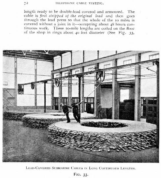
72 TELEPHONE CABLE TESTING.
length ready to be double-lead covered and armoured. The cable is first stripped of the original lead and then goes through the lead press so that the whole of the to miles is covered without a joint in it—occupying about 48 hours con-tinuous work. These to-mile lengths are coiled on the floor of the shop in rings about 40 feet diameter (See Fig. 33,
LEAD-COVERED SUBMARINE CABLES IN LONG CONTINUOUS LENGTHS.
FIG. 33.

TELEPHONE CABLE TESTING. 73
which shows three such rings) and are then completely tested for primary and secondary constants and for cross-talk. Upon completion of these tests the lengths are passed through the lead press again to receive the second lead sheath.
The armouring of each to-mile cable length commences soon after the second lead sheath has been applied and repeat electrical tests are completed. The armouring of such a length occupies about 7 days and nights of continuous work. From the armouring machine the cable lengths pass over a system of pulleys into tanks of water near the bank of the river. The armouring wires are welded so that they are mechanically continuous through the to miles. The tests as the cable lies in the tank are D.C. insulation, conductor resistance and capacity and A.C. tests for cross-talk, attenua-tion and impedance characteristics.(27)
Usually a number of these to-mile lengths are jointed in the factory to give the required overall length of cable, e.g., 7 lengths in the case of a 70-mile cable such as the Manx cable, and the complete length is passed direct to the cable ship for laying purposes. Fig. 34 shows the loading of the completed cable on to the cable ship by means of pulleys on barges placed at intervals from the bank.
FIG. 34.
Repair of a Paper-core Cable.
During repair operations of such lead-covered cables it is the practice, whenever possible, to carry out switching
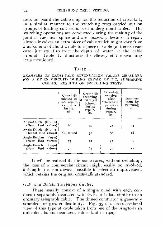
74
TELEPHONE CABLE TESTING.
tests on board the cable ship for the reduction of cross-talk, in a similar manner to the switching tests carried out on groups of loading coil sections of underground cables. The switching operations are conducted during the making of the joint at the final splice and are necessary because a repair always involves an extra piece of cable which might vary from a maximum of about a mile to a piece of cable (in the extreme case) just equal to twice the depth of water at the cable ground. Table I. illustrates the efficacy of the switching tests mentioned.
TABLE I.
EXAMPLES OF CROSS-TALK ATTENUATION VALUES MEASURED (ON A GIVEN CIRCUIT) DURING REPAIR OF P.C. SUBMARINE
CABLES. RESULTS OF SWITCHING TESTS.
Cross-talk existing be-fore repair, i.e., after
laying. db.
Cross-talk occurring
if "straight" Jointed during repair.
db.
Cross-talk existing
after "switching" operations
during repair.
db.
Improve- ment by
switching. db.
Anglo-Dutch (No. 2) (Near End values)
Anglo-Dutch (No. 3) 66 59 73 14
Distant End values)
Anglo-Belgian (193o) (Near End values)
Anglo-French (193o) (Near End values)
No record
74
77
so
64
63
68
73
75
18
9
12
It will be realised that in some cases, without switching, the loss of a commercial circuit might easily be involved, although it is not always possible to effect an improvement which retains the original cross-talk standard.
G.P. and Balata Telephone Cables.
These usually consist of a single quad with each con-ductor separately insulated with G.P. or balata similar to an ordinary telegraph cable. The tinned conductor is generally stranded for greater flexibility. Fig. 35 is a cross-sectional view of this type of cable taken from one of the Anglo-Irish unloaded, balata insulated, cables laid in 1929.

TELEPHONE CABLE TESTING. 75
No. I. (NORTH CABLE).
PORT ERIN (ISLE OF MAN). 4-CORE BALATA INSULATED TELEPHONE CABLE.
FIG. 35.
No lead is required for such a cable as the balata is waterproof in itself, but iron armouring wires are provided for mechanical protection. Fig. 36 is interesting as it gives a comparison of the weights of the materials used in the two principal types of submarine cable. It will be noticed in each case how small a fraction of the total weight the copper conductor forms and that the armouring accounts for the largest part of the weight in each cable.
Balata (a vegetable and not synthetic material) is re-placing gutta percha, which has been used in the past for submarine cable work, because it has a lower dielectric con-stant and a lower leakance than gutta percha. It also has a long life in'water, but deteriorates if exposed to air and hence shore ends of balata cables are usually insulated with gutta percha, which has better lasting qualities in air.
The manufacture of balata cables is not so complicated as that of the lead-covered type. The balata is heated to a plastic state in a container somewhat similar to a lead press and is forced through a die on to the conductor. When cold this is covered with tape. Each core is made in about two-mile lengths and cut into half miles for tests of resistance and capacity. From the results of these tests the lengths are laid
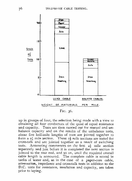
76 TELEPHONE CABLE TESTING.
iron
%Oar Copoor
sore
15
Scale
Lead
of
tons 10
20
eilato.
Joffe
Iron
Sheathing
0
LE AD CABLE BA L ATA CABLES.
WEIGHT OF MATERIALS PER MILE.
FIG. 36.
up in groups of four, the selection being made with a view to obtaining all four conductors of the quad of equal resistance and capacity. Tests are then carried out for mutual and un-balance capacity and on the results of the unbalance tests, about five half-mile lengths of core are jointed together to form a 2 mile section. These 2 mile sections are tested for cross-talk and are jointed together as a result of switching tests. Armouring commences on the first 2 mile section separately and just before it is completed the next section is jointed to the rear end, and so on, until the required overall cable length is armoured. The complete cable is stored in tanks of water and, as in the case of a paper-core cable, attenuation, impedance and cross-talk tests in addition to the D.C. tests for resistance, insulation and capacity, are taken prior to laying.
5 Iron
Sheartnivi

TELEPHONE CABLE TESTING. II
Fault Localisation.
The tests outlined in Part II. can be applied to paper-insulated submarine cables. Speaking generally, faults in such cables are due to fracture of the lead sheath by anchors, trawls, etc., and result in the paper rapidly becoming saturated with water. Consequently complete breakdown of all circuits often occurs before a Varley loop test is possible. The A.C. impedance-frequency methods have been found to give very good results and, of course, any of the D.C. methods outlined for paper-core underground cables can be applied when the corresponding requisite conditions are fulfilled.
For gutta percha or balata cables, the faults liable to occur may be classified as follow s :—
a. Dielectric fault with conductor resistance unaffected. b. Conductor resistance fault with the dielectric un-
affected. c. Combined dielectric and conductor resistance fault. d. Contact between two wires.
For faults a, b and d many of the tests applicable to paper core cables, and already described, are suitable. In type c, such as a broken end, the problem is complicated by a number of factors, viz.:—
I. The break in the cable acts as a simple cell, action being set up between the copper, iron and salt water, generating a current which flows from the conductors to the sheath and seriously affects the galvanometer deflections.
2. The testing current itself has an electrolytic action on the cable, coating the fracture with chloride of copper when a positive current is sent to line, and with hydrogen when negative current is sent. This results in a varying value of earth resistance at the fault.
3. Secondary e.m.f's, set up by the films of hydrogen and copper chloride, will appear and disappear from the circuit with these deposits and will thus be present on the removal of the testing current.
These effects are termed " polarisation " at the fault and generally result in a higher (and more varying) fault resist-ance than would accrue from a punctured dielectric alone. For the purpose of localisation, when the conductor is broken, an estimation of the true resistance of the fault, when making

78
TELEPHONE CABLE TESTING.
direct measurements of the resistance of the conductor up to and including the break, is practically a matter of guess-work and, at best, can only be approximately inferred after much experience with this type of fault. There have been a number of tests devised, based upon empirical rules, by which the effect of the fault resistance is eliminated and the conductor resistance itself up to the break is given. It is a moot point whether any one of these tests can be considered generally superior to another especially since so many factors (size of exposed surface, resistance of break, etc.) enter into the question when determining the empirical rules employed. When the resistance of the exposure is not very great the effects of earth currents and polarisation can be eliminated by Mance's Test which does not, however, give the resistance of the fault, but the resistance up to and including it. This test and methods which are designed to eliminate the fault resistance are given below and it should be pointed out that these tests, although peculiar to submarine cables at present, would assume greater significance in the event of the adoption of armoured underground cables laid direct in the earth, since some breaks would then involve polarisation effects and their attendant difficulties :—
Mance's Test.(") An ordinary -Wheatstone bridge is used, connected as
shown in Fig. 37. The procedure is as follows :—
MANCE'S TEST.
FIG. 37.
With equal ratio arms I31131f (say Ioo ohms each) and usually negative to line, obtain a balance r1, using true scale
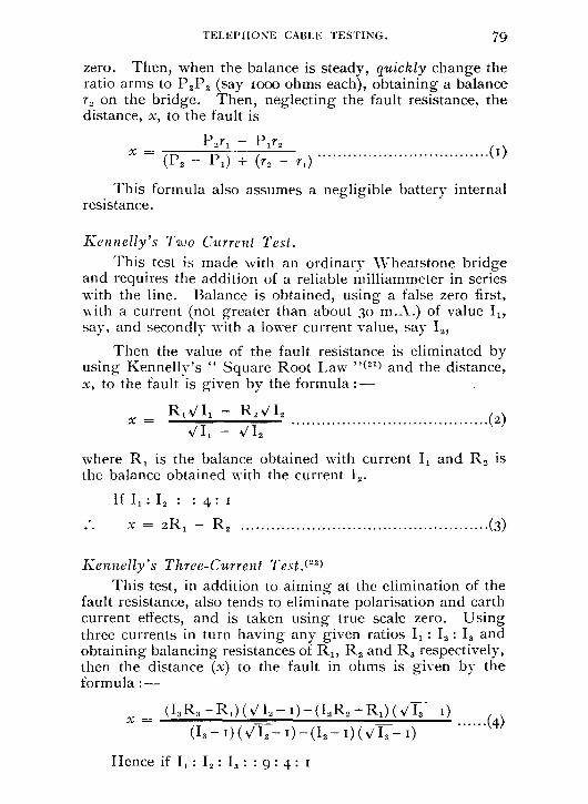
TELEPHONE CABLE TESTING. 79
zero. Then, when the balance is steady, quickly change the ratio arms to P2P2 (say moo ohms each), obtaining a balance r2 on the bridge. Then, neglecting the fault resistance, the distance, x, to the fault is
P2ri P1r2 (I)
x — (P2 — P1) + (72 — r,)
This formula also assumes a negligible battery internal resistance.
Kennelly's Two Current Test. This test is made with an ordinary Wheatstone bridge
and requires the addition of a reliable milliammeter in series with the line. Balance is obtained, using a false zero first, with a current (not greater than about 30 m.A.) of value I„ say, and secondly with a lower current value, say I2,
Then the value of the fault resistance is eliminated by using Kennelly's " Square Root Law "(21) and the distance, x, to the fault is given by the formula :—
R i VI, — R2 VI2 x — (2)
VII — VI,
where R, is the balance obtained with current I l and R2 is the balance obtained with the current 12.
If 11 : 12 : : 4 : I
.*. X = 2R1 - R2 (3)
Kennelly's Three-Current Test.(22) This test, in addition to aiming at the elimination of the
fault resistance, also tends to eliminate polarisation and earth current effects, and is taken using true scale zero. Using three currents in turn having any given ratios Ii : I2 : 13 and obtaining balancing resistances of R„ R2 and R3 respectively, then the distance (x) to the fault in ohms is given by the formula :—
X = (I3 R3 —R1 )( N/I2 — i)—(I2 R2 —R,)(VI,— I)
(I,— t)(V12— 0 -0, — WO,— I)
Hence if I, : I2 : I, : : 9 : 4 : I
(4)

.r.
SK2
Coble
So IELEPHONE CABLE TESTING.
i.e., I, : I, : I, : : I : 4 : I
9 9
.*. x = R3 — 8R2 + 9R, (5) In this " three-power " test, as it is sometimes called,
the maximum current is not limited to 3o m.A. as in the two-current test.
Modifications of the foregoing test are discussed by H. E. Cann,(") C. AV. Schaefer,(24) and J. Rymer Jones.(")
Black's Reduced Current Test.(") This is also based on an empirical rule and gives the
localisation in ohms up to the break. It has been used with success by the Pacific Cable Board in preference to the methods already mentioned. Using an ordinary Wheatstone bridge and false zero, the connections for the test are given in Fig. 38. If x is the distance to the fault in ohms, then :—
x = R — [( To
(6)
where W represents the contact resistance and can generally be taken with sufficient accuracy as equal to the conductor resistance of one naut of the conductor under test. The possibility of more accurately determining the value of AV is discussed in the references given.
BLACK'S REDUCED CURRENT TEST.
FIG. 38.

TELEPHONE CABLE TESTING. SI
R is the bridge reading obtained with any given current and should not be recorded until, upon a reduction of the current to some smaller value, say one-half, the balance remains unchanged with this value of R or a value very near it.
I is the value of the first or " unreduced " current read-ing. In an actual test to a break, a bridge reading of R = 7109 ohms was obtained (in the case of a cable with W = To ohms) when I had the value 6 milliamps, and R = 7127 ohms when I was reduced to 3 m.A. Hence x = 7083 ohms. The actual distance was 7088 ohms.
Conclusion. The rapid strides which have been made in the art of
telephone communication and the changes of technique pro-duced by the introduction of inductive loading and of thermionic valve amplifiers is reflected in the developments of cable testing methods outlined in this paper and it does not appear likely that progress in the immediate future will necessitate such radical changes in technique. The present development is rather concerned with the problems of economical design and increase of the traffic carrying capacity of the cable routes and the tests already discussed will not be changed perhaps so much in principle as in the methods of application. Any increase in the carrying capacity of a cable is accompanied by a corresponding increase in the need for rapid' and accurate means of fault localisation and for this reason A.C. methods will no doubt become of even greater value.
The writers wish to acknowledge their indebtedness to the International Standard Electric Corporation and to Messrs. Siemens Bros. for some of the illustrations shown. Grateful acknowledgment is also made for the helpful advice and assistance given by colleagues of the Cable Group in the Research Section, who have been concerned with some of the recent developments.

82 TELEPHONE CABLE TESTING.
(1)
(2)
(5)
(6)
(7)
(0 )
(0 )
(10)
(12)
(13)
REFERENCES.
I.P.O.E.E. Paper No. to4—" Cable Testing " by E. S. Ritter.
Bell System Technical Journal, Vol. VI., No. t, January, 1927.
" A Shielded Bridge for Inductive Impedance Measure-ments," by W. J. Shackleton, and Vol. VI., No. 3, July, 1927—" Measurement of Inductance by the Shielded Owen Bridge," by J. G. Ferguson.
British Patent Specification 333,962. See Paper on " Trunk Telephone Reorganisation Plan,"
by J. S. Elston, read before I.P.O.E.E. on October 6th, 1931.
P.O. Technical Instruction IV., p. 76. P.O. Technical Instruction " Lines Underground G "
on Cable Balancing. (Replacing the old T.Lxix.). I.P.O.E.E. Paper No. 126—" Telephone Cable Circuit
Interference," by A. Morris. P.T.T., Sept., 1925, p. 887—" Definition and Measure-
ment of Cross-talk," by J. Carvallo. P.T.T., Aug., 1927, p. 728—" Methods of Cross-talk
Measurement," by J. Carvallo. Revue Generale de L'Electricite—" The Measurement of
Cross-talk on Telephone Circuits," by Maria Prudhon. Proceedings of C.C.I. Assemblee pleniere, Nov.-Dec., 1926, p. 51 and p. 77 and Appendix Ca t, No. 4.
Appendix II. of C.C.I. Publication (Plenary Session), June, 1929.
J.I.E.E., Vol. 64, October, 1926, p. 1023—" The Fre-quency Characteristics of Telephone Systems and Audio Frequency Apparatus, and their Measurement," by B. S. Cohen, A. J. Aldridge and W. West.
J.P.O.E.E., Vol. 19, p. 309—" An Oscillator giving a Sinusoidal and Constant Output over the Complete Audio Frequency Range," by B. S. Cohen.
I.P.O.E.E. Paper No. I to--" Testing of Telephone Circuits and Apparatus with A.C.," by E. S. Ritter and G. P. Milton, Appendix IX. and Text-books on Transmission.
E.N.T., Vol. 3, No. 4, April, 1926 (H. F. Mayer). J.I.E.E., Vol. 68, No. 400, April, 1930—" Measurements
TELEPHONE CABLE TESTING. 83
on Long Telephone Lines by the Open and Closed Method," by Dr. A. Rosen.
(14) I.P.O.E.E. Paper No. 131—" Carrier Current Tele-phony," by Capt. A. C. Timmis.
(15) J.I.E.E., Vol. 62, Nov., 1924, p. 916—" A New Network Theorem," by Dr. A. Rosen.
Bell System Technical Journal, July, 1922—" Direct Capacity Measurement," by G. A. Campbell.
(16) J.P.O.E.E., Vol. 23, Part 1, April, 1930—" A.C. Methods of Fault Localisation in Telephone Cables," by W. T. Palmer and M. E. Tufnail.
(17) I.P.O.E.E. Paper No. 76—" Gas Discharge Telephone Relays and their Application to Commercial Circuits," by C. Robinson and R. M. Chamnev.
(16) J.P.O.E.E., Vol. 24, Part 1, April, 1931—" The Anglo-French (1930) Submarine Telephone Cable," by F. E. A. Manning.
(19) Trans. A.I.E.E., 1924, Vol. XLIII., p. 1331—" Tele-phone Circuit Unbalances," by L. P. Ferris and R. G. McCurdy.
(20) J.S.T.E. (Journal of Society of Telegraph Engineers), Vol. XIII., 1884—" On a method of eliminating effects of polarisation and earth currents," by Mance.
(21) J.S.T.E., Vol. XVI., 1887, p. 219, and Electrician, Vol. XVIII., 1887 " Tests for exposed broken conduc- tors," by Kennelly.
(22) Electrician, Vol. XIX., Oct. 14th, 1887. (23) Electrical Review, Vol. LIV., p. 541, 1904, and Electrical
Review, 1896, p. 785. (24) Electrician, Oct. 15th, 1897, p.k 811. (25) Electrical Review, Jan. 1st, 1897, p. 4. (26) Electrician, April 7th, 1911 (R. Rolland Black), and
Electrician, Oct. 31st, 1919 (J. F. Lloyd). Also Electrician, April isth, 1911 (A note by G. Wald on Black's Test).
(27) I.P.O.E.E. Paper No. 117—" The Submarine Link in International Telephony," by C. Robinson.

84
TELEPHONE CABLE TESTING.
APPENDIX.
Proof of the Reid and Stevens (A.G.) Tests for Conductor Resistance Faults on Short Unloaded Cable Lengths.
The arrangement of the cable wires and apparatus for each of the tests is shown in Schedule II.
The network shown in Fig. 39(a) may be used to repre-sent the two cases where R, = o in the Reid test and R2 = o in the Stevens test. Owing to the short length of cable involved (usually not more than two to three miles) nominal T networks may be used to represent the cable circuits.
In the figure
2 = single wire resistance per mile.
• K = capacity per mile of the A and B wires respec-tively to C and D or Earth.
It will be seen that the resistance and capacity per mile of the A and B wires is assumed to be equal and uniformly distributed. The resistance of the C and D wires may be neglected as it is either in series with the source or the capacities Kx, K(/ — x) and K/ and is small in comparison with the impedance of these capacities.
The network may therefore be reduced to the form shown in Fig. 39(b) and this may be further reduced, by means of a mesh-star transformation to the form shown in Fig. 39(c), where
p
and
q =
I
jwKx (27/
jwKx hid( (2/ — x) + 271 + F
(271 + F) RoK(2/ x)
+ 27/ + F jwKx joa (2/ — x)

85 TELEPHONE CABLE TESTING.
(a)
EQUIVALENT NETWORKS FOR REID AND STEVENS HIGH
CONDUCTOR RESISTANCE LOCATION TESTS.
FIG. 39.
By neglecting (2r1 + F) in comparison with
I I
j(01(x + jwK (2/ — x) '
2/ — x
P 2/ (2r/ + F)
we may write
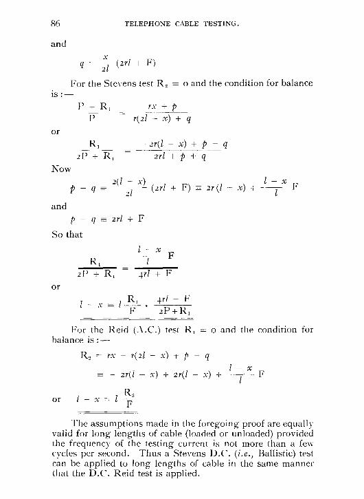
86 TELEPHONE CABLE TESTING.
and
q = 21
(2r1 + F)
For the Stevens test R2 = o and the condition for balance is :—
I ) + R, rx + p r(2I — x) + q
R, —27(1 — x) + p - q
2P + R, 2r/ + p + q
2(1 — x) q —= 21 (2r1 + F) 2r (I — x) +
pT q 2r1 + F
So that
R1
2P + R, 4r1 + F
or
1 — x = 1 R1 4r1 + F
F 2P +R1
For the Reid (A.C.) test R, = o and the condition for balance is
R, = rx — r(2I — x) + p - q
= — 27(1 — x) + 2r(1 — x) +
or 1 — x = I R, F
The assumptions made in the foregoing proof are equally valid for long lengths of cable (loaded or unloaded) provided the frequency of the testing current is not more than a few cycles per second. Thus a Stevens D.C. (i.e., Ballistic) test can be applied to long lengths of cable in the same manner that the D.C. Reid test is applied.
or
Now
and
I — x F
I — x F