tempest and red/black mechanical designsurflibrary.org/ses/tempest/tempestpapers/mechanical.pdf ·...
TRANSCRIPT

TEMPEST and RED/BLACK Mechanical Design
Bruce C. Gabrielson, PhD
Security Engineering Services PO Box 550
Chesapeake Beach, MD 20732 Introduction Not only general TEMPEST emission protection, but isolation between RED and BLACK circuit emissions must be considered at all levels from the circuit card to the system. Why is this? Since we are dealing with indirect paths, the mere fact that controls such as: circuit card separation, wires are individually shielded in a bundle, interface or power lines are passively filtered, currents are reduced through controlled impedances, or the entire subsystem is contained inside a conductive box, have been implemented is insufficient to guarantee that no problem signals will "leak outside or across the protected interface. Only through a diligent program to control emissions at each level of the design; system, rack, box, or circuit, can a "warm and fuzzy feeling" be gained that the sensitive information is well protected. After the fact protective efforts relying on strictly mechanical means to solve identified TEMPEST problems are both inefficient and extremely costly. The design options available for TEMPEST emission control include equipment redesign to reduce emission strength, internal shielding at the emission source, or complete enclosure on all internals emission sources in a conductive housing. This paper describes generic mechanical techniques used to control critical emissions in TEMPEST or COMSEC equipment. These same techniques, to varying degrees, might also be employed in the commercial world to control FCC noise emissions in high frequency data processing equipment. Strictly mechanical control methods are considered containment methods, while approaches that concentrate on circuit level controls are considered source suppression techniques. Proper design for emission control utilizes both control techniques. System to Rack to Box to Circuit Card Red/Black isolation at the system level is normally established using shielded enclosures or racks; physical separation or fiber optic applications of interconnect wires and equipment racks, and controlled power and ground systems. Red Equipment Areas (REA's) or Control Zones (CZ's) are used as the primary means of physically protecting the system from unauthorized access. At the system level, mechanical techniques are mostly concerned with providing lower impedance between each box in the system and the system ground then might exist in the system between boxes via other conductive paths. The system shown in Figure 1 describes a single conductive ground plane, with interconnected boxes solidly bonded to the plane with metal-to-metal contact. A single point power ground is used, with individual circuits floated and
1

grounded at only one point each. A conceptual TEMPEST block diagram of the system is shown in Figure 2. Various other available grounding approaches that can be used in multi-box systems are shown in Figure 3.
Figure 1 - Typical RED/BLACK System Layout
Figure 2 - Components of Secure System External Control and Power
2

Rack level RED/BLACK isolation is easiest to implement when all equipment in the rack is processing RED data (considered a RED node). RED and BLACK equipment can not be intermingled within one rack due to the multitude of grounds, power cables, and control/data lines that can be expected. Interconnect cables into or out of the rack should be shielded with metal connectors well grounded to the cable braid. Grooved and gasketed rack doors must remain closed, with conduit (if used instead of cables) leaving the rack solidly connected to the attachment point. The rack itself should be solidly grounded to facility ground, with power often isolated using an isolation transformer. Most TEMPEST mechanical protection techniques are applied at the box level. The chassis provides the overall, outer shielding. Covers are grooved and gasketed with torque requirements often recommended, view ports or holes are covered by conductive glass, mess screens, or use waveguide techniques, and control switches and indicators are isolated and often conductively shielded. Internal partitioning is required in most instances with power supplies usually considered first. COMSEC boxes have an internal physical RED/BLACK interface. The first layer of isolation at the pc card level is the power and ground configuration, followed by component location. If a motherboard is used, it also requires isolation, especially if it is used within a COMSEC box. Wire-wrapped boards should be avoided in preference to multilayer boards with outer ground layers and inner power planes.
Figure 3 - Grounding Approaches
Shielding The equipments outer housing provides the primary overall protection from internal TEMPEST emissions. Boxes can be all metal with welded sides, forged, dipped braised, or conductively coated plastic. Dipped braised housings are the preferred technique for COMSEC boxes as they can be configured to highly complicated and internally partitioned shapes at relatively low cost.
3

Conductive coated plastics are gaining in popularity, but have different maintenance, shielding effectiveness, and grounding problems then all metal housings. Table 1 shows available mixtures and coating types for plastic applications. The selection of shielding methodology involves evaluating the shielding required, the part design, pretreatment techniques, shielding material to be used and quality assurance to maintain coating consistency. Both spray on conductive adhesives (paints) and emersion type coatings are available. Table 2 is a comparison of the electrical properties of selected shielding methods.
Table 1
Available Mixtures and Coating Types For Plastics
Shielding RF
Zinc-Tin Spray Nickel filled Acrylic
Nickel filled Polyurethane Nickel filled Aqueous Polymer Graphite filled Acrylic
EMI Zinc-Tin Spray
Two-part Copper Epoxy Copolymer One-part Silver Acrylic
Conductive Adhesives
Two-part Copper Epoxy Copolymer \ One-part Copper Epoxy Copolymer
One of the biggest concerns with conductive coatings is their shielding effectiveness after extended high temperature and humidity (aging) testing. The results of a study on aging characteristics were published in the August 1988 issue of IEEE EMC Transactions. The testing program solidly demonstrated that certain environmental stresses would seriously degrade the shielding effectiveness of many coating materials. Significantly, if cost can be justified, only the zinc-arc type coatings provide extended shielding after long-term environmental exposure. TEMPEST and RED/BLACK Isolation at the Box Level Figure 4 is an expanded view of a TEMPEST Mechanical Workstation. Starting with the monitor, several mechanical controls are implemented. The cover plate is conductive, compressing a wire mesh impregnated glass screen and gasket to the monitor housing. Since the CRT display provides virtually an open hole for internal emissions to escape, some protective measures are always required.
4

Mesh impregnated glass is very popular and readily available for TEMPEST control applications, but has the problem of reducing visibility of the monitor screen. An expanded view of knitted wire mesh is shown in Figure 5. Conductive glass has lower shielding effectiveness properties, but also supplies greater visibility for light transfer. If conductive glass is used, or if a high-resolution monitor generates excessive noise, an additional approach is to reduce the internal emissions through the CRT with foil wrapping or by using an internal metal housing for the tube. Also, the wiring to the CRT driver board is often replaced with shielded wire, plus the internal boards themselves are provided with lower impedance ground straps.
Figure 4 - Expanded View of Conceptual Workstation
5

Gasketing A combination of gasketing, wave-guide groves, and torque restrictions are normally employed when solid metal-to-metal contact is insufficient for the particular application. Since gaskets have maintenance and life cycle requirements, they should only be used if other control means are ineffective, or if environmental restrictions are also imposed on the design. Figure 6 shows a typical application of tongue and groove design for a cover using a conductive gasket to provide both emission and environmental protection. Figure 7 shows the tongue and groove design for a typical side cover to chassis interface on a COMSEC 1/2 ATR type box.
Figure 5 - Knitted Wire Mesh Gasket
One type of gasket, metal fingerstock, is used extensively in shielding enclosure doors and to increase conductivity between enclosure components in metal computer housings that require either FCC of TEMPEST approval. While FCC requirements may dictate the use of one or two "fingers" at selected locations within the housing, TEMPEST requirements often dictate using metal stock around the entire circumference of the cover or opening. Although the fingers are resilient, they do often break and require replacement. Figure 4 showed a monitor mounted to a cover plate with uniform spaced screw holes. The effects of screw spacing on metal to metal cover contacts is shown in Figure 8. The key to screw spacing and torque requirements is the stiffness of the metal, and the allowable torque on the gasket. Over compression on a gasket will greatly reduce its shielding effectiveness.
Figure 6 - Tongue and Grove
Internal Partitioning Looking inside the chassis depicted in Figure 4, notice the power supply and printed circuit card cage are contained. This technique is commonly used in commercial TEMPEST designs when noise from individual cards is internally coupled to the power supply output lines. In this case,
6

the powerline filters were also separately filtered to prevent recoupling between the filter and the output wires.
Figures 9 through 19 show other internal partitioning concepts (including backplane) on COMSEC type boxes. In a COMSEC box, the intent is to isolate each section with respect to the other functional circuit sections. Red processing circuitry is physically isolated from Key variable processing circuitry, awell as from Black circuitry. Sinboth Red and Black power is required inside the box, the power system in also internally partitioned or otherwise isolated. The partitioning of the Key fill device in Figure 18 is intended to provide for tamper detect rather then emission protection.
s ce
k n, f the
a
Figure 7 - Tongue and Grove on 1/2 ATR
Some of the COMSEC units shown are 1/2 ATR configured. Notice that this configuration allows easy separation of Red and Blacfunctionality. In additionotice the attachment oisolated and partitioned motherboard in Figures 15 and 16. The use of a multi-layer sideboard with picket fence partitioning, as shownin the figures, provides the final unit with a complete isolation package since signals can be protected viphysical partitioning at the pc board, motherboard, and chassis level.
Figure 0 - Influence of Screw Spacing
Figure 19 shows an individual circuit card enclosed within a metal package. This technique is especially effective in cards that contain high frequency processing circuitry or video circuitry. The only limitation is cooling, which is sometimes accommodated with small waveguides or
7

holes to vent the heat. Some pc card added CCEP COMSEC devices use a similar approach for emission control and other reasons. Figure 20 shows an aluminum outer housing with interior partitions screwed in place. Aluminum is non-ferrous metal. Therefore, gaskets are normally used and nickel is sprayed on the interior of the box to enhance shielding. Conclusions Mechanical partitioning and shielding a box to control TEMPEST emissions represents a normally simple but expensive solution to the TEMPEST problem. It is containment at its highest level, and can be the fastest way to solve a variety of problems. However, unless the box is a straightforward design, making continuous mechanical modifications can ad significant delays and prototype costs to the overall program. References Gabrielson, B.C., RED/BLACK - A Description and Approach, Interference Technology Engineers Master, 1984. Amato, Jr., et al, Shielding Effectiveness of Conductive Coatings, IEEE Transactions on "EMC, Vol. 30, Number 3, August, 1988, pp 324 - 325.
Figure 9 - Cast Chassis Construction
8

Figure 10 - Typical COMSEC Partitioning
Figure 11 - Sideboard to Chassis Interface View 1
9

Figure 12 - Sideboard to Chassis View 2
Figure 13 - Sideboard Layout with Ground Barriers
10

Figure 14 - Mounted Sideboard and Picket Fence
Figure 15 - Internal Partitioning Showing Cards in Red and Black Inserter Perpendicular
11
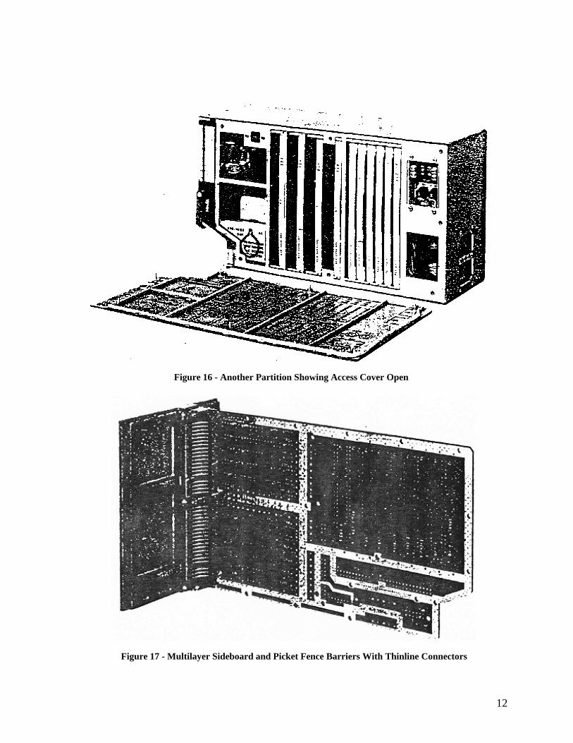
Figure 16 - Another Partition Showing Access Cover Open
Figure 17 - Multilayer Sideboard and Picket Fence Barriers With Thinline Connectors
12

Figure 18 - Key Fill Device
Figure 19 - Circuit Card Individually Encapsulated
13

Figure 20 - Aluminum Chassis With Internal Partitions (Usually Requires Nickel Coating on interior for Shielding)
14