terahertz radiation - dcujpm/ps407/terahertz.pdf · terahertz radiation colin rooney 14/12/00...
TRANSCRIPT
TERAHERTZ RADIATION
Colin Rooney 97002747Gillian Walsh 97637068
Terahertz Radiation Colin Rooney14/12/00 Gillian Walsh
2
1.0 INTRODUCTION
“…and then Apparent Banality stole Admiration from the Centre of Attention.”Gregor Wipf
This interesting quote is an apt and compact description of the arrival of terahertz radiation.Although it was hardly a mere arrival and much hard work and research lined the path to therealisation of T-rays, this apparently uninteresting snippet of the electromagnetic spectrum hasproven itself to be extremely beneficial. It has aroused the interest of more than thirty researchgroups across the globe and become a desirable source of radiation for many modern scientificapplications.Imaging technology is an important and widely used development in today’s society. X-rayscanners are found in most hospitals as well as ultrasound scanners and magnetic resonanceimaging machines. These conventional imaging techniques only use the extreme ends of theelectromagnetic spectrum.
The idea to exploit untouched regions of the electromagnetic spectrum is not a completely novel one.Extensive studies have been carried out on the visible and near-infrared regions of the spectrum, using avariety of laser-based techniques (such as fluorescence imaging and optical coherence tomography) forover a decade. However, the Rayleigh scattering of light has traditionally hindered the development ofoptical-based techniques. This scattering attenuates the light and blurs the image. Recently, there have beenefforts made to overcome this.As the amount of Rayleigh scattering is inversely proportional to the fourth power of the wavelength,
Ι(λ) = 2πckT/λ4
where Ι(λ) = intensity distributionc = speed of lightk = Boltzmann’s constantT = temperature
we expect the quality of the image to improve rapidly as we increase the wavelength and so obtain sharperimages at greater depths. However, conventional radiation sources produce microwaves with wavelengthsbetween a few millimetres and tens of centimetres. Such relatively long wavelengths limit the spatialresolution of the objects that can be discerned to around 5-mm, thereby precluding the use of microwavesin many applications. A wavelength small enough to provide good resolution, yet large enough to prevent
Fig 1.0 Electromagnetic Spectrum (Courtesy of Young and Freedman)

Terahertz Radiation Colin Rooney14/12/00 Gillian Walsh
3
serious losses by Rayleigh scattering, was required. Physicists looked to the so-called terahertz gap in theelectromagnetic spectrum – the region between 300 GHz and 20 THz in frequency. [1]In this paper we will attempt to give the reader a brief look at the original and most up-to-dategeneration, detection and amplification techniques of terahertz radiation, before documentingsome of its numerous and very beneficial applications.In Section 2.0, we address generation highlighting three methods only: the free-space electronLaser, terahertz antenna and Free-space electro-optic sampling. Although capable of emitting inthe far infrared, current requirements do not justify the complexity and expense of a FEL exceptfor experimental use. Both the photoconductive and FSEOS sources produce average powers thatrange from several nanowatts to tens of microwatts. These figures are moderate compared tothose of the FEL Photoconductive and FSEOS sources are, however, smaller, cheaper and morestable.In section 3.0, detection in terms of some of the above-mentioned methods is considered. Anothereffective detection method is the use of a helium-cooled bolometer which, however onlymeasures amplitude and not phase.In section 4.0, we briefly discuss the need for amplification of T-rays and the possibility of doingso with the help of constructive interference.A wide variety of applications are described in section 5.0 before finally focusing on the mainone - imaging in section 6.0.
2.0 GENERATION
2.1 Free-Space Electron Laser:Conventional lasers rely on the inversion of an atomic or molecular transition. Thus thewavelength at which they operate is determined by the active medium they use. The FELeliminates the atomic “middle-man”, and does not rely on specific transitions. Potentially FEL’soffer three main characteristics that are often hard to get with conventional lasers, namely widetunability, high power and high efficiency. They do this by using a relativistic beam of freeelectrons that interact with a periodic structure, typically in the form of a static magnetic field.This structure exerts a Lorentz force on the moving electrons, forcing them to oscillate.
Fig 2.0 Sketch of Free-electron laser
The basic idea is to cause all the electrons to have approximately the same phase, therebyproducing constructive interference (stimulated emission). A key feature of these lasers is that theemitted radiation is a function of the electron energy and we can change the wavelength of theFEL simply by the changing the energy of the electrons. The FEL is therefore a widely tuneablesystem and can be tuned to emit terahertz radiation [6].
Terahertz Radiation Colin Rooney14/12/00 Gillian Walsh
4
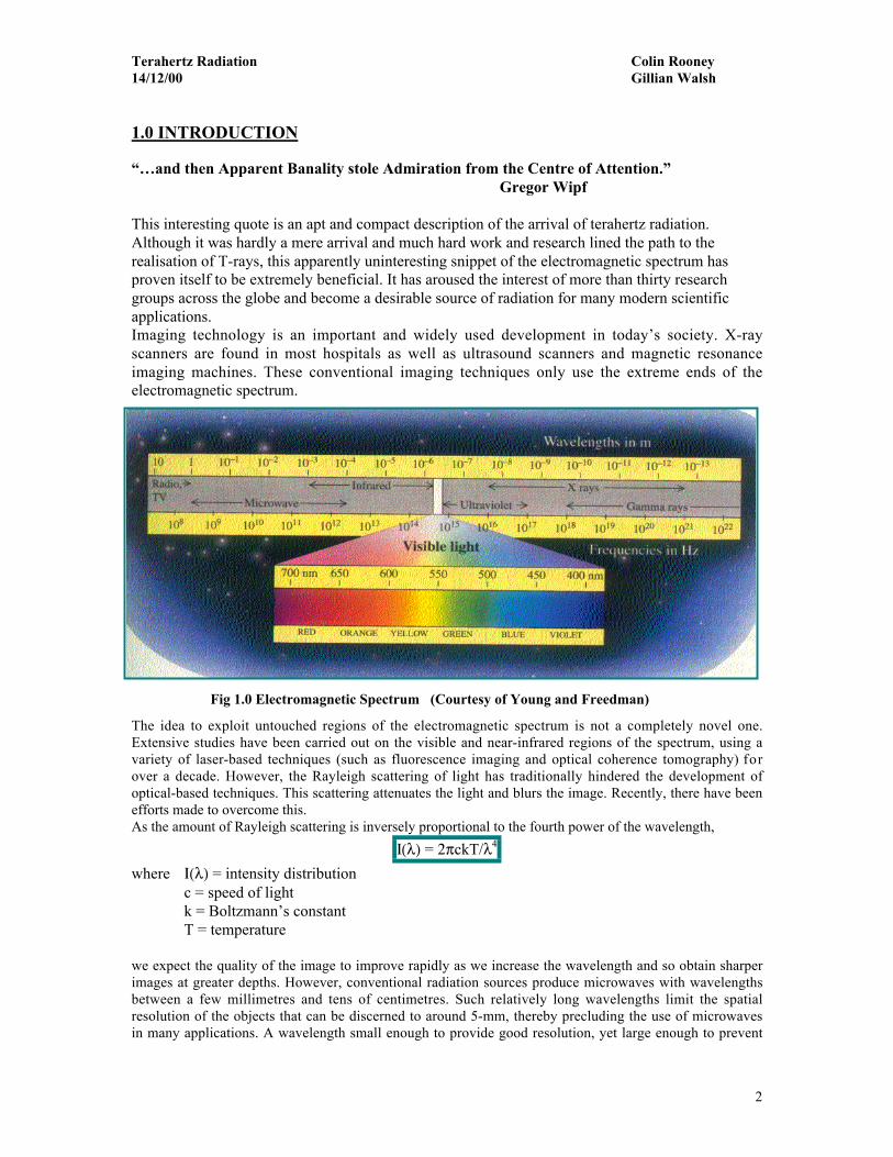
2.2 Photoconductive Dipole Antenna (PDA):The photoconductive dipole antenna was first described by Auston et al, and rapidly grew inpopularity among high-speed laser research groups around the globe [2].When a visible femtosecond pulse strikes a photoconductive emitter, such as a GaAs dipoleantenna, electron-hole pairs are generated in the semiconducting layer within the device [5]. Itcan be shown using Maxwell’s equations, that if a time-varying current is applied to theseparticles, electromagnetic waves will be emitted with an electric field, which is proportional tothe time derivative of this current. The emitted pulse will have no zero frequency component andhence the electric field will be a zigzag (zero-averaged). The pulse has a width of about 0.5 psand terahertz frequency [4]. A schematic diagram of this set-up is shown in Fig 2.1.
Fig 2.1Terahertz antenna
2.2 Free-Space Electro-Optic Sampling (FSEOS):This technique is based on emission by optical rectification. Optical rectification is a process firstobserved in the 1960’s that describes how a pulse at optical frequencies can be downshifted bydegenerate difference frequency generation inside a non-linear crystal.This effect arises from the second order susceptibility χ of a crystal. The susceptibility, χ=Ρ/ε0Εmeasures the degree of polarisation, Ρ, caused when an electric field, Ε, is applied to a dielectricmaterial (ε0 is the permittivity of a vacuum).The non-linearity between the polarisation, Ρ, and the magnitude of the electric field, Ε, may beencompassed by writing Ρas a power series in
Ρ = ε0 ( χ1Ε + χ2Ε + χ3Ε + .... )
Higher order terms such as χ2 , denote the non-linear response of the materials and are importantfor the high electric fields found in laser pulses. In a material subjected simultaneously to wavesof frequencies ω1 and ω2, the polarisation will contain a term of the form
cosω1t cosω2t = _ [cos(ω1 + ω2) + cos(ω1 − ω2)].
Terahertz Radiation Colin Rooney14/12/00 Gillian Walsh
5
Thus both sum and difference frequencies will be generated [15].Ultrafast pulses with a temporal width of approximately 70fs comprise a large number ofdifference frequency waves and have a frequency bandwidth in excess of 10THz. Using anultrafast visible pulse to excite a crystal that has large second-order susceptibility, such as zinctelluride, produces a time varying polarisation of the electron cloud inside the crystal. We canthink of the oscillating electron cloud with electric polarisation, Ρ, vibrating at the variousfrequencies (say ω1 and ω2 ) that correspond to those that make up the incident pulse of visiblelight. The electron cloud then re-radiates at terahertz frequencies, ωThz = ω1 + ω2 , as a result ofthe beats that form between the various frequency components. The pulse of terahertzelectromagnetic radiation contains a broad range of frequencies, from zero up to the bandwidth ofthe visible radiation [1].In contrast to PDA emission, the power of the terahertz pulse is derived entirely from the incidentlaser pulse, so FSEOS has typically lower power.
3.0 DETECTION
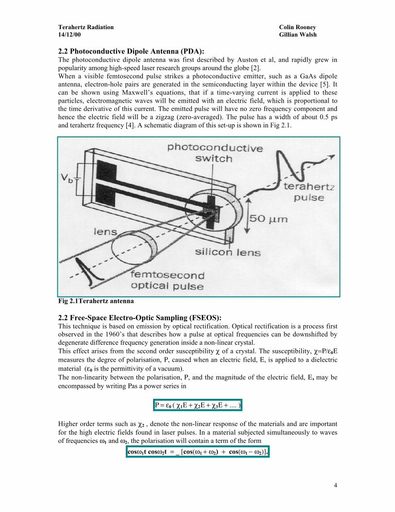
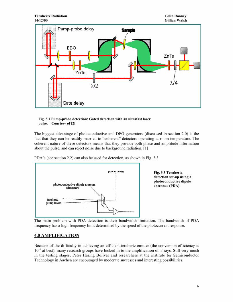
Detecting terahertz signals is difficult because blackbody radiation at room temperature is strongat terahertz frequencies. This can be overcome by using a helium-cooled bolometer, which isdesensitised to ambient temperature and registers only the heating effect of the terahertz radiation.The bolometer is an incoherent detector, registering only incident amplitude. Using a pump-probeconfiguration, on the other hand, allows for a far greater sensitivity and full coherent signalacquisition. [2,3]The pump-probe technique is used in terahertz systems, which include thosebased on photoconductive antennae, optical rectification and electro-optic detectors. Theseconcepts have been discussed in section 2.0. The pump-probe set-up shown in Fig. 3.0,demonstrates how two ultrafast pulses can be delayed relative to each other in time. The gateddetector operates only when illuminated by the probe pulse. The time resolution depends on theduration of the laser pulse and the cut-off speed of the detector.A clearer picture of pump-probe delay is shown in fig. 3.1. In this diagram the pulse is delayed ina way that produces a wavelength of λ/4.
Fig. 3.0 Example of pump-probe delay system. Courtesy of [4]
Terahertz Radiation Colin Rooney14/12/00 Gillian Walsh
6
The biggest advantage of photoconductive and DFG generators (discussed in section 2.0) is thefact that they can be readily married to “coherent” detectors operating at room temperature. Thecoherent nature of these detectors means that they provide both phase and amplitude informationabout the pulse, and can reject noise due to background radiation. [1]
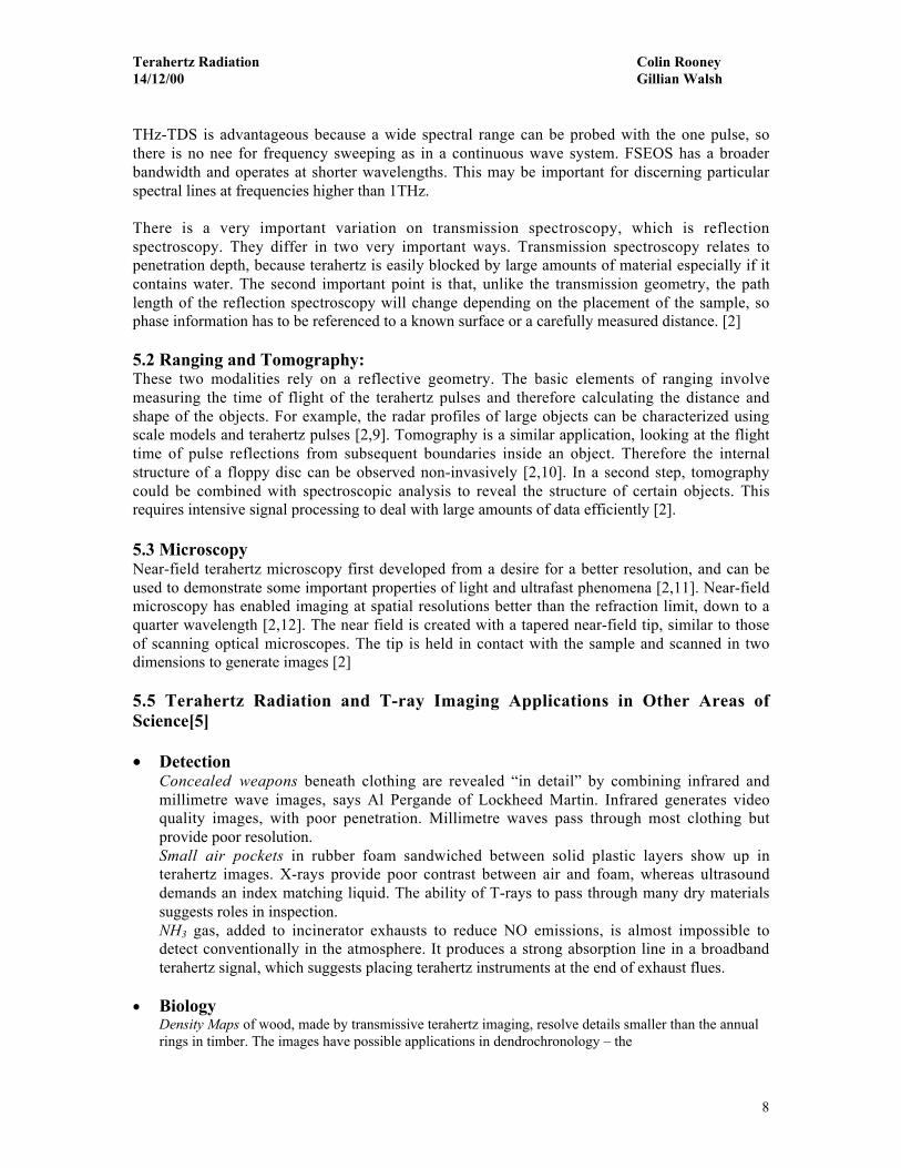
PDA’s (see section 2.2) can also be used for detection, as shown in Fig. 3.3
The main problem with PDA detection is their bandwidth limitation. The bandwidth of PDAfrequency has a high frequency limit determined by the speed of the photocurrent response.
4.0 AMPLIFICATION
Because of the difficulty in achieving an efficient terahertz emitter (the conversion efficiency is10-3 at best), many research groups have looked in to the amplification of T-rays. Still very muchin the testing stages, Peter Haring Bolívar and researchers at the institute for SemiconductorTechnology in Aachen are encouraged by moderate successes and interesting possibilities.
Fig. 3.1 Pump-probe detection: Gated detection with an ultrafast laserpulse. Courtesy of [2]
Fig. 3.3 Terahertzdetection set-up using aphotoconductive dipoleantennae (PDA)

Terahertz Radiation Colin Rooney14/12/00 Gillian Walsh
7
In attempting to amplify radiation generated in the processes mentioned above, the first instinct ofthe scientist would be to increase the power of the pump pulses. This is a false economy however,because the terahertz emitter rapidly reaches saturation as the electrons begin to dephase.One possible technique for increasing the power of terahertz emissions which is presently underinvestigation by Peterbeing investigis by non-inversion amplification [5].As the intensity of the terahertz pulse is proportional to the square of its electrical field, it may bepossible to amplify pulses by twice the product of their electric fields with constructiveinterference.A terahertz emitter is placed in a 4m long ring resonator and is exposed to a train of femtosecondpulses from a laser running at 76Mhz. Every time an optical pulse strikes the emitter a terahertzpulse travels around the resonator.Each pulse arrives back at the emitter just as the next optical pulse generates another terahertzemission. The electrical fields of the two-terahertz pulses combine and their energies multiplyaccording to the formula
212
22
12
21 2)( EEEEEEI ++=+≈
Another possible future method of amplification which has not yet been realised involves beamsplitting. Bolívar and his team are looking onto this at the moment
5.0 APPLICATIONS
Terahertz radiation is mostly used in observation rather than physical manipulation. It has a widevariety of applications and possible applications. Imaging remains the most fervently researchedand eagerly awaited application of T-rays. T-rays have, however, also become an importantaddition to such areas as spectroscopy, range finding, tomography and microscopy. We willconsider these applications in some detail.Terahertz spectroscopy is valuable for distinguishing molecules and studying intermolecularinteractions, while tomography relates to imaging through the successive layers of a material.Microscopy with T-rays is realised by working in the near-field terahertz radiation pattern, thusovercoming the far-field wavelength limitation on resolution.There exists a further uncountable number of applications for T-rays and even a brief descriptionof these would be ambitious. We have therefore opted to give a bullet-point review of some of themore interesting applications in biology, chemistry, gas detection, medicine and elsewhere beforegiving a more comprehensive account of T-ray imaging.
5.1 Spectroscopy:Terahertz spectroscopy is based on observing changes in the terahertz spectrum after transmissionthrough or reflection from a material, the most common terahertz spectroscopy system beingterahertz time-domain spectroscopy (THz-TDS) [2,7]. THz-TDS relies on PDA detection andemission technology. In its most simplistic form, the Fourier spectrum of a free–space terahertzpulse is first characterised, then compared to the spectrum of a pulse that already has passedthrough some sample. The difference between the two spectra reveals the sample’s molecularabsorption lines. THz-TDS has been said to measure the refractive indexes of many differentsubstances like dielectrics, semiconductors and liquids. Also it has been used in recognising gasesin and in observing the rotational absorption spectra of hot water vapour in flames. One of themore interesting features of spectroscopy is that in the far infrared because one can study thechemical reactions, which is very important in understanding how chemical and biologicalsystems operate and interact [2,8].
Terahertz Radiation Colin Rooney14/12/00 Gillian Walsh
8
THz-TDS is advantageous because a wide spectral range can be probed with the one pulse, sothere is no nee for frequency sweeping as in a continuous wave system. FSEOS has a broaderbandwidth and operates at shorter wavelengths. This may be important for discerning particularspectral lines at frequencies higher than 1THz.
There is a very important variation on transmission spectroscopy, which is reflectionspectroscopy. They differ in two very important ways. Transmission spectroscopy relates topenetration depth, because terahertz is easily blocked by large amounts of material especially if itcontains water. The second important point is that, unlike the transmission geometry, the pathlength of the reflection spectroscopy will change depending on the placement of the sample, sophase information has to be referenced to a known surface or a carefully measured distance. [2]
5.2 Ranging and Tomography:These two modalities rely on a reflective geometry. The basic elements of ranging involvemeasuring the time of flight of the terahertz pulses and therefore calculating the distance andshape of the objects. For example, the radar profiles of large objects can be characterized usingscale models and terahertz pulses [2,9]. Tomography is a similar application, looking at the flighttime of pulse reflections from subsequent boundaries inside an object. Therefore the internalstructure of a floppy disc can be observed non-invasively [2,10]. In a second step, tomographycould be combined with spectroscopic analysis to reveal the structure of certain objects. Thisrequires intensive signal processing to deal with large amounts of data efficiently [2].
5.3 MicroscopyNear-field terahertz microscopy first developed from a desire for a better resolution, and can beused to demonstrate some important properties of light and ultrafast phenomena [2,11]. Near-fieldmicroscopy has enabled imaging at spatial resolutions better than the refraction limit, down to aquarter wavelength [2,12]. The near field is created with a tapered near-field tip, similar to thoseof scanning optical microscopes. The tip is held in contact with the sample and scanned in twodimensions to generate images [2]
5.5 Terahertz Radiation and T-ray Imaging Applications in Other Areas ofScience[5]
• DetectionConcealed weapons beneath clothing are revealed “in detail” by combining infrared andmillimetre wave images, says Al Pergande of Lockheed Martin. Infrared generates videoquality images, with poor penetration. Millimetre waves pass through most clothing butprovide poor resolution.Small air pockets in rubber foam sandwiched between solid plastic layers show up interahertz images. X-rays provide poor contrast between air and foam, whereas ultrasounddemands an index matching liquid. The ability of T-rays to pass through many dry materialssuggests roles in inspection.NH3 gas, added to incinerator exhausts to reduce NO emissions, is almost impossible todetect conventionally in the atmosphere. It produces a strong absorption line in a broadbandterahertz signal, which suggests placing terahertz instruments at the end of exhaust flues.
• BiologyDensity Maps of wood, made by transmissive terahertz imaging, resolve details smaller than the annualrings in timber. The images have possible applications in dendrochronology – the
Terahertz Radiation Colin Rooney14/12/00 Gillian Walsh
9
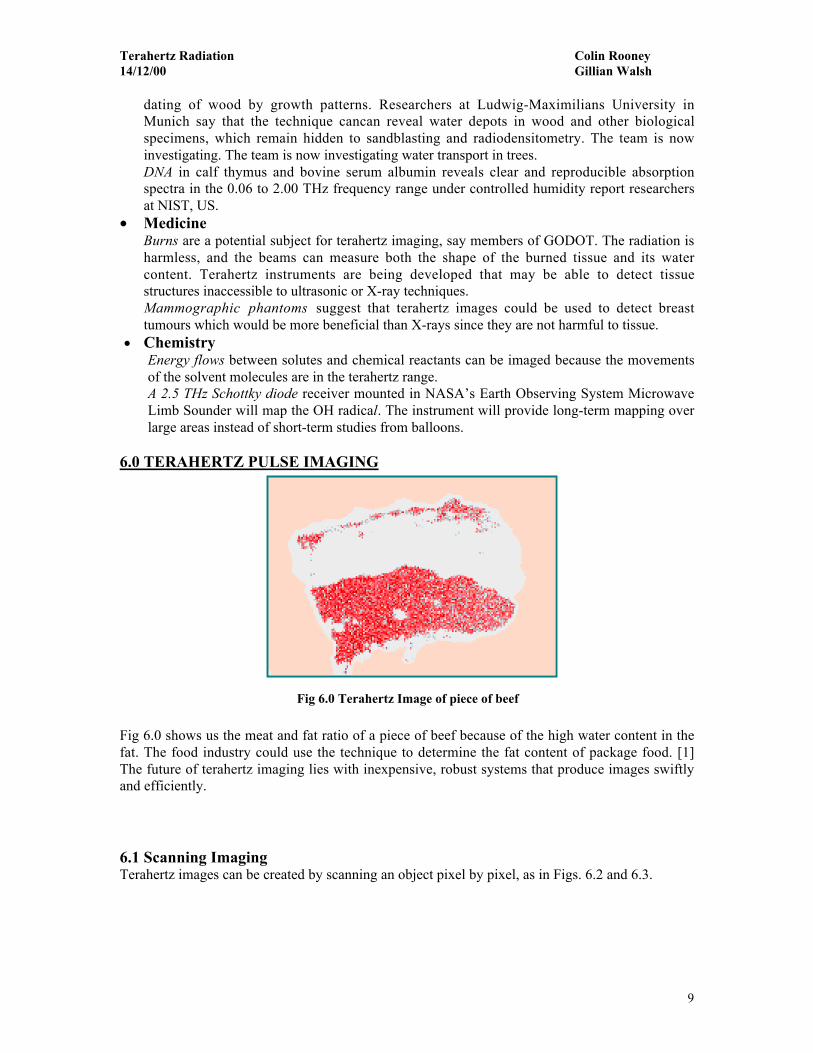
Fig 6.0 Terahertz Image of piece of beef
dating of wood by growth patterns. Researchers at Ludwig-Maximilians University inMunich say that the technique cancan reveal water depots in wood and other biologicalspecimens, which remain hidden to sandblasting and radiodensitometry. The team is nowinvestigating. The team is now investigating water transport in trees.DNA in calf thymus and bovine serum albumin reveals clear and reproducible absorptionspectra in the 0.06 to 2.00 THz frequency range under controlled humidity report researchersat NIST, US.
• MedicineBurns are a potential subject for terahertz imaging, say members of GODOT. The radiation isharmless, and the beams can measure both the shape of the burned tissue and its watercontent. Terahertz instruments are being developed that may be able to detect tissuestructures inaccessible to ultrasonic or X-ray techniques.Mammographic phantoms suggest that terahertz images could be used to detect breasttumours which would be more beneficial than X-rays since they are not harmful to tissue.
• ChemistryEnergy flows between solutes and chemical reactants can be imaged because the movementsof the solvent molecules are in the terahertz range.A 2.5 THz Schottky diode receiver mounted in NASA’s Earth Observing System MicrowaveLimb Sounder will map the OH radical. The instrument will provide long-term mapping overlarge areas instead of short-term studies from balloons.
6.0 TERAHERTZ PULSE IMAGING
Fig 6.0 shows us the meat and fat ratio of a piece of beef because of the high water content in thefat. The food industry could use the technique to determine the fat content of package food. [1]The future of terahertz imaging lies with inexpensive, robust systems that produce images swiftlyand efficiently.
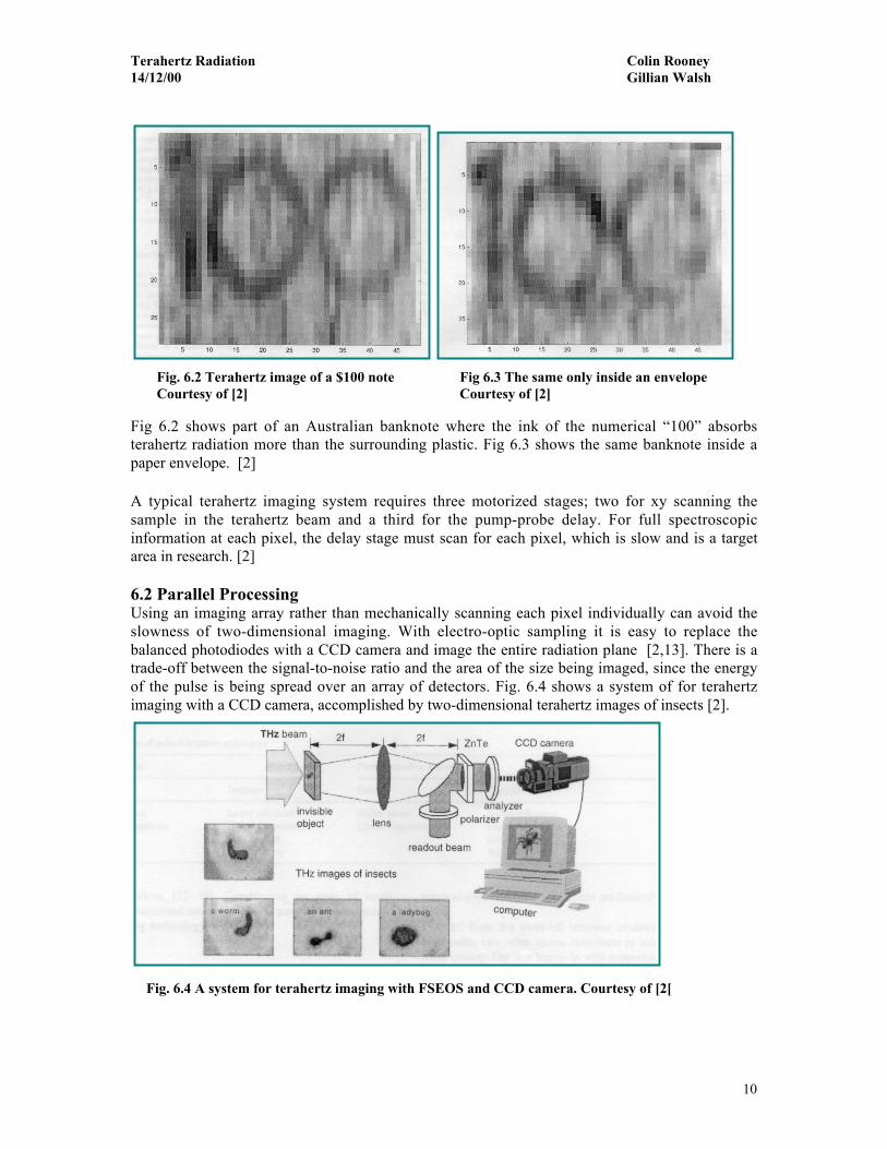
6.1 Scanning ImagingTerahertz images can be created by scanning an object pixel by pixel, as in Figs. 6.2 and 6.3.
Terahertz Radiation Colin Rooney14/12/00 Gillian Walsh
10
Fig 6.3 The same only inside an envelopeCourtesy of [2]
Fig 6.2 shows part of an Australian banknote where the ink of the numerical “100” absorbsterahertz radiation more than the surrounding plastic. Fig 6.3 shows the same banknote inside apaper envelope. [2]
A typical terahertz imaging system requires three motorized stages; two for xy scanning thesample in the terahertz beam and a third for the pump-probe delay. For full spectroscopicinformation at each pixel, the delay stage must scan for each pixel, which is slow and is a targetarea in research. [2]
6.2 Parallel ProcessingUsing an imaging array rather than mechanically scanning each pixel individually can avoid theslowness of two-dimensional imaging. With electro-optic sampling it is easy to replace thebalanced photodiodes with a CCD camera and image the entire radiation plane [2,13]. There is atrade-off between the signal-to-noise ratio and the area of the size being imaged, since the energyof the pulse is being spread over an array of detectors. Fig. 6.4 shows a system of for terahertzimaging with a CCD camera, accomplished by two-dimensional terahertz images of insects [2].
Fig. 6.2 Terahertz image of a $100 noteCourtesy of [2]
Fig. 6.4 A system for terahertz imaging with FSEOS and CCD camera. Courtesy of [2[
Terahertz Radiation Colin Rooney14/12/00 Gillian Walsh
11
An important disadvantage of CCD imaging is the loss of the lock-in amplifier, which normallyprovides cancellation of the 1/f laser noise. [2]
The benefit of two-dimensional parallel processing has not yet been realised withphotoconductive antennae. An array of PDA’s would be far less sensitive to laser noise than aCCD based on electro-optic detection, and laser noise dominates an electro-optic system. [2,14]
7.0 CONCLUSION
Terahertz imaging is becoming a more recognised imaging technique, which is still at the earlystages of development. T-rays are non-invasive to human (and other) tissue, and exposure toTerahertz radiation has no detrimental effects. Terahertz imaging is set to replace to X-rays andCT scans. Banks and retailers are contemplating a large-scale use of T-rays for currency countingand differentiation. Although still in the early unruly years of its development terahertz sciencehas made a dazzling entrance and means to continue in a similar style.
Terahertz Radiation Colin Rooney14/12/00 Gillian Walsh
12
8.0 REFERENCES
[1] Terahertz imaging comes into view - Don Arnone, Craig Ciesla and Michael Pepper[2] Analysis of system trade-offs for terahertz imaging, S. Mickan, D. Abbott, J. Munch, X.-
C.Zhang, T.van Dooen, Elsevier Science Ltd.[3] J.A. Valdmanis, G. Mourou, C.W. Gabel, Picosecond electro-optic sampling system,
Applied Physics Letters 41 (3) (1982) 211-212[4] GODOT’S home page http://dutch.phys.strath.ac.uk/THz/[5] Terahertz rays ready to track microscale phenomena – John Bell, OLE Dec.1998[6] Elements of Quantum optics (1990) – Meytre, P. and Sargent III, M.[7] Q. Wu, T.D. Hewitt, X.-C Zhang, Two dimensional electro-optic imaging of terahertz
beams, Applied Physics letters 69 (8) (1996) 1026-1028[8] B.N Flanders, D.C. Arnett, N.F. Scherer, optical pump-terahertz probe spectroscopy
utilizing a cavity-duped oscillator-driven terahertz spectrometer, IEEE Journel ofSelected Topics in Quantum Electronics 4 (2) (1998) 353-359
[9] R.A. Chellive, D. Grishkowsky, Time-Domain terahertz impulse ranging studies, appliedPhysics Letters 67 (14) (1995) 1960-1962
[10] D.M Mittleman, R. Neelamani, R.G. Baraniuk, M.C. Nuss, Applications of terahertzimaging, in: Nonlinear Optics 98: Materials, Fundamentals and Applications TopicalMeeting, IEEE, Princeville, HI, 1998, pp. 294-296
[11] K. Wynne, J.C Carey, J Zawadzka, D.A. Jaroszynski, Superluminal propagation ofterahertz pulses in sub-wavelength structures, in: Conference of Laser and Electro-Optics`99, IEEE LEOS OSA, Baaltimore, MD, 1999, p.397
[12] S. Hunsch, M. Koch, I. Brener, M.C. Nuss, Terahertz near-field imaging, OpticsCommunications 150 (1998) 22-26
[13] D.A.R.P. Agency, Electronics technology office: solicitations: Baa 95-15http://www.darpa.mil/ETO/Solicitations/BAA99-15/S/Section1.htm1
[14] Y. Cai, I Brener, J. Lopata, J. Wynn, L Pfeiffer, J. B. Stark, Q. Wu, X-C Zhang, J.Federici, Coherent terahertz detection: Direct comparison between free-space electrooptic sampling and antenna detection, Applied Physics Letters 73 (4) (1998) 444-446
[15] O. S. Heavens and R. W. Ditchburn - Insight into Optics (1987)