testconx 2020 presentation yukang (dylan) feng · testconx 2020 over the air test solution for new...
TRANSCRIPT

Over the Air Test Solution for New 5G / mm-Wave Band Wireless ICsTestConX 2020Session 2 Presentation 3
May 11-13, 2020TestConX Workshop www.testconx.org
Over the Air Test Solution for
New 5G / mm-Wave Band Wireless ICs
Yukang (Dylan) FengStaff RF Development EngineerCohu Interface Solution Group
Virtual Event ● May 11-13, 2020

Over the Air Test Solution for New 5G / mm-Wave Band Wireless ICsTestConX 2020Session 2 Presentation 3
May 11-13, 2020TestConX Workshop www.testconx.org
Contents• Overview of AiP-based wireless IC technology• 5G & mm-Wave wireless ICs: New Standard• OTA test solutions for 5G / mm-Wave ICs• OTA test solution: Lab Measurement • Conclusions
Over the Air Test Solution for New 5G / mmWave Band Wireless ICs 2

Over the Air Test Solution for New 5G / mm-Wave Band Wireless ICsTestConX 2020Session 2 Presentation 3
May 11-13, 2020TestConX Workshop www.testconx.org
Overview of AiP-based wireless IC technology
Over the Air Test Solution for New 5G / mmWave Band Wireless ICs 3
Akanksha Bhutani 122 GHz aperture-coupled stacked patch microstrip antenna in LTCC technology 2016 10th European Conference on Antennas and Propagation (EuCAP)
Antenna-in-Package (AiP) solution:• The AiP solution is a combination of an antenna or
antenna array with an RFIC die into a standard chip scale package
• Compared to traditional RFIC mounted on a PCB, AiPhas higher integration scale and smaller parasitics.
• The packaging material could be high-resistivity silicon, Teflon, ceramics (or low temperature cofired ceramic), or polymers (like liquid crystal polymer) [1][2]
Classic AiP PackagingTraditional 4G Circuit Board
https://www.eenewsembedded.com/news/4g-lte-%E2%80%98maker%E2%80%99-m2m-modem-project-hosts-u-blox-module
https://www.computerworld.com/article/3166554/5g-starts-with-chips-like-ibm-and-ericssons-silicon-antenna.html

Over the Air Test Solution for New 5G / mm-Wave Band Wireless ICsTestConX 2020Session 2 Presentation 3
May 11-13, 2020TestConX Workshop www.testconx.org
Overview of AiP-based wireless IC technology• 5G era ICs functions in much higher frequency
• Pre-5G wireless IC technology limitations1) Have low antenna gain (directivity)2) Only provide linear polarization3) Have high power consumption
Over the Air Test Solution for New 5G / mmWave Band Wireless ICs 4
4G LTE 5G Mid Band
5G “mm” Band
5G radar Band
Not fit for 5G applications

Over the Air Test Solution for New 5G / mm-Wave Band Wireless ICsTestConX 2020Session 2 Presentation 3
May 11-13, 2020TestConX Workshop www.testconx.org
5G & mm-Wave wireless ICs: New Standard
• Any wireless transmission loss subjects to same ruleFree Space Path Loss (FSPL):
4G application, single patch antenna Gain ~ 5 - 7 dB From 2.8 GHz to 28 GHz, FSPL increases 10 dB 5G wireless ICs typically have higher gain antenna
Over the Air Test Solution for New 5G / mmWave Band Wireless ICs 5
1. Needs much higher gain (directivity)

Over the Air Test Solution for New 5G / mm-Wave Band Wireless ICsTestConX 2020Session 2 Presentation 3
May 11-13, 2020TestConX Workshop www.testconx.org
• Electric phase shift control: steering radiation direction and forming a narrow beam
• High gain and directivity: typical array as small as four antennas can provide 15 - 20 dB gain
• Shorter communication distance: effective communication distance is hundreds of feet instead of several miles;
5G & mm-Wave wireless ICs: New Standard
Over the Air Test Solution for New 5G / mmWave Band Wireless ICs 6
2. widely applying antenna array
8x8 antenna array

Over the Air Test Solution for New 5G / mm-Wave Band Wireless ICsTestConX 2020Session 2 Presentation 3
May 11-13, 2020TestConX Workshop www.testconx.org
5G & mm-Wave wireless ICs: New Standard
3. widely use antenna circular polarization
Over the Air Test Solution for New 5G / mmWave Band Wireless ICs 7
electric field vectors of a traveling circularly-polarized electromagnetic wave
picture from Wikipedia
electric and magnetic field in linear polarized EM wave
picture from Wikimedia
• Wide tolerance on antenna alignment
• Resistive to signal magnitude degradation
• Less susceptible to Faraday Effect
circular polarization advantages

Over the Air Test Solution for New 5G / mm-Wave Band Wireless ICsTestConX 2020Session 2 Presentation 3
May 11-13, 2020TestConX Workshop www.testconx.org
OTA test solutions for 5G / mm-Wave ICs
Over the Air Test Solution for New 5G / mmWave Band Wireless ICs 8
• Contactor antenna needs wideband RF performance in high frequency• Contactor antenna must radiate uniformly in whole antenna array• Contactor antenna must be adaptable to linear / circular polarized
radiation• Contactor must provide low loss & ultra-wide band signal interface
New IC test requirement: Summary

Over the Air Test Solution for New 5G / mm-Wave Band Wireless ICsTestConX 2020Session 2 Presentation 3
May 11-13, 2020TestConX Workshop www.testconx.org
Solutions for 5G / mm-Wave OTA Test
• RF test signal is feed to the DUT through contactor antenna
• Contactor antenna radiates uniformly DUT antenna array
• Contactor antenna radiation covers 5G frequency band (23–30 GHz & 38 – 45 GHz)
• Contactor antenna and DUT antenna couple in far field region
• DUT is installed in a wide band low loss test socket during test
• DUT outputs RF signal through high performance signal route (spring probe or xWave solution)
• Contactor input / output sampled by VNA S-parameter analysis
Over the Air Test Solution for New 5G / mmWave Band Wireless ICs 9
5G / mm-wave OTA IC contactor features

Over the Air Test Solution for New 5G / mm-Wave Band Wireless ICsTestConX 2020Session 2 Presentation 3
May 11-13, 2020TestConX Workshop www.testconx.org
Solutions for 5G / mm-Wave OTA Test
Over the Air Test Solution for New 5G / mmWave Band Wireless ICs 10
Waveguide RF chokePatch antennafor DUT top patch antennae
Waveguide antenna forend-fire dipole on DUT
Contactor Diagram (cross-section view) RF Feeding / power grid to DUT
DUT
Patch Antenna
DUT RF Feeding / PCB
Wave guide
Load Plate

Over the Air Test Solution for New 5G / mm-Wave Band Wireless ICsTestConX 2020Session 2 Presentation 3
May 11-13, 2020TestConX Workshop www.testconx.org
Solutions for 5G / mm-Wave OTA Test
Over the Air Test Solution for New 5G / mmWave Band Wireless ICs 11
• Contactor antenna design guidelineAntenna Gain is given by:
𝐺𝑎𝑖𝑛 dB 10 ∙ log 4π𝑆λ ∙ ηη is the antenna efficiency, S is antenna aperture sizeBigger aperture provides bigger gain
-3dB Beam width θ is estimated:𝐺𝑎𝑖𝑛 - 𝐺𝑎𝑖𝑛 = 3dB; θ 2 ∙ tanIn practice, we find:Bigger aperture gives narrower beam
𝑹𝟏𝑳

Over the Air Test Solution for New 5G / mm-Wave Band Wireless ICsTestConX 2020Session 2 Presentation 3
May 11-13, 2020TestConX Workshop www.testconx.org
Solutions for 5G / mm-Wave OTA Test
Over the Air Test Solution for New 5G / mmWave Band Wireless ICs 12
• Contactor antenna design guideline
𝑹𝟏𝑳
• For example, contactor antenna with -3 dB beam width 60°
• DUT antenna array diameter: 14mm diagonal
• Antenna coupling distance L:L = 7/ tan(30°) ≈ 12mm
Over the Air Test Solution for New 5G / mm-Wave Band Wireless ICsTestConX 2020Session 2 Presentation 3
May 11-13, 2020TestConX Workshop www.testconx.org
Solutions for 5G / mm-Wave OTA Test
Over the Air Test Solution for New 5G / mmWave Band Wireless ICs 13
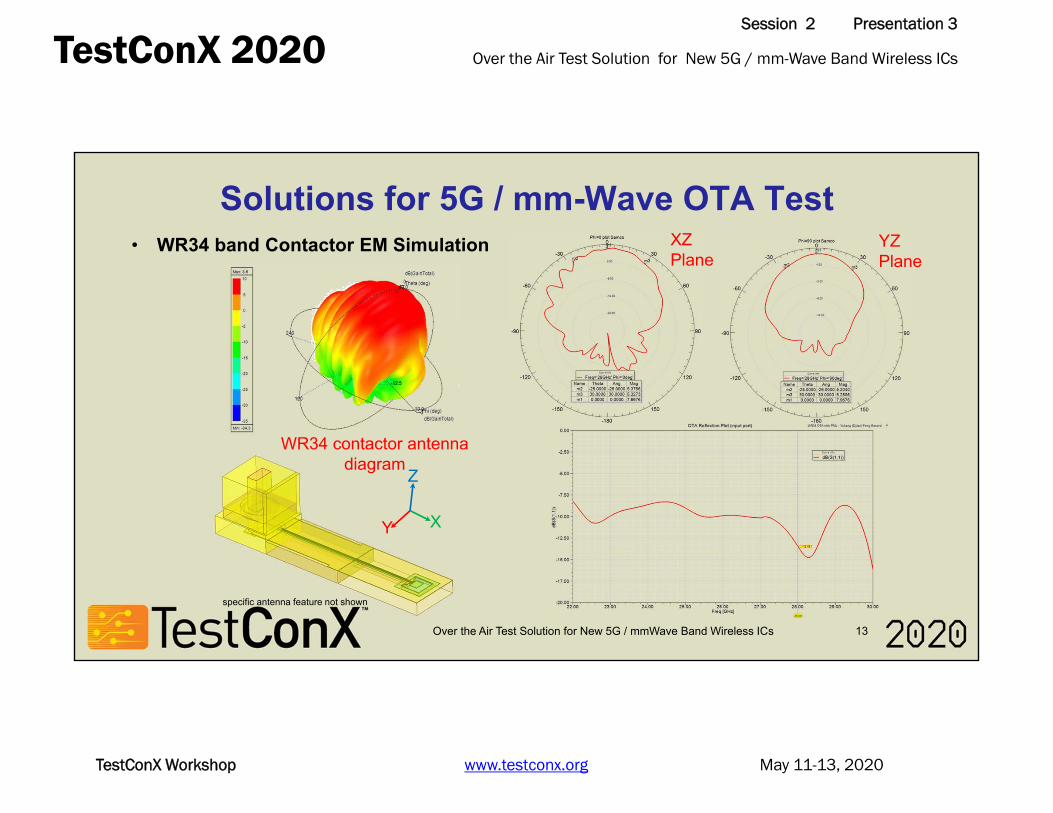
• WR34 band Contactor EM Simulation
WR34 contactor antenna diagram
YZ Plane
XZ Plane
Z
Y X
specific antenna feature not shown
Over the Air Test Solution for New 5G / mm-Wave Band Wireless ICsTestConX 2020Session 2 Presentation 3
May 11-13, 2020TestConX Workshop www.testconx.org
Solutions for 5G / mm-Wave OTA Test
Over the Air Test Solution for New 5G / mmWave Band Wireless ICs 14
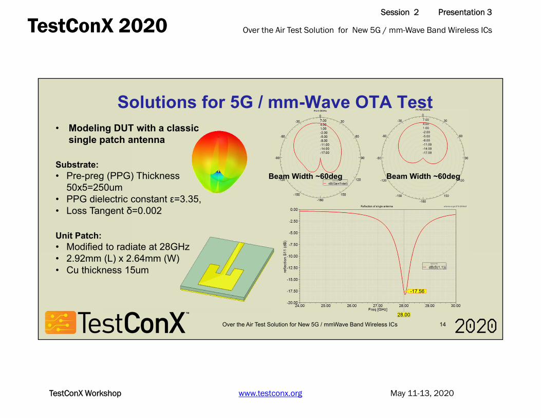
• Modeling DUT with a classic single patch antenna
Substrate:• Pre-preg (PPG) Thickness
50x5=250um• PPG dielectric constant ε=3.35, • Loss Tangent δ=0.002
Unit Patch: • Modified to radiate at 28GHz• 2.92mm (L) x 2.64mm (W)• Cu thickness 15um
Beam Width ~60deg Beam Width ~60deg

Over the Air Test Solution for New 5G / mm-Wave Band Wireless ICsTestConX 2020Session 2 Presentation 3
May 11-13, 2020TestConX Workshop www.testconx.org
Solutions for 5G / mm-Wave OTA Test
Over the Air Test Solution for New 5G / mmWave Band Wireless ICs 15
• Radiation Uniformity & Beam Width Evaluation
Conditions:• Four identical 28GHz patch antennas forming an array• 5.4 mm away from each other over a 20 mm range• Each antenna has an individual port (port 2-5)
Result:• Contactor and DUT antennas have trivial reflection• Energy delivery ratio S21 > -28 dB at 20 mm distance• Difference on each antenna’s S21 < 2dB
specific antenna feature not shown
Port 1
Port 2-5

Over the Air Test Solution for New 5G / mm-Wave Band Wireless ICsTestConX 2020Session 2 Presentation 3
May 11-13, 2020TestConX Workshop www.testconx.org
Solutions for 5G / mm-Wave OTA Test
Over the Air Test Solution for New 5G / mmWave Band Wireless ICs 16
Transition Region Far Field RegionNear Field Region1 λ
At 28 GHz, λ = 10.7 mm, according to Friis’ Equation (Far Field)𝑃𝑃 𝐷𝑡𝐷 𝜆4𝜋𝑑
Antenna Distance (mm)
S21 Calculation(dB)
10 -22.020 -28.030 -31.560 -37.5
EM simulation result using HFSS
Antenna Distance (mm)
S21
(dB)
-40-35-30-25-20-15-10
-50
0 20 40 60 80
S21 Simulation(dB)-22.8-28.1-30.8-36.1
• Determinate Contactor Antenna & DUT Distance
Over the Air Test Solution for New 5G / mm-Wave Band Wireless ICsTestConX 2020Session 2 Presentation 3
May 11-13, 2020TestConX Workshop www.testconx.org
Over the Air Test Solution for New 5G / mmWave Band Wireless ICs 17
Solutions for 5G / mm-Wave OTA Test
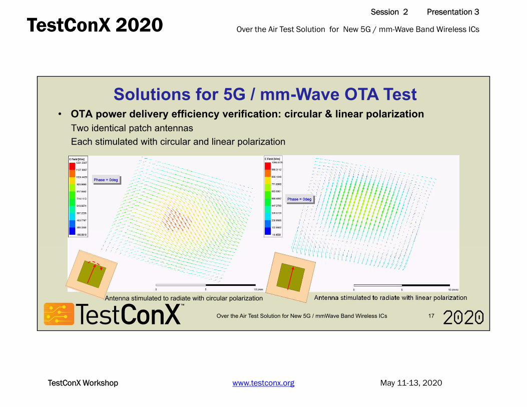
Antenna stimulated to radiate with circular polarization
Antenna stimulated to radiate with linear polarization
• OTA power delivery efficiency verification: circular & linear polarizationTwo identical patch antennasEach stimulated with circular and linear polarization
Antenna stimulated to radiate with circular polarization
Over the Air Test Solution for New 5G / mm-Wave Band Wireless ICsTestConX 2020Session 2 Presentation 3
May 11-13, 2020TestConX Workshop www.testconx.org
Over the Air Test Solution for New 5G / mmWave Band Wireless ICs 18
Solutions for 5G / mm-Wave OTA Test
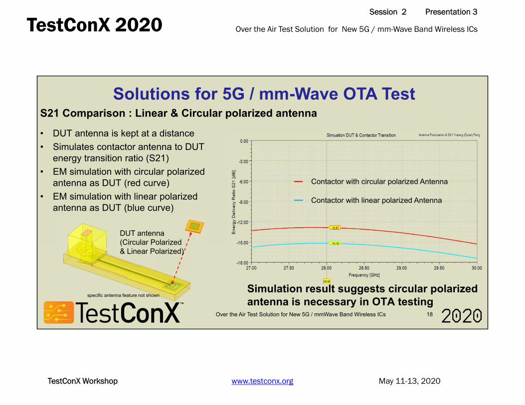
• DUT antenna is kept at a distance• Simulates contactor antenna to DUT
energy transition ratio (S21)• EM simulation with circular polarized
antenna as DUT (red curve)• EM simulation with linear polarized
antenna as DUT (blue curve)
Contactor with circular polarized Antenna
Contactor with linear polarized Antenna
S21 Comparison : Linear & Circular polarized antenna
DUT antenna(Circular Polarized & Linear Polarized)
Simulation result suggests circular polarized antenna is necessary in OTA testing
specific antenna feature not shown

Over the Air Test Solution for New 5G / mm-Wave Band Wireless ICsTestConX 2020Session 2 Presentation 3
May 11-13, 2020TestConX Workshop www.testconx.org
Solutions for 5G / mm-Wave OTA Test
Over the Air Test Solution for New 5G / mmWave Band Wireless ICs 19
GSG S12 SimulationGSG S22 SimulationGSSG S12 SimulationGSSG S22 Simulation
GS S12 SimulationGS S22 SimulationGSG S12 MeasurementGSG S22 Measurement
Spring probe / PCB Solution
Lead Frame
Lead-frame RF & spring probe DC
DC/IF Pins
• Cohu’s Pogo solution provides wideband & low loss performance till 67 GHz
• xWave leadframe technology provides higher band RF connection in 60+ GHz band
• xWave technology uses a 3-D transmission metal trace directly routes the RF signal from coaxial connection (2.92 mm / 1.85 mm connector) to DUT with minimum parasitic inductance / capacitance and wide bandwidth
xWave Technology: Low Loss RF Contact in 80GHz+ Band
Over the Air Test Solution for New 5G / mm-Wave Band Wireless ICsTestConX 2020Session 2 Presentation 3
May 11-13, 2020TestConX Workshop www.testconx.org
Over the Air Test Solution for New 5G / mmWave Band Wireless ICs 20
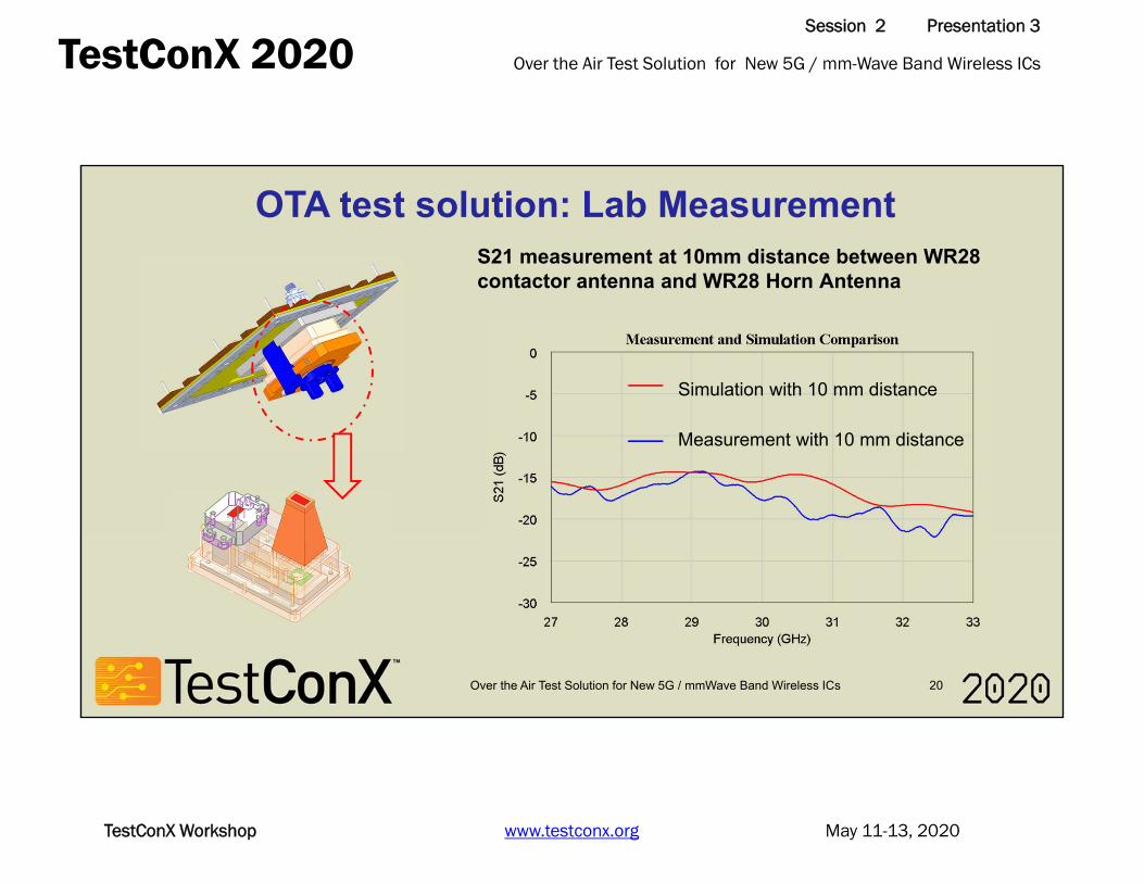
Simulation with 10 mm distance
Measurement with 10 mm distance
OTA test solution: Lab Measurement S21 measurement at 10mm distance between WR28 contactor antenna and WR28 Horn Antenna

Over the Air Test Solution for New 5G / mm-Wave Band Wireless ICsTestConX 2020Session 2 Presentation 3
May 11-13, 2020TestConX Workshop www.testconx.org
Conclusions
Over the Air Test Solution for New 5G / mmWave Band Wireless ICs 21
• In 5G & mm-wave Era, wireless ICs work in much higher band, which requires higher antenna gain and electrical beam steering.
• Phase array has became a new standard in wireless IC design• To test 5G wireless ICs, contactor antenna needs to provide wide beam
width and uniform radiation• To coordinate widely used circular polarization DUT antenna array, the
contactor antenna must be able to radiate with circular polarization• This research suggests the DUTs should be kept in transition region or
further distance from contactor antenna• Low-loss wideband RF feed is also a necessary in the OTA test

Over the Air Test Solution for New 5G / mm-Wave Band Wireless ICsTestConX 2020Session 2 Presentation 3
May 11-13, 2020TestConX Workshop www.testconx.org
Reference
Over the Air Test Solution for New 5G / mmWave Band Wireless ICs 22
• [1] Y. P. Zhang, D. Liu, Antenna-on-Chip and Antenna-in-Package Solutions to Highly Integrated Millimeter-Wave Devices for Wireless Communications IEEE Transactions on Antennas and Propagation, Volume: 57 , Issue: 10 , Oct. 2009
• [2] D. Kam, D. Liu, A. Natarajan, Low-Cost Antenna-in-Package Solutions for 60-GHz Phased-Array Systems 19th Topical Meeting on Electrical Performance of Electronic Packaging and Systems, 25-27 Oct. 2010

Over the Air Test Solution for New 5G / mm-Wave Band Wireless ICsTestConX 2020Session 2 Presentation 3
May 11-13, 2020TestConX Workshop www.testconx.org
COPYRIGHT NOTICE
The presentation(s)/poster(s) in this publication comprise the proceedings of the 2020 TestConX Virtual Event. The content reflects the opinion of the authors and their respective companies. They are reproduced here as they were presented at the 2020 TestConX Virtual Event. The inclusion of the presentations/posters in this publication does not constitute an endorsement by TestConX or the workshop’s sponsors.
There is NO copyright protection claimed on the presentation/poster content by TestConX. However, each presentation/poster is the work of the authors and their respective companies: as such, it is strongly encouraged that any use reflect proper acknowledgement to the appropriate source. Any questions regarding the use of any materials presented should be directed to the author(s) or their companies.
“TestConX” and the TestConX logo are trademarks of TestConX. All rights reserved.
www.testconx.org