testing hybrid engine technology - yokogawa
TRANSCRIPT
www.electronics-eetimes.com Electronic Engineering Times Europe June 2012 17
DESIGN & PRODUCTS SENSORS & DATA CONVERSION
Testing hybrid engine technology By Kelvin Hagebeuk
EssEntially a vEHiclE’s powertrain is the system that pow-ers the car - traditionally a combustion engine - and transfers that power to the transmission, drive shaft and finally to the wheels of the car. Electrification of the powertrain is shaping the future of developments in vehicle technology – along with influ-ence from sustainable energy drivers to push high fuel efficiency or to be compliant with relevant cO2 emission legislation. in addition, key technology drivers are now focusing on improved drivability and durability along with newly applied techniques such as inverter technologies to power the electric motor or used to charge the battery as a result of regenerative breaking.
Within the development process of any part of the power train, a combination of electrical signals and physical param-eters related to mechanical performance needs to be measured as part of a complete test cycle. the electrical signals are com-ing from the power electronics linked to the high-voltage battery and inverter, while the physical parameters are found in the process of electrical to mechanical conversion. to obtain a total understanding of the overall system performance, measure-ments have to be taken on the electromagnetic power converter and the power electronics, along with data from the powertrain management system operating over a vehicle serial bus net-work like can. Moreover, these tests have to be carried out simultaneously to arrive at an overall optimum solution, rather than optimising single components individually.
traditionally, data recorders or data-acquisition systems with sample rates of up to 10,000 samples per second have been used to measure the electrical and physical parameters in the automotive area. Such systems normally offer a high chan-nel count, which enables the user to combine several sensor outputs and isolated input channels to measure the electrical system - often involving floating voltage levels – as well as physical parameters such as temperature, vibration and stress on materials.
ScopeCorder vehicle editiontrends in development of electric mobility has led to the in-creased usage of power inverters, and because of the higher frequencies and higher voltage involved in these devices there is now a demand for isolated measurements of speeds of up to 100 million samples per second (100 Ms/s). these sample rates are traditionally offered by oscilloscopes in combination with differential probes, enabling an engineer to watch transients of voltages and currents that appear at higher frequencies. a further area of interest is the powertrain management system, operating over a vehicle serial bus like a can network and continuously transmitting engine performance parameters such as engine temperature, rotation speeds and pressure levels. together, these areas present a considerable measurement challenge in bringing electrical signals, physical performance parameters and data from the powertrain management sys-tem together in a single measurement. in order to reduce the
time and effort required to combine these multiple parameter recordings, yokogawa has developed the Dl850v scopecorder Vehicle Edition: an instrument that combines the benefits of a high-speed oscilloscope with those of a traditional data acquisi-tion recorder in a single, portable package. a scopecorder can capture and analyse transient events which may last only microseconds, but is also able to carry out complete powertrain endurance tests over periods of up to 30 days.
The instrument offers channel isolation, signal conditioning, and high channel counts. the new Dl850v vehicle Edition also incorporates a can and lin bus monitoring function, allowing the user to decode the can or lin signal and monitor the trans-mitted physical data such as engine temperature, wheel speed, acceleration and pressure. these values can then be compared with the data coming from real analogue sensors. By combining multiple high-voltage and current signals (sampled at up to 100 Ms/s) with physical parameter measurements like temperature, pressure or vibra-tion in combina-tion with the de-coded can bus signal, a single measurement file is created on the Dl850v – see figure 1. This results in a great deal of time and effort saved in analysing the whole system compared to other approaches where measure-
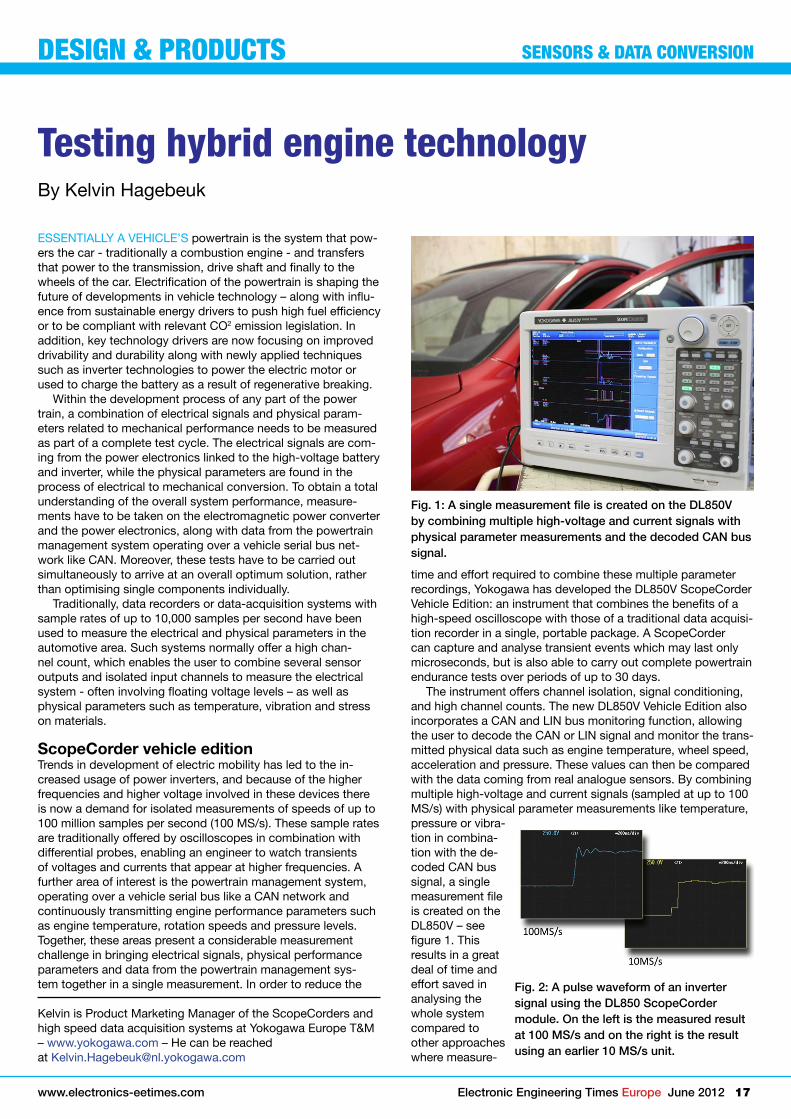
Fig. 1: A single measurement file is created on the DL850V by combining multiple high-voltage and current signals with physical parameter measurements and the decoded CAN bus signal.
Fig. 2: A pulse waveform of an inverter signal using the DL850 ScopeCorder module. On the left is the measured result at 100 MS/s and on the right is the result using an earlier 10 MS/s unit.
Kelvin is Product Marketing Manager of the scopecorders and high speed data acquisition systems at yokogawa Europe t&M – www.yokogawa.com – He can be reached at [email protected]

18 Electronic Engineering Times Europe June 2012 www.electronics-eetimes.com
ment files from multiple measurement instruments have to be combined before analyses can be done on a Pc.
Power electronics in automotive applicationsthe inverters used for automotive applications are increas-ingly incorporating faster, higher-voltage devices which re-quire isolated high withstand voltage measurements at higher sampling rates, as well as the ability to simultaneously measure greater numbers of signals for longer periods of time. traditional waveform measuring devices like digital storage oscilloscopes have limited capability for high-voltage inverter measurements because they lack the separately isolated inputs together with high-voltage isolation and high 12- or 16-bit resolution. Other waveform measuring solutions often require external (active) signal conditioning to achieve high-voltage isolation.
the Dl850 scopecorder, on the other hand, uses a technol-ogy known as isoPRO in its high-voltage measuring module to provide 100 Ms/s sampling with 1 kv isolation and 12-bit resolution with no need for external active signal conditioning devices. isoPRO technology employs a system whereby digital data is converted to optical signals using a semiconductor laser diode, with the data then being transferred via optical fibre to the instrument. as the data transfer rate of the semiconduc-tor laser diode is extremely high, large amounts of data can be transferred on a single device, and as a result the area of isolation becomes very small. Also, because optical fibre itself is an insulator, and the distance of signal transfer along the optical fibre is sufficient to provide the appropriate insulation, an insulating distance between the signal input and the main unit is provided even at a high voltage of 1kv. Using isoPRO technol-ogy, it becomes possible to package two channels of 100 Ms/s, 1 kv high withstand voltage isolation measurement circuits in a compact module measuring approximately 100 × 200 mm.
A further benefit of this technique is that it provides excel-lent noise rejection. Because the high voltage of inverters is switched at high speed, noise is necessarily introduced along the path of measurement. in the high-voltage isolation module, however, excellent noise rejection performance results in good cMMR (common-mode rejection ratio) values and also means that the floating voltage switching waveforms which are typical for inverters and devices such as iGBts can be captured with high precision – see figure 2.
Mechanical/physical valuesan engine test stand is a facility used to develop, characterise and test engines and simulate the powertrain. a sophisticated engine test stand houses several sensors (or transducers), data acquisition features and actuators to control the engine state. the Dl850 scopecorder has a modular structure and a wide range of input modules to monitor the mechanical perfor-
mance in combina-tion with electrical signals. trans-ducers convert signals from the engine into a form that the input
module can understand – normally a voltage signal. For ex-ample, engine speed is measured in revolutions per minute by a tachometer. this produces either a voltage output, or a pulse output which can be applied to the scopecorder to handle the pulse output and show the actual acceleration graph on the display - even to the extent of plotting the mechanical/electrical phase difference – see figure 3.
By using a temperature module, thermocouples (often K-type devices) can be used. these are robust and cheap, and are sufficiently accurate for the task. Up to 16 thermocouples per input module can be connected to the instrument. to monitor vibration in parts of the powertrain, an acceleration module with a piezoelectric sensor can be used.
Vehicle serial busthe can or lin network in a vehicle connects to the EcUs (electronic control units), and over this bus multiple parameters and control signals like temperature, wheel speed, acceleration and pressures are transmitted. together, the vehicle serial bus and the EcU units make up the powertrain management sys-tem. this means that, during the development process, not only electrical and mechanical signals coming from analogue sen-sors are measured, but also those physical parameters that are transmitted over the vehicle’s serial bus for referencing to the electrical and analogue sensor output parameters. the Dl850v vehicle Edition is able to decode these can and lin bus messages and display them as analogue values on the screen combined with the electrical or mechanical signals. an example of this is found in figure 4. This functionality makes it possible to directly map the relationship between data transmitted data over the vehicle serial bus with the electrical and mechanical values, providing real-time insight into the behaviour of the sys-tem. The DL850V supports CAN-dbc files (as developed by the Vector Group) and LIN network definition files, which allow the user to easily select the can and lin messages of interest.
ConclusionThe DL850V ScopeCorder offers all the measurement and analysis tools of a modern digital oscilloscope, including cursors, waveform parameter calculations, mathematics and DsP channels, and fast Fourier transforms. it also operates as a multi-channel data-acquisition unit/recorder, combining electrical, mechanical and vehicle serial bus measurements in one single unit. in most cases, users will be able to analyse data immediately and get results with no need for offline post-processing. this combination of features makes it the ideal tool for developments related to electrification of the powertrain and testing hybrid engine technology.
Fig. 3: A rotary encoder signal used to calculate the rotary angle trend.
Fig. 4: The DL850V Vehicle Edition is able to decode these CAN and LIN bus messages and display them as analogue values on the screen combined with the electrical or mechanical signals.
DESIGN & PRODUCTS SENSORS & DATA CONVERSION