testing web applications by modeling with fsmsweb.cs.du.edu/~sazghand/background_chap_papers/testing...
TRANSCRIPT

Testing Web Applications by Modeling with FSMs
Anneliese A. Andrews Jeff Offutt Roger T. AlexanderSchool of EE and CS Info and Software Engng Computer Science
Washington State University George Mason University Colorado State UniversityPullman, WA 99164 Fairfax, VA 22030 USA Fort Collins, CO 80523
[email protected] [email protected] [email protected] 703-993-1654 970-491-7026
Abstract. Researchers and practitioners are still trying to find effective ways to model and test Webapplications. This paper proposes a system-level testing technique that combines test generation basedon finite state machines with constraints. We use a hierarchical approach to model potentially large Webapplications. The approach builds hierarchies of Finite State Machines (FSMs) that model subsystems ofthe Web applications, and then generates test requirements as subsequences of states in the FSMs. Thesesubsequences are then combined and refined to form complete executable tests. The constraints are usedto select a reduced set of inputs with the goal of reducing the state space explosion otherwise inherent inusing FSMs. The paper illustrates the technique with a running example of a Web-based course studentinformation system and introduces a prototype implementation to support the technique.
Keywords: Testing of Web applications - System testing - Finite state machines
1 Introduction
Web applications currently make up one of the largest growth areas in software. Web applications do notjust give us new types of applications, but provide an entirely new way to deploy software applications toend users. Web applications employ a number of new languages, technologies, and programming models,and are used to implement highly interactive applications that have very high quality requirements. ModernWeb applications are sophisticated, interactive programs with complex GUIs and numerous back-end soft-ware components that are integrated in novel and interesting ways. Analyzing, modeling and testing theseapplications present a number of new challenges to software developers and researchers.
Web applications are much more complicated than simple HTML Web pages, and consist of more thanjust the front-end graphical user interfaces that users see. Instead, HTML is used to build GUIs as front-ends to arbitrarily complicated back-end software applications. Nielsen [23] claimed that in 1995, Webapplications were almost 100% interfaces (HTML), almost 90% interfaces in 1998, but by 2000 only about50% of Web applications were the interface. The back-end software has been growing in size and complexityin relation to the user interfaces, and is continuing to do so.
One technological challenge is that Web software applications are inherently heterogeneous in nature.Software components run on diverse hardware and software platforms, are written in diverse languages, arebased on diverse programming models, and combine new components, old components, and third party-produced Components Off The Shelf (COTS). A single Web application can be built with componentswritten in many different languages, including procedural, OO, interpreted, and hybrid languages like JSP.The user’s side includes browsers, embedded scripting languages, and applets; the server side includes HTML,CGI, Java Server Pages (JSPs), Java Servlets, and .NET technologies. They all interact with various softwarecomponents, middleware, and database servers. These other components may be on the server, the client,
1

or other computers “behind” the server. This heterogeneity introduces complexities in the integration thatare difficult to model and evaluate.
The heterogeneous nature of the software and the distributed deployment introduces complexities in thesoftware that must be handled during testing. At a more profound level, Web applications have the abilityto produce different GUIs “on demand” in response to user inputs, user state, and server state. TraditionalGUI applications have entirely static GUIs, and traditional GUI testing strategies do not address some ofthe dynamic complexities that our techniques try to address.
The heterogeneous nature of Web applications also influences the way software components are coupled.The term software coupling has been in use since at least the 1970s, with general acceptance that “less”coupling is better. Wu, Offutt and Du [33] defined Web software coupling as follows. The term methodgenerically refers to methods, procedures, subprograms and functions. A program exhibits tight coupling ifdependencies among the methods are encoded in the logic of the methods. That is, if A calls B, a change inA might require the logical structure of B to be changed. A program exhibits loose coupling if dependenciesamong the methods are encoded in the structure and flows of data among the methods, including definitionsin the callers and uses in the callees. So, for example, if A calls B, a change in A might result in the structureof the data changing, which in turn requires changes in the way B uses data items that are defined in A.This is the kind of coupling normally seen when data abstraction and information hiding is employed.
A program exhibits extremely loose coupling (ELC) if dependencies among the methods are encodedentirely in the contents of the data being transmitted, not in the structure. If A sends data to B, a changein A might change the contents of the data that B uses, but not the structure of the data.
The N-tier structure of most Web applications encourage ELC, and the heterogeneous nature of thesoftware makes ELC crucial to the success of the applications. Developers often have no contact other thanan agreement or understanding of the input or output specifications of the other component (for example,through an API). Components are modified, inserted, and replaced without full understanding of connectedcomponents. Software components can now even be reconfigured dynamically as new Web services appear orother components are taken offline. This extremely loose and dynamic coupling provides powerful abstractionabilities to the developers, but makes the analysis required for testing extremely difficult.
1.1 Problems in Testing Web Applications
This paper defines a Web page to be information that can be viewed in a single browser window. A Webpage may be stored as a static HTML file, or it may be dynamically generated by software such as a JSP ora Java Servlet. A Web site is a collection of Web pages and associated software components that are relatedsemantically by content and syntactically through links and other control mechanisms. Web sites can bedynamic and interactive. A Web application is a program that runs in whole or in part on one or moreWeb servers and that can be run by users through a Web site.
The literature on testing Web applications is still scarce and there is no widespread agreement on howto categorize the technical problems. An important factor influencing Web applications is how the differentpieces are connected. We make our initial attempts to categorize testing in terms of the following connections.
1. Static links (HTML → HTML): Most of the early literature on Web testing focused on link validation.Note that this does not address any software or dynamic issues.
2. Dynamic links (HTML → software): HTML forms send data to software components that process thedata. One issue with testing dynamic links is that data must be found or created for the forms.
3. Dynamically created HTML (software → HTML): Web software typically responds to the user withHTML documents. The contents of the HTML documents often depend on inputs, which complicatestesting.
4. User/time specific GUIs (software + state → HTML): HTML documents whose contents and form aredetermined by not just inputs, but some state of the server, such as the data or time, the user, orsession information.
2

5. Operational transitions (user): Transitions that the user introduces into the system outside of thecontrol of the HTML or software. Operational transitions include use of the back button, the forwardbutton, and URL rewriting.
6. Software connections: This includes connections among back-end software components, such as methodcalls and forwarding among Web components.
7. Off-site software connections: Some Web applications will access software components that are availableat a remote site. This type of connection, while powerful, is difficult to test because little is knownabout the off-site software.
8. Dynamic connections: Both the J2EE platform and .NET allow new Web components to be installeddynamically during execution, and the Web application can detect and use the new components. J2EEuses Java reflection and Javabeans to accomplish this. This type of connection is especially difficultto test because the tester does not know how the components will behave before deployment andexecution.
This paper addresses the problem of black box system or application testing of Web applications. Ourapproach applies test criteria to a structured model of the application. Tests for entire Web applicationsare created by composing sub-tests derived from models of lower level abstractions of the applications. Theprimary focus is on the state dependent behavior of Web applications.
Finite state machines (FSM) provide a convenient way to model software behavior in a way that avoidsissues associated with the implementation. Several methods for deriving tests from FSMs have also beenproposed [5, 8, 25]. Theoretically, Web applications can be completely modeled with FSMs, however, evensimple Web pages can suffer from the state space explosion problem. There can be a large variety of possibleinputs to text fields, a large number of options on some Web pages, and choices as to the order in whichinformation can be entered. Factors such as these mean that a finite state machine can become prohibitivelylarge, even for a single page. Thus, an FSM-based testing method can only be used if techniques are found togenerate FSMs that are descriptive enough to yield effective tests yet small enough to be practically useful.
The technique in this paper, FSMWeb, addresses the state explosion problem with a hierarchical collectionof aggregated FSMs. The bottom level FSMs are formed from Web pages and parts of Web pages calledlogical Web pages, and the top level FSM represents the entire Web application. Application level testsare formed by combining test sequences from lower-level FSMs. To allow the combined test sequences tobe meaningful, constraints on parameter values that are propagated from earlier parts of the sequence areexpressed.
This research does not, as yet, address all the dynamic aspects of Web applications. From the problemlist above, the research in this paper addresses items 1, 2, 3, 4 and 6, has the potential to address item5 if the tester chooses, and does not address the last two. Items 1, 2, 3, and 6 are addressed directly byour FSM model. Item number 4, user/time specific GUIs, is addressed by basing the lowest level FSMs on“logical” instead of complete Web pages. Item number 5, operational transitions, can be addressed if thetester chooses to explicitly model those transitions. However, this is expensive within an FSM model andthus this technique may not be appropriate for addressing operational transitions.
Section 2 introduces a small example Web application that is used to illustrate our concepts. Our hybridapproach for generating tests for Web applications consists of two phases. The first phase, described inSection 3, builds a representation of the application to be tested that is suitable for test generation purposes.The second phase, described in Section 4, generates tests from this representation. Test generation itself hasseveral stages. It starts with generating sequences of actions. Actions are also labeled with parameters andspecific constraints on parameters. Parameter values are resolved in the second step, subject to test coveragecriteria for parameter values and applicable constraints. Section 5 describes an architecture for a tool setthat supports this approach and describes choices for automation. It also describes the automation approachfor our research prototype. Section 6 describes other research that is related to Web software testing andtesting based on FSMs and Section 7 offers concluding remarks.
3

2 An Example Web Application: CSIS
This research addresses the testing of Web applications from an external view. The Web provides a newmechanism to deploy software and there are a number of differences between Web application deploymentand traditional deployment methods (including bundling with operating systems, “shrink-wrap” software,and contract software). Web applications are deployed across a network and they can exhibit unusualflows of control. The structure of the software design is usually different from traditional software, thesoftware components are integrated in different ways, the components communicate in unusual ways, andWeb applications use new software technologies such as session management. This research addresses externaltesting issues related to the unique user-level deployment and software design structure.
We have developed a small Web-based application to illustrate the FSMWeb technique. The CourseStudent Information System (CSIS) helps manage data associated with a college class by offering views forthe professor, a teaching assistant (TA), and the students. CSIS supports several services for each user. Usersfirst go through a login screen, where they enter a password that identifies them as a student, professor, orTA. They can then enter a PIN to see personal data. The services that CSIS provides are listed in Table 1.
Table 1: CSIS Services.
Student Professor Teaching Assistant (TA)Information form View student information Post gradesView grades Post grades Email classEmail TA Email class Email studentEmail professor Email student Email professorSubmit homework Email TA Download homeworkView course information Download homework View Course information
Post course information
After students log in, a Java Servlet generates a blank form. They can fill out the form and submit thedata to be stored in an XML file, or they can enter their name and PIN to retrieve their old information.They can then update and save that information. Each screen has a toolbar of link-buttons to access theother services, including Information (I), Grades (G), Email TA (ETA), Email Professor (EP), Homework (H),and Course information (C).
The professor can retrieve information on all students in a tabular format, get a list of email addressesformatted for creating a mail alias, or an HTML file with links to each student’s class Web page. Theprofessor’s services are primarily provided by Servlets and Java Server Pages that work through a Java Beanto retrieve the data from an XML file.
This example, although small, includes several of the challenging elements that are typical of Web ap-plication software. Several different types of software (HTML, JavaScript, Java Servlet, Java Beans, JSPs)communicate in a very loose and flexible way. A small problem in the JavaScript on one HTML page can,through the way the data is transmitted, have unforeseen affects on a seemingly unrelated JSP. This kindof coupling brings new challenges in building models of Web applications for testing purposes. The CSISexample is used to illustrate the FSMWeb method in Sections 3 and 4.
As a first step in analyzing the CSIS Web application, we express logical views of the application basedon users. Other views of the software are possible, and implications of this choice are discussed in Section7. Figure 1 shows some of the logical views for the student services. CSIS has two levels of access. Thepassword identifies a user’s role as student, professor or TA, and the PIN identifies a user’s identity. Thus,the password provides access to one of the three logical views and the PIN provides access to data.
The Services box in Figure 1 represents the six student services from Table 1, and two services areelaborated, View grades and Info form. The Info Form allows the students to Retrieve their existingdata (RT), Reset the form (RS), Submit New data (SN), and Submit an Update (SU). If the student wants
4

to retrieve existing data, a last name and a PIN must be entered. The View Grades service also asks thestudents to enter a last name and a PIN. If valid, the grades are shown. The boxes in Figure 1 are roughapproximations of screens, with the six buttons on the bottom of View grades and Info form providingshortcut links for the Services menu.
Entry Portal
Password
Submit
Services
Info FormView gradesEmail TAEmail ProfSubmit homeworkView course information
Info Form
Logical web pages
Reset button (RS)
LNameFNameMajorOtherURLEMailPhone
Submit Update (SU)
Submit
Retrieve (RT)
LNamePIN Submit
Submit New (SN)
LNameFNameMajorOtherURLEMailPhone Submit
CHEPETAGI
Professor view
TA view
Student view
View Grades
LName
Submit
PIN
Grades
__________
_____
CHEPETAGI
Figure 1: Student Information System Logical View.
3 Modeling Web Applications
Our approach to testing Web applications proceeds in two phases. Phase 1 builds a model of the Webapplication. This is done in four steps: (1) the Web application is partitioned into clusters, (2) logical Webpages are defined, (3) FSMs are built for each cluster, and (4) an Application FSM is built to represent theentire Web application. Phase 2 then generates tests from the model defined in Phase 1; test generation isdescribed in Section 4.
5

3.1 Partitioning into Clusters and Logical Web Pages
A common problem with deriving tests from finite state machines is that the complexity of the softwarecan result in a state space explosion. Also, the typical heavy user interaction of Web applications results inlarge numbers of user choices, each of which can be modeled as a transition in the FSM. With client-sideprogramming such as JavaScripts, the number of user choices is further increased. Thus, if FSMs are to beused to model UI-intensive software in general, and Web applications in particular, it is necessary to avoidor manage the state space explosion problem. This research avoids the state space explosion problem bysuccessively partitioning Web applications into clusters, each of which is composed of Web pages and otherclusters.
As with any hierarchical decomposition, the tester must consider different types of information at differentlevels of abstraction. It is possible that design documentation will already exist that can be used to supportthis activity, but for now we assume the decomposition is the tester’s job and leave the use of pre-existingdocumentation to future research. It may also be possible to define rules that are strict enough to allowclusters to be identified automatically; this topic is also left as future research. Depending on the size andcomplexity of the Web application, the number of decomposition levels may be large or small.
We use the general term cluster to refer to collections of software modules and Web pages that implementsome logical function. The first step in decomposition will be to partition the Web application into clusters.At the highest level, clusters should be abstractions that implement functions that can be identified by users.At lower levels, clusters should be cohesive software modules and Web pages that collectively work togetherto implement a portion of a user level function. At the bottom level, clusters may be individual Web pagesand software modules that represent single major functions themselves. Clusters can be identified from thesite navigation layout, coupling relationships among the components, and design information.
It should be obvious that this process is not only subjective, but can have a major impact on thequality of the resulting tests. This is both an opportunity and a problem; an opportunity for experienced,well educated test engineers to have a positive impact on the software, and a problem leading to lack ofrepeatability and weak testing if the decomposition is done poorly. We hope to experimentally evaluate howmuch of a difference this makes, and in the future explore techniques to reduce the amount of subjectivity.
This process is illustrated with CSIS. At the design level, CSIS has three subsystem clusters, one for eachtype of user (students, teachers, and teaching assistants). The lower level clusters within each subsystemcluster can be grouped around the services in Table 1. The student services can be further partitioned bytype of service (Info Form versus View Grades).
Many Web pages contain more than one HTML form, each of which can be connected to a differentback-end software module. To facilitate testing of these modules, Web pages are modeled as multiple LogicalWeb Pages (LWP). An LWP is either an entire physical Web page or the portion of a Web page that acceptsdata from the user through an HTML form and then sends the data to a specific software module. LWPscan be automatically extracted because each separate form on a Web page is defined by an HTML Form tag.The back-end software that processes the form data is declared in the Form Action attribute, and client-sidesoftware (such as JavaScripts) are referred to in individual Form input fields.
Modeling LWPs allows problem number 4 in Section 1.1, user/time specific GUIs, to be addressed.Although a Web page may vary in structure when dynamically created in response to state, the individualLWPs will not vary in structure. The only changes will be in which LWPs and in what order they appearto the user. Thus, this part of the FSM will remain constant even when HTML is created dynamically.
As an example, a Web page may have a form that accepts a user name and a password for logging in.This would constitute a logical Web page. We characterize an LWP by the set of inputs that lead to anaction on the part of the Web application. The inputs include the data fields, selection buttons, radio boxes,and submit buttons (in the case of server-side execution) or user events (in the case of client-side scripting).Thus LWPs are described in terms of sets of related inputs and actions. At this time, LWPs are identifiedby hand but it will be relatively simple to extract LWPs by parsing the HTML.
After a Web application A has been partitioned into clusters, the next step is to derive a Finite StateMachine (FSM) for each cluster. First, FSMs are generated from the bottom-level clusters that only contain
6
software modules and Web pages (that is, no clusters). Next, aggregate FSMs are constructed for high-levelclusters, in which each FSM from constituent clusters is represented by a single node (state). Ultimately, anApplication Finite State Machine (AFSM) will define a finite state model of the entire Web application.
To simplify test generation, each FSM is assumed to have only one initial and one final node. If a linkor other navigation is found from a Web page wi in a cluster Ca to a Web page or software module wj inanother cluster Cb, then an edge is added from the node that represents Ca in the aggregate FSM, na, to thenode that represent Cb, nb. Later in the analysis (in Subsection 3.3), we annotate edges with informationthat propagates across clusters.
If an FSM has multiple entry or exit points, “dummy” initial or final nodes are added to ensure thesingle-entry, single-exit property. Thus, the edge in the aggregate graph from na to nb is technically fromthe final node in Ca to the initial node in Cb. This has ramifications for test composition, which are discussedin Section 4. (Most importantly, no input is needed to traverse edges into the dummy final nodes or edgesout of the dummy initial nodes.)
The final result of this partitioning will be a collection of autonomous (separate but interacting) finitestate machines with the following two properties. First, they are small enough to efficiently allow testsequences to be generated. Second, they clearly define the information that propagates among the FSMs.This partitioning allows the partial test sequences to be aggregated into an overall test sequence.
3.2 Partitioning CSIS
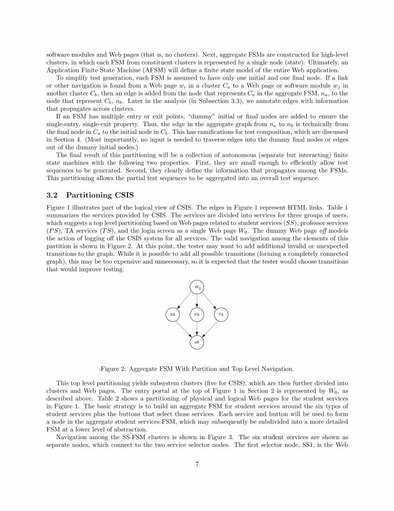
Figure 1 illustrates part of the logical view of CSIS. The edges in Figure 1 represent HTML links. Table 1summarizes the services provided by CSIS. The services are divided into services for three groups of users,which suggests a top level partitioning based on Web pages related to student services (SS), professor services(PS), TA services (TS), and the login screen as a single Web page W0. The dummy Web page off modelsthe action of logging off the CSIS system for all services. The valid navigation among the elements of thispartition is shown in Figure 2. At this point, the tester may want to add additional invalid or unexpectedtransitions to the graph. While it is possible to add all possible transitions (forming a completely connectedgraph), this may be too expensive and unnecessary, so it is expected that the tester would choose transitionsthat would improve testing.
W
SS
off
PS TS
0
Figure 2: Aggregate FSM With Partition and Top Level Navigation.
This top level partitioning yields subsystem clusters (five for CSIS), which are then further divided intoclusters and Web pages. The entry portal at the top of Figure 1 in Section 2 is represented by W0, asdescribed above. Table 2 shows a partitioning of physical and logical Web pages for the student servicesin Figure 1. The basic strategy is to build an aggregate FSM for student services around the six types ofstudent services plus the buttons that select those services. Each service and button will be used to forma node in the aggregate student services FSM, which may subsequently be subdivided into a more detailedFSM at a lower level of abstraction.
Navigation among the SS-FSM clusters is shown in Figure 3. The six student services are shown asseparate nodes, which connect to the two service selector nodes. The first selector node, SS1, is the Web
7

Table 2: Clusters and Nodes For SS-FSM.
Node Cluster ExplanationSS1 Select Service 1 Menu of named servicesSS2 Select Service 2 List of navigation buttons for services at the bottom of
student service pagesI Info Form Physical Info Form page without service navigation but-
tons at bottomG Grades View Grades and Grades pagesETA Email TA Pages related to sending email to TAEP Email Prof Pages related to sending email to professorH Submit homework Pages related to sending homeworkC View course info Pages related to course materials
page for service selection in Figure 1, and the second, SS2, is the set of service selection buttons at thebottom of each page that allows student services to be activated (there are two pages in Figure 1 of thistype). The edges show possible navigation among the services.
SS1
G
SS2
CHEPETAI
Figure 3: Cluster and Navigation for Student Services.
As an example of building the lowest level FSMs, we show how to construct the FSM for the Info Formservice I and the View Grades service G. Table 3 shows the nodes and logical Web pages related to (I).These appeared in Figure 1 as the square boxes Retrieve (RT ), Reset button (RS), Submit New (SN), andSubmit Update (SU). This service can be entered from either of the two Select Service facilities (the Servicespage (SS1) or the Service navigation buttons (SS2)).
Table 3: Nodes for Info Form-FSM.
Node LWP Explanationfrom SS1/2 From Select Service 1/2 Connection from either service selection facilityto SS2 To Select Service 2 Connection to list of navigation buttons for services at the
bottom of student service pagesRT Retrieve Retrieve student infoRS Reset Reset student info data in databaseSN Submit New Submit new student infoSU Submit Update Submit updated information
Figure 4 shows the navigation among the logical Web pages that represent the Info Form service. The
8

navigation is based on the following design decisions for the underlying CSIS:
• Reset cannot be the first action.
• The student cannot leave this service as the first action after a reset; the student must enter informationfirst.
• The student cannot leave this services as the first action after a retrieve; the student must performsome other action before leaving (for example, submit an update).
Obviously, other choices for which navigation is allowable could be defined, but this initial set is used toillustrate the testing technique.
SS1/2
RS
SS2
SUSN
RT
Figure 4: Logical Web Pages and Navigation for Info Form Cluster.
We define logical Web pages and navigation among them for the View Grades cluster in a similar way.View Grades consists of two logical Web pages, the physical Web page View Grades in Figure 1 and thephysical Web page Grades. In addition, connections to and from student services selectors are added, justlike in the prior FSM for Information services. Table 4 summarizes these nodes and corresponding logicalWeb pages. Figure 5 shows navigation among the nodes.
Table 4: Nodes for View Grades-FSM.
node LWP Explanationfrom SS1/2 From Select Service 1/2 Connection from either service selection facilityto SS2 To Select Service 2 Connection to list of navigation buttons for services at the
bottom of student service pagesV View Grades Authentication for viewing gradesG Grades Grade display
fromSS1/2
toSS2
GV
Figure 5: Logical Web Pages and Navigation for View Grades Cluster.
9
3.3 Annotating FSMs and Logical Web Pages
The partitioning of the logical Web pages results in a hierarchical collection of finite state machines. At thelowest level, logical Web pages are represented by nodes in FSMs that model behavior of software modulesand Web pages. Edges represent transitions among logical Web pages and software modules. Each clusterin turn forms a node in a higher level FSM that models behavior of clusters. Edges in both levels of FSMsare annotated with inputs and constraints that may be associated with the transition.
3.3.1 Input Selection Constraints for Logical Web Pages
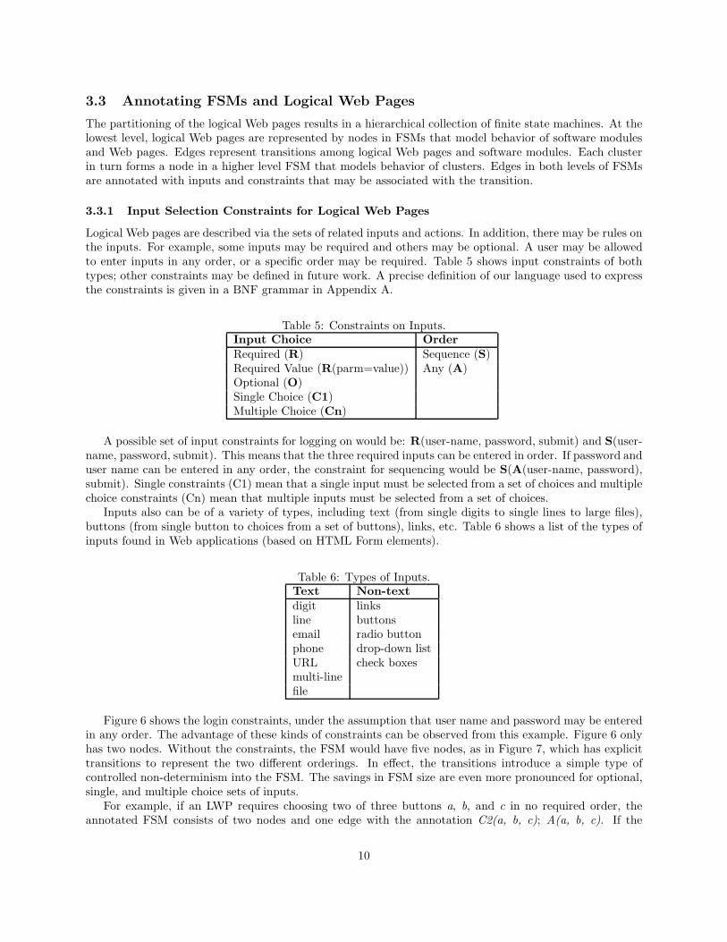
Logical Web pages are described via the sets of related inputs and actions. In addition, there may be rules onthe inputs. For example, some inputs may be required and others may be optional. A user may be allowedto enter inputs in any order, or a specific order may be required. Table 5 shows input constraints of bothtypes; other constraints may be defined in future work. A precise definition of our language used to expressthe constraints is given in a BNF grammar in Appendix A.
Table 5: Constraints on Inputs.Input Choice OrderRequired (R) Sequence (S)Required Value (R(parm=value)) Any (A)Optional (O)Single Choice (C1)Multiple Choice (Cn)
A possible set of input constraints for logging on would be: R(user-name, password, submit) and S(user-name, password, submit). This means that the three required inputs can be entered in order. If password anduser name can be entered in any order, the constraint for sequencing would be S(A(user-name, password),submit). Single constraints (C1) mean that a single input must be selected from a set of choices and multiplechoice constraints (Cn) mean that multiple inputs must be selected from a set of choices.
Inputs also can be of a variety of types, including text (from single digits to single lines to large files),buttons (from single button to choices from a set of buttons), links, etc. Table 6 shows a list of the types ofinputs found in Web applications (based on HTML Form elements).
Table 6: Types of Inputs.Text Non-textdigit linksline buttonsemail radio buttonphone drop-down listURL check boxesmulti-linefile
Figure 6 shows the login constraints, under the assumption that user name and password may be enteredin any order. The advantage of these kinds of constraints can be observed from this example. Figure 6 onlyhas two nodes. Without the constraints, the FSM would have five nodes, as in Figure 7, which has explicittransitions to represent the two different orderings. In effect, the transitions introduce a simple type ofcontrolled non-determinism into the FSM. The savings in FSM size are even more pronounced for optional,single, and multiple choice sets of inputs.
For example, if an LWP requires choosing two of three buttons a, b, and c in no required order, theannotated FSM consists of two nodes and one edge with the annotation C2(a, b, c); A(a, b, c). If the
10

corresponding FSM with single inputs is used, then we can have the inputs a followed by b or c, b followedby a or c, or c followed by a or b. This FSM would have 10 nodes and 9 edges as shown in Figure 8.Similarly, having three required inputs R(a, b, c), again without any required order, results in an FSM withtwo nodes and one edge, while the corresponding FSM with single inputs would require 16 nodes with 15edges. In addition to allowing FSMs to be smaller, generating input values based on these constraints issimpler, more straightforward, and more flexible with respect to changing test objectives than with a largerFSM representation.
21R (user-name, password, submit)
S (A (user-name, password), submit)
Figure 6: Annotated FSM for Login.
21
user-nam e
password
password submituser-name4 5
3
Figure 7: FSM for Login Without Constraint Annotation.
2
1
a
4
7
3
8
5
6
9
10
b
c
a
a
b
b
c
c
Figure 8: FSM for Three Button UI With no Constraint Annotation.
Each cluster identified during partitioning is supplied to a tool that creates an annotated FSM. Weassume that the clusters are small enough so that it is possible to efficiently generate test sequences fromthe FSM automatically.
3.3.2 FSM Info Form and View Grades
Table 7 shows all annotations on the FSM transitions for the student information form of Figure 4. TheFSM transition constraints for the View Grades service of Figure 5 are shown in Table 8. In the transitionannotation tables, the leftmost column identifies transitions by their pre- and post-nodes. The second column
11

identifies the constraints, the third encodes each set of constraints in an input alphabet (Σ), and the fourthcolumn (Ω) lists the post-node, or output. The post-nodes are used to provide a partial test oracle for thetest input.
The first row is a transition from SS1 (the Select Service 1 cluster) to SN (the Submit New cluster).The input alphabet codes are assigned arbitrarily as a matter of convenience: as a reference for the fullconstraint in the constraint columns (column 2). The outputs are the target states of the transitions.
Table 7: Annotations for Info Form FSM Transitions.
Transition Constraints Σ Ω(SS1/2, SN) R (Lname, Fname, major, other, URL, email, phone, buttonSN) a SN
S (A (Lname, Fname, major, other, URL, email, phone), buttonSN)(SS1/2, RT) R (Lname, PIN, buttonRT) b RT
S (A (Lname, PIN), buttonRT)(SS1/2, SU) R (Lname, Fname, major, other, URL, email, phone, buttonSU) c SU
S (A (Lname, Fname, major, other, URL, email, phone), buttonSU)(RT, RS) R (buttonRS) d RS(RS, RT) R (Lname, PIN, buttonRT) b RT
S (A (Lname, PIN), buttonRT)(RT, SU) R (Lname, Fname, major, other, URL, email, phone, buttonSU) c SU
S (A (Lname, Fname, major, other, URL, email, phone), buttonSU)(RS, SU) R (Lname, Fname, major, other, URL, email, phone, buttonSU) c SU
S (A (Lname, Fname, major, other, URL, email, phone), buttonSU)(RS, SN) R (Lname, Fname, major, other, URL, email, phone, buttonSN) a SN
S (A (Lname, Fname, major, other, URL, email, phone), buttonSN)(SN, SS2) none e SS2(SU, SS2) none e SS2
Table 8: Annotations for View Grade FSM Transitions.
Transition Constraints Σ Ω(SS1, V) none e V(V, G) R (Lname, PIN, buttonV) f G
S (A (Lname, PIN), buttonV)(G, SS2) none e SS2
3.4 Propagating Inputs Among FSMs
Aggregate FSMs (AFSMs) combine FSMs from lower levels of abstractions. Thus a node in an AFSMrepresents either (1) an entire FSM at the next lower level in the hierarchy, or (2) a logical web page.Arcs represent possible transitions between lower level FSMs and logical web pages. Annotations on thetransitions represent input constraints and information that needs to propagate between lower level FSMs.Two types of information can be propagated:
1. Continue-use input values: Inputs for which values have been selected and must continue to be used inthe successor FSM. For example, a username and password that is entered in one cluster must be passed tothe next cluster and the same values must be used. If continue-use inputs have constraints, they must also
12

propagate. If these relationships are defined implicitly in a database, they will be obtained automatically,else they will be derived from semantic descriptions of the software.
2. Single-use inputs: Inputs for which values may have been selected but for which the same values cannotbe selected again. Single-use inputs represent selection without replacement. For example after a student’sdata that was deleted from the class data base in one part of the application (for example, the Admin FSM),the student’s name cannot be used in a subsequent FSM to assign grades. Another example is if studentsmay select which paper to present in class from a set, each paper may be selected at most once. If a valueis marked as single-use once, it cannot be used again during the same test.
Turning to the CSIS example, assume that the login function is in the first cluster. Edges to follow-onclusters should be annotated with “user-name” as a continue-use input. Thus, the functions and inputs areconstrained by the services it provides to this particular user. If a node in an aggregate FSM is also a logicalweb page, we also need to annotate the edge with input constraints applicable to the inputs of the logicalweb page.
3.5 Aggregate FSMs for CSIS
Table 9 lists the input selection constraints and the propagation rules for the Student Services aggregateFSM of Figure 3. The menu in SS1 has the same functionality as the button-menu in SS2, and the menuentries in SS1 correspond to the buttons in SS2. For convenience, Table 9 uses the shortened version fromSS2 (for example “Info Form” in SS1 is “I” in SS2). The columns Σ and Ω in Table 9 represent the inputsand outputs of the lower level FSMs. As before, Σ is the input alphabet and Ω is the output alphabet.
To turn the top level navigation diagram into an Application FSM, we need to define the constraints oninputs and the propagation rules among its nodes. The top level AFSM of Figure 2 represents the loginprocedure and an automatic transfer to the correct services for each type of user. Three classes of users areidentified by three types of passwords: professor password (PPWD), student password (SPWD), and TApassword (TPWD). The user enters a password and presses a submit button. For each transition in Figure2, Table 10 shows the corresponding inputs and input constraint rules, their encoding as an input alphabet(for abbreviation), and the corresponding output state. Table 10 also lists the propagation rules for valuegeneration. The only transitions with value propagation rules are transitions from login to the services. Nopropagation rules are needed for sign-off. Even for the login propagation rules, they will only be needed ifthe password is needed later.
4 An Approach to Testing Web Applications
The annotated FSMs and aggregate FSMs are used to generate tests. We first focus on generating testsas sequences of transitions, and consider values for inputs separately. A test sequence is a sequence oftransitions in an FSM and the associated constraints. Assume FSM f has test sequences Sf1, Sf2, ... SfN .Furthermore, suppose FSM f appears in an aggregate FSM as node f , and there is an edge in the FSM fromnode f to node g with annotation A.
Partial aggregate test sequences are generated as follows. Each test sequence from FSM f is attached toeach test sequence from FSM g, with annotation A in the middle. Formally, if test sequence j from FSM fis Sfj , and test sequence k from FSM g is Sgj , then a partial aggregate test sequence is Sfj ; A; Sgk. Fullaggregate test sequences are created by combining partial aggregate sequences. Assume the aggregate FSMhas a test sequence of nodes f1, f2, ..., fn, with annotations A12 A23, ..., An−1n and the FSMs from thenodes in the aggregate FSM test sequence have test sequences Sf1,j , Sf2,j , ..., Sfn,j . Then the aggregatetest sequence is Sf1,j ; A23; Sf2,j ; A23; ...; An−1n; Sfn,j.
Recall from Section 3.1 that we assume that all FSMs have single initial and single final nodes, andfurthermore that dummy nodes are sometimes added to FSMs to ensure this property. This technique fitsinto the scheme for generating partial aggregate test sequences quite elegantly. If FSM f has two “real” finalnodes fx and fy, then a dummy final node is added, fz, with incoming edges from fx and fy. Edges (fx, fz)
13

Table 9: Annotations for Student Services Aggregate FSM Transitions.
Transition Constraints Σ Ω(SS1, I) R(I) g I
continue-use (Lname, PIN)(SS1, G) R(G) h G(SS1, ETA) R(ETA) i ETA(SS1, EP) R(EP) j EP(SS1, H) R(H) k H(SS1, C) R(C) l C(I, SS2) continue-use (Lname, PIN) m SS2(SS2, I) R(I) n I
continue-use (Lname, PIN)(G, SS2) continue-use (Lname, PIN) m SS2(SS2, G) R(G) o G
continue-use (Lname, PIN)(ETA, SS2) continue-use (Lname, PIN) m SS2(SS2, ETA) R(ETA) p ETA
continue-use (Lname, PIN)(EP, SS2) continue-use (Lname, PIN) m SS2(SS2, EP) R(EP) q EP
continue-use (Lname, PIN)(H, SS2) continue-use (Lname, PIN) m SS2(SS2, H) R(H) r H
continue-use (Lname, PIN)(C, SS2) continue-use (Lname, PIN) m SS2(SS2, C) R(C) s C
continue-use (Lname, PIN)
Table 10: Annotations for Top Level AFSM Transitions.
Transition Constraints Σ Ω(W0, SS) R (pwd ∈ SPWD, submit) t SS
S (pwd, submit)continue-use (pwd)
(W0, PS) R (pwd ∈ PPWD, submit) u PSS (pwd, submit)continue-use (pwd)
(W0, TS) R (pwd ∈ TPWD, submit) v TSS (pwd, submit)continue-use (pwd)
(SS, off), (PS, off) R (logout) x off(TS, off)
and (fy, fz) have no annotation, but any test sequence for f that would naturally have ended with fx nowends with (fx, fz) and any test sequence that would have ended with fy now ends with (fy, fz).
14

Sequences of transitions for cluster and aggregate FSMs are generated by applying standard graph criteriasuch as all nodes or all edges [2, 5, 8, 25]. Because the graphs being used are FSMs, it is also important totest for invalid transitions. Test sequences that contain invalid transitions are not expected to reach finalnodes in the FSM, so this step is not applied until the final application test sequences are constructed.
A difficult question is then how many and which test sequences from the lower level FSMs should becombined to form the test sequences for the aggregate FSMs. If an aggregate FSM test sequence has n nodes,and each node fi represents an FSM that has Mi test sequences, then there can be up to M1 ∗M2 ∗ ... ∗Mn
aggregate test sequences, or O(Mn), where M is the average number of FSM test sequences.This exponential number will almost certainly be too many to use for testing in most cases, thus we
must choose FSM test sequences to combine. The combination strategies given in Chapter 3 of Ammannand Offutt [2] can be used. The each choice criterion [1, 2] requires that each FSM test sequence is used inat least one aggregate FSM test sequence. This results in M aggregate FSM test sequences, where M is themaximum number of FSM test sequences. The base choice criterion [1, 2] requires that the tester identifya key “base choice” from each collection of FSM test sequences. Then a base aggregate test sequencesis formed by combining all the base choice FSM test sequences. Subsequent aggregate test sequences areformed by holding all but one base choice test sequence constant and substituting all other test sequencesfor the non-constant test sequence. This results in M1 + M2 + ... + Mn − n + 1 aggregate test sequences,or O(M ∗ n), where M is the average number of FSM test sequences. The base choice could be the mostcommonly used sequence of actions, the shortest, or the longest. The base choice can be selected by thetester or automatically.
Whether to use the each choice or base choice criterion can be decided based on the tester’s assessmentof the cost and benefit tradeoff. Base choices are chosen by the tester according to experience and domainknowledge, or randomly if the tester decides it does not matter. Once base choices are identified, aggregatetest sequences are generated automatically.
4.1 Test Sequences for CSIS
For the running CSIS example, we apply transition coverage to the FSMs, generating test sequences tocover each transition. A test sequence is a sequence of FSM edges and their annotations (constraints). Testsequences for the Info Form and View Grades FSMs are shown in Tables 11 and 12. The first columnindicates which edges are covered, the second column indicates the constraint sequence (using the inputalphabet defined in the Σ columns in Tables 7 through 10). Thus, the first sequence in Table 11 for the InfoForm FSM covers edges (SS1/2,SN) and (SN, SS2) from Table 7 and the FSM in Figure 5, and uses the testsequence of constraints “ae”.
The test sequences for View Grades is shown in Table 12. Note that “e” is a null constraint (thecorresponding transition in the FSM has no constraint), so the constraints shown are all for the constraintlabeled “f.”
These sequences ultimately will be substituted into the aggregate sequences for the aggregate FSM. Forthe CSIS example, this is the FSM for Student Services. A transition cover for the Student Services FSM(Figure 3 and Table 9) is given as:
Transition Cover PSS1; g; I; m; SS2; n; I; m; SS2SS1; h; G; m; SS2; o; G; m; SS2SS1; i; ETA; m; SS2; p; ETA; m; SS2SS1; j; EP ; m; SS2; q; EP ; m; SS2SS1; k; H ; m; SS2; r; H ; m; SS2SS1; l; C; m; SS2; s; C; m; SS2
Note that this aggregation sequence includes not merely a sequence of inputs, but also the states. Thisidentifies generated output for a partial oracle, and also identifies the FSM to which the sequence belongs.
15

Table 11: Test Sequences for Info Form FSM.
Edge Sequence Constraint ConstraintSequence
(SS1/2, SN) ae R(Lname, Fname, major, other, URL, email, phone, buttonSN)(SN, SS2) S(A(Lname, Fname, major, other, URL, email, phone), buttonSN)(SS1/2, RT) bdae R(Lname, PIN, buttonRT)(RT, RS) S(A(Lname, PIN), buttonRT)(RS, SN) R(buttonRS)(SN, SS2) R(Lname, Fname, major, other, URL, email, phone, buttonSN)
S(A(Lname, Fname, major, other, URL, email, phone), buttonSN)(SS1/2, RT) bdbce R(Lname, PIN, buttonRT)(RT, RS) S(A(Lname, PIN), buttonRT)(RS, RT) R(buttonRS)(RT, SU) R(Lname, PIN, buttonRT)(SU, SS2) S(A(Lname, PIN), buttonRT)
R(Lname, Fname, major, other, URL, email, phone, buttonSU)S(A(Lname, Fname, major, other, URL, email, phone), buttonSU)
(SS1/2, RT) bdce R(Lname, PIN, buttonRT)(RT, RS) S(A(Lname, PIN), buttonRT)(RS, SU) R(buttonRS)(SU, SS2) R(Lname, Fname, major, other, URL, email, phone, buttonSU)
S(A(Lname, Fname, major, other, URL, email, phone), buttonSU)(SS1/2, SU) ce R(Lname, Fname, major, other, URL, email, phone, buttonSU)(SU, SS2) S(A(Lname, Fname, major, other, URL, email, phone), buttonSU)
Table 12: Test Sequences for View Grades FSM.
Edge Sequence Constraint ConstraintSequence
(SS1/2, V) efe R(Lname, PIN, buttonV)(V, G) S(A(Lname, PIN), buttonV)(G, SS2) C1(services)
The aggregation sequence is based on the input constraint abbreviations of Table 9. This means that eachinput needs to be replaced with the corresponding constraint in Table 9.
For each node in the student services aggregate sequence, the test sequences for the lower level FSMsmust be substituted. For example, node I appears twice in the first transition sequence for P. Node I iscovered by the five test sequences given in Table 11. If the each choice criterion defined in Section 4 is used,then each occurrence of I will be replaced by each of the five test sequences, resulting in five tests total. Ifthe base choice criterion is used, then assume the first test sequence “ae” is chosen as base. Then nine totalaggregate test sequences will be generated.
As a more detailed example, we will perform the substitution for the second path in P . This meanssubstituting test sequences in Table 12 for both occurrences of G. This results in the following path (usingthe abbreviations for the constraints and showing the test sequence for G in boldface): T = (h; efe;m; SS2; o; efe; m; SS2). Table 13 shows the sequence with actual input constraints.
At the top level FSM, the transition cover set yields the paths
16

Table 13: Aggregate Test Sequence Example for Testing Student Services.
FSM-id Symbol ConstraintsSS h R(G)G e noneG f R(Lname, PIN, buttonV)
S(A(Lname, PIN), buttonV)G e noneSS m continue-use (Lname, PIN)SS o R(G)G e noneG f R(Lname, PIN, buttonV)
S(A(Lname, PIN), buttonV)G e noneSS m continue-use (Lname, PIN)
Transition Cover P =W0; t; SS; x; offW0; u; FS; x; offW0; v; TS; x; off
Substituting the test sequence in Table 13 for SS yields the full test input constraint sequence:
R (pwd = SPWD, submit)S (pwd, submit)continue-use (pwd)R (G)R (Lname, PIN, buttonV )S (A (Lname, PIN), buttonV )continue-use (Lname, PIN)R (G)R (Lname, PIN, buttonV )S (A (Lname, PIN), buttonV )continue-use (Lname, PIN)R (logout)
One of the goals of this approach was to reduce the size and complexity of the individual FSMs andconsequently the number and size of their paths. For this example, consisting of the student services, viewgrades, and InfoForm services, there are 5 + 1 + 5 = 11 test sequences of very small length, as the tablesshowed. A total of 67 inputs needed to be selected. Many of these inputs are of the same type (for example,Lname and PIN), but occur in constraints along different paths. We find this to be encouraging, since thepaths and FSMs are small compared to the number of inputs to be selected.
4.2 Selecting Inputs
The test sequences define test requirements by encoding the critical design and test criteria decisions. Tobe used to test software, they have to be instantiated with specific values. Our test value selection for a
17

sequence T1 is based on random selection. We then discuss the impact of other test objectives, includingcovering all permutations of sequencing options, and input value partitions.
Let Ti be a test sequence. It contains state identifier s for cluster FSMs, constraints c, and AFSMannotations A. We process from the beginning of the sequence, skipping states and processing constraintsbased on one of the following four types:
1. Required inputs: Select from valid values, subject to relationships in the database and any restrictionsdue to active annotations that can either require that a particular value be propagated or exclude thatvalue from consideration. Selection can be random, with or without replacement, or driven by otherconsiderations such as small, medium, or large values, or value partitions.
2. Optional inputs: Randomly select which of the optional inputs are to be assigned values, then selectvalid values for them as above.
3. Single choice of input: Randomly select a choice with or without replacement. A valid value is chosenbased on the type of input (for example, text field or “submit” button).
4. Multiple choice: Randomly select how many and which choices, with or without replacement. Validvalues are also selected based on the type of input.
At this point, the values for the inputs have been selected, but not the order in which they will be entered.This depends on the existing sequencing constraints.
1. Any order: Select a permutation of inputs covered by the Any constraint. This may be done with orwithout replacement, randomly, and/or in a particular order.
2. Sequence required: Put the input values in the required order.
AFSM annotations A are also processed by type:
1. continue-use (x): The active value for input x is the currently active value.
2. single-use (x): Remove the currently active value from the valid values.
3. inputs not propagated: Annotation constraints for inputs that were active in the prior FSM sequenceshould be inactivated unless they appear in the continue-use or single-use list. This allows thevalues to be used again, but does not force them to be used.
Input value selection need not be random. It is also possible to generate input values by covering partitionsor by applying sequencing options (for example based on requiring certain permutations).
The result of this phase is a collection of ordered sets of inputs to be applied to the Web application.They can be applied by a human or through an automated test execution tool.
For the sequence of input constraints developed for the CSIS system, these rules for input selection resultin the following:
pwd = SPWD select type = student servicessubmit push submit buttonView grades push view grades buttonLName = “Andrew” random selection from databasePIN = “0109” lookup of PIN for “Andrew”G select grades option
see gradesLName = “Andrew” continue-use old valuesPIN = “0109” continue-use old valueslogout log off system
18
5 Automated Tool Support
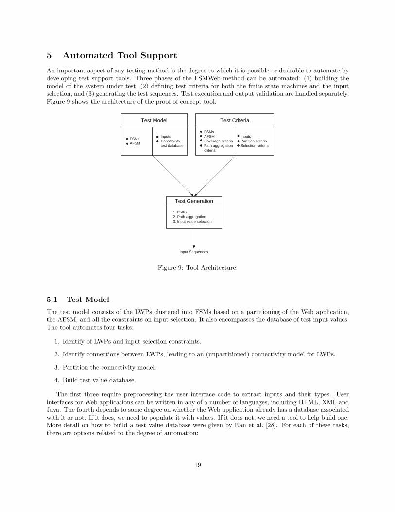
An important aspect of any testing method is the degree to which it is possible or desirable to automate bydeveloping test support tools. Three phases of the FSMWeb method can be automated: (1) building themodel of the system under test, (2) defining test criteria for both the finite state machines and the inputselection, and (3) generating the test sequences. Test execution and output validation are handled separately.Figure 9 shows the architecture of the proof of concept tool.
Test Model
FSMsAFSM
InputsConstraintstest database
Test Criteria
FSMsAFSMCoverage criteriaPath aggregationcriteria
InputsPartition criteriaSelection criteria
Test Generation
1. Paths 2. Path aggregation 3. Input value selection
Input Sequences
Figure 9: Tool Architecture.
5.1 Test Model
The test model consists of the LWPs clustered into FSMs based on a partitioning of the Web application,the AFSM, and all the constraints on input selection. It also encompasses the database of test input values.The tool automates four tasks:
1. Identify of LWPs and input selection constraints.
2. Identify connections between LWPs, leading to an (unpartitioned) connectivity model for LWPs.
3. Partition the connectivity model.
4. Build test value database.
The first three require preprocessing the user interface code to extract inputs and their types. Userinterfaces for Web applications can be written in any of a number of languages, including HTML, XML andJava. The fourth depends to some degree on whether the Web application already has a database associatedwith it or not. If it does, we need to populate it with values. If it does not, we need a tool to help build one.More detail on how to build a test value database were given by Ran et al. [28]. For each of these tasks,there are options related to the degree of automation:
19
1. User controlled. This means that automation is in the form of an editor that allows testers to definewhat set of Web page inputs form an LWP, set connections between them, and tags LWPs thatform a cluster. Many drawing tools (like xfig, visio, or Rational) allow larger objects to be built bygrouping smaller ones together. The testers also need an input constraint editor to define constraintsfor connections between LWPs.
2. Full Automation. A more automated method would be to parse source files such as HTML, XML,and Java and identify sequences of inputs that lead to actions and/or transitions to other parts of theWeb application. The parser can also extract LWPs and transitions between them. Partitioning canbe done automatically through min-cut algorithms or based on coupling measures and thresholds. Forexample, the coupling measure may count the number of incoming edges to a node for an LWP. Ifthe count is higher than a specified threshold, the nodes with edges leading to this LWP must be inthe same cluster as the LWP. While these can automatically partition the application, this may notbe a good fit with a functional partition. In addition, it would not create the role-based partition weused in the example in which services are clustered by type of user, even though some of them are thesame. Defining constraints automatically would require determining semantics of inputs of each LWP.For some types of inputs this may be more difficult.
3. Combination. In combination mode, tools choose initial candidate LWPs, links, and clusters, and theuser then refines the tools’ choices. The underlying philosophy would be to automate what is easy toautomate and to leave things that are difficult to automate for the user to define.
The current prototype falls under category 1, user controlled. However, the FSMs and AFSM are storedin a defined XML format and in the future we plan to write a parser to generate FSMs and AFSMs directlyfrom the program source.
5.2 Test Criteria
As described in Section 4, the tester needs to choose the test criteria. The most obvious for the FSM testsequences are node and edge, although others such as roundtrip [5] or edge-pair [25] could be used.
Criteria for aggregating FSM test sequences also need to be chosen. The cost/benefit tradeoffs of eachchoice versus base choice in Section 4 provide another opportunity for the tester to calibrate the amount oftesting done.
5.3 Test Generation
Test generation uses both the test model and the test criteria. Generation proceeds in three steps:
1. Path selection for each FSM and the AFSM based on the coverage criterion sought. This is easilyautomatable via existing graph algorithms. Path selection algorithms that do not end in an end staterequire the addition of a proper sequence to an end state. Otherwise, the sequence cannot be aggregatedproperly with the follow-on test sequence in the aggregate test sequence.
2. Path aggregation criteria are also easily automatable.
3. Input selection. Input constraints determine what inputs to select and in which order. Partitions andpartition related criteria specify sets of values from which to select. Entries in the database allowsemantically correct values to be selected when two values are related (like user name and password).One issue is satisfiability of constraints and criteria during selection. Some constraints, particularlythe combination of constraints that appear when test sequences are aggregated, are very difficult tosatisfy and others are infeasible. The existance of infeasible test requirements is a problem in all testtechniques and are handled either by approximating (ignoring difficult-to-satisfy requirements) or byhaving the tester solve them by hand. Most practical situations use a combination of both.
20

We have developed a research prototype in Java to support these ideas. It has a graphical editor to inputthe FSMs and the constraint descriptions. It also generates expected outputs in the form of the next state(LWP) to serve as a simple test oracle. Path generation currently includes edge coverage and roundtrip. Weare still working on perfecting input selection. Input selection is currently based on using an input valuedatabase [28]. The resulting sequences of test inputs are made executable by transforming them into anEvalid script. Evalid is a script and script execution tool by Software Research Associates [21].
It is possible that some test sequences are infeasible. This can happen due to an incorrect model, dueto a defect in the Web application, or due to not being able to satisfy the input constraint. While we haveseen examples of the first two in our empirical work, we have yet to encounter the last.
6 Related Work
This section surveys some of the previous work in testing Web applications and generating tests with finitestate machines.
6.1 Test Support for Web Applications
Much of the literature on testing Web applications is in the commercial sector and tests non-functionalaspects of the software. An extensive listing of existing Web test support tools is on a Web site maintainedby Hower [13]. The list includes link checking tools, HTML validators, capture/playback tools, security testtools, and load and performance stress tools. These are all static validation and measurement tools, none ofwhich support functional testing or black box testing. This project addressed problem 1 in Section 1.1.
Kung, Liu, and Hsia [16, 17] developed a test generation method based on multiple models of the appli-cations under test. The models include Object Relation Diagrams, Object State Diagrams, a Script ClusterDiagram, and a Page Navigation Diagram. This model assumes that the source is available, whereas ourresearch does not. Also, this paper uses an enhanced Finite State Machine that includes representation oftest constraints and does not need multiple types of diagrams. Unlike Kung et al. [16, 17], we also representthe FSM via logical, rather than physical Web pages and solve potential state space explosion problemsthrough partitioning and a different approach towards input description on the edges of the FSM. Thisresearch addressed problems 1 and 6 in Section 1.1.
Lee and Offutt [19] describe a system that generates test cases using a form of mutation analysis. Itfocuses on validating the reliability of data interactions among Web-based software components. Specifically,it considers XML based component interactions. This approach tests Web software component interactions,whereas our current research is focused on the Web application level. This research addressed problem 7 inSection 1.1.
Ricca and Tonella [29] proposed a UML model of Web application for high level abstraction. The model isbased entirely on static HTML links and does not incorporate any dynamic aspects of the software. Any Webapplication can be seen as an instance of the UML model. The model is supported by a tool that creates astatic graph based on HTML links and another that creates tests comprised of sequences of URLs. Althoughthe paper claims that the tools can “guarantee that all paths in a Web site” are covered, assumptions aboutdata inputs and lack of information about dynamically created links clearly limit the paths that are covered.
Yang et al. [34, 35] present an architecture for test tools that is directed towards testing Web applications.The architecture consists of five subsystems including test development, test measurement, test execution,test failure analysis and test management. From the paper, it is not clear whether the test architectureincludes new tools or whether it is meant to incorporate existing tools. The FSM modeling-based toolproposed in this paper satisfies the test development and test measurement portion of Yang et al.’s testarchitecture.
Jia and Liu [15] proposes an approach for formally describing tests for Web applications using XML. Aprototype tool, WebTest, was also developed. Their XML approach could be combined with the test criteriaproposed in this paper by expressing the tests in XML.
21

Benedikt, Freire and Godefroid [3] presented VeriWeb, a dynamic navigation testing tool for Web appli-cations. VeriWeb explores sequences of links in Web applications by nondeterministically exploring actionsequences, starting from a given URL. Excessively long sequences of links are limited by pruning paths in aform of path coverage. VeriWeb creates data for form fields by choosing from a set of name-value pairs thatare initialized by the tester. VeriWeb is the most similar work to the ideas presented in this paper. Theprimary difference is in the graphs that are used and the technique applied to reduce their size. VeriWeb’stesting is based on graphs where nodes are Web pages and edges are explicit HTML links, and the size ofthe graphs is controlled by a pruning process. Our technique relies on FSM models of the Web applicationand uses aggregation abstraction of the FSMs to control the size. Thus Benedikt, Freire and Godefroid’sresearch addressed problems 1 and 2 in Section 1.1.
6.2 Test Generation Via Finite State Machines
Test generation via Finite State Machines (FSM) has a long and rich history. Some of the earliest paperswere in the 1970s [5, 12, 14, 27]. The primary focus of these papers was on using FSMs to generate testsfor telecommunication systems that are described in standard finite automata, although much of the workpertained to general graphs. Huang [14] suggested covering each edge (“branch”) in the FSM, and Howden[12] suggested covering complete trips through the FSM, but without looping. Chow [5] suggested generatinga spanning tree from the FSM and then basing test sequences on paths through this tree. Pimont and Rault[27] suggested covering pairs of edges, called “switch cover.” Fujiwara [8] used the term “n-switch” to referto a sequence of edges extending Pimont and Rault’s pairs of edges to arbitrary lengths (and mistakenlyattributing “1-switch”, or switch cover, to Chow and calling it the “W-method”).
Other test generation methods based on FSMs include tour [22], the distinguished sequence method [10],and unique input-output method [30]. Their objectives are to detect output errors based on state transitionsdriven by inputs. FSM based test generation has been used to test a variety of applications including lexicalanalyzers, real-time process control software, protocols, data processing, and telephony.
The key behind using FSMs to support testing seems to be not “what” to do with them (the aboveparagraphs give a plethora of coverage criteria), but in “how” to generate the FSMs. Most of the coveragecriteria date back to the early papers. Some of the more theoretical work from the formal specificationcommunity has involved creating FSMs from formal specifications. Dick and Faivre [7] generated FSMs byanalyzing formal specifications of software expressed in VDM. Derrick and Boiten [6] did the same, butused the formal specification language Z. Luo, Bochmann and Petrenko [20] applied Fujiwara’s method tocommunicating concurrently executing FSMs.
FSMs have also been used to test object oriented programs [9, 18] and designs [24, 31]. Kung et al.[9, 18] extract the FSM from the code using symbolic execution, while Turner and Robson [31] derive theFSM from the design of classes. Offutt and Abdurazik [24] derive tests from UML state charts [11], a formof FSMs. Offutt and Liu [25, 26] developed an FSM model of formal specifications of software. They thendefined several testing criteria on the transitions by adapting control flow-based test criteria such as modifiedcondition/decision coverage (MCDC) [4].
7 Conclusions and Future Work
This paper addresses the problem of automatically testing Web applications at the system level. Thepaper has presented four results. First, the FSMWeb methodology for generating finite state machineswithout using the source code is presented. This is based on a user-level model of the Web application,and a hierarchical aggregation of detailed FSMs. Second, a procedure for generating tests from the FSMs isdeveloped. This procedure uses standard coverage criteria on the FSMs, and a novel technique for aggregatingtests defined for lower level FSMs into tests for aggregate FSMs. Third, a collection of constraints on inputvalues are used to generate user input data in a semi-automatic fashion. The data is chosen from a collectionof possible values provided by the tester, and the constraints are used to ensure that the data is valid for thetest requirements. Fourth, the testing methodology has been demonstrated by a case study on a moderately-
22

sized Web application, a course student information system. Although the example is small enough to fit ina paper, the abstraction and aggregation that are implicit in the method provides built-in scalability.
A research prototype implementation has been written in Java that generates executable Evalid scripts[21] for the application.
7.1 Limitations and Future Work
When considering the problems listed in Section 1.1, the FSMWeb technique addresses problems 1, 2, 3, 4,and 6. At the tester’s discretion, problem 5 can be addressed by adding transitions to the Application FSM.
We have not addressed the “oracle” problem, that is, of deciding if the results are correct. This isparticularly difficult with Web applications because of the low observability. Some of the output is sent backto the user as HTML documents, but Web applications also change state on the server, in the database, andsend messages to other Web applications and services. Tracking these kinds of outputs is very difficult andwe are not aware of any research that has addressed this problem as yet.
One limitation of the FSMWeb technique is that it has somewhat limited support for unanticipated usercontrolled transitions, called operational transitions [33]. This includes a user going directly to an internalWeb page with a bookmark or URL rewriting and unanticipated back and forward transitions and is listed asproblem 4 in Section 1.1. While these types of transitions can certainly be modeled in the application FSMs,doing so has the potential to significantly increase the number of transitions. Before this technique can beused to test these types of transitions, a method will have to be found to model operational transitions inan affordable manner. This could be as straightforward as keeping a list of potential operational transitionsand selecting them an various points in a test sequence. This problem is addressed in separate research byWu and Offutt [33]; in the future we will look into combining the two techniques. We plan to investigateerror recovery testing by investigating the value mutating constraints and FSMs.
Logical web pages are currently identified by hand. However, they can be extracted from HTML or fromsoftware that creates the HTML through fairly simple parsing.
The FSMWeb technique still has a number of open questions and issues left to address. Current work islargely focusing on automation and evaluation. The tool is in a preliminary stage, but work on it is ongoing.The first step is to build the test model with as little user input as possible. We are working on algorithms toautomatically determine logical Web pages and then to derive finite state machines based on the links. Wehope to recognize clusters automatically, perhaps based on the site navigation layout. Some information canalso be gleaned from design notations like UML documents. We are also developing software that combineuser control with automation.
With expanded tool development, we plan to empirically evaluate this method, especially with regardsto the impact of various testing criteria and input selection criteria on the complexity and number of testcases. Empirical studies will also be used to evaluate the ability of this approach to detect faults.
Section 4 discussed the problem of combining test sequences from lower level FSMS into aggregatetest sequences. Rather than choosing to combine all lower level test sequences, which will probably beimpractical, we have suggested two combination strategies. One goal of our experimentation is to evaluatethose combination strategies in terms of their cost/benefit tradeoffs and ability to help find faults.
One of the open questions about our technique is how much the human inputs impacts the results. Forexample, the CSIS model was based on whether the user is a student, TA, or professor. The three types ofusers share a number of functions, so another valid model might start by looking at those functions, andconsidering the type of user to just be a parameter. This is a general risk of allowing human input intoany test process; the human can provide a very large amount of useful information, but then some of theautomation and repeatability is lost. One question we will explore is how much of an effect these decisionshave on the testing of the software.
Test generation can also be further refined, specifically by recognizing and using relationships amonginputs as constraints. For example, for a given user name, only one password is valid. A previous tool by thefirst author, SLEUTH [32], represented constraints like this through sets of related values. If a database ofinputs is available, then it can be used to support this type of constraint. For example, if the Web application
23

has a database of users and user information, the test generator can index into the database, query the userrecord and identify the appropriate password after a user name has been selected. The test model needsto account for these relationships. If the database is not available, a special-purpose test database will becreated as defined by Ran et al. [28]. Note that this approach no longer needs to be concerned with syntaxfor an input (for example, a birth year may have to be a four digit number between 1900 and 2002). Ineffect, we are trading off populating a test database with input values against generating them dynamically.Many Web applications use databases for key inputs such as users and orders, so the test environment canuse them to simplify test generation. We also assume that testers have full access to such a database if itexists.
References
[1] Paul Ammann and A. Jefferson Offutt. Using formal methods to derive test frames in category-partitiontesting. In Proceedings of the Ninth Annual Conference on Computer Assurance (COMPASS 94), pages69–80, Gaithersburg MD, June 1994. IEEE Computer Society Press.
[2] Paul Ammann and Jeff Offutt. Coverage Criteria for Software Testing. In preparation, 2004.
[3] Michael Benedikt, Juliana Freire, and Patrice Godefroid. VeriWeb: Automatically testing dynamic Websites. In Proceedings of 11th International World Wide Web Conference (WWW’2002), Honolulu, HI,May 2002.
[4] J. J. Chilenski and S. P. Miller. Applicability of modified condition/decision coverage to software testing.Software Engineering Journal, pages 193–200, September 1994.
[5] T. Chow. Testing software designs modeled by finite-state machines. IEEE Transactions on SoftwareEngineering, SE-4(3):178–187, May 1978.
[6] John Derrick and Eerke Boiten. Testing refinements of state-based formal specifications. SoftwareTesting, Verification, and Reliability, 9(1):27–50, December 1999.
[7] J. Dick and A. Faivre. Automating the generation and sequencing of test cases from model-basedspecifications. In Proceedings of FME ’93: Industrial-Strength Formal Methods, pages 268–284, Odense,Denmark, 1993. Springer-Verlag Lecture Notes in Computer Science Volume 670.
[8] S. Fujiwara, G. Bochmann, F. Khendek, M. Amalou, and A. Ghedasmi. Test selection based on finitestate models. IEEE Transactions on Software Engineering, 17(6):591–603, June 1991.
[9] J. Z. Gao, D. Kung, P. Hsia, Y. Toyoshima, and C. Chen. Object state testing for object-orientedprograms. In 19th Computer Software and Applications Conference (COMPSAC 95), pages 232–238,Dallas, TX, August 1995.
[10] G. Gonenc. A method for the design of fault-detection experiments. IEEE Transactions on Computers,C-19:155–558, June 1970.
[11] The Object Management Group. OMG unified modeling language specification, 1999. Version 1.3,OMG, 1999.
[12] W. E. Howden. Methodology for the generation of program test data. IEEE Transactions on SoftwareEngineering, SE-24, May 1975.
[13] Rick Hower. Web site test tools and site management tools. Software QA and Testing Resource Center,2002. www.softwareqatest.com/qatweb1.html (accessed November 2003).
[14] J. C. Huang. An approach to program testing. ACM Computing Surveys, 7(3):113–128, September1975.
24

[15] Xiaoping Jia and Hongming Liu. Rigorous and automatic testing of Web applications. In 6th IASTEDInternational Conference on Software Engineering and Applications (SEA 2002), pages 280–285, Cam-bridge, MA, November 2002.
[16] D. Kung, C. H. Liu, and P. Hsia. A model-based approach for testing Web applications. In Proc. ofTwelfth International Conference on Software Engineering and Knowledge Engineering, Chicago, IL,July 2000.
[17] D. Kung, C. H. Liu, and P. Hsia. An object-oriented Web test model for testing Web applications.In Proc. of IEEE 24th Annual International Computer Software and Applications Conference (COMP-SAC2000), pages 537–542, Taipei, Taiwan, October 2000.
[18] D. Kung, N. Suchak, J. Gao, P. Hsia, Y. Toyoshima, and C. Chen. On object state testing. In EighteenthAnnual International Computer Software & Applications Conference, pages 222–227, Los Alamitos, CA,1993. IEEE Computer Society Press.
[19] Suet Chun Lee and Jeff Offutt. Generating test cases for XML-based Web component interactionsusing mutation analysis. In Proceedings of the 12th International Symposium on Software ReliabilityEngineering, pages 200–209, Hong Kong China, November 2001. IEEE Computer Society Press.
[20] G. Luo, G. v. Bochmann, and A. Petrenko. Test selection based on communicating nondeterministicfinite-state machines using a generalized Wp-method. IEEE Transactions on Software Engineering,20(2):149–162, February 1994.
[21] E. Miller. Evalid. Software Research Associates, San Francisco, CA, 2003.
[22] S. Naito and M. Tsunoyama. Fault detection for sequential machines by transition tours. In ProceedingsFault Tolerant Computing Systems, pages 238–243. IEEE Computer Society Press, 1981.
[23] Jakob Nielsen. Designing Web Usability. New Riders Publishing, 2000.
[24] Jeff Offutt and Aynur Abdurazik. Generating tests from UML specifications. In Proceedings of theSecond IEEE International Conference on the Unified Modeling Language (UML99), pages 416–429,Fort Collins, CO, October 1999. Springer-Verlag Lecture Notes in Computer Science Volume 1723.
[25] Jeff Offutt, Shaoying Liu, Aynur Abdurazik, and Paul Ammann. Generating test data from state-basedspecifications. The Journal of Software Testing, Verification, and Reliability, 13(1):25–53, March 2003.
[26] Jeff Offutt, Yiwei Xiong, and Shaoying Liu. Criteria for generating specification-based tests. In Pro-ceedings of the Fifth IEEE International Conference on Engineering of Complex Computer Systems(ICECCS ’99), pages 119–131, Las Vegas, NV, October 1999. IEEE Computer Society Press.
[27] S. Pimont and J. C. Rault. An approach towards reliable software. In Proceedings of the 4th InternationalConference on Software Engineering, pages 220–230, Munich, Germany, 1979.
[28] L. Ran, C. Dyreson, and A. Andrews. AutoDBT: A framework for database-driven testing of Webapplications. Master’s thesis, Department of EE and CS, Washington State University, Pullman WA,2004.
[29] F. Ricca and P. Tonella. Analysis and testing of Web applications. In 23rd International Conferenceon Software Engineering (ICSE ‘01), pages 25–34, Toronto, CA, May 2001.
[30] K. Sabnani and A. Dahbura. A protocol testing procedure. Computer Networks and ISDN Systems,14(4):285–297, 1988.
[31] C. D. Turner and D. J. Robson. The state-based testing of object-oriented programs. In Proceedingsof the 1993 IEEE Conference on Software Maintenance (CSM-93), pages 302–310, Montreal, Quebec,Canada, September 1993.
25

[32] A. von Mayrhauser and R. Mraz. Using domain models for system testing. In Advances in Computers,volume 49, pages 143–190. Academic Press, 1999.
[33] Ye Wu, Jeff Offutt, and Xiaochen Du. Modeling and testing of dynamic aspects of Web applications.Submitted, 2003.
[34] J. Yang, J. Huang, F. Wang, and W. Chu. An object-oriented architecture supporting Web applicationtesting. In First Asian-Pacific Conference on Quality Software (APAQS ’99), pages 122–129, Japan,December 1999.
[35] Ji-Tzay Yang, Jiun-Long Huang, Fen-Jian Wang, and William C. Chu. Constructing an object-orientedarchitecture for Web application testing. Journal of Information Science and Engineering, 18(1):59–84,January 2002.
26

A Appendix: BNF Grammar for Input Selection Constraints
The table below gives the grammar for our input constraint language. At the highest level, a constraintconsists of one or more input choices, followed by zero or more order constraints, followed by zero or morepropagation constraints.
There are three types of input choices: required, optional, and choice. Required and optional inputs arespecified by the operators R and O, and are followed by a list of parameters. Parameters are named inputsdesignated by strings, and may optionally be constrained to a particular value (for example Name=’AlanTuring’). Choice inputs are specified by the operator C followed by an integer (for example C3) and optionalbound designator (+ or -), followed by a list of input parameters.
The choice operator is used to place a constraint on the number of inputs that may be selected. Forexample, C3 requires exactly three inputs to be selected from the list. Lower and upper bounds are specifiedusing the bound designators. For example, C4- limits the number of selected inputs to at most four. Similarly,C5+ requires at least five inputs be selected. The number of inputs specified by a choice operator must beconsistent with the number of choices in the parameter list.
Order constraints are specified using the sequential and any order operators S and A, followed by aconstraint list. An S order constraint requires that the inputs in the corresponding constraint list occurin their order of appearance in the list. For example, the constraint S(Id, Password, Submit) specifiesthat Id must be entered first, followed by Password, and finally by Submit. Similarly, any requires thatall inputs in the constraint list be entered, but their order is unspecified. For example, A(First, Middle,Last) requires that First, Middle, and Last appear as inputs, but in any order. Thus, the followingare valid entry sequences: First;Middle;Last, Last;First;Middle, and so on. Note that a constraint listconsists of elements that are either input choices or other order constraints (that is, nested order constraints).For example, the two entry sequences in the preceding paragraph could be specified as A(S(First, Middle,Last), S(Last, First, Middle)). An input used in an order constraint must be specified in the list ofinput choices.
Propagation constraints specify a list of inputs whose current values may or may not be reused. Thelatter are specified by the continue operator followed by a list of inputs. Similarly, the single operator isused to specify inputs whose values may not be used again. Note that inputs in either list are required toalso be specified in the list of input choices.
27

Constraint ( InputChoices [ OrderConstraint ] [ PropagationConstraints ] ) — NoneNone noneInputChoices InputChoice [ InputChoice ]*InputChoice RequiredInput — OptionalInput — ChoiceInputRequiredInput Required InputListRequired RInputList Left RequiredParameterList RightLeft (Right )RequiredParameterList Parameter [ AdditionalParameter ]*Parameter SimpleParameter [ FixedConstraint ]SimpleParameter stringFixedConstraint Equals ValueEquals =Value Quote string QuoteQuote ’AdditionalParameter Comma ParameterComma ,OptionalInput Optional InputListOptional OChoiceInput Choose Number [Bound ] Left ParameterList RightChoose CBound - — +Number integerOrderConstraint Order ConstraintListConstraintParameterList ConstraintParameter [ AdditionalConstraintParameter ]*ConstraintParameter SimpleParameter — OrderConstraintConstraintList Left ConstraintParameterList RightAdditionalConstraintParameter Comma ConstraintParameterOrder AnyOrder — SequentialOrderAnyOrder ASequentialOrder SPropagationConstraints [ ContinueUseList ] [ SingleUseList ]ContinueUseList ContinueUse SimpleParameterListContineUse continueSingleUseList SingleUse SimpleParameterListSingleUse singleSimpleParameterList SimpleParameter [ AdditionalSimpleParameter ]*AdditionalSimpleParameter Comma SimpleParameter
28