testo 310 · flue gas analyzer - ivy tools, inc. · testo. > any further or ... • only use in...
TRANSCRIPT
testo 310 · Flue gas analyzer
Instruction manual

2

1 Contents
3
1 Contents 1 Contents ................................................................................................... 3 2 Safety and the environment .................................................................... 5
2.1. About this document ........................................................................ 5 2.2. Ensure safety................................................................................... 6 2.3. Protecting the environment .............................................................. 7
3 Specifications .......................................................................................... 8 3.1. Use .................................................................................................. 8 3.2. Technical data ................................................................................. 8
3.2.1. Measurement ranges and resolution .................................................................. 8 3.2.2. Other instrument data ......................................................................................... 9
4 Product description ............................................................................... 10 4.1. Measuring instrument .................................................................... 10
4.1.1. Front view ..........................................................................................................10 4.1.2. Keypad ..............................................................................................................10 4.1.3. Display...............................................................................................................11 4.1.4. Connections ......................................................................................................13 4.1.5. Condensate outlet/interface ..............................................................................13 4.1.6. Rear view ..........................................................................................................14
4.2. Flue gas probe ............................................................................... 15 4.3. Area versions................................................................................. 15 4.4. Reading display ............................................................................. 17
5 Using the product .................................................................................. 19 5.1. Mains unit / rechargeable battery .................................................. 19
5.1.1. Charging the rechargeable battery ...................................................................19 5.1.2. Mains operation.................................................................................................20
5.2. Performing settings ........................................................................ 20 5.2.1. Instrument configuration menu / commissioning ..............................................20 5.2.2. Measurements configuration menu ..................................................................22
5.3. Measuring ...................................................................................... 23 5.3.1. Preparing for measurement ..............................................................................23
5.3.1.1. Zeroing phases ...................................................................................23 5.3.1.2. Using the flue gas probe ....................................................................23 5.3.1.3. Setting fuel .........................................................................................24
5.3.2. Flue gas ............................................................................................................24 5.3.3. Ambient CO .......................................................................................................25 5.3.4. Draught measurement ......................................................................................26 5.3.5. Differential pressure ..........................................................................................26

1 Contents
4
6 Maintaining the product ....................................................................... 29 6.1. Cleaning the measuring instrument .............................................. 29 6.2. Cleaning the flue gas probe .......................................................... 29 6.3. Draining the condensate container ............................................... 29 6.4. Checking / replacing the particle filter ........................................... 30
7 Tips and assistance .............................................................................. 31 7.1. Questions and answers ................................................................ 31 7.2. Accessories and spare parts ......................................................... 33

2 Safety and the environment
5
2 Safety and the environment
2.1. About this document
Use > Please read this documentation through carefully and
familiarize yourself with the product before putting it to use. Pay particular attention to the safety instructions and warning advice in order to prevent injuries and damage to the products.
> Keep this document to hand so that you can refer to it when necessary.
> Hand this documentation on to any subsequent users of the product.
Warnings Always pay attention to information that is marked by the following warnings with warning pictograms. Implement the specified precautionary measures.
Representation Explanation
CAUTION indicates potential minor injuries
NOTICE indicates circumstances that may lead to damage to the products
Symbols and writing standards
Represen-tation
Explanation
2 Safety and the environment
6
Note: Basic or further information.
1. ... 2. ...
Action: more steps, the sequence must be followed.
> ... Action: a step or an optional step.
- ... Result of an action.
[OK] Control keys of the instrument or buttons of the program interface.
2.2. Ensure safety
> Only operate the product properly, for its intended purpose and within the parameters specified in the technical data. Do not use any force.
> Do not operate the instrument if there are signs of damage at the housing, mains unit or feed lines.
> Do not perform contact measurements on non-insulated, live parts.
> Do not store the product together with solvents. Do not use any desiccants.
> Carry out only the maintenance and repair work on this instrument that is described in the documentation. Follow the prescribed steps exactly. Use only original spare parts from Testo.
> Any further or additional work must only be carried out by authorised personnel. Testo will otherwise refuse to accept responsibility for the proper functioning of the measuring instrument after repair and for the validity of certifications.
> Only use the device in closed, dry rooms and protect it from rain and moisture.
> Temperatures given on probes/sensors relate only to the measuring range of the sensors. Do not expose handles and feed lines to any temperatures in excess of 70 °C unless they are expressly permitted for higher temperatures.
> The objects to be measured or the measurement environment may also pose risks: Note the safety regulations valid in your area when performing the measurements.

2 Safety and the environment
7
> Improper use of rechargeable batteries can lead to destruction or injuries by means of current surges, fire or escaping chemicals. The following instructions must be observed to avoid such hazards: • Only use in accordance with the directions in the instruction
manual. • Do not short, take apart or modify. • Do not expose to heavy impacts, water, fire or temperatures
above 60 °C. • Do not store in the proximity of metal objects. • Do not use leaky or damaged rechargeable batteries. In the
event of contact with battery acid: Thoroughly wash affected area with water and consult a doctor, if necessary.
• Only charge in the instrument or the recommended charging station.
• Immediately stop the charging process if this is not completed in the given time.
• In the event of improper function or signs of overheating, immediately remove the rechargeable battery from the measuring instrument/charging station. Caution: Rechargeable battery may be hot!
2.3. Protecting the environment
> Dispose of faulty rechargeable batteries/spent batteries in accordance with the valid legal specifications.
> At the end of its useful life, send the product to the separate collection for electric and electronic devices (observe local regulations) or return the product to Testo for disposal.

3 Specifications
8
3 Specifications
3.1. Use
The testo 310 is a handheld measuring instrument for the professional flue gas analysis of combustion plants: • Small combustion plants (oil, gas, wood, coal) • Low-temperature and condensing boilers • Gas water heaters These systems can be adjusted using the testo 310 and checked for compliance with the applicable limit values. The following tasks can also be carried out using the testo 310: • Regulating the O2, CO and CO2 values in combustion plants
for the purpose of ensuring optimal operation. • Draught measurement. • Measuring and regulating the gas flow pressure in gas water
heaters. • Ambient CO measurement. The testo 310 must not be used: • as a safety (alarm) device
3.2. Technical data
3.2.1. Measurement ranges and resolution Measure-ment parameter
Measurement range
Resolution Accuracy Response time t90 @ 22 °C
O2 0.0 to 21.0 Vol.% 0.1 vol.% ±0.2 vol.% 30s
CO 0 to 4000 ppm 1 ppm ±20 ppm (0...400 ppm) ±5% v. Mw. (401...2000 ppm) ±10% v. Mw. (2001...4000 ppm)
60s
COamb 0 to 4000 ppm 1 ppm ±20 ppm (0...400 ppm) ±5% v. Mw. (401...2000 ppm) ±10% v. Mw. (2001...4000 ppm)
60s
Draught -20.00 to 20.00 hPa
0.01 hPa ± 0.03hPa (-3.00 to 3.00 hPa) ±1.5% of meas. val. (rest of range)
-

3 Specifications
9
Measure-ment parameter
Measurement range
Resolution Accuracy Response time t90 @ 22 °C
ΔP -40.0 to 40.0 hPa 0.1 hPa ± 0.5hPa
-
Flue gas temperature
0.0 to 400.0 °C 0.1°C
± 1°C (0.0 to 100.0°C) ± 1.5% of meas. val. (>100°C)
<50s
Ambient temperature
-20.0 to 100.0 °C 0.1°C
± 1°C
<50s
3.2.2. Other instrument data Flue gas analyser
Feature Values Storage and transport temperature
-20 to 50 °C
Operating temperature
-5 to 45 °C
Power supply Rechargeable battery: 1500mAh Mains unit: 5 V/1 A
Protection class IP40 Weight incl. probe approx. 700g Dimensions 201 x 83 x 44 mm Battery charge time approx. 8 h Rechargeable battery life
> 8h (pump on, 20°C ambient temperature)
EU Directive 2004/108/EC Warranty Measuring instrument, flue gas probe: 24
months Thermocouple: 12 months Sensors O2, CO: 24 months, Rechargeable battery: 12 months
Terms of warranty Terms of warranty: see website www.testo.com/warranty

4 Product description
10
4 Product description
4.1. Measuring instrument 4.1.1. Front view
1 Display 2 Function keys 3 Keypad
4.1.2. Keypad
Button Functions
[ ] Switch measuring instrument on / off
[OK] Example
Function key (orange, 3x), relevant function is shown on the display
[▲] Increase value, select parameter [▼] Decrease value, select parameter

4 Product description
11
Button Functions [esc] Back, cancel print process
[ ] Switch display light on/off
[ ] Transmit data to the Testo protocol printer.
4.1.3. Display
1 Measurement type (an arrow marks the measurement type that is activated): Icon Measurement
Flue gas (icon visible when the instrument is switched off)
Ambient CO (icon visible when the instrument is switched off)
Draught (icon visible when the instrument is switched off)
Differential pressure (icon visible when the instrument is switched off)

4 Product description
12
2 Status: Icon Meaning
Measuring gas pump (icon visible when the instrument is switched off) The inner segments light up alternately when the measuring gas pump is running.
Error Flashes when an error occurs, an error code is also displayed.
Print Lights up during data transmission to the report printer
Open configuration menu
Fuel type / fuel number Depending on the set fuel, one of the icons (solid fuel, oil, gas) and the associated fuel number lights up.
, , , Battery capacity. Indication of the remaining capacity of the rechargeable battery by fill level of the battery icon: • 3 segments 75-100% • 2 segments 50-75% • 1 segment 25-50% • no segment <25%
3 Reading display line 1 See Area versions, page 15. 4 Reading display line 2 See Area versions, page 15. 5 Function key assignment:
Icon Possible assignment
Left function key: Select measurement type
OK Start Stop
Middle function key: Confirm input Start measurement Stop measurement

4 Product description
13
Icon Possible assignment Set
Right function key: Open configuration menu Switch to the next parameter:
4.1.4. Connections
1 Charging socket for mains unit (Micro USB) 2 Cable to the flue gas probe 3 Gas outlet
4.1.5. Condensate outlet/interface
1 Infrared interface
2 Condensate outlet

4 Product description
14
4.1.6. Rear view
1 Attachment for carrying strap 2 Condensate trap 3 Magnetic holder 4 Gas outlet 5 Magnetic holder
WARNING Magnetic field May be harmful to those with pacemakers. > Keep a minimum distance of 10 cm between
pacemaker and instrument.
ATTENTION
Magnetic field Damage to other devices! > Keep a safe distance away from products which could
be damaged by the effects of magnetism (e.g. monitors, computers or credit cards).

4 Product description
15
4.2. Flue gas probe
1 Thermocouple 2 Probe shaft 3 Probe handle 4 Connecting cable 5 Removable filter chamber with window, particle filter, and
sealing plug for differential pressure measurement
4.3. Area versions The instrument can be configured for 5 area versions. Country-specific calculation formulas, associated measurement parameters and fuels are activated with this setting. Similarly, the setting influences the date and time format. The area version is set in the instrument configuration menu / commissioning, see Instrument configuration menu / commissioning, page 20.

4 Product description
16
Area version (ArEA )
Countries (recom-mendation)
Parameters Fuels
1 USA, HU, IN, KR
Line 1: O2, T, CO , P1, P2, uCO Line 2: CO, Eff, T, EXA, CO2
nAt GAS – Natural gas ProP GAS – Propane FUEL OIL2 – Fuel oil 2 Bioh 5 – Biomass 5% Uood 20 – Wood 20%
2 GB, RU, DK, AU, JP, CN
Line 1: rat, O2, T, P1, CO , P2, uCO Line 2: CO2, CO, EXA, Eff.net, Eff.gross,
T, O2
nAt GAS – Natural gas LPG GAS – LPG ProP GAS – Propane But GAS – Butane LI OIL – EL fuel oil CEro SEnE – Kerosene HE OIL – Heavy fuel oil Uood PELL - Wood pellets
3 NL, SE, TR, RO
Line1: O2, P1, T, GI, uCO, P2 Line 2: CO, CO2,
T, Eff, qA, λ, CO
nAt Hb – Natural gas Hb nAt Ho – Natural gas Ho ProP Hb – Propane Hb ProP Ho – Propane Ho but Ho – Butane Ho LPG Ho – LPG Ho LI OIL – EL fuel oil Uood PELL – Wood pellets
4 DE, AT, CH, CZ, FR, ES, BE, PL, PT, AR, BR
Line1: T, CO, uCO,
T, O2, P1, P2, CO Line 2: O2, qA, CO2, Eff, λ, T, T
nAt GAS - Natural gas ProP GAS - Propane but GAS - Butane CoO GAS - Coke oven gas Toun GAS - Town gas GAS OIL – Gasoleo A LI OIL - EL fuel oil HE OIL - Heavy fuel oil Uood 15 - Wood 15%

4 Product description
17
Area version (ArEA )
Countries (recom-mendation)
Parameters Fuels
5 IT Line1:: O2, T, T, uCO, UnI Line 2: CO, λ, CO2, qA, Eff gross, T, O2, UnI
nAt GAS – Natural gas GPL – Propane but GAS – Butane GAS OIL – Gasoleo A OIL – Heavy fuel oil Wood PELL – Wood pellets Wood - Wood
4.4. Reading display Display Measurement parameter
T Ambient temperature
T Flue gas temperature
CO Carbon monoxide
O2 Oxygen
CO Ambient carbon monoxide
qA Flue gas loss without due consideration of the calorific value range
Eff.net Net efficiency (without due consideration of the calorific value range)
Eff.gross / Eff* Gross efficiency (with due consideration of the calorific value range)
Eff. Efficiency
λ Air ratio
P2 Differential pressure
CO2 Carbon dioxide
P1 Flue draught
uCO Carbon monoxide undiluted
rat Ratio
4 Product description
18
Display Measurement parameter
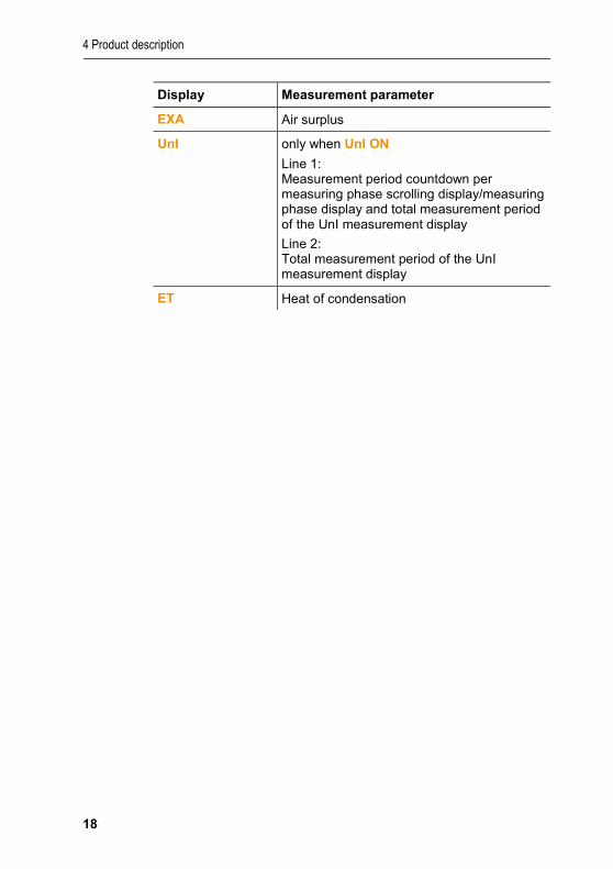
EXA Air surplus
UnI only when UnI ON Line 1: Measurement period countdown per measuring phase scrolling display/measuring phase display and total measurement period of the UnI measurement display Line 2: Total measurement period of the UnI measurement display
ET Heat of condensation

5 Using the product
19
5 Using the product
5.1. Mains unit / rechargeable battery
The rechargeable battery is permanently installed and can only be changed by a Testo service centre. The measuring instrument is supplied with a partially charged rechargeable battery. > Charge the rechargeable battery fully before using the
measuring instrument.
5.1.1. Charging the rechargeable battery The rechargeable battery can only be charged at an ambient temperature of ±0 to +35°C. If the battery has been discharged completely, the charging time at room temperature is approx. 5-6 hrs.
Charging in the measuring instrument
1. Connect the plug of the mains unit to the mains unit socket on the measuring instrument.
2. Connect the mains plug of the mains unit to a mains socket. - The charging process will start. The charge status will be shown
on the display. The charging process will stop automatically when the battery is fully charged.
Battery care > Do not fully exhaust the rechargeable battery. > Only store instrument with battery charged and at low
temperatures, but not below 0°C (best storage conditions with a charge level of 50-75% = 2 segments, at an ambient temperature of 10-20°C, recharge completely before use).
> The rechargeable battery life depends on the storage, operating and ambient conditions. The available useful life of the rechargeable battery reduces more and more with frequent use. If the useful life is significantly shortened, the rechargeable battery should be replaced.

5 Using the product
20
5.1.2. Mains operation 1. Connect the plug of the mains unit to the mains unit socket on
the measuring instrument. 2. Connect the mains plug of the mains unit to a mains socket. - The measuring instrument is powered by the mains unit. - If the measuring instrument is switched off, the charging
process starts automatically. Switching the measuring instrument on has the effect of stopping the battery charging and the measuring instrument is then powered via the mains unit.
5.2. Performing settings
The instrument has two different configuration menus. The menu that is opened depends on the instrument status when called up.
5.2.1. Instrument configuration menu / commissioning When the instrument is switched on initially, the configuration menu is opened automatically. Following initial commissioning, the configuration menu can also be opened again by pressing the right function key [set] during the instrument's initialisation phase (a duration of approx. 4 seconds). The values for area version, measuring units, time and date can be set.
Making settings
1. Switch the instrument on: Hold down [ ], until all segments are shown on the display.
2. Open instrument configuration menu: Press right function key [set] during the initialisation phase.

5 Using the product
21
3. Make settings:
Use [esc] to revert to the previous parameter at any time.
Display / parameter
Explanation
ArEA (area version)
Selecting the area version activates different calculation formulas and associated measurement parameters, see Area versions, page 15. > Select area version code: [▲] and [▼]. > Switch to the next parameter: [OK].
UnI Only when area version 5 is selected Measurement procedure according to UnI norm: activate [On] / deactivate[OFF].
Unit of pressure
> Select the unit: [▲] and [▼]. > Switch to the next parameter: [OK].
Unit of temperature
> Select the unit: [▲] and [▼]. > Switch to the next parameter: [OK].
Setting the time
> Set values: [▲] and [▼]. > Switch selection between hour, minute
(tens) and minute (single units): []. > Switch to the next parameter: [OK].
Setting the date
> Set values: [▲] and [▼]. > Switch selection between year (tens), year
(single units), month, day (tens) and day (single units): [].
> Exit the configuration menu: [OK].

5 Using the product
22
5.2.2. Measurements configuration menu This configuration menu enables you to make important settings relating to a measurement. Fuels and measuring units can be set.
Press right function key ([set]) after the instrument's initialisation phase.
1. Switch the instrument on: Hold down [ ], until all segments are shown on the display.
2. Open Measurements configuration menu: Press right function key ([set]).
3. Make settings:
Use [esc] to revert to the previous parameter at any time.
Display / parameter
Explanation
Fuel Selecting the area version activates different calculation formulas and measurement parameters, see Area versions, page 15. > Select the fuel: [▲] and [▼]. > Switch to the next parameter: []. > Exit the configuration menu: [OK].
UnI Only when area version 5 is selected Measurement procedure according to UnI norm: activate [On] / deactivate[OFF].
Unit of pressure
> Select the unit: [▲] and [▼]. > Switch to the next parameter: [OK].
Unit of temperature
> Select the unit: [▲] and [▼]. > Exit the configuration menu: [OK].

5 Using the product
23
5.3. Measuring
5.3.1. Preparing for measurement 5.3.1.1. Zeroing phases
Gas sensors If flue gas measurement ( ) or ambient CO measurement ( ) is configured, the gas sensors are zeroed when the instrument is switched on (zeroing phase).
The flue gas probe must be in the open air during the zeroing phase!
Pressure sensor
If draught measurement ( )or differential pressure measurement ( ) is configured, the pressure sensor is zeroed when the instrument is switched on (zeroing phase).
Measuring the combustion air temperature During the zeroing phase, the temperature is measured via the thermocouple of the flue gas probe. This temperature is permanently accepted by the instrument once the zeroing phase has been completed. All dependent parameters are calculated using this value. However, ensure that the flue gas probe is near the intake duct of the burner during the zeroing phase.
5.3.1.2. Using the flue gas probe
Checking the thermocouple
The thermocouple of the flue gas probe must not lie against the probe cage. > Check before use. Bend the thermocouple back if necessary.

5 Using the product
24
Aligning the flue gas probe
The flue gas must be able to flow freely past the thermocouple. > Align the probe by turning it as required.
The tip of the probe must be in the core current of the flue gas flow. > Align the flue gas probe in the flue gas duct so that the tip is in
the core current (area of the highest flue gas temperature).
5.3.1.3. Setting fuel To carry out a flue gas measurement, the fuel must be set correctly, see Measurements configuration menu, page 22.
5.3.2. Flue gas Select measurement type > Select : [ ] → [OK].
Carry out the measurement (area version 1 – 4, area version 5 with setting UnI OFF) 1. Start measurement: [Start].
- The readings are displayed. > Change reading display line 1: [▲]. > Change reading display line 2: [▼]. 2. Quit measurement: [Stop]. > Remove flue gas probe from the flue gas duct and purge with
fresh air.

5 Using the product
25
Carry out measurement (area version 5 with setting UnI ON) To calculate a mean value, a series of measurements is carried out with 3 measuring phases (UnI 1 – UnI 3), each lasting 2 min. and 2 sec. 1. Start measurement: [Start]. - The readings are displayed. > Edit reading display line 1: [▲]. - Measurement parameters, measurement period countdown per
measuring phase / measuring phase display, total measurement period and readings are displayed.
> Edit reading display line 2: [▼]. - Measurement parameters, total measurement period and
readings are displayed. Option > End measurement before the measurement period has
lapsed: [Stop]. - Current readings display.
2. Once the measurement period has lapsed, the measurement stops automatically.
> Scroll through measurement result line 1: [▲]. - Uni measurement mean values display. > Scroll through measurement result line 2: [▼]. - Uni measurement mean values display. 3. Remove flue gas probe from the flue gas duct and purge with
fresh air.
5.3.3. Ambient CO
Cigarette smoke influences the measurement by more than 50 ppm. The breath of a smoker influences the measurement by about 5 ppm. The probe must be in the open air (CO-free) during the zeroing phase!
Select measurement type > Select : [ ] → [OK].
Carry out the measurement 1. Start measurement: [Start].
- The reading is displayed. 2. Quit measurement: [Stop].

5 Using the product
26
3.
5.3.4. Draught measurement
Do not measure for longer than 5 min, as a drift of the pressure sensor means that the readings could be outside the tolerance limits.
Select measurement type > Select : [ ] → [OK].
Performing the measurement - The flue gas probe must be outside the flue. 1. Start measurement: [Start]. - Draught zeroing is carried out. 2. After zeroing, position the flue gas probe in the core current
(area of the highest flue gas temperature). The indication of the measured flue gas temperature in line 2 helps when positioning the probe.
- The reading is displayed. 3. Quit measurement: [Stop].
5.3.5. Differential pressure WARNING
Dangerous mixture of gases Danger of explosion! > Before measurement close the gas path with the sealing plug,
as described below! > Make sure there are no leaks between the sampling point and
the measuring instrument. > Do not smoke or use naked flames during measurement.
Do not measure for longer than 5min, as a drift of the pressure sensor means that the readings could be outside the tolerance limits.
Select measurement type
> Select : [ ] → [OK]. - PLUG appears. > Close the gas path with the sealing plug. Please see the
description below.

5 Using the product
27
Prepare for measurement
1. Open filter chamber of the flue gas probe: turn it gently anti-
clockwise.
2. Remove particle filter (1). 3. Remove the sealing plug (2) in the filter chamber from the
holder.
4. Close the gas path with the sealing plug. 5. Check that the sealing plug is fitted tightly. It should not yield at
all on being tugged gently.

5 Using the product
28
CAUTION Hot probe shaft! Risk of burns! > Allow the probe shaft to cool down after a measurement,
before touching it! > Only attach the silicone hose to the probe shaft once it has
cooled down!
6. Fit silicone hose onto the probe shaft of the flue gas probe. The probe shaft openings must be closed.
Carry out the measurement - The silicone hose must be clear (pressureless, no kinks). 1. Start measurement: [Start]. - Pressure zeroing. 2. Connect the silicone hose to the sampling point. 3. Pressurise the system. - The reading is displayed. 4. Quit measurement: [Stop].
After the measurement 1. Open filter chamber of the flue gas probe: turn it gently anti-
clockwise. 2. Remove the sealing plug from the gas path. 3. Insert the filter into the gas path and check that it is fitted
securely, 4. Close filter chamber of the flue gas probe. 5. Remove silicone hose from the probe shaft.

6 Maintaining the product
29
6 Maintaining the product
6.1. Cleaning the measuring instrument > If the housing of the measuring instrument is dirty, clean it with
a damp cloth. Do not use any aggressive cleaning agents or solvents! Mild household cleaning agents and soap suds may be used.
6.2. Cleaning the flue gas probe > In case of contamination, clean the probe shaft and the handle
of the flue gas probe with a damp cloth. Do not use any aggressive cleaning agents or solvents! Mild household cleaning agents and soap suds may be used.
Any cleaning of contamination within the probe shaft may only be carried out by Testo Customer Service.
6.3. Draining the condensate container The fill level of the condensate trap can be monitored via the markings on the condensate trap.
Draining the condensate container
CAUTION Skin irritation due to condensate! > Avoid skin contact. > Make sure that the condensate does not run over the housing.
NOTICE
Damage to the sensors and the flue gas pump due to condensate entering the gas path! > Do not empty the condensate container while the flue gas
pump is in operation.
1. Hold the instrument upright, so that the condensate outlet points upwards.

6 Maintaining the product
30
2. Open the sealing plug of the condensate trap. 3. Let the condensate run out into a sink. 4. Dab off any remaining drops on the condensate outlet with a
cloth. 5. Close condensate outlet with sealing plug and press on it firmly.
The condensate outlet must be completely closed, other-wise measuring errors could occur if external air gets in.
6.4. Checking / replacing the particle filter Checking the particle filter: > Check the particle filter of the flue gas probe for contamination
at regular intervals: check visually by looking through the window of the filter chamber. Replace the filter if there are signs of contamination.
Replacing the particle filter:
The filter chamber may contain condensate.
1. Open the filter chamber: Turn gently anti-clockwise.
2. Remove the filter and replace it with a new one (0554 0040).
3. Attach the filter chamber and lock it Turn gently clockwise.

7 Tips and assistance
31
7 Tips and assistance
7.1. Questions and answers
Question Possible causes / solution Rechargeable battery low > Switch to mains operation. Measuring instrument switches off automatically or cannot be switched on
Batteries / rechargeable batteries empty.
> Charge rechargeable battery or switch to mains operation.
When switching off, the instrument rinses the gas path for a long time and does not shut down.
The gas path is closed by the sealing plug. > Remove the sealing plug and
insert the filter. Error message: E04 O2 sensor is worn out
> Contact Testo Service Zeroing was carried out in the flue gas duct. > Carry out zeroing in fresh air > Contact Testo Service
Error message: E05 O2 measuring value is outside the measuring range > Note the measuring range (see
Technical data) Error message: E06 Zeroing in the flue gas duct
> Carry out zeroing outside the flue gas duct (zeroing is repeated a maximum four times).
Sensor will soon be worn out > Contact Testo Service
Error message: E08 CO measuring value outside the measuring range (>4000ppm) > Note the measuring range (see
Technical data) > Purge CO sensor with fresh air to
prevent destruction of the CO sensor.

7 Tips and assistance
32
Question Possible causes / solution Error message: E12 / E13 CO measuring value unstable
> Carry out zeroing outside the flue gas duct (zeroing is repeated a maximum four times).
Error message: E14 Checksum error > Critical error, contact Testo
Service Error message: E15 Instrument temperature is outside the
permissible range > Adjust instrument to the
permissible ambient temperature (see Technical data)
Is it possible to print out company data?
Company data should be displayed in the header of the print-out. > Input/reading in of the company
data by Testo Service.
For more information, please contact your local dealer or the Testo Customer Service. For contact details, see the back of this document or the website: www.testo.com/service-contact

7 Tips and assistance
33
7.2. Accessories and spare parts
Printer
Description Item no. Protocol printer 0554 3100 Spare thermal paper for printer (6 rolls) 0554 0568
Accessory for flue gas probe
Description Item no. Particle filter, 10 pcs. 0554 0040
Other accessories
Description Item no.
Mains unit 5V 1A with mini-USB connecting cable 0554 1105
Instrument cleaner (100 ml) 0554 1207
For other accessories and spare parts, please refer to the product catalogues and brochures or look up on the internet at www.testo.com

0970 3100 en 03 V01.00