tests of dispersion-free steering at facet (cern-bba) a. latina, j. pfingstner, d. schulte (cern) e....
TRANSCRIPT

Tests of Dispersion-Free Steeringat FACET (CERN-BBA)
A. Latina, J. Pfingstner, D. Schulte (CERN)E. Adli (Univ. of Oslo/SLAC)
In collaboration with:F.J. Decker and N. Lipkowitz (SLAC)
ECFA Workshop, May 27-31 2013 – DESY Hamburg

2
FACET
• FACET (Facility for Advanced Accelerator Experimental Tests) is a new User Facility at SLAC National Accelerator Laboratory. Experiments apply for beam time to a scientific committee.
• The first User Run started in spring 2012 with 20 GeV, 3 nC electron beams. • The facility is designed to provide short (20 μm) bunches and small (20 μm wide) spot
sizes.
FACET experiments:• CLIC experiments• Other experiments (not covered in this update) :
• Plasma wake field acceleration, dielectric structure acceleration, • Smith-Purcell radiation, magnetic switching, teraherz generation …. and more

3
CLIC programme
• CLASSE: Measurement of long-range wakefields in the CLIC accelerating structures at FACET (G. De Michele, CERN) (postponed)
• Measurement of short-range wakefields in the collimators at End-Station B (ESTB) (J. Resta-Lopez, IFIC) (pending)
• Experimental Verification of System Identification algorithms and Beam-Based Alignment (BBA) Techniques at FACET (A. Latina, E. Adli, J. Pfingstner, D. Schulte) (ongoing)

4
CERN-BBA Motivation:Tests of BBA techniques
• Misalignment and BPM precision values
• Relevant beam parameters at injection Emittance growth with static imperfections, after beam-based alignment. The result is the average of 100 random seeds.
• Beam-Based Alignment: Dispersion-Free Steering

5
The challenge:System Identification and BBA
SYSID: inferring the model using an automatic kick-measurement system identification algorithm (for instance, Recursive Least-Square)
Challenge: the simulations utilise an ideal model which in reality we don’t know.The right-hand figure shows the emittance growth after dispersion-free steering, using an imperfect model. The result is the average of many seeds.
SysID convergence
Impact of SysID on BBA

6
The measured linear response includes all linear effects in the system:- Quadrupole offsets (inducing dipole kicks)- Dipole wake from beam offset in acc. StructuresThe response is found by difference measurements; is independent of absolute orbit.
Linear response matrix from corrector j to BPM i:
Correction that finds the global solution, through the LS-inverse
Need a way to take out correction directions due to noise in the measurement. We use a straight SVD-cut.
Very little information in the low sing.val. directions -> huge corrector strength needed to make a small adjustment to correction -> ignore these directions.
Sing.values of R :
Orbit correction principle
7
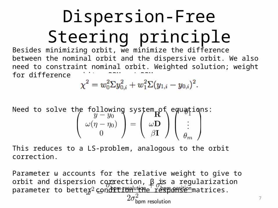
Besides minimizing orbit, we minimize the difference between the nominal orbit and the dispersive orbit. We also need to constraint nominal orbit. Weighted solution; weight for difference orbit ~ BPMacc / BPMres .
Need to solve the following system of equations:
This reduces to a LS-problem, analogous to the orbit correction.
Parameter ω accounts for the relative weight to give to orbit and dispersion correction, β is a regularization parameter to better condition the response matrices.
Dispersion-Free Steering principle

8
History of T-501 (E-211)
• Last year: T-501– We got ~12 hours of effective beam-time: we run SYSID, and
managed to excite orbit bumps
• Last quarter of 2012– the SAREC committee (SLAC Accelerator Research
Experimental Program Committee) accepted our proposal for continuing our tests at SLC-FACET
– We’ve been promoted from T-501 to E-211 (i.e. from test-beam to full featured experiment)
• March 11 – 18, 2013– We got 32+ hours of beam-time

9
Lessons from year 2012Last year we managed to control the orbit, but not the dispersion.
Lessons we learned:• Try to avoid incoming dispersion• Avoid to use N_bpms > N_correctors
Measures we took: We decided to focus on the first half of the linac N_bpms ~ N_correctors We picked the ‘best’ correctors in X/Y, matched by ‘best’ BPMS
in X/Y (i.e. those located at large betas) We run extensive flight-simulations of realistic on-line
conditions before the experiment
10
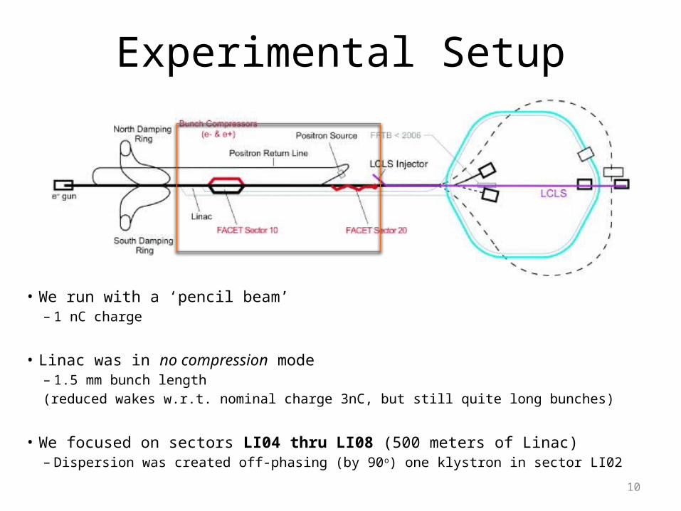
Experimental Setup
• We run with a ‘pencil beam’– 1 nC charge
• Linac was in no compression mode– 1.5 mm bunch length(reduced wakes w.r.t. nominal charge 3nC, but still quite long bunches)
• We focused on sectors LI04 thru LI08 (500 meters of Linac)– Dispersion was created off-phasing (by 90o) one klystron in sector LI02
11
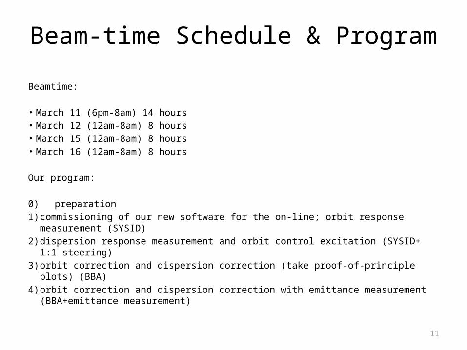
Beam-time Schedule & Program
Beamtime:
• March 11 (6pm-8am) 14 hours• March 12 (12am-8am) 8 hours• March 15 (12am-8am) 8 hours• March 16 (12am-8am) 8 hours
Our program:
0) preparation1) commissioning of our new software for the on-line; orbit response measurement
(SYSID)2) dispersion response measurement and orbit control excitation (SYSID+ 1:1 steering)3) orbit correction and dispersion correction (take proof-of-principle plots) (BBA)4) orbit correction and dispersion correction with emittance measurement
(BBA+emittance measurement)

12
SCP, SLAC Control ProgramSLC, SLAC Linac
facet_getMachine();facet_setMachine();
Preparation
Us trying to steer the beam
Our BBA routines (Matlab)

13Us trying to steer the beam
SCP, SLAC Control ProgramSLC, SLAC LinacPLACET
placet_getMachine();placet_setMachine();
Preparation: Flight Simulator
x
Our BBA routines (Matlab)

14
Effectively, BPM resolution is about 20-30 um (including beam-jitter). We averaged the BPM readings over 100 pulses, reaching an equivalent BPM resolution of:
Sx = 3.3 micromSy = 2.5 microm
Golden Orbit and BPM resolution

15
Results: SysID + orbit control• Focused on Sectors 04 through 08 (500 m of linac!)• Used 52 correctors in total (1h15 acquisition time)• Measured orbit and dispersion (2h30 in total)• Applied Orbit and DFS
Response matrix
We excited a bump in X
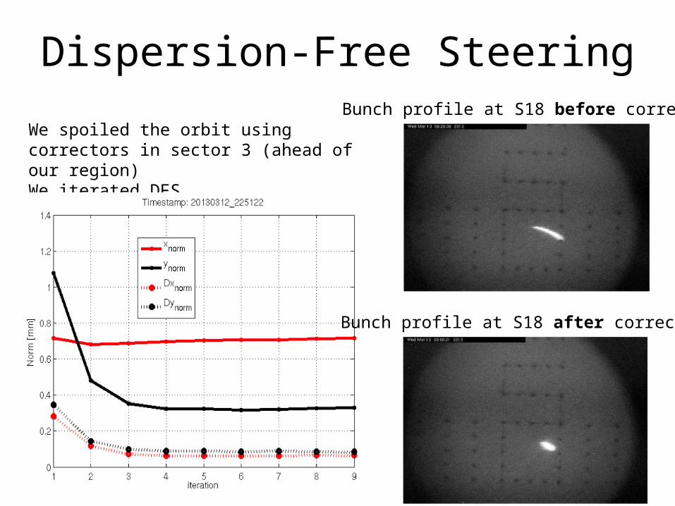
Dispersion-Free SteeringBunch profile at S18 before correction
We spoiled the orbit using correctors in sector 3 (ahead of our region)We iterated DFS
Bunch profile at S18 after correction
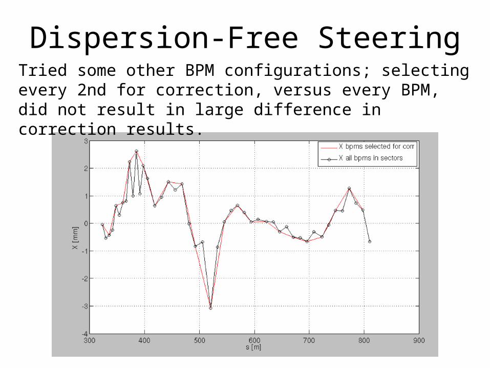
Dispersion-Free SteeringTried some other BPM configurations; selecting every 2nd for correction, versus every BPM, did not result in large difference in correction results.

19Before correction After 3 iterations
Incoming oscillation/dispersion is taken out and flattened; emittance in LI11 and emittance growth significantly reduced.
After 1 iteration
S19 phos, PR185 :
Emittance Growth andDispersion-Free Steering
Emittance at LI11 (iteraton 1)X: 43.2 umY: 27.82 um
Emittance at LI11 (iteration 4)X: 3.71 umY: 0.89 um

20
Conclusions and Future Steps• We succeeded in proving the effectiveness of DFS to correct the emittance,
and in showing the goodness of the SysID algorithms. Completed proof of principle case.
• The responses after one day are still effective -> (no need to re-measure the model); verified by applying same DFS after 1 day -> no significant change in the resulting machine
• Tried various BPM configurations: did not result in large difference in correction results
• Varied parameters w1_w0 and SVD cut, but ended up going back to best parameters we found in simulation (w1_w0 = 10, svd_cut = 0.95)
• Explore new beam-based algorithms to further improve the results

21
Flattening LI11-18• On the spur of our success : We have been asked to correct
the second part of the linac: LI11-18 (900m)
• We managed to flatten orbit and dispersion (gaining a factor 3 in both axes)
• But, the emittance did not show significant improvement– The reason might be that with such a long bunch, the wakefield-
induced emittance growth is larger than the dispersive one– more studies / simulations are needed
• Wake-Free Steering?

22
Wake-Free Steering (WFS)• Measure the system response to a change in the bunch
charge, and use the correctors to minimize it• Preliminary simulation result: