tetrapol specifications; part 1: general network … specifications; part 1: general network design;...
TRANSCRIPT

Publicly PAS 0001-1-3
Available Version: 1.1.1
Specification Date: 15 January 1999
Source: TETRAPOL Forum Work Item No: 0001
Key word: TETRAPOL
TETRAPOL Specifications;Part 1: General Network Design;
Part 3: General Mechanisms
TETRAPOL FORUM
TETRAPOL Secretariat
Postal address: BP 40 78392 Bois d'Arcy CEDEX - FRANCETel.: +33 1 34 60 55 88 - Fax: +33 1 30 45 28 35
Copyright Notification: This is an unpublished work. The copyright vests in TETRAPOL Forum. All rightsreserved.©
The information contained herein is the property of TETRAPOL Forum and no part may be reproduced or usedexcept as authorised by contract or other written permission. The copyright and the foregoing restriction onreproduction and use extend to all media in which the information may be embodied.Tetrapol Forum reserves the right to bring modifications to this document.

Page 2PAS 0001-1-3: Version 1.1.1
1999 - TETRAPOL Forum 15/01/1999This document is the property of TETRAPOL Forum and may not be copied or circulated without permission.
Contents
Foreword .................................................................................................................................................6
1. Scope ..................................................................................................................................................8
2. Normative references...........................................................................................................................8
3. Definitions and abbreviations ...............................................................................................................93.1. Definitions ...............................................................................................................................93.2. Abbreviations ........................................................................................................................13
4. Addressing.........................................................................................................................................144.1. Scope....................................................................................................................................144.2. Individual RFSI Addressing plan............................................................................................15
4.2.1. Types of RFSI addresses.....................................................................................154.2.1.1. Individual Explicit Address ............................................................154.2.1.2. Individual Implicit Address ............................................................154.2.1.3. List Address ..................................................................................15
4.2.2. Address structure.................................................................................................154.2.3. Addressing Plan ..................................................................................................16
4.3. Group Addressing plan..........................................................................................................164.3.1. General ...............................................................................................................164.3.2. Operational Group...............................................................................................164.3.3. OG delivery to the system terminals ....................................................................164.3.4. Different types of OGs.........................................................................................16
4.3.4.1. The nominal OG ...........................................................................174.3.4.2. The national OG ...........................................................................174.3.4.3. The local OG ................................................................................184.3.4.4. The external OG ...........................................................................184.3.4.5. The composed OG........................................................................184.3.4.6. Synopsis .......................................................................................19
4.3.5. OG characteristics ...............................................................................................194.3.6. Triggers for OG distribution .................................................................................19
4.4. PABX addressing plans .........................................................................................................204.5. DATA addressing plans .........................................................................................................204.6. Communication identifiers.....................................................................................................204.7. Terminal equipment serial number ........................................................................................204.8. Country and Network addressing ...........................................................................................20
5. Terminal management .......................................................................................................................205.1. Forwarding service...............................................................................................................20
5.1.1. Scope205.1.2. Description ..........................................................................................................20
5.1.2.1. Invocation .....................................................................................215.1.2.2. Execution of Call Forwarding ........................................................215.1.2.3. Cancelling of Call Forwarding .......................................................22
5.1.3. Interaction with other mechanisms.......................................................................225.1.4. Repeater mode....................................................................................................225.1.5. Direct mode.........................................................................................................225.1.6. Fallback modes ...................................................................................................22
5.2. Terminal enabling / disabling service.....................................................................................225.2.1. Scope225.2.2. Description ..........................................................................................................22
5.2.2.1. Access disable ..............................................................................225.2.2.2. Traffic disable ...............................................................................235.2.2.3. Traffic enable................................................................................235.2.2.4. Service disable .............................................................................23

Page 3PAS 0001-1-3: Version 1.1.1
1999 - TETRAPOL Forum 15/01/1999This document is the property of TETRAPOL Forum and may not be copied or circulated without permission.
6. Mobility management........................................................................................................................ 246.1. Cell selection / cell reselection by roaming ........................................................................... 24
6.1.1. Scope246.1.2. Description ......................................................................................................... 24
6.1.2.1. Definition...................................................................................... 246.1.2.2. Procedures................................................................................... 256.1.2.3. Return to previous cell ................................................................. 256.1.2.4. Cell selection ............................................................................... 256.1.2.5. Cell reselection ............................................................................ 26
6.1.3. Information broadcast by the SwMI..................................................................... 266.1.3.1. Current cell information................................................................ 266.1.3.2. Adjacent cells information ............................................................ 266.1.3.3. Preferred coverage information.................................................... 27
6.1.4. Measures by the RT............................................................................................ 276.1.4.1. Typical radio criteria for cell selection (cell return)........................ 27
6.1.4.1.1. Criteria for leaving a Control Channel............... 276.1.4.1.2. Criteria for leaving a Traffic Channel ................ 27
6.1.4.2. Typical radio measures for Mobility Management......................... 286.1.4.2.1. Radio measures for cell selection (cell return) .. 286.1.4.2.2. Radio measures for cell reselection .................. 28
6.1.5. Special features.................................................................................................. 296.1.5.1. Limited cell selection.................................................................... 296.1.5.2. Applicative criteria........................................................................ 29
6.1.5.2.1. Visiting RT filtering ........................................... 296.1.5.2.2. Country/Network Code...................................... 296.1.5.2.3. Operational/experimental state ......................... 306.1.5.2.4. Preferred COV and preferred BN...................... 306.1.5.2.5. Parent cell or parent RSW................................ 31
6.1.6. Interaction with other services............................................................................. 316.1.7. Fallback modes .................................................................................................. 31
6.1.7.1. BSC-disconnected mode.............................................................. 316.1.7.2. RSWN-disconnected mode .......................................................... 316.1.7.3. Inter-BN disconnected mode ........................................................ 316.1.7.4. RSWN switch-over....................................................................... 32
6.2. Registration and terminal location......................................................................................... 326.2.1. Scope326.2.2. Description ......................................................................................................... 32
6.2.2.1. Definition...................................................................................... 326.2.2.2. Activation..................................................................................... 326.2.2.3. Registration process..................................................................... 336.2.2.4. Home Base Network and Visited Base Network............................ 336.2.2.5. Location information handling in the Network ............................... 336.2.2.6. RT registration states ................................................................... 35
6.2.3. Special features.................................................................................................. 356.2.3.1. Registration classes ..................................................................... 356.2.3.2. Forced registration (informative) .................................................. 356.2.3.3. Full registration ............................................................................ 366.2.3.4. Delayed registration ..................................................................... 366.2.3.5. Activity reporting .......................................................................... 366.2.3.6. Security........................................................................................ 36
6.2.4. Fallback modes .................................................................................................. 366.3. Attach/detach ....................................................................................................................... 37
6.3.1. Scope376.3.2. Description ......................................................................................................... 37
- It is also possible to transmit this information to the Stand AloneDispatch Position.6.3.2.1. Attach activation...................... 38
6.3.2.2. Detach activation ......................................................................... 386.3.2.3. Securisation of the service ........................................................... 38
6.3.3. Information handling ........................................................................................... 386.3.3.1. Use for RT presence detection ..................................................... 38
6.3.3.1.1. Presence of the RT in the Network ................... 386.3.3.1.2. Presence of the RT within a cell ....................... 39
Page 4PAS 0001-1-3: Version 1.1.1
1999 - TETRAPOL Forum 15/01/1999This document is the property of TETRAPOL Forum and may not be copied or circulated without permission.
6.3.3.2. Preferred group communication ....................................................39-6.3.3.3. Active Group communication.......................................................396.3.3.4. Information handling by the Network .............................................39
6.3.4. Interactions with other services and network mechanisms ...................................396.3.4.1. Channel saving .............................................................................396.3.4.2. Private communications................................................................396.3.4.3. Connected messaging...................................................................406.3.4.4. Broadcast messaging....................................................................406.3.4.5. Polling.406.3.4.6. Distribution of states, keys and information to the RTs ..................406.3.4.7. Implicit addressing ........................................................................40
6.3.5. Fallback modes ...................................................................................................406.3.5.1. Inter-BN disconnected mode.........................................................40
6.3.5.1.1. Entry in Inter-BN disconnected mode ................406.3.5.1.2. Exit from Inter-BN disconnected mode ..............40
6.3.5.2. MSW-disconnected mode .............................................................406.3.5.2.1. Entry in MSW-disconnected mode.....................406.3.5.2.2. Exit from MSW-disconnected mode ..................40
6.3.5.3. RSW or BSC-disconnected mode .................................................406.3.5.3.1. Entry in RSW or BSC-disconnected mode.........406.3.5.3.2. Exit from RSW or BSC-disconnected mode ......41
7. Resources management ....................................................................................................................417.1. cell channels management....................................................................................................417.2. resources allocation ..............................................................................................................41
7.2.1. Scope417.2.2. General principles for resources allocation ..........................................................427.2.3. Definition of priorities...........................................................................................42
7.2.3.1. External priorities ..........................................................................427.2.3.1.1. external priorities used for private
communications set up........................427.2.3.1.2. external priorities used for group
communication set up..........................437.2.3.1.3. external priorities used for data communication.437.2.3.1.4. external priorities used for trunked
communication activation ....................447.2.3.2. Internal priorities ...........................................................................44
7.2.4. Network resources allocation rules.......................................................................457.2.4.1. Presentation..................................................................................457.2.4.2. Pre-emption of the allocated resource...........................................467.2.4.3. Queuing for the allocated resource................................................46
7.3. Terminal allocation rules .......................................................................................................477.3.1. Presentation ........................................................................................................477.3.2. Suspended call for a terminal ..............................................................................477.3.3. Queued calls for a terminal..................................................................................477.3.4. Call queuing on resources and on terminals.........................................................47
- allocation of the called terminal.7.4. Channel saving..................................................................477.4.1. Scope477.4.2. Description ..........................................................................................................487.4.3. Information handling............................................................................................48
7.4.3.1. Group subscription mechanism .....................................................497.4.3.2. Voice polling mechanism ..............................................................49
7.4.4. Interaction with other services .............................................................................507.4.4.1. Scanning.......................................................................................507.4.4.2. Late Entry .....................................................................................507.4.4.3. Delayed registration ......................................................................50
7.4.5. Fallback modes ...................................................................................................507.4.5.1. Inter-BN disconnected and RSWN-disconnected mode.................507.4.5.2. RSW-disconnected and BSC-disconnected mode.........................50
7.5. RT wake-up...........................................................................................................................507.6. Data polling...........................................................................................................................51
7.6.1. Scope51

Page 5PAS 0001-1-3: Version 1.1.1
1999 - TETRAPOL Forum 15/01/1999This document is the property of TETRAPOL Forum and may not be copied or circulated without permission.
7.6.2. Description ......................................................................................................... 517.6.2.1. Activation / deactivation ............................................................... 527.6.2.2. Polling principles .......................................................................... 52
7.6.3. Special features.................................................................................................. 527.6.3.1. Radio acknowledgement .............................................................. 527.6.3.2. Network side polling mechanism (informative) ............................. 52
7.6.4. Interaction with other services............................................................................. 537.6.4.1. Interaction with voice services...................................................... 537.6.4.2. Interaction with data services ....................................................... 53
7.6.5. Information handling at application level ............................................................. 537.6.5.1. Service definition ......................................................................... 537.6.5.2. Polling profile ............................................................................... 53
7.6.5.2.1. Polling frequency.............................................. 547.6.5.2.2. Polling answer format ....................................... 54
7.6.6. Description of polling applications (informative) .................................................. 547.6.6.1. Description of an automatic vehicle location (AVL) application
(informative) .................................................................... 547.6.6.2. Description of a measure information collect (informative) ........... 54
7.6.7. Fallback modes .................................................................................................. 557.6.7.1. RSW-disconnected and BSC-disconnected.................................. 557.6.7.2. Network saturation ....................................................................... 55
History .................................................................................................................................................. 56

Page 6PAS 0001-1-3: Version 1.1.1
1999 - TETRAPOL Forum 15/01/1999This document is the property of TETRAPOL Forum and may not be copied or circulated without permission.
Foreword
This document is the Publicly Available Specification (PAS) of the TETRAPOL land mobile radio system,which shall provide digital narrow band voice, messaging, and data services. Its main objective is toprovide specifications dedicated to the more demanding PMR segment: the public safety. Thesespecifications are also applicable to most PMR networks.
This PAS is a multipart document which consists of:
Part 1 General Network Design
Part 2 Radio Air interface
Part 3 Air Interface Protocol
Part 4 Gateway to X.400 MTA
Part 5 Dispatch Centre interface
Part 6 Line Connected Terminal interface
Part 7 Codec
Part 8 Radio conformance tests
Part 9 Air interface protocol conformance tests
Part 10 Inter System Interface
Part 11 Gateway to PABX, ISDN, PDN
Part 12 Network Management Centre interface
Part 13 User Data Terminal to System Terminal interface
Part 14 System Simulator
Part 15 Gateway to External Data Terminal
Part 16 Security
TTR1 Guide to TETRAPOL features
Part 18 Base station to Radioswitch interface
Part 19 Stand Alone Dispatch Position interface

Page 7PAS 0001-1-3: Version 1.1.1
1999 - TETRAPOL Forum 15/01/1999This document is the property of TETRAPOL Forum and may not be copied or circulated without permission.

Page 8PAS 0001-1-3: Version 1.1.1
1999 - TETRAPOL Forum 15/01/1999This document is the property of TETRAPOL Forum and may not be copied or circulated without permission.
1. Scope
This document establishes the TETRAPOL general network design and defines network features thatcomplement the services delivered to the users. It specifies the following features:
- address handling for individuals and groups,- terminal management,- mobility management,
including cell selection at roaming, registration and location management, terminal attach/detachprocedures;
- resources management,including trunking mechanisms, priority management,channel saving and data pollingmechanisms.
Security mechanisms are dealt with in PAS 0001-16-1 [5].
2. Normative references
This PAS incorporates by dated and undated reference, provisions from other applications. Thesenormative references are cited at the appropriate places in the text and the publications are listedhereafter. For dated references, subsequent amendments to or revision of any of these publicationsapply to this PAS only when incorporated in it by amendment or revision. For undated references thelatest edition of publication referred to applies.
[1] PAS 0001-1-1: "TETRAPOL Specifications; General Network Design;Reference Model".
[2] PAS 0001-2: "TETRAPOL Specifications; Radio Air Interface".
[3] PAS 0001-1-2: "TETRAPOL Specifications; General Network Design; Voiceand Data Services in Network and Direct Mode".
[4] PAS 0001-3-1: "TETRAPOL Specifications; Air Interface Protocol; Air InterfaceApplication Protocol".
[5] PAS 0001-3-2: "TETRAPOL Specifications; Air Interface Protocol; Air InterfaceApplication Messages".
[6] PAS 0001-3-3: "TETRAPOL Specifications; Air Interface Protocol; Air InterfaceTransport Protocol".
[7] PAS 0001-10-1: "TETRAPOL Specifications; Inter-system Interface; ISITechnical requirements".
[8] PAS 0001-16-1: "TETRAPOL Specifications; Security; Security mechanismsand Key Management".
[9] TTR 0001-1-2: "TETRAPOL Technical Report; Guide to TETRAPOL features;Reference and Terminology".

Page 9PAS 0001-1-3: Version 1.1.1
1999 - TETRAPOL Forum 15/01/1999This document is the property of TETRAPOL Forum and may not be copied or circulated without permission.
3. Definitions and abbreviations
3.1. Definitions
For the purposes of this PAS, the following definitions apply:
Active Operational Group: an Operational Group is said to be active if there is at least one subscriberbelonging to that Operational Group which is present within the cell.
Base Network (BN): elementary network which is the smallest entity able to operate in normal networkconnected mode and to provide all nominal services and features available in normal network connectedmode. It includes one RSWN and one or more BSs and corresponds to a geogaphical subdivision of anetwork coverage.
Base Network Operational Group (BN OG): (also known as local OG) Operational Group which isdefined at the visited Base Network of its ST members.
Base Station (BS): Station in the TETRAPOL SwMI interfacing the Terminals on a given site.
Base Station Controller (BSC): Base Station interface to the switching network. This subsystemmanages the radio channels, enables the switching network to control the BS and also providesscrambling of the Network voice circuits.
Base Transceiver Station (BTS): Radio subset of the Base Station including the TRX's and thesynchronisation equipment.
Broadcast call: group communication of the "group call" type enabling an authorised user to transmittowards a group of users or towards all users. The users which are called accept the activation order butare not allowed to transmit.
Cell reselection: act of changing the serving cell from a previous cell to a new cell. When the re-selection is successful and possible registration is performed, the RT is said to be attached to the cell.
Cell: operational entity through which terminals can be accessed or localised. There are two types ofcells: radio cells and line connected cells.
Control Channel (CCH): bi-directional BS-RT physical radio channel used for transmitting signalling anddata. Control Channels in a cell include one Main Control Channel (MCCH) and zero, one or severalExtended Control Channels (ECCHs).
Coverage (COV): list of cells all located within one Base Network.
Covered cell: (also known as lower cell) radio cell whose control channel is used by an umbrella cell.
Current cell: cell where the RT is located.
Data Channel (DCH): one or more channels enabled as data channel in a cell to support datatransmission if necessary.
Dispatch Position (DP): The DP is a set of equipment, which enables enhanced dispatchers access toVoice Services. It may be either a SADP or a DC.
Disabled terminal: a (permanently) disabled Terminal can no longer operate in Network connectedmode nor in Direct mode nor in Repeater mode. It can no longer register. It can only be returned tofactory to be enabled again.
Extended Control Channel (ECCH): one or more channels enabled as control channels in a cell tosupplement the Main Control Channel (MCCH).
Page 10PAS 0001-1-3: Version 1.1.1
1999 - TETRAPOL Forum 15/01/1999This document is the property of TETRAPOL Forum and may not be copied or circulated without permission.
External priority: parameter used for allocating the system resources. There are several types ofexternal priorities. External priorities can be set by the user, or by the Operation and MaintenanceCentre, or set to default values.
Fleet: subdivision used for addressing purposes.
Home Location Register (HLR): the location register which stores the reference data base for allTerminals belonging to one BN.
Home Radioswitch Network (HRSWN): RSWN which stores the reference data base for all Terminalsbelonging to one BN. The HRSWN processes the functions of the Home Location Register. The HRSWNis designated by the R field in the subscriber RFSI address.
Internal priority: internal priorities are calculated by the system on the basis of external priorities. Theyare not known to the user which aware only of the consequences of those priorities on the systembehaviour.
Isolated cell: cell where the Base Station is isolated from the rest of the infrastructure.
Line Access Base Station (LABS): network interface to Line Connected Terminals and to SADPs, alsoknown as Line Connection Interface Unit (LCIU).
Line connected cell: a line connected cell is the coverage of a Line Access Base Station.
Line Connected Terminal (LCT): System Terminal (ST) locally or remotely connected to the Systemthrough a physical wired connection line. The System interface to LCTs is a Line Access Base Station.
Location Area: an area within radio coverage of a Base Station or a group of Base Stations in which aMobile Station may move freely without updating the location register.
Location register: functional unit in which the location information is stored.
Location registration: the updating of a location register by exchange of user identity between theSwMI and the RT.
Main Control Channel (MCCH): Control Channel with a System constant downlink scramblingparameter. There shall always be one and only one Main Control Channel per cell.
Migration: process of moving RT attachment from one Location Area to another in a different System.
Network mode: operational mode where the RT is under coverage and listening to the Network (the RThas a serving cell). The Network is the system fixed infrastructure.
Non-active Operational Group: an Operational Group is said to be non-active if there is no subscriberbelonging to that Operational Group which is present within the cell.
Open channel: type of communication including multisite open channels, broadcast calls andemergency open channels. Multisite open channels may be used on quasi-transmission trunked ormessage trunked traffic channels mode. Broadcast calls and emergency open channels are used onmessage trunked traffic channels mode.
Operational Group (OG): an Operational Group (OG) is a group of subscribers all of whom share acertain right to participate in a Group Communication or to set-up a Multi-site Open Channel.
Organization: Federative entity that shall gather set of terminals (ST, TWP, SADP, ...) using dedicatedor shared resources, and having management rights and partitioned or not partitioned services access.
Operator: responsible person or entity for the operation of a network.

Page 11PAS 0001-1-3: Version 1.1.1
1999 - TETRAPOL Forum 15/01/1999This document is the property of TETRAPOL Forum and may not be copied or circulated without permission.
Parent cell: cell where a subscriber is required to register. The corresponding procedure whereby theuser can force a particular cell to be selected is called "cell forcing by the user". The correspondingprocedure whereby the Network can force a particular cell to be selected is called "cell forcing by theNetwork".
Parent RSW: RSW with which a subscriber is required to register.
Preferred Base Network (PBN): Base Network whose cells should preferably be chosen for cellselection or cell reselection.
Preferred Coverage (PCOV): set of the cells within coverage of a user-chosen preferred groupcommunication.
Previous cell: cell where the RT effected its last registration.
Radio Base Station (RBS): Radio subset of the TETRAPOL SwMI interfacing the Radio Terminals.
Radio cell: a cell is the geographical area corresponding to the radio electrical coverage of one BaseStation (monosite cell) or of a group of Base Stations synchronised to emit an identical signal (simulcastcell).
Radio Terminal (RT): System Terminal connected to the infrastructure by means of a radio link alsoknown as Mobile Termination Unit or MTU.
Registration class: parameter enabling the network to control the RT registration flow at the cell level.The RT registration class is an RT's own parameter which determines its privileges for registration. TheSwMI registration class is broadcast in a cell and determines the required level for registration in the cell.
Registration: act of becoming an active and recognised Network user by exchange with the SwMI ofuser identity.
Roaming: process of changing RT attachment from one Location Area to another within a TETRAPOLSystem.
Serving cell: (also known as current cell) cell which has been selected by cell return, cell selection orcell reselection. If the terminal is registered the serving cell is the visited cell. If the terminal is pendingregistration it is the cell where temporary traffic is allowed.
Simulcast cell: (also known as macrocell) coverage area of several BTSs controlled by the same BSCand which transmit or receive the same communication or signalling on the same physical radiochannels.
Stand Alone Dispatch Position (SADP): a Stand Alone Dispatch Position is an isolated operatorposition providing access to dispatch and management functions.
Subfleet: operational subdivision of a fleet (used for addressing purposes).
Suspended terminal: a suspended terminal continues to register. It cannot be used for communicationneither in Network connected mode nor in Repeater nor Direct mode. A Terminal ManagementCommand (at the OMC) is used to enable it again.
SwMI Operational Group (SwMI OG), also known as Network OG: Operational Group which is definedat the Home Base Network of its member STs.
System Terminal (ST): service access reference point provided to the user by the System. Systemterminals are Radio Terminals (RTs) and Line Connected Terminals (LCTs).
Traffic Channel (TCH): bi-directional BS - RT physical radio channel used for transmitting voice or data.

Page 12PAS 0001-1-3: Version 1.1.1
1999 - TETRAPOL Forum 15/01/1999This document is the property of TETRAPOL Forum and may not be copied or circulated without permission.
Umbrella cell: radio cell whose Base Stations are collocated with the Base Stations of several radio cellsknown as covered cells. All Control Channels for the umbrella cell are provided by the covered cells, theumbrella cell having no Control Channel of its own.
Visited cell: cell where the terminal is registered.
Visited Location Register (VLR): the location register where all relevant parameters concerning aMobile Station are stored as long as the RT is in a location area controlled by this register.
Visited Radioswitch (VRSW): a Terminal's Visited RSW is the RSW where the Terminal is registered. Itmay be the Terminal's Home RSW.
Visited Radioswitch Network (VRSWN): a Terminal's Visited RSWN is the RSWN of the BN where theTerminal is registered. It may be the Terminal's Home RSWN.
Visitor terminal: terminal whose Home BN and Visited BN are different.
Page 13PAS 0001-1-3: Version 1.1.1
1999 - TETRAPOL Forum 15/01/1999This document is the property of TETRAPOL Forum and may not be copied or circulated without permission.
3.2. Abbreviations
For the purposes of this PAS, the following abbreviations apply:
A/I Air InterfaceBN Base NetworkBNOG Base Network Operational GroupBS Base StationBSC Base Station ControllerBTS Base Transceiver StationCC Country CodeCCH Control CHannelCGI Collective Group IdentifierCNA Coded Nature of AddressCOV COVerageCRP Connection Reference PointDACH Dynamic Access CHannelDB DataBaseDC Dispatch CenterDCH Data ChannelDM Direct ModeDM/NM Direct Mode/Network MonitoringDP Dispatch PositionECCH Extended Control ChannelEDT External Data TerminalFBM FallBack ModeFER Frame Erasure RateGPS Global Positioning SystemGSSI Group Short Subscriber IdentityHLR Home Location RegisterHRSW Home RadioSWitchH/V Home/VisitedIRI Inter base network InterfaceISSI Individual SubScriber IdentityISI InteR System InterfaceLABS Line Access Base StationLCT Line Connected TerminalMCCH Main Control CHannelMMI Man-Machine InterfaceMOCH Multisite Open CHannelMRI Mobile Random IdentityMS Mobile StationNC Network CodeNMC Network Management CentreNPI Numbering Plan IdentifierOG Operational GroupOMC Operation and Maintenance CentrePBN Preferred Base NetworkPABX Private Automatic Branch eXchangePAS Publicly Available SpecificationPMR Private Mobile RadiocommunicationsPSTN Public Switched Telecommunications NetworkPTT Push-To-TalkQSIG Signalling at Q reference pointRACH Random Access CHannelRBS Radio Base StationRFSI Base Network - Fleet - Subfleet - Individual addressRi Reference point index iRP RePeaterRSW RadioSWitchRSWN RadioSWitch NetworkRT Radio Terminal

Page 14PAS 0001-1-3: Version 1.1.1
1999 - TETRAPOL Forum 15/01/1999This document is the property of TETRAPOL Forum and may not be copied or circulated without permission.
SA Secondary AddressSADP Stand Alone Dispatch PositionSCH Signalling CHannelSCS Secured Communication SupportSF Short Functional addressSN Short NumberSSI Short Subscriber IdentityST System TerminalSwMI Switching and Management InfrastructureTC Trunk CodeTCH Traffic CHannelTON Type of Short NumberTRX Transmitter / ReceiverTTI Temporary Terminal IdentifierUA User AgentUDT User Data TerminalUSI Universal Subscriber IdentityVCH Voice ChannelVLR Visited Location RegisterVRSW Visited RadioSWitchVRSWN Visited RadioSWitch Network
4. Addressing
4.1. Scope
This subclause defines the TETRAPOL addressing plans, that shall be used for voice and datacommunications and for subscriber management.
Within a system identified with a country code and a network code, the subscriber addresses areorganised into the following categories:
- Individual RFSI addresses;- Group addresses (operational groups);
- ITU-T X.400 addresses;- Internet IP addresses;
- PABX sub-addresses from an external addressing plan;-
Voice group communications identities are organised in the following categories:
- MOCH identifiers;- Talkgroup and group call identifiers, including group and coverage identities.
A terminal equipment shall be identified with a serial number.
4.2. Individual RFSI Addressing plan
4.2.1. Types of RFSI addresses
4.2.1.1. Individual Explicit Address
Each system terminal or access gate shall be identified by an individual explicit RFSI address whichshall be unique in a system. System terminals include both radio and line connected terminals. Accessgates include the service access reference points to external equipments such as PABX, SADP, DC.
An individual explicit address shall be used for the following purposes:

Page 15PAS 0001-1-3: Version 1.1.1
1999 - TETRAPOL Forum 15/01/1999This document is the property of TETRAPOL Forum and may not be copied or circulated without permission.
- as a basis for the numbering plan for private communications;- as an identification of the calling party or of the called party in a private communication; as a
talking party identifier in a private or group voice communication;- for susbcriber management and security management, e.g.the association of a subscriber to a
system terminal.
4.2.1.2. Individual Implicit Address
An implicit address shall designate one system terminal among a predefined set of system terminals.
When an implicit address is used in a private call or in a data communication, the network shall replacethe implicit address by one explicit address, by dynamically selecting one of the system terminals amongthe predefined set of terminals associated with the implicit address.
Terminals that are associated to an implicit address shall have the following properties:
For any given implicit address, there may beLine Connected Terminals (LCTs) and stationary RadioTerminals (RTs):
- all the terminals (LCT or stationary RT) shall be connected to the same RSW;- if they are RTs, they shall all be registered in the same Cell;
The implicit address and the associated explicit addresses shall belong to the same BN..
An explicit address can belong to several implicit addresses.
An implicit address shall be interpreted in the RSW which controls the BS or the Line Access BaseStations involved.
4.2.1.3. List Address
A List Address shall designate a set of individual addresses. The interpretation of a list address shallconsist in replacing it by the complete set of addresses in the definition set. The interpretation of a listaddress shall be carried out in the Network.
A list address may designate STs registered in any BN in the System.There is a maximum number ofaddresses in a list address.
A list address shall only be expanded by the directory entity from the BN in which it was defined.
The rules defining the conditions for use shall be described with the specification for each function.
4.2.2. Address structure
Within a SwMI, A TETRAPOL address shall be in the RFSI format, it shall be comprised of four fields:
- R: [3] decimal digits designating a Base Network (BN) in the SwMI;- F: [1] decimal digit designating a fleet belonging to the user organization;- S: [2 or 1] decimal digits designating a subfleet (functional entity) in that fleet;- I: [3 or 4] decimal digits designating a terminal in the case of an individual explicit address.
Table 1: RFSI format A
36 bitsR1 R2 R3 F S1 S2 I1 I2 I3
Table 2: RFSI format B
36 bitsR1 R2 R3 F S1 I1 I2 I3 I4
Page 16PAS 0001-1-3: Version 1.1.1
1999 - TETRAPOL Forum 15/01/1999This document is the property of TETRAPOL Forum and may not be copied or circulated without permission.
4.2.3. Addressing Plan
R designates a Base Network. Part of the R addressing space shall be reserved for special purposes.
F designates a Fleet.
If R designates the Base Network and F designates a Fleet, then the S field shall designate a Subfleet(functional entity) in that fleet.
If an RFS sequence designates a subfleet internal to a fleet based in a BN, then the value of the I fieldshall designate a System Terminal which belongs to that subfleet or is used for specific purposes.
4.3. Group Addressing plan
4.3.1. General
A group is identified by a 4-digit number (OG):
- which belongs to one organization,- which designates all the participants of a collective application (group communication or data
communication);-The participants of voice group communications and the recipients of group delivery of data are definedwith one or several group addresses.
4.3.2. Operational Group
An Operational Group (OG) is a set of STs sharing the same rights to set-up, release or participate inGroup Communications.
An organization can "own" several OGs. These OGs can be created, modified or suppressed within thatowner organization.
4.3.3. OG delivery to the system terminals
The network transmits to the ST:
- the type of the OG;- the identity of the OG;-
4.3.4. Different types of OGs
There are several types and subtypes of OGs:
The network distributes a maximum number of OGs per ST (typically 10). Each ST shall accept at leastthoses distributed OGs.
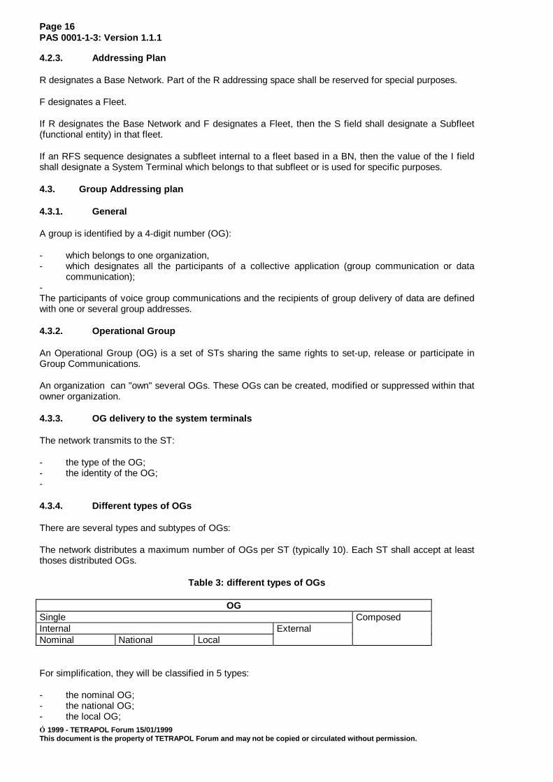
Table 3: different types of OGs
OGSingle ComposedInternal ExternalNominal National Local
For simplification, they will be classified in 5 types:
- the nominal OG;- the national OG;- the local OG;

Page 17PAS 0001-1-3: Version 1.1.1
1999 - TETRAPOL Forum 15/01/1999This document is the property of TETRAPOL Forum and may not be copied or circulated without permission.
- the external OG;- the composed OG.
The type of OG is either defined by the manager at the OG creation, or implicit depending on the OGnumbering plan.
4.3.4.1. The nominal OG
Each subscriber own one and only one nominal OG which is communicated to it by configuration (it isone of the attributes of the RT which is known from the RT, the OMC and the system in general).
This OG can not be delivered to the RT over the air.
It is valid over the entire system.
4.3.4.2. The national OG
A national OG can be used on the entire system.
Whether a subscriber belongs to a national group or not is only memorized in its home networkdatabase.
A national OG shall not be created if it is already created as local in another BN.
When visiting a BN, a subscriber may use its national OGs in the same manner as a Base Networksubscriber.
The national OGs of a subscriber are delivered to the RT over the air each time it is modified.
BN n°1 BN n°2 BN n°3
set of participants in BN n°1
set of participants in BN n°2
set ofparticipantsin BN n°3
national OG n° i
Figure 1: the national OG
The national OG can be used to participate in any group communication (voice or data).
4.3.4.3. The local OG
A local OG is only significant within the BN where it was defined.
Each OMC may define its local OGs, the participants can belong to any BN.
BN n°1 BN n°2 BN n°3
set of theparticipantsin all BNs
set of theparticipants
set of theparticipants
local OG n° j local OG n° j local OG n° j
in all BNs in all BNs
Figure 1: the local OG
Page 18PAS 0001-1-3: Version 1.1.1
1999 - TETRAPOL Forum 15/01/1999This document is the property of TETRAPOL Forum and may not be copied or circulated without permission.
Whether a subscriber belongs to a group (identified by a local OG) is only memorized in the visited BNdatabase.
The local OGs are distributed over the air each time one of them is modified or each time one of thementers the BN.
The RT "erases" the local OGs from a BN each time it exits the BN.
4.3.4.4. The external OG
The external OG is an OG whose characteristics are managed at the OMC, but the composition ismanaged by an external tool.
The external OG is identical to the national OG, with 2 differences:
- The external OG is not distributed to the RT over the air, but by an external means to theTETRAPOL system.
- The TETRAPOL network is not aware, for each OG, of the list of the subscribers to the group.
NOTE: The maximum number of OGs owned by an RT is limited, the network ensures that control forall types of OGs except for the external OG.
In the case of external OGs, the RT ensures this control by himself, the RT always accepts anOG delivery over the air by the network.
In the other case where the total number of OGs it owns is superior to the maximum numberof authorised RTs: the RT does not take into account the excess of external OGs.
4.3.4.5. The composed OG
The composed OG is not known to the OMC and to the subscriber.
It is a group identifier used to define the union of several groups identified by single OGs participating toa same group communication.
This facility is used for the following communications:
- the multisite open channel (which owns several participation OGs)The association is only temporary (the time when the communication is set-up) and is indicated[composed OG = set of single OGs] to the RTs by means of a periodical delivery.
When an RT notices that a composed OG has appeared and that it owns at least one of the single OGs,it takes into account this composed OG which is then substituted to the single OG which it then replaces.
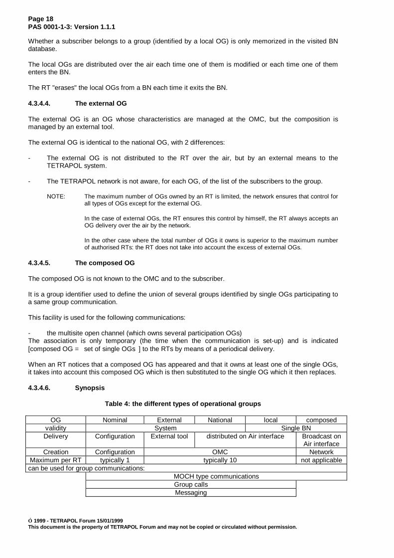
4.3.4.6. Synopsis
Table 4: the different types of operational groups
OG Nominal External National local composedvalidity System Single BNDelivery Configuration External tool distributed on Air interface Broadcast on
Air interfaceCreation Configuration OMC Network
Maximum per RT typically 1 typically 10 not applicablecan be used for group communications:
MOCH type communicationsGroup callsMessaging

Page 19PAS 0001-1-3: Version 1.1.1
1999 - TETRAPOL Forum 15/01/1999This document is the property of TETRAPOL Forum and may not be copied or circulated without permission.
4.3.5. OG characteristics
The OG is coded on 4 MCDU digits (0000 to 4095).
The OG characteristics are:
the "proprietary" organization deducted from the OG number by the system,
its encryption capacity deducted from the encryption capacity of the "proprietary" organization,
the type of OG: either defined by the operator (nominal, national, local or external), or implicit(composed),
the scope of the OG:- private: the OG shall only be used by the proprietary organization to define group
communications,- public: the OG may be used by any organization to define group communications.
the composition of the OG:
The information is obtained under the form of a list of participation RFSI which may belong to differentorganization or different BN.
4.3.6. Triggers for OG distribution
Operational group distribution to a terminal is dynamically performed
- when a group definition is modified and affects the membership of the terminal in the group
- or when a terminal enters a base network, for delivering local OG.
Whatever the number of modified OGs is, the Network always delivers all OGs of a same type.
The Network shall interrupt the OG delivery when the RT is:
- inactive;- or unreachable.
In case of delivery failure, the Network attempts to distribute these OGs to the RT:
- periodically;- immediately after a successful transaction with the RT.
4.4. PABX addressing plans
When addressing an external subscriber through a PABX gateway for a private communication, asubaddress may be provided in the external PABX addressing plan.
4.5. DATA addressing plans
ITU-T X.400 addressing plan may be used to access an external X.400 network via an X.400 MTAgateway for TETRAPOL messaging services.
Internet IP addresses are used for TCP-UDP/IP data services between user data terminals or between auser data terminal and an IP gateway.
4.6. Communication identifiers
A group communication is composed by one or some participation OGs (every type of OG exceptcomposed OG) and operational attributes, that are:
Page 20PAS 0001-1-3: Version 1.1.1
1999 - TETRAPOL Forum 15/01/1999This document is the property of TETRAPOL Forum and may not be copied or circulated without permission.
- group trunking priority,- associated shared coverage,- partition number : deducted from the "proprietary" organization,- the encryption mode : clear or encrypted,- the type of encryption key: NNK, RNK, ONNK, ORNK,- the activation state of the channel saving: enabled or out of order,- the definition limit: mono or multi base network.
In case of multi base network, the list of slaves base networks and the master base network of thecommunication.
Multi-site open channel are addressed with a specific adressing plan, that allows 254 MOCH addressesper base network. A Talkgroup and a group call is identified with a group identifier (OG). There may beup to 255 coverage identifiers per base network.
4.7. Terminal equipment serial number
Each terminal equipment shall be uniquely identified with an 8 digit serial number allocated by theequipment manufacturer. This serial number shall be used for security features.
4.8. Country and Network addressing
A country code and a network code shall be allocated to the network and to the system terminals, so thehome system of a terminal requesting registration be compared to the visited system, thus enabling toprevent registration from foreign terminals.
5. Terminal management
5.1. Forwarding service
5.1.1. Scope
This clause indicates how the call forwarding supplementary service is performed.
5.1.2. Description
This service is activated upon request from a terminal to be unconditionnally diverted to another terminal(radio or line connected).
The would-be forwarded terminal designates a host address where all incoming private calls and dataservices shall be re-routed.
5.1.2.1. Invocation
Terminals requesting Call Forwarding shall be registered and in Network Mode (normal Networkconnected mode, Inter-BN disconnected FBM or RSW disconnected FBM), otherwise the CallForwarding command shall be rejected.
Terminals requesting Call Forwarding shall not be already forwarded.
Terminals requesting Call Forwarding shall be on Stand-by on the CCH or in an Open Channelcommunication.
Terminals shall forward calls even when in a visited BN.
The Call Forwarding Set-up command parameter shall be the host address.
The host address shall be a terminal's individual explicit or implicit address. Otherwise the commandshall be rejected:
If it is an explicit address, the host address shall correspond to a terminal which may be called with itsexplicit address (right available in the terminal profile).

Page 21PAS 0001-1-3: Version 1.1.1
1999 - TETRAPOL Forum 15/01/1999This document is the property of TETRAPOL Forum and may not be copied or circulated without permission.
If it is an implicit address, this implicit address shall exist.
The System shall not check if the host address itself is already forwarded. This shall be checked whenthe Call Forwarding is executed.
5.1.2.2. Execution of Call Forwarding
Call Forwarding shall be executed when the forwarded individual address is used as a recipient for aPrivate Call or a Data Call in Network connected mode for interpersonnal messaging.
The call handling procedure shall replace the forwarded address by the host address. The handlingprocedure shall proceed with the host address. The System shall locate the host address.
If the host address is also forwarded, the transaction shall fail.
If the host address does not satisfy the transaction's specific conditions, the transaction shall fail.
If the home RSW of the host terminal is not accessible, the transaction shall fail.

Page 22PAS 0001-1-3: Version 1.1.1
1999 - TETRAPOL Forum 15/01/1999This document is the property of TETRAPOL Forum and may not be copied or circulated without permission.
5.1.2.3. Cancelling of Call Forwarding
Call Forwarding shall be cancelled only by the terminal whose address is forwarded.
This Terminal shall be registered in Network connected mode. It may be registered either in its home BNor in another BN.
5.1.3. Interaction with other mechanisms
In Network connected mode, a Forwarded Terminal can cancel Call Forwarding, accept an EmergencyCall, make outgoing calls and participate in Group Communications under the same conditions as a non-forwarded Terminal.
A Forwarded Terminal cannot set-up nor release a Multisite Open Channel.
5.1.4. Repeater mode
A forwarded terminal can operate in reapeater mode.
5.1.5. Direct mode
A forwarded terminal can operate in direct mode.
5.1.6. Fallback modes
A Forwarded Terminal can operate in fallback modes:
- Inter-BN disconnected mode,- MSW disconnected mode,- RSW disconnected FBM;- BS disconnected FBM.5.2. Terminal enabling / disabling service
5.2.1. Scope
The RT management application shall support the following additional network features:
- access disable shall allow the SwMI to permanently bar RT access to the network;- traffic enable / disable shall allow the SwMI to temporarily disable RT user activity;- service bar shall allow the SwMI to report that the RT has been disabled by the OMC of its
home BN.
The purpose of the present subclause is to describe the enable/disable general principles andmechanisms. The corresponding protocol can be found in PAS 0001-3-2 [5]. Due to the general nature ofthis subclause, if any discrepancy occurs between this subclause and PAS 0001-3-2 [5] then PAS 0001-3-2 [5] shall take precedence.
5.2.2. Description
5.2.2.1. Access disable
Access disable shall allow the SwMI to permanently bar RT access to the network. a (permanently)disabled Terminal can no longer operate in Network connected mode nor in Direct mode nor in Repeatermode. It can no longer register. It can only be returned to the factory or the maintenance centre to beenabled again.
On receipt of the request, if the serial number contained in the request matches the RT's serial number,the RT shall accept the order with all the effects it has on sensitive terminal data. After a certain delay itshall send an acknowledgement to the SwMI then shut down.

Page 23PAS 0001-1-3: Version 1.1.1
1999 - TETRAPOL Forum 15/01/1999This document is the property of TETRAPOL Forum and may not be copied or circulated without permission.
If the serial number contained in the request does not match the RT's own serial number, the RT shallsend an acknowledgement to the SwMI and ignore the request.
If the RT is on a traffic channel, the SwMI shall force the RT to return to the control channel then executethe bar application transaction.
If the application transaction is not successfully executed, the SwMI shall initiate a timed process:
- if the RT is no longer present for the SwMI, the SwMI shall initiate an application transaction to baraccess immediately after the next RT registration transaction;
- if the RT sets up a contact with the SwMI for another application transaction, the SwMI shall rejectthe transaction then execute the application transaction to bar RT access.
5.2.2.2. Traffic disable
Traffic disable shall allow the SwMI to temporarily disable RT user activity.
If the serial number contained in the request matches the RT's serial number, the RT shall accept theorder with all the effects it has on the terminal then send an acknowledgement to the SwMI.
If the serial number contained in the request does not match the RT's own serial number, the RT shallsend an acknowledgement to the SwMI and ignore the request.
If the RT is on a traffic channel, the SwMI shall force the RT to return to the control channel then executethe disable application transaction.
If the application transaction is not successfully executed, the SwMI shall initiate a timed process:
- if the RT is no longer present for the SwMI, the SwMI shall initiate an application transaction todisable traffic immediately after the next RT registration transaction;
- if the RT sets up a contact with the SwMI for another application transaction, the SwMI shall rejectthe transaction, then execute the application transaction to disable RT traffic.
5.2.2.3. Traffic enable
Traffic enable shall allow the SwMI to enable RT user activity.
The RT is not on a traffic channel since it is traffic disabled. The RT shall execute the applicationtransaction to enable RT traffic.
If the application transaction is not successfully executed, the SwMI shall initiate a timed process.
If the RT is no longer present for the SwMI, the SwMI shall initiate an application transaction to enabletraffic immediately after the next RT registration transaction.
5.2.2.4. Service disable
Service disable shall allow the SwMI to report that the RT has been disabled by the OMC of itshome BN.
If the serial number contained in the request matches the RT's serial number, the RT shall react as itwould on receipt of a registration refusal.
If the serial number contained in the request does not match the RT's own serial number, the RT shallsend an acknowledgement to the SwMI and ignore the request.
If the RT is no longer present for the SwMI, the SwMI shall initiate an application transaction to disableservice immediately after the next RT registration transaction.
If the RT has set up a contact with the SwMI for another application transaction, the SwMI shall reject thetransaction, then execute the application transaction to bar RT service.

Page 24PAS 0001-1-3: Version 1.1.1
1999 - TETRAPOL Forum 15/01/1999This document is the property of TETRAPOL Forum and may not be copied or circulated without permission.
6. Mobility management
The following mechanisms are supported for the mobility of system terminals:
- cell selection / cell reselection;- registration and terminal location;- attach / detach.
6.1. Cell selection / cell reselection by roaming
6.1.1. Scope
The present subclause deals with Mobility Management and the roaming function for System Terminals(STs). As such, it is primarily applicable to Radio Terminals (RTs), but it could also apply to other STs.
Terminal roaming procedures use the following information:
- information broadcast by the Network;- information available to the RT through personalisation or Man-Machine Interface (MMI);- information measured by the RT.
This subclause further details the information broadcast by the Network.
Considering the large range of PMR projects and the specificity of the needs of each category of users,the criteria, algorithms and parameters are not specified as such. The scenarios (criteria, algorithms andparameter values) shall be the same for all terminals belonging to one network. It is the operatorresponsibility to ensure that the scenario implemented in the terminal is compatible with thatimplemented in the Network.
6.1.2. Description
6.1.2.1. Definition
For registration purposes and to be an active participant in private calls and group communications anRT needs to select a cell. When the RT is listening to a cell Control Channel it is said to be camped onthe cell. After the cell has been chosen and possible registration has been performed, the RT is said tobe attached to the cell.
Roaming is the process of moving RT attachment from one location area to another within a Network forwhich the user has a valid registration. A location area is an area within radio coverage of a Base Stationor of a group of Base Stations in which a Mobile Station may move freely without updating the locationregister.
Migration of a terminal between two different Networks can also be taken into account. For moreinformation on theses aspects, refer to PAS 0001-10-1 [6].

Page 25PAS 0001-1-3: Version 1.1.1
1999 - TETRAPOL Forum 15/01/1999This document is the property of TETRAPOL Forum and may not be copied or circulated without permission.
6.1.2.2. Procedures
The different procedures for attaching a terminal to a cell are presented in Figure 1:
- Return to previous cell: returning to the previously known cell;- cell selection: finding the best available cell according to radio criteria and applicative criteria;- cell reselection: switching from the current cell to an adjacent cell if better radio criteria and/or
better applicative criteria are met.
Direct Mode
Return to previous cell
Power on
Direct mode
Network Mode
Successful
Cell selection
Failure
Power off
Success
Cell reselection
Cell reselection
Reselection of a cell
Exit from
Cell selection
criteria metcriteria met
Power off
Isolated cell
FBM
Selection ofan isolated cell
Cell selectioncriteria met
Failure
returnPower on
(first registrationprocedure)
(the terminal has beenregistered in the Network)
NOTE 1: Direct Mode/Network monitoring (dual watch) is a sub-state of Network Mode, Direct Mode, Isolated cell FBM.
Failure(Out of coverage)
Independent
digital repeatermode
Figure 2: Roaming procedures
6.1.2.3. Return to previous cell
The RT shall first try to select the same cell in which it was registered beforehand (cell return). If the RTis not registered yet in any cell or if an event has happened such that the previous cell cannot bereselected, the RT shall invoke the cell selection procedure.
6.1.2.4. Cell selection
The cell selection procedure consists in measuring either all system channels or channels of the adjacentcells only. Within the best cells, the RT shall choose one, not necessarily the strongest, which satisfiesappropriate applicative criteria such as:
- network and country;- operational/experimental state;- Preferred COV/BN;- parent cell/RSW.
Page 26PAS 0001-1-3: Version 1.1.1
1999 - TETRAPOL Forum 15/01/1999This document is the property of TETRAPOL Forum and may not be copied or circulated without permission.
6.1.2.5. Cell reselection
For reselecting the best available cell as far as received quality of the radio signal is concerned, the RTshall activate immediately and on a permanent basis a cell reselection procedure. This procedureconsists in measuring the available cells adjacent to its current cell which satisfy appropriate applicativecriteria. If one of those cells is better according to a cell threshold radio criteria, the RT shall migrate tothis cell.
6.1.3. Information broadcast by the SwMI
6.1.3.1. Current cell information
The SwMI shall periodically broadcast information on the current cell and system (seeD_SYSTEM_INFO message in PAS 0001-3-2 [4]). The following information shall be included:
- network and cell identification (unambiguous identification of the country, the network in thecountry, the BN in the network, the cell in the BN, and the location area);
- cell set-up information (cell configuration information, radio parameters, registration class, localtime and uplink scrambling).
6.1.3.2. Adjacent cells information
When moving into a cell, the RT shall acquire the list of adjacent cells (see D_NEIGHBOURING_CELLmessage in PAS 0001-3-2 [4]). This list shall be broadcast at regular intervals on the Control Channel.This list shall contain NR01 cells at the most.
This message contains the reselection parameters which are for each adjacent cell:
- the cell channel number (see note 1);- the cell threshold parameter (see note 2);- indicators stating:
- whether the cell is experimental or operational (see note 3);- whether the cell is within the same location area as the serving cell (see note 4);- whether the cell is in the same BN as the serving cell (see note 5).
NOTE 1: The CHANNEL_ID parameter is defined in PAS 0001-3-2 [5], CHANNEL_ID informationelement.
NOTE 2: The RXLEV_ACCESS parameter is defined in PAS 0001-3-2 [5], ADJACENT_PARAMinformation element.
NOTE 3: The EXP parameter is defined in PAS 0001-3-2 [5], ADJACENT_PARAM information element.
NOTE 4: The LOC parameter is defined in PAS 0001-3-2 [5], ADJACENT_PARAM information element.
NOTE 5: The BN parameter is defined in PAS 0001-3-2 [5], ADJACENT_PARAM information element.
For each cell, the identities of the adjacent cells are entered at the OMC.
Cell reselection parameters of a cell shall be transmitted to the HRSWN of each of its adjacent cells.This information shall be transmitted:
- at regular intervals;- if one of the reselection parameters is modified.
Page 27PAS 0001-1-3: Version 1.1.1
1999 - TETRAPOL Forum 15/01/1999This document is the property of TETRAPOL Forum and may not be copied or circulated without permission.
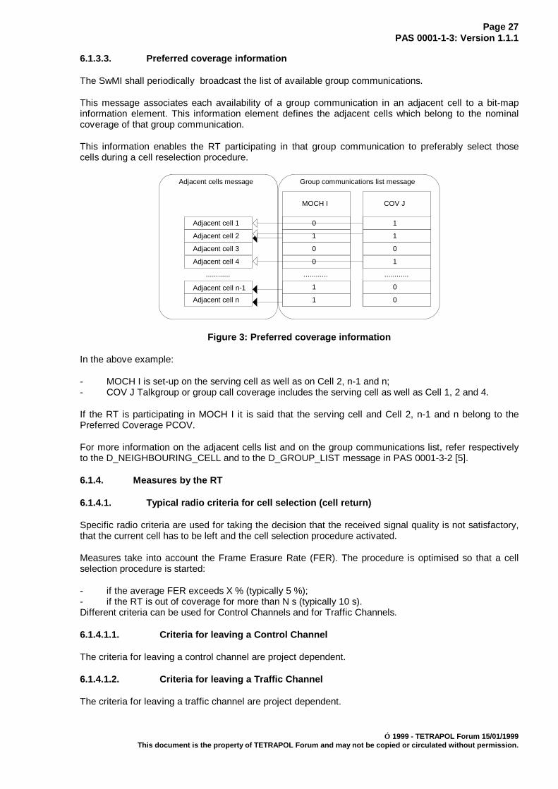
6.1.3.3. Preferred coverage information
The SwMI shall periodically broadcast the list of available group communications.
This message associates each availability of a group communication in an adjacent cell to a bit-mapinformation element. This information element defines the adjacent cells which belong to the nominalcoverage of that group communication.
This information enables the RT participating in that group communication to preferably select thosecells during a cell reselection procedure.
Adjacent cell 1
Adjacent cell 2
Adjacent cell 3
Adjacent cell 4
Adjacent cell n-1
Adjacent cell n
............
MOCH I
............
0
1
0
0
1
1
COV J
............
0
1
0
0
1
1
Group communications list messageAdjacent cells message
Figure 3: Preferred coverage information
In the above example:
- MOCH I is set-up on the serving cell as well as on Cell 2, n-1 and n;- COV J Talkgroup or group call coverage includes the serving cell as well as Cell 1, 2 and 4.
If the RT is participating in MOCH I it is said that the serving cell and Cell 2, n-1 and n belong to thePreferred Coverage PCOV.
For more information on the adjacent cells list and on the group communications list, refer respectivelyto the D_NEIGHBOURING_CELL and to the D_GROUP_LIST message in PAS 0001-3-2 [5].
6.1.4. Measures by the RT
6.1.4.1. Typical radio criteria for cell selection (cell return)
Specific radio criteria are used for taking the decision that the received signal quality is not satisfactory,that the current cell has to be left and the cell selection procedure activated.
Measures take into account the Frame Erasure Rate (FER). The procedure is optimised so that a cellselection procedure is started:
- if the average FER exceeds X % (typically 5 %);- if the RT is out of coverage for more than N s (typically 10 s).Different criteria can be used for Control Channels and for Traffic Channels.
6.1.4.1.1. Criteria for leaving a Control Channel
The criteria for leaving a control channel are project dependent.
6.1.4.1.2. Criteria for leaving a Traffic Channel
The criteria for leaving a traffic channel are project dependent.
Page 28PAS 0001-1-3: Version 1.1.1
1999 - TETRAPOL Forum 15/01/1999This document is the property of TETRAPOL Forum and may not be copied or circulated without permission.
6.1.4.2. Typical radio measures for Mobility Management
Channel measure for cell selection and cell reselection are based on the following principles:
- during cell selection, all network services are suspended to find the best cells of the researchdomain;
- on the contrary, radio measures for cell reselection do not interfere with other services. Theseradio measures are based on a frame stealing mechanism; since relative levels can varysignificantly, an average criteria has to be taken into account over a sufficient period of time inorder to have accurate measurements for cell reselection;
- measures take into account the level of the signal received.
6.1.4.2.1. Radio measures for cell selection (cell return)
The RT measures the power of the signal received on each channel in the research domain (see note 1)and arranges the channels per decreasing power order. It then draws up a limited list of the first best NR05channels with a received power superior to SR01 dBm (see note 2).
NOTE 1: The research domain includes all potential control channels in the system, for complete cellselection, and, for limited cell selection, all potential control channels in the serving andadjacent cells.
NOTE 2: In the case of limited cell selection the number of channels to be measured may be inferior toNR05.
6.1.4.2.2. Radio measures for cell reselection
The RT periodically measures the power of the received signal (RXLEV) on the MCCH channels for itscell and for each adjacent cell .
Measures are based on a frame stealing mechanism. 20-ms time intervals are stolen in each 4 ssuperframe.
The RT calculates a mean value of the received signal (RXLEV_MEAN) for each cell in the followingconditions:
- to be significant the mean is calculated from at least N measures, NR02 ≤ N ≤ NR04;- every measure older than TR02 seconds is not taken into account for the mean value calculation;- the time interval between two measures of the same channel is at least DR03 seconds.
For each mean value calculation the RT deducts the threshold result for this cell (CELL_THRESHOLD):
CELL_THRESHOLD = RXLEV_MEAN - RXLEV_ACCESS (see note)
NOTE: The RXLEV_ACCESS parameter is broadcast in the D_ADJACENT_CELLS message. Fordetailed coding of this parameter, see PAS 0001-3-2 [5].
For each modification of the adjacent cells message and of the adjacent cells restricted list, the RTreinitialises the process.
If the RT sees that since TR04 seconds the CELL_THRESHOLD result of one of the adjacent cells is morethan SR02 dB to that of its current cell, the RT migrates to that adjacent cell.
There shall be a TR05 maximum interval of time before the RT decides to change cells and during whichthe cell reselection condition is true.
6.1.5. Special features
6.1.5.1. Limited cell selection
There are several versions of cell selection algorithms, one of them limited in its radio channels researchdomain, the other taking into account the complete research domain.

Page 29PAS 0001-1-3: Version 1.1.1
1999 - TETRAPOL Forum 15/01/1999This document is the property of TETRAPOL Forum and may not be copied or circulated without permission.
Complete cell selection involves measuring all potential control channels in the system.
Limited cell selection involves measuring the serving and adjacent control channels only. If the RT hassufficient information on the adjacent cells, the list of Control Channels for the adjacent cells should berestricted:
- to the adjacent cells which belong to the Preferred coverage (PCOV) if the RT has any;- otherwise, to the adjacent cells which belong to the Preferred Base Network (PBN) if the RT has
any.
6.1.5.2. Applicative criteria
Several applicative criteria may be taken into account for cell selection and cell reselection. They are oftwo different types:
- absolute criteria:- Country Code (CC)/Network Code (NC);- operational/experimental cell and RT state;- visiting RT filtering;
- relative criteria:- preferred COV (PCOV);- preferred cells list (known from the RT);- preferred Base Network;- status of the cell (isolated or not).
Absolute criteria shall be fulfilled for selecting a cell; relative criteria may be used to select a cell againstanother cell.
6.1.5.2.1. Visiting RT filtering
The RT whose home base network is different from their currently visited base network may be filteredout of the visited base network.
These RT whose HLR is not in the base network shall recognise that they are considering a cell in a basenetwork different from their home base network by comparing the R field of their individual explicit RFSIaddress and the BN_ID parameter broadcast by the cell of that base network in D_SYSTEM_INFOTSDU [5].
This criterion may be used when a base network is put into service in order to forbid access of the cellsof the BN to the visiting Rts.
This capability is a cell characteristics and it shall be controlled by the network management withoutrequiring cell reinitialisation.
Each cell broadcasts information for the current cell via the D_SYSTEM_INFO TSDU [5] on thebroadcast channel of the air interface.
6.1.5.2.2. Country/Network Code
Each cell of a system shall continually broadcast the following system information parameters on the AirInterface :
- a Country Code (CC);- a Network Code (NC) identifying the Network within the Country.
A Radio Terminal (RT) shall also have the knowledge of its own country code and network code.:
The country and network codes are absolute criteria for selecting a cell, so that a RT shall be able to selectthe cell and register in the network identified with (CC,NC) only if it is authorized in thatnetwork.

Page 30PAS 0001-1-3: Version 1.1.1
1999 - TETRAPOL Forum 15/01/1999This document is the property of TETRAPOL Forum and may not be copied or circulated without permission.
NOTE: CC and NC are the COUNTRY_CODE and NETWORK parameters defined inPAS 0001-3-2 [5] COUNTRY_CODE and SYSTEM_ID information elements inD_SYSTEM_INFO TSDU [5].
6.1.5.2.3. Operational/experimental state
The operational/experimental state of the RT and of the candidate cells is a criteria which is used forsetting a new cell within an already operational network.
The operational/experimental state of a cell is chosen at the OMC. This does not imply cellreinitialisation. This information is broadcast periodically via the SYS_INFO message on the broadcastchannel.
In the list of neighbouring cells which is broadcast periodically, the network indicates the"experimental/operational" status for each of them.
The operational/experimental state of an RT is a personalisation choice.
The rule for granting RT access to operational and experimental cells is as indicated on Figure 4:
- STs with an "experimental" state are given access to all cells;- STs with an "operational" state are given access to operational cells only.
An RT is a home RT if the "R" field of the cell (via the SYS_INFO message on the broadcast channel)and its own state are identical.
Only the "home" RTs may register in a cell where visitor RTs are filtered.
experimental cell
operational celloperational ST
experimental ST
Figure 4: Operational/experimental cell access
6.1.5.2.4. Preferred COV and preferred BN
The RT should remain as much as possible within its Preferred Coverage (PCOV) and Preferred BaseNetwork (PBN).
To ensure this, cells within PCOV and/or PBN are preferred for cell selection and cell reselection. PCOVtakes precedence over PBN.
An RT may have a declared Preferred Coverage or no declared Preferred Coverage.
An RT always has a declared Preferred Base Network. When no PBN is specified by the user, the defaultvalue is specified. The default value is its Home BN.
6.1.5.2.5. Parent cell or parent RSW
It is possible for the user to choose a particular cell or RSW through an MMI command and force the RTto remain within that "parent" cell or RSW.
A parent cell is a cell where a subscriber is required to register. The corresponding procedure wherebythe user can force a particular cell to be selected is called "cell forcing by the user".

Page 31PAS 0001-1-3: Version 1.1.1
1999 - TETRAPOL Forum 15/01/1999This document is the property of TETRAPOL Forum and may not be copied or circulated without permission.
When a subscriber has a parent RSW, it is required to register within a cell controlled by that RSW.
It is also possible for the Network to force the RT to remain within a particular cell or RSW and force theRT to remain within that "parent" cell or RSW.
The corresponding procedure whereby the Network can force a particular cell to be selected is called"cell forcing by the Network".
6.1.6. Interaction with other services
The RT does not change cells during a push-to-talk depression.
During cell selection activation, all network services are suspended to find the best cells of the researchdomain.
On the contrary, radio measures for cell reselection do not interfere with other services. These radiomeasures are based on a frame stealing mechanism.
6.1.7. Fallback modes
BTS 1 BTS 2
BSC 1 BSC 2
RSWN 1 RSWN 2
BSC-disconnected
RSWN-disconnected
Inter-BN disconnected
Duplex switch-over
Cell 1 Cell 2
Figure 5: Fallback modes
6.1.7.1. BSC-disconnected mode
- The list of adjacent cells is not received in Cell 1;- The reselection parameters of Cell 1 are not received in its adjacent cells.
6.1.7.2. RSWN-disconnected mode
- The last message received with the list of adjacent cells and the reselection parameters isbroadcast in Cell 1;
- The reselection parameters of Cell 1 are not received in its adjacent cells.
6.1.7.3. Inter-BN disconnected mode
- The list of adjacent cells is broadcast in Cell 1 with the last reselection parameters receivedfor Cell 2;
- The list of adjacent cells is broadcast in Cell 2 with the last reselection parameters received for Cell 1.
On the other hand, information concerning the cells within the BN is not affected within the BN.
6.1.7.4. RSWN switch-over
- RSWN 2 polls the RSWs controlling the adjacent cells of Cell 2 and asks for retransmission oftheir reselection parameters.
Page 32PAS 0001-1-3: Version 1.1.1
1999 - TETRAPOL Forum 15/01/1999This document is the property of TETRAPOL Forum and may not be copied or circulated without permission.
6.2. Registration and terminal location
6.2.1. Scope
The System shall enable a System Terminal (ST) to register in the network The registration applicationshall be used for RT location and identification if required.
The registration procedure may be preceded by a cell selection procedure.
6.2.2. Description
6.2.2.1. Definition
Registration is the act of becoming an active and recognised Network user by exchange with the SwMI ofuser identity. It is an automatic process whereby the System Terminal informs the Network it has enteredunder coverage or that it has moved within the Network coverage.
Registration is necessary to access Network services, that is, to communicate in Network connectedmode (NM, Inter-BN disconnected FBM and Location Register disconnected FBMs) and to be located.
Registration is not mandated during network fallback modes, as long as the terminal has been previouslyregistered at least once. Registration is not needed in repeater mode and in direct mode.
6.2.2.2. Activation
A Terminal shall register:
- when it is powered on (when it is first put into service or when it is put into service again afterreparation);
- if it has been inactive for too long, its Temporary Terminal Identifier (TTI) is no longer attributed(switched off, out of coverage, generally "not reachable by the network");
- when the Terminal leaves a previous cell for a new cell which does not belong to the samelocation area;
- after a service disabling transaction (see note);- if the uplink scrambling parameter is not the same as that which was in service when the RT
registered.
NOTE: The service disabling procedure is described in subclause 4.3: "Enable / disable" of thisSpecification.
A Terminal can register if its state is In Service and Access Enabled.
A terminal shall not register:
- if the registration class in the current cell is higher than the registration class of the terminal- before random timer between two consecutive requests has expired.
A Terminal which remains registered in a cell for a long time shall communicate with the Network atregular intervals, either when it handles calls or using automatic service transaction designed for thispurpose. A voice call signal, a message transmission or an individual service transaction are allconsidered as communications by the Network.
If a Terminal has not communicated with the Network for too long, this Terminal shall re-register when itnext requests a communication with the Network, even if it has not changed location area.
The Terminal in Direct Mode is seen from the Network point of view as an inactive terminal.
Page 33PAS 0001-1-3: Version 1.1.1
1999 - TETRAPOL Forum 15/01/1999This document is the property of TETRAPOL Forum and may not be copied or circulated without permission.
The RT shall not be allowed to register in the following cases:
- the cell is operating in BSC-disconnected mode;- the cell is operating in RSW-disconnected mode;- its registration class is strictly below the class broadcast in the cell, except in the case of "forced
registration";- the delayed registration timer is set.
6.2.2.3. Registration process
Three registration procedures may be supported:
- normal registration- full registration, when the terminal enters into operational mode or when its internaly saved data
are lost.- forced registration in a cell
6.2.2.4. Home Base Network and Visited Base Network
In order for a terminal to register, it shall have been declared in a given Base Network which is said to bethe Home Base Network for this Terminal. The Terminal individual parameters are stored in the LocationRegister of the Home Base Network. This Location Register is said to be the Home Location Register forthe Terminal.
The Base Network in which the Terminal is registered is said to be the Visited Base Network for theTerminal and its Location Register is said to be Visited Location Register. When the Terminal isregistered in its Home Base Network, the Home Base Network and the Visited Base Network areidentical. The VLR under which coverage the Terminal is located is said to be Visited Base Network.
An LCT or SADP shall always register under the LABS to which it is connected.
6.2.2.5. Location information handling in the Network
In order to locate a Terminal it is necessary to know:
- the identity of its Visited Base Network (= identity of its VLR);- the identity of its Visited Radio Switch;- the identity of the Location Area controlled by the VLR under which the Terminal is located.This information is provided as follows:
- the identity of the Visited Location Register is known to the Home Location Register;- the identity of the Visited Radio Switch is known to the Visited Location Register;- the identity of the Location Area controlled by this VRSW under which the Terminal is located is
known to the Visited Radio Switch.
The Terminal is characterised by an individual address. When a terminal is designated by its individualaddress it is possible to know its HLR, then following the sequence above, its exact location.

Page 34PAS 0001-1-3: Version 1.1.1
1999 - TETRAPOL Forum 15/01/1999This document is the property of TETRAPOL Forum and may not be copied or circulated without permission.
VLR
VRSW
VLR
VRSW
HLR
Initial location area
registration
registrationerrasure
errasure
registration
attributes
attributes
VRSWN VRSWN
HRSWN
Arrival location area
Figure 6: The RT has changed BN or asked for "full registration"
HRSW
VLR
VRSW
HLR
Initial location area Arrival location area
registrationerrasure
registration
attributes
HRSWN
VRSWN
VRSWN
Figure 7: The RT changes its Radioswitch inside the BN
VLR
VRSW
HLR
Initial location area Arrival location area
registration
HRSWN VRSWN
Figure 8: The VRSW manages alone the changes of the terminal between the BSs
Page 35PAS 0001-1-3: Version 1.1.1
1999 - TETRAPOL Forum 15/01/1999This document is the property of TETRAPOL Forum and may not be copied or circulated without permission.
6.2.2.6. RT registration states
A Terminal may have the following Registration states:- "non-registered";- "pending registration";- "registered".
A "non-registered" Terminal or "pending registration" becomes "registered" after cell registrationsucceeds.
A "registered" terminal which changes Cell shall have the "pending registration" state.
A Terminal "pending registration" becomes "non-registered" if it has not succeeded in registering within agiven period of time.
For more details on RT registration states, see PAS 001-3-1 [4].NOTE: RT participation into groupcommunication pending registration is an optional RT features.
6.2.3. Special features
6.2.3.1. Registration classes
Registration classes give terminals different priorities for access to registration and consequently tonetwork services. The way classes are generated in the Network is such as to avoid phenomena of rapidsaturation of the Base Stations.
The registration procedure uses 2 types of registration classes:
- the SwMI registration class (SwMI_RC) which is broadcast in the cell and determines the minimumrequired RT registration class. It can not be less than the minimum registration class in the cell;
- the RT registration class (RT_RC) which is an RT's own parameter and determines its privilegesfor registration.
Before requesting any registration, the RT shall compare its own registration class with the SwMIregistration class:
- RT_RC ≥ SwMI_RC: RT is allowed registration;- RT_RC < SwMI_RC: the RT can not register, however, it can participate to group communications.
The RT shall not take its registration class into account and shall re-evaluate its registration rights in thefollowing cases:
- the RT is in an emergency situation initiated by the user;- the RT is in a situation of forced registration notified by the Network.
6.2.3.2. Forced registration (informative)
The SwMI may try to force the RT to register through a forced registration procedure.
Forced registration is an operation which is automatically decided by the Network. It is enabled inexceptional circumstances, its purpose is to force a non-registered RT to ignore the "registration class"parameter value broadcast in the cell and to reassess its registration rights.
This request only applies to a non-registered RT. It only is effected when there is a request:
- access disabling;- service disabling;- traffic disabling;- RT tracing.

Page 36PAS 0001-1-3: Version 1.1.1
1999 - TETRAPOL Forum 15/01/1999This document is the property of TETRAPOL Forum and may not be copied or circulated without permission.
6.2.3.3. Full registration
In the following circumstances:
- RT back-up information loss;- first time the terminal is put into service;- modification of the configuration parameters.
the RT shall perform a specific registration sequence: "full registration". This procedure shall always behandled by the HRSW.
The RT shall request full registration within the Network by resetting the registration counters.
The registration process uses a registration sequence containing three counters which are used forregistration purposes by the Network:
- C_CR: a "full registration" counter generated by the Network,counts [modulo 256] the number of registration requests submitted to the HRSW;
- C_BN: a "BN" counter generated by the terminalcounts [modulo 256] the number of BN changes where a terminal registers. It is reset in case of"full registration";
- C_RSW: an "RSW" counter generated by the terminalcounts [modulo 256] the number of RSW changes where the terminal registers. It is reset in caseof "full registration".
6.2.3.4. Delayed registration
The entrance (and the exit) into saturation is progressive in order to authorise registration:
- for RTs with a "high registration class";- for RTs in an emergency situation;- for RTs on Network request (forced registration in order to disable it for example).
RTs which are not allowed registration have access to group communications.
6.2.3.5. Activity reporting
This role of this feature is to maintain a minimum dialogue with the Network in order to keep the RT inthe "active" state as seen by the Network.
6.2.3.6. Security
The registration shall include an identification. The registration can be followed by a mutualauthentication between the terminal and the network.
Security mechanisms such as authentication and encryption are dealt with in PAS 0001-16 [7].
6.2.4. Fallback modes
When a cell changes to RSW-disconnected mode or BSC-disconnected mode this information isbroadcast on the CCH.
The location tables of the RSW which is associated to the cell are marked as "not available". Thelocations at VLR and HLR level are not affected but are subject to modification when terminals register inother cells.
When the cell recovers from isolated state this information is broadcast on the control channel. When itinforms the terminals that they have to re-register, the network changes the uplink scrambling parameterof the Control channel.
The restart of an RSW is handled as a restart from each of its cells.

Page 37PAS 0001-1-3: Version 1.1.1
1999 - TETRAPOL Forum 15/01/1999This document is the property of TETRAPOL Forum and may not be copied or circulated without permission.
The failure of an RSW is seen from the BN as a dialogue failure. The RSW location tables of the givenLocation Area are not to be used but are not erased. They shall evolve with the terminal registration inother RSWs.
6.3. Attach/detach
6.3.1. Scope
This subclause describes the Attach / detach mechanism which is implemented in the System Terminaland which is used by the ST to keep the Network informed about its communication state.
This information is useful for saving Network resources, especially radio resources, by not involving RTsin transactions when they are unable to participate (for example the attach / detach mechanism can beused to implement channel saving).
Contrary to the registration procedure, the attach/detach mechanism is a fast, one-way process and doesnot provide any information concerning the location (only the terminal characteristics).
Attach / detach is a network mechanism which can be configured on a per project basis. Informationindicating whether attach is mandatory is broadcast over the Air Interface under all the cells of thenetwork.(see Note).
NOTE: For more information, refer to the D_SYSTEM_INFO message, CELL_CONFIG informationelement defined in PAS 0001-3-2 [5].
6.3.2. Description
Attach / detach is a mechanism whereby the System Terminal keeps the Network informed about:
- its own status vector (traffic disabled or not, forwarded or not, fix or mobile);- its own status versus DATA: type of polling, state or the UDT-ST link,- its preferred group communication: this identifier is:
- the user-choosen group communication (operationnal group, or multi-site open channel) ifthe terminal is in talkgroup or in multi-site open channel,
- a group call mode terminal has no preferred group communication,- in case of priority scanning, the preferred group communication is the priority group
communication,- in case of scanning, there is no preferred group communication.
These informations are used mainly for the following purposes:
- detailed state of the ST- it is possible not to involve the ST in voice or messaging transactions when it is off;- it is possible not to involve the ST in messaging transactions when it is unable to handle
messages (for example, the ST is not connected to a UDT);- information is not broadcast to the ST when it is powered off;- the STs which are powered off or unable to transmit the relevant information are not subject
to polling;
- channel saving: when the terminal is present, using the preferred group communication identifier,the network is able to know if this group communication is active within a cell and is able to usethis information for its resource management.
- It is also possible to transmit this information to the Stand Alone DispatchPosition.6.3.2.1. Attach activation
The ST may activate the attach function and may send the above information in the following cases:

Page 38PAS 0001-1-3: Version 1.1.1
1999 - TETRAPOL Forum 15/01/1999This document is the property of TETRAPOL Forum and may not be copied or circulated without permission.
- the ST is powered on (except if another transaction is necessary (registration, activityreporting,...));
- the informations transmitted by the network after a registration concerning the ST data state andthe preferred group communication are different from the one memorized in the ST,
- the ST returns to network mode after it has been in direct mode or in independent digital repeatermode;
- the ST is a candidate to a first or different group communication than the one which had beenselected previously,
- at each preferred group communication removal: the RT shall transmit an attach messagecontaining the non-significant group communication identifier (see PAS 0001-3-2 [5]);
- at each modification of the DATA status (modification of polling profile, modification of the UDT-ST link state...).
6.3.2.2. Detach activation
The RT may activate the detach mechanism in the following cases:
- the RT is powered off;- the RT is about to switch to direct mode (without Network monitoring) or is about to switch to
independent digital repeater mode.
This mechanism consists in sending a message containing the cause information.
In case of access failure (no reply from the SwMI), the RT can retry and then may proceed and eitherturn the power off or switch to direct mode.
6.3.2.3. Securisation of the service
Both attach and detach mechanisms are acknowledged on the Air interface (see PAS 0001-3-1 [4] andPAS 0001-3-2 [5]).
If the attach acknowledgement is not received by the ST, it shall:
- either activate a cell selection procedure and repeat the attach message afterward,
- or choose a better neighbouring cell thanks to the cell reselection procedure, register itself andrepeat the attach message if the informations transmitted by the network afterward are differentfrom the one of the ST.
The detach is never repeated even if the detach acknowledgement is not received by the ST.
6.3.3. Information handling
6.3.3.1. Use for RT presence detection
6.3.3.1.1. Presence of the RT in the Network
The attach / detach function can be used to detect the ST's presence in the Network.
The RT is declared to be present in the Network in the following cases:
- ST registration;- reception by the Network of an attach message;- transaction in connected mode.
The RT is declared to be unreachable in the following case:
- reception of a detach message.

Page 39PAS 0001-1-3: Version 1.1.1
1999 - TETRAPOL Forum 15/01/1999This document is the property of TETRAPOL Forum and may not be copied or circulated without permission.
6.3.3.1.2. Presence of the RT within a cell
The attach / detach function can be used to detect the RT's presence within a cell.
The RT is declared to be present within the cell in the following case:
- ST registration.- reception by the Network of an attach message;- transaction in connected mode
The ST is declared to be not present from the cell in the following cases:
- RT declared to be unreachable from the Network;- RT activity time-out;- RT registration within another cell.
6.3.3.2. Preferred group communication
The preferred group communication is used for the channel saving and for the ST supervision at theSADP.
The ST is declared to have a preferred group communication within a cell if the ST is present within thecell, and the ST has sent an attach message with that preferred group communication.
The ST is declared to have not a given preferred group communication within a cell if the ST is notpresent within that cell, or on reception of an attach message with another preferred groupcommunication.
-6.3.3.3. Active Group communication
A Group communication is said to be active if there is at least one subscriber declared with thatpreferred Group communication within that cell.
A Group communication is said to be non-active if there is no subscriber declared to have that preferredGroup communication within that cell.
6.3.3.4. Information handling by the Network
The information "RT present" and these contained in the state vector shall be memorised in the RTdatabases of the RSW which are backed-up.
The "preferred group communication" field is present in the RT database in the RSW only. It contains the"preferred OG" information or the "preferred MOCH" information.
The "active OG" information is obtained from the "preferred OG" information and from the identity of thecell where the RT is registered.
6.3.4. Interactions with other services and network mechanisms
6.3.4.1. Channel saving
When there is an activation, the Traffic Channel is not taken for a group communication unless the groupis active. In this case, the paging mechanism is implemented in the BSC.
6.3.4.2. Private communications
The Network shall reject the requests for communications towards STs which are not present.
Page 40PAS 0001-1-3: Version 1.1.1
1999 - TETRAPOL Forum 15/01/1999This document is the property of TETRAPOL Forum and may not be copied or circulated without permission.
6.3.4.3. Connected messaging
The messages are not transmitted towards STs which are unreachable or which are unable to handle themessages.
6.3.4.4. Broadcast messaging
The individual addressed messages are not transmitted towards STs which are unreachable.
6.3.4.5. Polling.
Polling is suppressed for STs which are unreachable or for STs which are unable to answer to polling.
6.3.4.6. Distribution of states, keys and information to the RTs
The distribution is suspended for STs which are unreachable. It is resumed as soon as the ST manifestsits activity. The distribution priority is not increased and respects the present rules.
6.3.4.7. Implicit addressing
The STs which are unreachbleare removed from the list of the STs to which the Network presents thecall.
6.3.5. Fallback modes
6.3.5.1. Inter-BN disconnected mode
6.3.5.1.1. Entry in Inter-BN disconnected mode
When a visitor ST registers in a "Inter-BN-disconnected" mode, it is "locally" registered. It is present. Thestate vector is provided by the ST to the Network via the registration procedure. If the informationsconcerning the ST state versus data or the preferred group communication are not the same as the ST,then it is updated via the attach message.
6.3.5.1.2. Exit from Inter-BN disconnected mode
Databases are resynchronised. The "ST present" and the state vector information are managed in thesame way as the other dynamic information. The "preferred group communication" information is presentin the RSW only.
6.3.5.2. MSW-disconnected mode
6.3.5.2.1. Entry in MSW-disconnected mode
When an RT registers in the MSW-disconnected mode, it is "locally" registered. It is present. The statevector is provided to the Network by the RT via the registration process. If the informations concerningthe ST state versus data or the preferred group communication are not the same as the ST, then it isupdated the attach message.
6.3.5.2.2. Exit from MSW-disconnected mode
Databases are resynchronised. The "RT present" and the state vector information are managed in thesame way as the other dynamic information. The "preferred group communication" information is presentin the RSW only.
6.3.5.3. RSW or BSC-disconnected mode
6.3.5.3.1. Entry in RSW or BSC-disconnected mode
The ST does not transmit attach/detach messages.
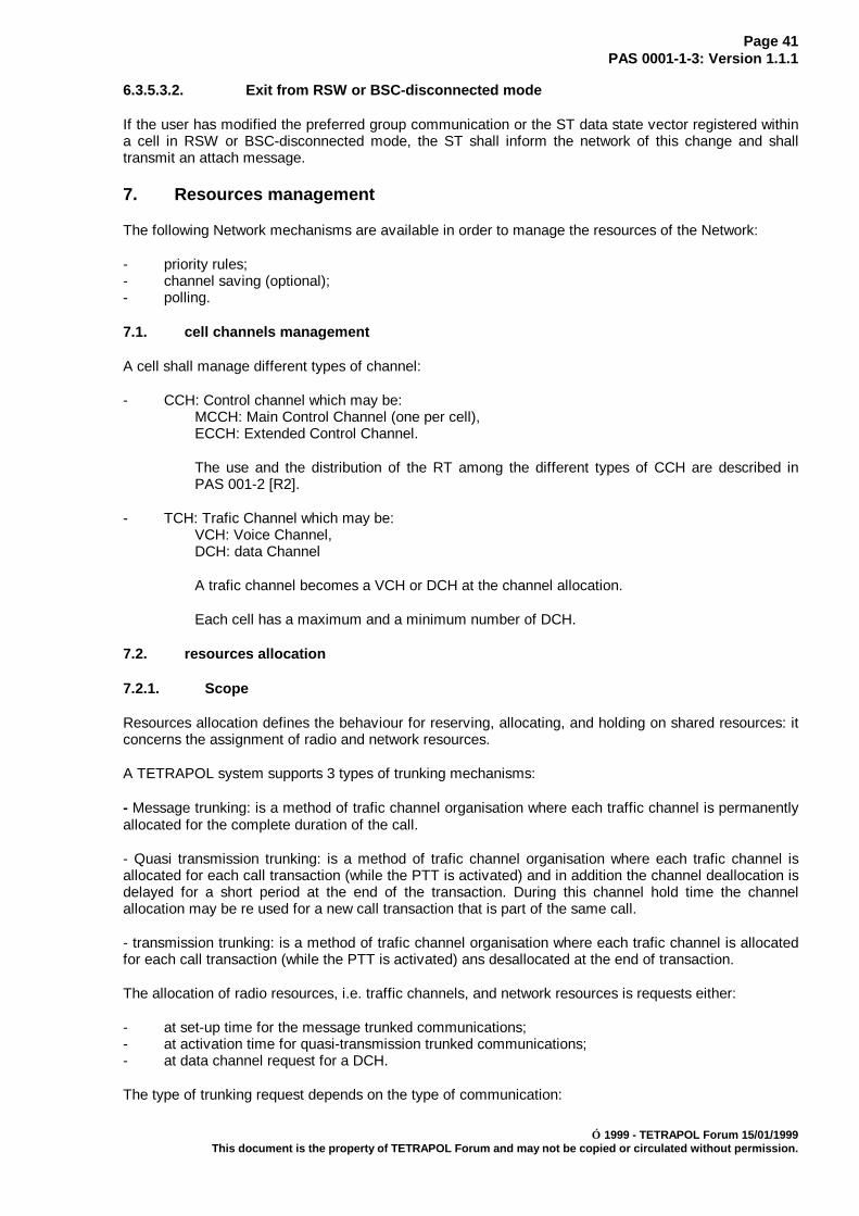
Page 41PAS 0001-1-3: Version 1.1.1
1999 - TETRAPOL Forum 15/01/1999This document is the property of TETRAPOL Forum and may not be copied or circulated without permission.
6.3.5.3.2. Exit from RSW or BSC-disconnected mode
If the user has modified the preferred group communication or the ST data state vector registered withina cell in RSW or BSC-disconnected mode, the ST shall inform the network of this change and shalltransmit an attach message.
7. Resources management
The following Network mechanisms are available in order to manage the resources of the Network:
- priority rules;- channel saving (optional);- polling.
7.1. cell channels management
A cell shall manage different types of channel:
- CCH: Control channel which may be:MCCH: Main Control Channel (one per cell),ECCH: Extended Control Channel.
The use and the distribution of the RT among the different types of CCH are described inPAS 001-2 [R2].
- TCH: Trafic Channel which may be:VCH: Voice Channel,DCH: data Channel
A trafic channel becomes a VCH or DCH at the channel allocation.
Each cell has a maximum and a minimum number of DCH.
7.2. resources allocation
7.2.1. Scope
Resources allocation defines the behaviour for reserving, allocating, and holding on shared resources: itconcerns the assignment of radio and network resources.
A TETRAPOL system supports 3 types of trunking mechanisms:
- Message trunking: is a method of trafic channel organisation where each traffic channel is permanentlyallocated for the complete duration of the call.
- Quasi transmission trunking: is a method of trafic channel organisation where each trafic channel isallocated for each call transaction (while the PTT is activated) and in addition the channel deallocation isdelayed for a short period at the end of the transaction. During this channel hold time the channelallocation may be re used for a new call transaction that is part of the same call.
- transmission trunking: is a method of trafic channel organisation where each trafic channel is allocatedfor each call transaction (while the PTT is activated) ans desallocated at the end of transaction.
The allocation of radio resources, i.e. traffic channels, and network resources is requests either:
- at set-up time for the message trunked communications;- at activation time for quasi-transmission trunked communications;- at data channel request for a DCH.
The type of trunking request depends on the type of communication:

Page 42PAS 0001-1-3: Version 1.1.1
1999 - TETRAPOL Forum 15/01/1999This document is the property of TETRAPOL Forum and may not be copied or circulated without permission.
Table 5: allocation of TCH
radio resource (traffic channel)set-up activation DCH
Private communications 3Message trunked MOCH 3
QTT Trunked MOCH 3group call 3
High rate data messaging 3NOTE: a DCH may contain several high data rate messaging transactions.
The sharing of resources is managed by the system so as to control the access to the subscriberresources when the system is heavily loaded. It depends on 2 criteria:
- priority rules: they depend at the same time on the organisation of the network subscribers, of theuser choice and on the system parameters;
- trafic channel guaranty rules: they ensure, independently from the priority rules, that eachorganization is garanteed access to a minimal number of radio resources.
7.2.2. General principles for resources allocation
When part of the resources or all of the resources requested are not available, the system preempts orwaits for some resources which are alaready allocated to be released.
It uses 3 types of "internal" priorities:
- the internal allocation priority;- the internal retention priority;- the internal preemption priority,
which are themselves deducted from the type of communication and some external priorities:
7.2.3. Definition of priorities
7.2.3.1. External priorities
7.2.3.1.1. external priorities used for private communications set up
- external allocation priority: it can take 3 values corresponding to the following levels: ROUTINE,FLASH or EMERGENCY.this priority is choosen by the user and sent to the network at the call set up request.
- user priority: provided to the radio terminal at its personnalisation and sent to the network at thecall set up request.
It may take 3 different values:
Table 6: User priority
VALUESMaximal priority 2Intermediate priority 1Minimal priority 0
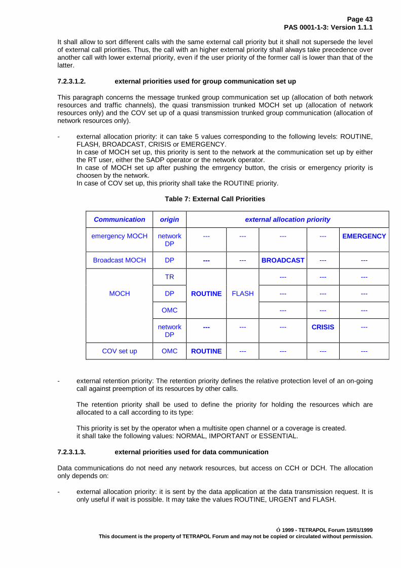
Page 43PAS 0001-1-3: Version 1.1.1
1999 - TETRAPOL Forum 15/01/1999This document is the property of TETRAPOL Forum and may not be copied or circulated without permission.
It shall allow to sort different calls with the same external call priority but it shall not supersede the levelof external call priorities. Thus, the call with an higher external priority shall always take precedence overanother call with lower external priority, even if the user priority of the former call is lower than that of thelatter.
7.2.3.1.2. external priorities used for group communication set up
This paragraph concerns the message trunked group communication set up (allocation of both networkresources and traffic channels), the quasi transmission trunked MOCH set up (allocation of networkresources only) and the COV set up of a quasi transmission trunked group communication (allocation ofnetwork resources only).
- external allocation priority: it can take 5 values corresponding to the following levels: ROUTINE,FLASH, BROADCAST, CRISIS or EMERGENCY.In case of MOCH set up, this priority is sent to the network at the communication set up by eitherthe RT user, either the SADP operator or the network operator.In case of MOCH set up after pushing the emrgency button, the crisis or emergency priority ischoosen by the network.In case of COV set up, this priority shall take the ROUTINE priority.
Table 7: External Call Priorities
Communication origin external allocation priority
emergency MOCH networkDP
--- --- --- --- EMERGENCY
Broadcast MOCH DP --- --- BROADCAST --- ---
TR --- --- ---
MOCH DP ROUTINE FLASH --- --- ---
OMC --- --- ---
networkDP
--- --- --- CRISIS ---
COV set up OMC ROUTINE --- --- --- ---
- external retention priority: The retention priority defines the relative protection level of an on-goingcall against preemption of its resources by other calls.
The retention priority shall be used to define the priority for holding the resources which areallocated to a call according to its type:
This priority is set by the operator when a multisite open channel or a coverage is created.it shall take the following values: NORMAL, IMPORTANT or ESSENTIAL.
7.2.3.1.3. external priorities used for data communication
Data communications do not need any network resources, but access on CCH or DCH. The allocationonly depends on:
- external allocation priority: it is sent by the data application at the data transmission request. It isonly useful if wait is possible. It may take the values ROUTINE, URGENT and FLASH.

Page 44PAS 0001-1-3: Version 1.1.1
1999 - TETRAPOL Forum 15/01/1999This document is the property of TETRAPOL Forum and may not be copied or circulated without permission.
7.2.3.1.4. external priorities used for trunked communication activation
- trunking priority: defined by the operator at the group communication definition.
It may takes 5 different values:
Table 6: trunking priority
VALUESlevel 1 4level 2 3level 3 2level 4 1level 5 0
- user priority: provided to the radio terminal at its personnalisation and sent to the network at thegroup communication activation request.
It may take 3 different values:
Table 6: User priority
VALUESMaximal priority 2Intermediate priority 1Minimal priority 0
- call priority: choosen by the RE, fixed to ROUTINE and sent to the network at the groupcommunication activation request.
- recent user priority:
The latest user that activated a group communication may be granted a recent user priorityagainst other group communication activation for a certain time.
For this purpose, at the end of each activation of a group communication, the network mayincrement the priority to be used by the following activation of the same group communication if itoccurs during a predefined time window.
7.2.3.2. Internal priorities
The system calculates, using the external priorities and the type of communication: 3 types of internalpriorities.
- the internal allocation priority (IAP): characterises the request for individual network lineresources; it is used in case of queuing the request. there are only one type
- the internal preemption priority (IPP): charaterises the request for individual resources topreempt other resources;
- the internal retention priority (IRP): characterises the rights of a communication to keep theresources ot has been allocated. It is attributed to the resources used for establishnig theconcerned communication support..
In the case of a COV set up, in order not to have the same IRP to all resources used for the SCSset up, it is decrement with the SCS rank number.

Page 45PAS 0001-1-3: Version 1.1.1
1999 - TETRAPOL Forum 15/01/1999This document is the property of TETRAPOL Forum and may not be copied or circulated without permission.
Table 8: Retention priority
SCS no 0 (external retention priority = P)SCS no 1 (external retention priority = P - 1)SCS no 2 (external retention priority = P - 2)........................................SCS no N (external retention priority = P - N)
External priorities which intervene in the calculation of internal priorities are listed thereafter, dependingon the type of communication.
Table 9: Internal priorities for a private communication
Establishment of a private communicationInternal priority IAP IPP IRPExternal allocation priority ü ü üUser priority ü ü
Table 10: Internal priorities for group communication set up
group communication set upInternal priority IAP IPP IRPExternal allocation priority ü ü üexternal retention priority ü
Table 10: Internal priorities for group communication activation
group communication activationInternal priority IAP IPP IRPtrunking priority ü ü üUser priority ü ücall priority ü ü ürecent user priority ü
Table 10: Internal priorities data transmission request
data transmission requestInternal priority IAP IPP IRPExternal allocation priority ü
7.2.4. Network resources allocation rules
7.2.4.1. Presentation
Several types of calls compete for the allocation of the network resources which are needed for theirexecution.
The resources which are needed for constructing the transmission paths used by voice or data calls shallbe:
- Internal networks resources;- Radio Traffic CHannel.
The resource allocation priority shall be implemented by means of:

Page 46PAS 0001-1-3: Version 1.1.1
1999 - TETRAPOL Forum 15/01/1999This document is the property of TETRAPOL Forum and may not be copied or circulated without permission.
- pre-emption of the allocated resource;- queuing for the allocated resource.
The resource allocation rules shall depend on the internal priority of the incoming call.
The mechanisms for pre-emption or queuing for the allocated resources depending on the internalpriorities are described hereafter.
7.2.4.2. Pre-emption of the allocated resource
For an incoming call, pre-emption consists in seizing a resource which is already allocated to anothercall.
Pre-emption shall be used so that a call with a very high priority can be set-up even if there are no freeresource.
A call shall pre-empt a resource if the internal retention priority associated with the call reserving theresource is strictly lower than the internal preemption priority of the incoming call and if the call reservingthe resource is not a trunked communication.
Amongst the potentially pre-emptible calls, the system shall choose the call with the lowest retentionpriority.
7.2.4.3. Queuing for the allocated resource
The trunked communications which cannot be allocated a free or pre-emptible resource shall be queuedfor the resource according to their internal allocation priorities and to the minimal number of traficchannels guaranteed to the proprietary organization of the group.
The other communications which cannot be allocated free or pre-emptible radio traffic channel, shall bequeued for the radio trafic channels according to their internal allocation priorities and the minimalnumber of trafic channels guaranteed to the organization of the calling party (private communications) orthe proprietary organization of the non trunked MOCH.
There are 3 types of trafic channels waiting queue:
- queue 1: request of VCH from organizations which do not have reached their quota. This queue isoredered according to the internal allocation priority of each request,
- queue 2: request of VCH from organizations which have reached or exceeded their quota. Thisqueue is oredered according to the internal allocation priority of each request,
- queue 3: request of data transmission: the parameters of this request shall be:- the type of channel (DCH, CCH, DCH or CCH),- waiting rights: the only request in the waiting queue are those for whom the waiting is
allowed,- part of useful downlink channel: in term of 16th of channel (1, 2, 4, 8 or 16)- part of useful uplink channel: in term of 16th of channel (1, 2, 4, 8 or 16).
This queue is ordered according to the internal allocation priority of each data transmissionrequest.
On a TCH release, the network satisfies the highest internal allocation priority request of the queues 1and 3. If the choosen request is a data transmission request on DCH, the network tries to satisfy everypossible data transmission request on DCH according to the part of useful channel of each request. If norequest may be choosen, the network satisfies the highest priority request of the queue 2.
A data transmission request on DCH may be choosen only if the maximum number of DCH of thesystem is not reached and if the concerned TCH may be allocated as a DCH.
A VCH request may be choosen only if the minimum number of DCH is already reached.

Page 47PAS 0001-1-3: Version 1.1.1
1999 - TETRAPOL Forum 15/01/1999This document is the property of TETRAPOL Forum and may not be copied or circulated without permission.
7.3. Terminal allocation rules
7.3.1. Presentation
The terminal allocation rules concern the terminal in communication with the network in normal mode,inter-RN disconnected fallback mode or RSW disconnected fallback mode.
The purpose of the terminal allocation rules is to define the handling of outgoing and incoming callsaccording to:
- the external allocation priorities of the calls,
- the terminal rights: the rights depend on the terminal attributes and the current communicationstates of the terminal.
7.3.2. Suspended call for a terminal
A terminal participation in an existing call shall be suspended if the terminal initiates or accepts a newcall. The system decides to disconnect or to queue the suspended call for the terminal.
7.3.3. Queued calls for a terminal
The queued call may be an incoming call for a given terminal or an established call which has beensuspended. They shall be queued either in the terminal or in the network.
The calls shall be queued by order of priority.
There shall be an associated waiting time-out according to the type of call.
7.3.4. Call queuing on resources and on terminals
Usually, in order to set-up and execute a call, the following resources must be allocated to it:
- Network resources;- the calling subscriber Terminal;- the called subscriber Terminal.
Here we define the order for implementing the Network and Terminal resources allocation rules.
Resources allocation order for private calls:- allocation of the calling subscriber terminal resource when the request is made,- allocation of the network resources,- allocation of the called subscriber terminals resources.Each step is executed only if the previous one succeeds. Otherwise, the call fails.
Resources allocation order for group communication:There is no terminal allocation in the network for group communication. The terminal allocation rulesshall be in the terminal. The network shall only execute the network resources allocation.
Resources allocation order for data communication:- allocation of a data channel,- allocation of the called terminal.7.4. Channel saving
7.4.1. Scope
This subclause describes the Channel saving mechanism which is implemented in the Network in orderto save radio resources. Using this mechanism, it shall be possible not to allocate a traffic channel in acell for a given group unless there are some terminals interested by this group in this cell.
It is a radio air interface mechanism which is described as such in the TETRAPOL Air Interface Protocol(for more details refer to PAS 0001-3-1 [4] and PAS 0001-3-2 [5]).

Page 48PAS 0001-1-3: Version 1.1.1
1999 - TETRAPOL Forum 15/01/1999This document is the property of TETRAPOL Forum and may not be copied or circulated without permission.
Channel saving shall only apply to Radio Terminals (RTs).
Channel saving is a network-controlled mechanism which is transparent to the user.
Channel saving shall apply to traffic channels only. In no case shall it apply to control channels.
Channel saving shall apply to all trunked communications in all Network cells, whether monosite,simulcast or covered other than those of the minimal coverage.
Channel saving shall not apply to umbrella cells, which by definition cover a large area and often theentire Base Network and are designed to handle a high traffic density. It is unlikely that no terminal of aparticular group is located in an umbrella cell.
Channel saving shall apply to simulcast cells which are used for large, low-density Networks with fewerfrequencies.
Channel saving shall not apply for non-trunked communications, in particular Open Channels andMultisite Open Channels. It shall not apply to the minimal guaranteed coverage of a trunkedcommunication.
7.4.2. Description
Terminals may find themselves anywhere within the coverage but may be concentrated within somecells momentarily. Channel saving makes it possible to create group communications on the entirecoverage and not to use radio resources unless it is necessary, so as to avoid system resourcessaturation.
When a trunked communication is activated, a traffic radio channel shall be allocated if at least oneterminal which has selected the group is present within the concerned cell: it is not acceptable not toallocate a traffic channel if at least one terminal is listening, on the other hand, it is possible that in doubta radio traffic channel is allocated even if no RT was listening.
When a radio traffic channel has been allocated for a given talkgroup or group call activation, it shall notbe deallocated if no terminal has selected the group under the cell, the quasi-transmission trunkingensuring a sufficiently rapid release.
When a user has selected a group, when it is active, it shall be able to participate in the communicationswithin a time delay similar to that which would be if there were no channel saving ("late entry" delay): inparticular, if no traffic radio channel had been allocated for this group within the cell, the Network shall beable to allocate one during the activation, if there are any free traffic channel. If there aren't any freetraffic channels, the request shall be queued and shall be handled as if it were an activation request.
7.4.3. Information handling
The channel saving mechanism makes it possible not to allocate a traffic channel and so not to activatea group communication in the cells of the defined coverage when there is no participating terminalpresent.
A traffic channel shall always be activated in the cell of the calling party (where the call originated).
In order to determine whether there are some participants for a group communication, the network uses2 types of mechanisms:
- a group subscription mechanism;- a group polling mechanism.
7.4.3.1. Group subscription mechanism
This mechanism uses the "Attach/detach" mechanism. It is described in subclause 6.3: "Attach/detach".It makes it possible for the RSW to know at any time, for any RT of its coverage:

Page 49PAS 0001-1-3: Version 1.1.1
1999 - TETRAPOL Forum 15/01/1999This document is the property of TETRAPOL Forum and may not be copied or circulated without permission.
- the "active - inactive" state;- the current preferred communication
Using this information, the RSW determines the number of potential participating RTs for each group callor multisite open channel and for each cell.
The RSW also knows the list of the groups associated with each shared coverage which contains at leastone of the RSW cells.
The RSW then establishes the list of groups and Multisite Open Channels and the number of potentialparticipants in each cell.
On an activation of a group, the network shall allocate a traffic channel only if the corresponding groupcomunication is active in the concerning cell (see chapter 6.3.3.3. Active Group communication).
Table 11: Example of channel saving implementation in the network
Cell 1 Cell 2 Cell 3 Cell 4
Group a 0 3 0 9
Group b (COV1) 2 0 5 9
Group c (COV2) 25 69 35 59
Multisite Open Channel 1 2 3 0 9
Multisite Open Channel 8 0 0 1 0
Example: COV1 = cell 2, 3 and 4 associated with the b groupsCOV2 = cell 1, 2, 3 and 4 associated with the c groupMultisite open channel 1 = cell 2, 3 and 4
On a group b activation in the cell 3, a TCH shall be allocate in cell 3 and cell 4, but not in cell 2. In cell 2the system shall implement the polling mechanism (see after).
The boxed areas containing 0 participants correspond to the cells in which the system shall implementthe polling mechanism before allocating a traffic channel.
For the other cells, a traffic channel shall systematically be allocated for each call activation as soon asthe cell belongs to the communication coverage.
NOTE 1: an RT always signals the group which has been selected even when the associated COV isnot in service within the cell (case of "group a").
NOTE 2: an RT always signals the multisite open channel which has been selected even it is not set-upwithin the cell (case of "mutisite open channel 8").
7.4.3.2. Voice polling mechanism
This mechanism is executed by the system when the group subscription mechanism indicates that thereare no potential participating terminal for a call.
The RTs only declare to the network one group or open channel, it is the preferred group or the openchannel and it shall make it possible for some RTs to receive the call:
- RT in delayed registration state;- RT configured in group call mode;- RT in scanning or priority scanning.
The mechanism is similar to the Multisite Open Channel activation signalling, the RTs are fist woken upand then polled.
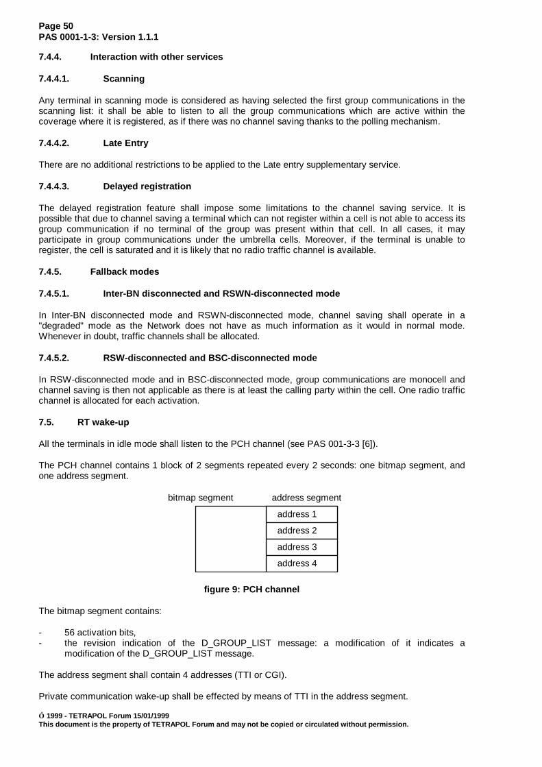
Page 50PAS 0001-1-3: Version 1.1.1
1999 - TETRAPOL Forum 15/01/1999This document is the property of TETRAPOL Forum and may not be copied or circulated without permission.
7.4.4. Interaction with other services
7.4.4.1. Scanning
Any terminal in scanning mode is considered as having selected the first group communications in thescanning list: it shall be able to listen to all the group communications which are active within thecoverage where it is registered, as if there was no channel saving thanks to the polling mechanism.
7.4.4.2. Late Entry
There are no additional restrictions to be applied to the Late entry supplementary service.
7.4.4.3. Delayed registration
The delayed registration feature shall impose some limitations to the channel saving service. It ispossible that due to channel saving a terminal which can not register within a cell is not able to access itsgroup communication if no terminal of the group was present within that cell. In all cases, it mayparticipate in group communications under the umbrella cells. Moreover, if the terminal is unable toregister, the cell is saturated and it is likely that no radio traffic channel is available.
7.4.5. Fallback modes
7.4.5.1. Inter-BN disconnected and RSWN-disconnected mode
In Inter-BN disconnected mode and RSWN-disconnected mode, channel saving shall operate in a"degraded" mode as the Network does not have as much information as it would in normal mode.Whenever in doubt, traffic channels shall be allocated.
7.4.5.2. RSW-disconnected and BSC-disconnected mode
In RSW-disconnected mode and in BSC-disconnected mode, group communications are monocell andchannel saving is then not applicable as there is at least the calling party within the cell. One radio trafficchannel is allocated for each activation.
7.5. RT wake-up
All the terminals in idle mode shall listen to the PCH channel (see PAS 001-3-3 [6]).
The PCH channel contains 1 block of 2 segments repeated every 2 seconds: one bitmap segment, andone address segment.
address 1
address 2
address 3
address 4
bitmap segment address segment
figure 9: PCH channel
The bitmap segment contains:
- 56 activation bits,- the revision indication of the D_GROUP_LIST message: a modification of it indicates a
modification of the D_GROUP_LIST message.
The address segment shall contain 4 addresses (TTI or CGI).
Private communication wake-up shall be effected by means of TTI in the address segment.
Page 51PAS 0001-1-3: Version 1.1.1
1999 - TETRAPOL Forum 15/01/1999This document is the property of TETRAPOL Forum and may not be copied or circulated without permission.
Group calls and talkgroup wake-up shall necessary be effected by means of a CGI in the addresssegment.
MOCH wake-up can be effected in 2 different modes:
- the CGI in the address segment wake-up mode;
- the bitmap activation wake-up mode: the network associates to every MOCH (or emergency orbroadcast MOCH) one of the 56 activation bits.
activation bit = 0: the correponding MOCH is not active,activation bit = 1: the corresponding MOCH is active.
The correspondance between the activation bit and the MOCH is executed thanks to the apparitionorder of the MOCH in the D_GROUP_LIST message. The explicit or implicit numbering mode ischoosen depending on the INDEX_LIST byte of the D_GROUP_LIST message (see the PAS 001-3-2 [5]).
The terminals are then alerted that there is an activation waiting by the periodical diffusion (the period ofwhich depends on the load of the control channel) of a message giving transmit rights to the RTs andcontaining:
- the open channel number or the shared coverage;- the number of the group which has been called (for a group call);- the physical characteristics of the traffic channel;- clear/encrypted mode.
An RT which is not concerned by the call or which is not able to participate in the call because of theencryption mode does not reply. All other participating terminals reply.
7.6. Data polling
7.6.1. Scope
This subclause describes the polling mechanism which is used by applications which need to collectinformation on a periodical basis from the User Data Terminals towards external servers or from the RTstowards an internal handling element (see the datagram periodic polling mode service described in PAS001-1-2 [R3]).
Examples of applications for the polling mechanism are the following ones:
- automatic vehicle location application based on a GPS location;- collect of information from measures realised by means of sensors.
7.6.2. Description
The data polling service is a bearer service which is implemented in the Network and in the RT, whichenables an RT or a UDT data application to periodically transmit data towards an internal server (SADP,RT/UDT) or towards an external server.
7.6.2.1. Activation / deactivation
Activation / deactivation of the polling mechanism is enabled by the RT/UDT application. It alsodetermines the characteristics of polling, that is, the format of the transmitted data and the pollingfrequency.
For each new activation / deactivation, the RT state vector is modified and transmitted to the Network.
On activation confirmation, the application is able to transmit data on the source port declared to be inpolling mode.

Page 52PAS 0001-1-3: Version 1.1.1
1999 - TETRAPOL Forum 15/01/1999This document is the property of TETRAPOL Forum and may not be copied or circulated without permission.
7.6.2.2. Polling principles
Polling is implemented on the RT registration control channel.
Figure 10 gives a representation of the polling mechanism, where the Network periodically polls the RT.
RT side
Messaging appli.
L2
Network side
Messaging appli.
L2
Server
polling request
data
Ack/Nak
UDT
(polling answer)
data
data
data
data
Figure 10: Representation of the polling mechanism
The User Data Terminal transmits to the RT application a message to be transmitted in "polling" mode.
When the RT emits the polling response, the RT shall transmit an acknowledgement message to themessaging application and from there to the User Data Terminal.
When the RT does not have any information to transmit, it shall not transmit anything.
7.6.3. Special features
7.6.3.1. Radio acknowledgement
The RT polling service does not deliver any radio transmission acknowledgement.
The RT polling service delivers a polling acknowledgement. The polling acknowledgement is positivewhen the data has been emitted and negative when the data has not been transmitted (erasure by anewly provided data, no polling, format of the data not compatible with the format indicated in the pollingrequest, ...).
7.6.3.2. Network side polling mechanism (informative)
TR1 TR2 TR3 TR4 TRn TR1TRn-1
D = period for collecting the information
d dd d d
Figure 11: definition of the polling mechanism on the network side
The following information is available to the Network:
- the list of N RTs to be polled;- the polling period D.
The Network shall calculate the d "polling time interval" between the polling of 2 terminals by so as topoll all RTs within the polling period D.
The uplink RT-Network frame shall be transmitted as a datagram. The uplink frame is identical to that ofthe UI_RACH frame.
Page 53PAS 0001-1-3: Version 1.1.1
1999 - TETRAPOL Forum 15/01/1999This document is the property of TETRAPOL Forum and may not be copied or circulated without permission.
In the Network itself the information is transmitted as an uplink datagram on the RACH channel.
7.6.4. Interaction with other services
7.6.4.1. Interaction with voice services
Polling shall have no interaction with voice services during the phases while the communication isinactive.
During a group communication activation, the information collect using the polling shall be possible onlyif the RT/Network information exchange happens when the RT is on the control channel.
7.6.4.2. Interaction with data services
Polling shall have no interaction with any messaging application which does not require polling.
7.6.5. Information handling at application level
7.6.5.1. Service definition
The application in the UDT or the RT using the polling mechanism is unique.
In a Network it is possible to have simultaneously several applications using the polling mechanism withdifferent profiles.
The UDT application can use control and supervision primitives in order to:
- activate the polling service;- modify the parameters of the polling service;- deactivate the polling service;- subscribe a polling acknowledgement.
The application may use the polling acknowledgement to deposit its data on the rhythm of polling: itoperates in "synchronised mode". The application may update its data by delivering them at a rhythmfaster than the rhythm of polling. Only the last data provided to the polling service is transmitted: theapplication operates in "non-synchronised mode".
7.6.5.2. Polling profile
The polling profile defines the characteristics of the polling for a UDT/RT pair. These characteristics aresupplied at polling activation or for polling modification:
- the polling frequency;- the polling answer format.
7.6.5.2.1. Polling frequency
3 frequencies are defined:
- slow f/4;- medium f/2;- fast f.
7.6.5.2.2. Polling answer format
The polling answer format defines the format and length of the data transmitted by the polling service.

Page 54PAS 0001-1-3: Version 1.1.1
1999 - TETRAPOL Forum 15/01/1999This document is the property of TETRAPOL Forum and may not be copied or circulated without permission.
7.6.6. Description of polling applications (informative)
7.6.6.1. Description of an automatic vehicle location (AVL) application (informative)
For informative purposes, this subclause describes a particular application which can be realised usingthe polling mechanism in the network: the automatic vehicle location application based on a GPSlocation.
The GPS application in the UDT shall provide, on its on time schedule the result from the relativedetermination of its location. The TETRAPOL Network shall collect the last information received by theRT on a different schedule (see note) which may in particular depend on the radio traffic.
NOTE: Within a TETRAPOL Network there are 3 different values for the information collect timeinterval.
In case of location information, it is assumed that the last measure is the most accurate and that missinginformation is not relevant.
It shall also be possible for the server to transmit on a periodical basis an absolute location request witha more important volume of information to transmit.
From an operational point of view, the applicative mechanisms shall make it possible for an operator toactivate / deactivate the GPS service for a group of RTs within the entire Network or within a set of cellsand to modify the information collect time interval (hour of activation, radio cells where activation isrequested, ...).
7.6.6.2. Description of a measure information collect (informative)
For informative purposes, this subclause describes a particular application which can be realised usingthe polling mechanism in the network: collect of information from measures realised by means ofsensors. It is similar to the GPS application only the length of the useful information shall be moreimportant than that of the GPS application.

Page 55PAS 0001-1-3: Version 1.1.1
1999 - TETRAPOL Forum 15/01/1999This document is the property of TETRAPOL Forum and may not be copied or circulated without permission.
Three cases are possible:
- the delivery of the measure results and the collect of this information are realised on two differentschedules;
- the sensor application transmit the result of its measures to the RT and this RT sends confirmationthat the former measure was correctly received; the sensor application shall not transmit any newmeasure result before it receives this confirmation;
- the measures loose the routine aspect: if a measure exceeds a given threshold it is necessary tohave secure transmission of this measure. Since polling is a non-acknowledged mechanism theshort datagram service on RACH which provides the required level of security for transmission inthis case shall be used.
7.6.7. Fallback modes
7.6.7.1. RSW-disconnected and BSC-disconnected
The network polling mechanism shall be suspended in RSW-disconnected and in BSC-disconnectedmode.
7.6.7.2. Network saturation
In case of saturation of the Network, the polling time interval can be degraded and shall come back to itsnominal value at the end of this saturation phase.

Page 56PAS 0001-1-3: Version 1.1.1
1999 - TETRAPOL Forum 15/01/1999This document is the property of TETRAPOL Forum and may not be copied or circulated without permission.
History
Document history
Date Status Comment
25 March 1996 Version 0.0.1 First version
30 May 1996 Version 0.0.2 Complement
31 July 1996 Version 0.0.3 Update
31 August 1996 Version 0.0.4 Formatting
30 September 1996 Version 0.0.5 Edition. Version for review
29 October 1996 Version 0.0.6 Include remarks following review
18 November 1996 Version 0.0.7 Restructure
16 December 1996 Version 0.1.0 Update cell selection / cell reselection after review
7 February 1997 Version 0.1.1 Add registration, attach/detach, enable/disable
29 March 1997 Version 0.1.2 Add channel saving, polling
10 April 1997 Version 0.1.3 Reorganisation of the contents
16 April 1997 Version 0.1.4 New version after preliminary review
30 April 1997 Version 0.1.5 Update cell selection
13 November 1997 Version 0.2.1 §4.1 addressing and §6.1trunking re-edited
30 December 1997 Version 0.2.2 Editorial corrections
30 January 1998 Version 1.0.0 TWG approval
19 march 1998 Version 1.0.1 Update (DCH, multi-organization) and corrections
27 April 1998 Version 1.1.0 Approbation
15 January 1999 Version 1.1.1 Editorial corrections