tf 204-r-21 tech fact
TRANSCRIPT

1
Welded Wire Reinforced Tilt-up Wall Panels
The popularity of site cast tilt-up wall panels, like that of almost all other forms of precast
concrete, has increased greatly in recent years. They are not only durable and economical
but offer almost endless possibilities for interesting and attractive appearances. These can
be obtained by using various combinations of exposed aggregate, concrete produced from
different cements or with admixed colors, surface treatment, patterned forms, raised or
depressed moldings, and they may be insulated internally as sandwich panels. Panels may
be used structurally and architecturally in load-bearing and non-load-bearing (or curtainwall)
assemblies, in both exterior and interior exposed conditions. Modern tilt-up construction is
incredibly versatile, with highly complex, multistory panels capable of being designed and
erected to suit all manner of building type.
Tilt-up wall panels are commonly cast with window, door, utility, or ornamental openings, or
they may be solid elements absent of fenestration. Though they are typically wide structural
elements, the architectural layout may require the introduction of relatively narrow “pier type”
members which serve as mullions or form ribs in decorative arrangements. The cross-
section is usually solid, although it may be cored to reduce weight or formed in sandwich
fashion around insulation.
Tilt-up wall panels are distinguished from other forms of precast units since they are cast at
the job site rather than cast at a precast concrete manufacturing plant. The basic procedure
involves casting the members on a horizontal surface, usually a floor slab, and lifting them
sequentially into a vertical position to form the building wall.
Tilt-up panels are cast on finished floor slabs with their lower ends typically aligned to be positioned in as close of a proximity as possible to the edge of the building. They are then
lifted by way of cable connections to cast-in lugs or inserts positioned at the upper end and
intermediate locations along the panel length, allowing for the panels to be safely rotated
about the lower end into a vertical plane. Once plumbed, the wall panels are temporarily
braced until final connectivity to sufficiently completed structural floor and roof diaphragms
can be carried out.
Most tilt-up panels are cast face down (exterior side down), with panel inserts cast into the
upward face (interior side).
TF 204-R-21
TECH FACT
Excellence Set in Concrete® For more information on WWR visit our website.
WireReinforcementInstitute.org
• Tech Facts
• Case Studies
• Producer Plants
• Online Learning
• Videos

2
There are numerous advantages that make the tilt-up procedure economical in a variety of circumstances. To begin
with, the absence of the large plant eliminates the need for sizeable investment in fixed facilities. Another benefit is
that shipping costs are almost always lower, as it is far cheaper to move raw materials than finished panelized
products that have sizes and weights in excess of that which can be accommodated by standard transportation
methods. Panels cast on site also not only require less handling, which reduces the likelihood of damage, but the
logistics of storage and staging are also greatly simplified if not altogether eliminated. Finally, the expense of bottom
forms is eliminated since the wall units are either cast on a floor slab or directly on top of each other.
Perhaps the most important feature in tilt-up wall construction is reduction or elimination of size restrictions. Since
most plant-cast members must be moved by truck, their width is generally limited to about 8’-0”, although sometimes
wider shipments can be arranged. Maximum weights and lengths are also regulated by law, and extremely long and
heavy pieces, unless prestressed, may require elaborate and expensive precautions to avoid breakage in transit.
Permissible size and weight may also be governed by handling equipment in the plant or at the site.
However, for the panel cast at the site these are comparatively minor challenges. Width and length can be of any
convenient dimension up to the maximum weight that can be raised with lifting equipment. Greater thicknesses and
weights may be required and this, too, is of less concern with site casting.
While some tilt-up panels have been prestressed, by far the greater portion of them have been of mild reinforced
design. The reinforcement will perform several important functions:
1. To assist in carrying the vertical loads as bearing walls.
2. To resist wind, earthquake, and other lateral forces. Welded wire reinforcement (WWR), with high strength wires accurately spaced, is well suited for all of these uses.
3. To prevent damage due to lifting and handling stresses.
4. To increase the resistance of the surface to cracking because of shrinkage and temperature changes.
The action of precast panels is similar to that of other reinforced concrete members, and their design is very much like
that of cast-in-place walls. Three kinds of forces must be considered; horizontal in-plane and out-of-plane force in the
form of wind and seismic loading, the vertical self-weight of the member, and the vertical and rotational forces imposed
by roof and floor members deriving support directly from the wall panel itself.
A complete discussion of the design of tilt-up panels is beyond the scope of this brochure. High strength welded wire
reinforcement with yield strength up to 80,000 psi is a viable and cost-effective reinforcement material. Structural
spacings of 3” to 18” can be provided with wire sizes up to D31 (5/8” diameter). It is recommended that design
professionals utilize ACI 551 (Guide to Tilt-Up Wall Construction), ACI 318 (Building Code Requirements for Structural
Concrete) and the Tilt-Up Concrete Association’s Engineering Tilt-Up to establish appropriate routines and procedures
for tilt-up wall panel design.
Checklist when preparing architectural/engineering project drawings:
Elevations – Exterior architectural elevations showing panel dimensions, jointing, openings, areas of special treatment
such as facing aggregates, reveals, form liners, and scuppers.
Details – Architectural details showing bevels, miters, chamfers, tapered recesses, door and window conditions,
roofing, and flashing connections.
Panel elevation – Panel elevations drawn from the viewpoint of the fabricator (will panel be cast face up or face down)
showing typical reinforcement and special reinforcement at major and minor openings. Each panel should be uniquely
numbered.
Key plan – Key plan to indicate location of panels and panel designation.
Structural details – Structural details showing typical thickness (is facing aggregate and grout or architectural relief
included in the structural thickness) and special thicknesses and widths of pilasters.
Reinforcement – Reinforcement details showing typical placement and clear cover requirements, pilaster
reinforcement and tie configurations and welded wire reinforcement or rebar dowels for slab connection.

3
Connection details – Connection details showing anchor devices, embedded structural steel, base grouting, and
connecting materials.
Miscellaneous details – Other items include necessity for mechanical and electrical coordination of openings, sleeves,
conduits, and junction boxes.
Specifications – Specifications should include the specified compressive strength of concrete at 28 days, design yield
strength of reinforcement, minimum strength, and density of concrete at time of lift, and allowable lift stresses.
Requirements, if considered necessary, of a sample panel to include finishes, miters, corners, and other details.
Shop drawings – The contractor should be required to submit shop drawings which depict each panel.
ACI 318-19 provides useful prescriptions for minimum reinforcement required in tilt-up wall panels required to resist low
levels of internal in-plane shear. Note that for tilt-up wall panels with higher levels of in-plane shear, the threshold for
minimum steel is considerably higher. Table 1 shows these steel areas derived for common wall thicknesses. The
delineation between low and high levels of in-plane shear is as follows:
𝑉𝑢 = 0.5 × 𝜑 × 𝑎𝑐 × √𝑓′𝑐 × 𝐴𝑐𝑣
where:
𝑉𝑢 = 𝑓𝑎𝑐𝑡𝑜𝑟𝑒𝑑 𝑖𝑛 𝑝𝑙𝑎𝑛𝑒 𝑠ℎ𝑒𝑎𝑟 𝑓𝑜𝑟𝑐𝑒 (𝑙𝑏)
𝜑 = 𝑠𝑡𝑟𝑒𝑛𝑔𝑡ℎ 𝑟𝑒𝑑𝑢𝑐𝑡𝑖𝑜𝑛 𝑓𝑎𝑐𝑡𝑜𝑟
𝑎𝑐 = 𝑐𝑜𝑒𝑓𝑓𝑖𝑐𝑖𝑒𝑛𝑡 𝑑𝑒𝑓𝑖𝑛𝑖𝑛𝑔 𝑡ℎ𝑒 𝑟𝑒𝑙𝑎𝑡𝑖𝑣𝑒 𝑐𝑜𝑛𝑡𝑟𝑖𝑏𝑢𝑡𝑖𝑜𝑛 𝑜𝑓 𝑐𝑜𝑛𝑐𝑟𝑒𝑡𝑒 𝑠𝑡𝑟𝑒𝑛𝑔𝑡ℎ 𝑡𝑜 𝑛𝑜𝑚𝑖𝑛𝑎𝑙 𝑤𝑎𝑙𝑙 𝑠ℎ𝑒𝑎𝑟 𝑠𝑡𝑟𝑒𝑛𝑔𝑡ℎ
𝜆 = 𝑚𝑜𝑑𝑖𝑓𝑖𝑐𝑎𝑡𝑖𝑜𝑛 𝑓𝑎𝑐𝑡𝑜𝑟 𝑓𝑜𝑟 𝑐𝑜𝑛𝑐𝑟𝑒𝑡𝑒 𝑢𝑛𝑖𝑡 𝑤𝑒𝑖𝑔ℎ𝑡
𝑓′𝑐 = 𝑠𝑝𝑒𝑐𝑖𝑓𝑖𝑒𝑑 𝑐𝑜𝑚𝑝𝑟𝑒𝑠𝑠𝑖𝑣𝑒 𝑠𝑡𝑟𝑒𝑛𝑔𝑡ℎ 𝑜𝑓 𝑐𝑜𝑛𝑐𝑟𝑒𝑡𝑒 (𝑝𝑠𝑖)
𝐴𝑐𝑣 = 𝑔𝑟𝑜𝑠𝑠 𝑠𝑒𝑐𝑡𝑖𝑜𝑛 𝑜𝑓 𝑐𝑜𝑛𝑐𝑟𝑒𝑡𝑒 𝑠𝑒𝑐𝑡𝑖𝑜𝑛 𝑖𝑛 𝑡ℎ𝑒 𝑑𝑖𝑟𝑒𝑐𝑡𝑖𝑜𝑛 𝑜𝑓 𝑠ℎ𝑒𝑎𝑟 𝑓𝑜𝑟𝑐𝑒 𝑐𝑜𝑛𝑠𝑖𝑑𝑒𝑟𝑒𝑑 (𝑖𝑛2)
It is important to note that applied structural loading often results in internal forces and moments that require
significantly higher cross-sectional areas of steel reinforcement than those presented in Table 1. Areas of reinforcing
steel must be derived and detailed by the design professional to ensure that satisfactory demand-to-capacity ratios and
serviceability requirements are maintained.

4
Minimum Steel Area – Longitudinal and Transverse Directions
Wall Thickness Low In-Plane Shear Level:
Steel Area (in2 per linear foot) High In-Plane Shear Level:
Steel Area (in2 per linear foot)
4” 0.048 0.12
4½” 0.054 0.135
5” 0.060 0.15
5½” 0.066 0.165
6” 0.072 0.18
6½” 0.078 0.195
7” 0.084 0.21
7½” 0.09 0.225
8” 0.096 0.24
8½” 0.102 0.255
9” 0.108 0.27
9½” 0.114 0.285
10” 0.120 0.3
10½” 0.126 0.315
11” 0.132 0.33
11½” 0.138 0.345
12” 0.144 0.36
Tilt-Up Wall Panel Design Example
Objective:
Using ACI 318-19 as the design standard, derive the required steel reinforcement of wall panel and provide general
configuration of WWR mats corresponding to an originally-specified reinforcing bar arrangement.
Inputs:
• Panel is 25’-0” wide by 35’-0” tall. The panel is formed with two penetrations, each 11’-0” wide x 7’-0” high.
• Panel structural thickness is 9½". Reinforcement is placed in each face of the panel, with the vertical
reinforcing positioned one-inch clear of the panel surfaces and the horizontal reinforcing located to the inside
of the verticals. Maintain a two-inch offset dimension between reinforcing and panel edges and penetrations.
• Panel concrete is normal-weight, with a 28-day compressive strength of 4,000 psi. Yield strength of reinforcing
is 80,000 psi. The design professional requires a minimum reinforcement ratio for each face of the wall panel
equal to 0.0010.
• The panel supports open web steel roof joists at 30” below its top edge. An interior slab-on-ground aligns at
24” above the panel’s bottom edge.
• The wall panel derives out-of-plane restraint from the roof framing (itself securely connected to the steel deck
roof diaphragm) and via dowel connection to the slab-on-ground (itself designed to behave as a diaphragm
capable of transmitting loads to the subsurface). The wall derives vertical support from continuous bearing of
the wall panel on a properly-design continuous footing below.

5
• Gravity loading is incurred from vertical dead and roof live loads at the roof elevation, in addition to dead load
of the panel self weight. The application of roof loading in the structural model accounts for the eccentric
positioning of the roof framing support points relative to the wall panel centerline.
• Lateral loading in the form of out-of-plane wind forces and out-of-plane seismic forces are included in the
design.
• Lateral loading from in-plane wind and in-plane seismic forces is minimal. It has been determined that the
panel is stable against overturning and that no positive mechanical attachment between the base of the wall
and the top of the foundation is required.
• The effects of thermal bowing have been duly considered.
There are three primary methods for translating steel areas derived during design into the detailed arrangements
presented on contract drawings intended for construction. These methods are listed below.
1. Quantity-Based
2. Spacing-Based
3. Area-Based
Worth noting is that most modern reinforced concrete structural engineering software packages are capable of
providing fundamental outputs to the designer in the form of area-based results. A large majority of these software
packages take this output a step further and offer results on a quantity and/or spacing basis, with ACI-prescribed
maximum spacings and prescriptive minimum reinforcement ratios being considered during the process of compiling
the output.
Figure 100: Wall panel geometry
and analytical model
6
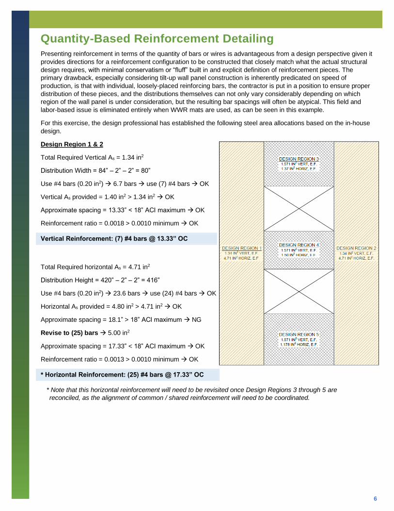
Quantity-Based Reinforcement Detailing Presenting reinforcement in terms of the quantity of bars or wires is advantageous from a design perspective given it
provides directions for a reinforcement configuration to be constructed that closely match what the actual structural
design requires, with minimal conservatism or “fluff” built in and explicit definition of reinforcement pieces. The
primary drawback, especially considering tilt-up wall panel construction is inherently predicated on speed of
production, is that with individual, loosely-placed reinforcing bars, the contractor is put in a position to ensure proper
distribution of these pieces, and the distributions themselves can not only vary considerably depending on which
region of the wall panel is under consideration, but the resulting bar spacings will often be atypical. This field and
labor-based issue is eliminated entirely when WWR mats are used, as can be seen in this example.
For this exercise, the design professional has established the following steel area allocations based on the in-house
design.
Design Region 1 & 2
Total Required Vertical As = 1.34 in2
Distribution Width = 84” – 2” – 2” = 80”
Use #4 bars (0.20 in2) → 6.7 bars → use (7) #4 bars → OK
Vertical As provided = 1.40 in2 > 1.34 in2 → OK
Approximate spacing = 13.33” < 18” ACI maximum → OK
Reinforcement ratio = 0.0018 > 0.0010 minimum → OK
Vertical Reinforcement: (7) #4 bars @ 13.33” OC
Total Required horizontal As = 4.71 in2
Distribution Height = 420” – 2” – 2” = 416”
Use #4 bars (0.20 in2) → 23.6 bars → use (24) #4 bars → OK
Horizontal As provided = 4.80 in2 > 4.71 in2 → OK
Approximate spacing = 18.1” > 18” ACI maximum → NG
Revise to (25) bars → 5.00 in2
Approximate spacing = 17.33” < 18” ACI maximum → OK
Reinforcement ratio = 0.0013 > 0.0010 minimum → OK
* Horizontal Reinforcement: (25) #4 bars @ 17.33” OC
* Note that this horizontal reinforcement will need to be revisited once Design Regions 3 through 5 are
reconciled, as the alignment of common / shared reinforcement will need to be coordinated.

7
Design Region 3
Total Required Vertical As = 1.571 in2
Distribution Width = 132” + 2” + 2” = 136”
Use #4 bars (0.20 in2) → 7.9 bars → use (8) #4 bars →
OK
Vertical As provided = 1.60 in2 > 1.571 in2 → OK
Approximate spacing = 15.11” < 18” ACI maximum → OK
Reinforcement ratio = 0.0013 > 0.0010 minimum → OK
Vertical Reinforcement: (8) #4 bars @ 15.11” OC
Total Required horizontal As = 1.37 in2
Distribution Height = 84” – 2” – 2” = 80”
Use #4 bars (0.20 in2) → 6.9 bars → use (7) #4 bars →
OK
Horizontal As provided = 1.40 in2 > 1.37 in2 → OK
Approximate spacing = 13.33” < 18” ACI maximum → OK
Reinforcement ratio = 0.0018 > 0.0010 minimum → OK
Horizontal Reinforcement: (7) #4 bars @ 13.33” OC

8
Design Region 4
Total Required Vertical As = 1.571 in2
Vertical Reinforcement: (8) #4 bars @ 15.11” OC
Total Required horizontal As = 1.50 in2
Distribution Height = 72” – 2” – 2” = 68”
Use #4 bars (0.20 in2) → 7.5 bars → use (8) #4 bars →
OK
Horizontal As provided = 1.60 in2 > 1.50 in2 → OK
Approximate spacing = 9.71” < 18” ACI maximum → OK
Reinforcement ratio = 0.0023 > 0.0010 minimum → OK
Horizontal Reinforcement: (8) #4 bars @ 9.71” OC
Design Region 5
Total Required Vertical As = 1.571 in2
Vertical Reinforcement: (8) #4 bars @ 15.11” OC
Total Required horizontal As = 1.178 in2
Distribution Height = 96” – 2” – 2” = 92”
Use #4 bars (0.20 in2) → 5.9 bars → use (6) #4 bars →
OK
Horizontal As provided = 1.20 in2 > 1.178 in2 → OK
Approximate spacing = 18.4” > 18” ACI maximum → NG
Revise to (7) bars → 1.40 in2
Approximate spacing = 15.33” < 18” ACI maximum → OK
Reinforcement ratio = 0.0015 > 0.0010 minimum → OK
Horizontal Reinforcement: (7) #4 bars @ 15.33” OC

9
Revisit Design Region 1 & 2
Originally calculated:
Horizontal Reinforcement: (25) #4 bars @ 17.33” OC
Horizontal bars from Regions 3, 4, and 5 will run
continuous for the full width of the wall panel, in effect
superseding the requirements for Region 1 and 2 in the
zones where there is regional overlap:
Design Region 3 horizontals: (7) #4
Design Region 4 horizontals: (8) #4
Design Region 5 horizontals: (7) #4
Remaining Region 1 and 2 horizontals:
25 – 7 – 8 – 7 = (3) #4 bars
By inspection, then, while helping to satisfy the “overall”
horizontal reinforcement requirement originally calculated
for the full height of Regions 1 and 2, three (3) leftover #4
bars will not be sufficient to populate the orange-shaded
jamb areas to each side of the wall penetrations. As
such, calculate the necessary reinforcement for these
shaded areas based on ACI prescribed maximum
spacing and the designer’s minimum reinforcement ratio:
Distribution Height = 84” + 2” + 2” = 88”
Based on 18” ACI spacing = 4.88 spaces → 5 spaces
Resulting interior spacing = 17.6” OC → OK
Use (4) #4 bars → 0.80 in2
Reinforcement ratio = 0.0009 < 0.001 → NG
Revise to (5) #4 bars → 1.00 in2
Resulting interior spacing = 14.67” OC → OK
Reinforcement Ratio = 0.0012 > 0.001 → OK
Provide (5) #4 bars @ 14.67” OC
Total for Region 1 and Region 2:
7 + 8 + 7 + 5 + 5 = 32 bars > 25 bars original → OK

10
The illustration below shows tha result of the design professional’s efforts, as would be illustrated on the contract
drawings for construction. Note that the designer has identified specific quantities of bars to closely match the cross-
sectional steel areas derived in design, and he/she has provided direction for even spacing / equal distribution
throughout the wall regions in which the bars are positioned on the drawing. The designer has also established a
prescriptive maximum spacing, simply echoing what is defined in ACI 318-19. With that said, it will still be the
contractor’s responsibility to carry out the necessary field bookkeeping on the multitude of spacings and regional
extents of the bars quantified therein.

11
The resulting constructed arrangement of loose tied reinforcing bars is shown below (miscellaneous trim, diagonal
corner bars, and slab dowels not shown).
Notice the variation in spacings, most of which are in atypical, fractional intervals.

12
It mat be simpler for the contractor to provide the design professional’s specified reinforcement in WWR form. Doing
so eliminates the labor and coordination required with placement of individual loose pieces of reinforcement, and
allows for the full arrangement to be resolved in modular form. A WWR solution is presented below. Colors are used
to differentiate between vertical and horizontal WWR mats. All wires are D20.0, equivalent in size to the originally-
specified #4 reinforcing bars (note that wire sizes are commonly available up to D31.0, equivalent in size to a #5
bar). Overall wire quantity is identical to the original specification, but spacings are slightly adjusted as shown to be
more reflective of “common” intervals.

13
An exploded view of the WWR solution is presented below. Instead of the contractor handling, placing, and tying 80
individual pieces of reinforcement into each face of the wall panel forms, five (5) WWR mats can be positioned and
secured as a potential simplification to the installation process, and a reduction of its duration.
14
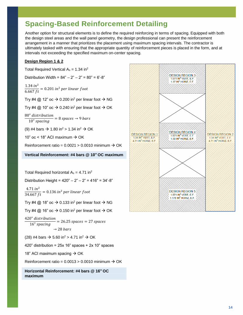
Spacing-Based Reinforcement Detailing Another option for structural elements is to define the required reinforcing in terms of spacing. Equipped with both
the design steel areas and the wall panel geometry, the design professional can present the reinforcement
arrangement in a manner that prioritizes the placement using maximum spacing intervals. The contractor is
ultimately tasked with ensuring that the appropriate quantity of reinforcement pieces is placed in the form, and at
intervals not exceeding the specified maximum on-center spacing.
Design Region 1 & 2
Total Required Vertical As = 1.34 in2
Distribution Width = 84” – 2” – 2” = 80” = 6’-8”
1.34 𝑖𝑛2
6.667 𝑓𝑡= 0.201 𝑖𝑛2 𝑝𝑒𝑟 𝑙𝑖𝑛𝑒𝑎𝑟 𝑓𝑜𝑜𝑡
Try #4 @ 12” oc → 0.200 in2 per linear foot → NG
Try #4 @ 10” oc → 0.240 in2 per linear foot → OK
80" 𝑑𝑖𝑠𝑡𝑟𝑖𝑏𝑢𝑡𝑖𝑜𝑛
10" 𝑠𝑝𝑎𝑐𝑖𝑛𝑔= 8 𝑠𝑝𝑎𝑐𝑒𝑠 → 9 𝑏𝑎𝑟𝑠
(9) #4 bars → 1.80 in2 > 1.34 in2 → OK
10” oc < 18” ACI maximum → OK
Reinforcement ratio = 0.0021 > 0.0010 minimum → OK
Vertical Reinforcement: #4 bars @ 10” OC maximum
Total Required horizontal As = 4.71 in2
Distribution Height = 420” – 2” – 2” = 416” = 34’-8”
4.71 𝑖𝑛2
34.667 𝑓𝑡= 0.136 𝑖𝑛2 𝑝𝑒𝑟 𝑙𝑖𝑛𝑒𝑎𝑟 𝑓𝑜𝑜𝑡
Try #4 @ 18” oc → 0.133 in2 per linear foot → NG
Try #4 @ 16” oc → 0.150 in2 per linear foot → OK
420" 𝑑𝑖𝑠𝑡𝑟𝑖𝑏𝑢𝑡𝑖𝑜𝑛
16" 𝑠𝑝𝑎𝑐𝑖𝑛𝑔= 26.25 𝑠𝑝𝑎𝑐𝑒𝑠 = 27 𝑠𝑝𝑎𝑐𝑒𝑠
→ 28 𝑏𝑎𝑟𝑠
(28) #4 bars → 5.60 in2 > 4.71 in2 → OK
420” distribution = 25x 16” spaces + 2x 10” spaces
18” ACI maximum spacing → OK
Reinforcement ratio = 0.0013 > 0.0010 minimum → OK
Horizontal Reinforcement: #4 bars @ 16” OC
maximum

15
Design Region 3
Total Required Vertical As = 1.571 in2
Distribution Width = 132” + 2” + 2” = 136” = 11’-4”
1.571 𝑖𝑛2
11.333 𝑓𝑡= 0.139 𝑖𝑛2 𝑝𝑒𝑟 𝑙𝑖𝑛𝑒𝑎𝑟 𝑓𝑜𝑜𝑡
Try #4 @ 18” oc → 0.133 in2 per linear foot → NG
Try #4 @ 16” oc → 0.150 in2 per linear foot → OK
132" 𝑑𝑖𝑠𝑡𝑟𝑖𝑏𝑢𝑡𝑖𝑜𝑛
16" 𝑠𝑝𝑎𝑐𝑖𝑛𝑔= 8.25 𝑠𝑝𝑎𝑐𝑒𝑠 = 9 𝑠𝑝𝑎𝑐𝑒𝑠 → 8 𝑏𝑎𝑟𝑠
(8) #4 bars → 1.80 in2 > 1.34 in2 → OK
132” distribution = 7x 16” spaces + 2x 10” spaces
18” ACI maximum spacing → OK
Reinforcement ratio = 0.0013 > 0.0010 minimum → OK
Vertical Reinforcement: #4 bars @ 16” OC maximum
Total Required horizontal As = 1.37 in2
Distribution Height = 84” – 2” – 2” = 80” = 6’-8”
1.37 𝑖𝑛2
6.667 𝑓𝑡= 0.206 𝑖𝑛2 𝑝𝑒𝑟 𝑙𝑖𝑛𝑒𝑎𝑟 𝑓𝑜𝑜𝑡
Try #4 @ 12” oc → 0.200 in2 per linear foot → NG
Try #4 @ 10” oc → 0.240 in2 per linear foot → OK
80" 𝑑𝑖𝑠𝑡𝑟𝑖𝑏𝑢𝑡𝑖𝑜𝑛
10" 𝑠𝑝𝑎𝑐𝑖𝑛𝑔= 8 𝑠𝑝𝑎𝑐𝑒𝑠 → 9 𝑏𝑎𝑟𝑠
(9) #4 bars → 1.80 in2 > 1.37 in2 → OK
18” ACI maximum spacing → OK
Reinforcement ratio = 0.0021 > 0.0010 minimum → OK
Horizontal Reinforcement: #4 bars @ 10” OC
maximum

16
Design Region 4
Total Required Vertical As = 1.571 in2
Vertical Reinforcement: #4 bars @ 16” OC maximum
Total Required horizontal As = 1.50 in2
Distribution Height = 72” – 2” – 2” = 68” = 5’-8”
1.50 𝑖𝑛2
5.667 𝑓𝑡= 0.265 𝑖𝑛2 𝑝𝑒𝑟 𝑙𝑖𝑛𝑒𝑎𝑟 𝑓𝑜𝑜𝑡
Try #4 @ 10” oc → 0.240 in2 per linear foot → NG
Try #4 @ 8” oc → 0.300 in2 per linear foot → OK
68" 𝑑𝑖𝑠𝑡𝑟𝑖𝑏𝑢𝑡𝑖𝑜𝑛
8" 𝑠𝑝𝑎𝑐𝑖𝑛𝑔= 8.5 𝑠𝑝𝑎𝑐𝑒𝑠 = 9 𝑠𝑝𝑎𝑐𝑒𝑠 → 10 𝑏𝑎𝑟𝑠
(10) #4 bars → 2.00 in2 > 1.50 in2 → OK
18” ACI maximum spacing → OK
Reinforcement ratio = 0.0026 > 0.0010 minimum → OK
Horizontal Reinforcement: #4 bars @ 8” OC
maximum
Design Region 5
Total Required Vertical As = 1.571 in2
Vertical Reinforcement: #4 bars @ 16” OC maximum
Total Required horizontal As = 1.178 in2
Distribution Height = 96” – 2” – 2” = 92” = 7’-8”
1.178 𝑖𝑛2
7.667 𝑓𝑡= 0.154 𝑖𝑛2 𝑝𝑒𝑟 𝑙𝑖𝑛𝑒𝑎𝑟 𝑓𝑜𝑜𝑡
Try #4 @ 16” oc → 0.150 in2 per linear foot → NG
Try #4 @ 14” oc → 0.171 in2 per linear foot → OK
92" 𝑑𝑖𝑠𝑡𝑟𝑖𝑏𝑢𝑡𝑖𝑜𝑛
14" 𝑠𝑝𝑎𝑐𝑖𝑛𝑔= 6.6 𝑠𝑝𝑎𝑐𝑒𝑠 = 7 𝑠𝑝𝑎𝑐𝑒𝑠 → 8 𝑏𝑎𝑟𝑠
(8) #4 bars → 1.60 in2 > 1.178 in2 → OK
92” distribution = 5x 14” spaces + 2x 11” spaces
18” ACI maximum spacing → OK
Reinforcement ratio = 0.0015 > 0.0010 minimum → OK
Horizontal Reinforcement: #4 bars @ 14” OC
maximum

17
While the spacing-based approach to specifying reinforcement in a wall panel remains a popular and straighforward
method from the design professional’s perspective, and is also well represented in structural engineering software
packages, it is important to recognize that in the field it can often yield conservative quantities of reinforcement actually
needing to be put in place.
The spacing-based approach is a natural fit for large expanses of uninterrupted and/or repetitive planes of structural
wall and slab, and in those cases is justifiably the method of choice for the engineer’s specification of reinforcement. But
considering tilt-up wall construction is inherently panelized and characterized by numerous separations, penetrations,
and variation in geometric regions, the introduction of a single additional bar or wire within a given region on a given wall
panel, numerous times over on a given project, can result in a significant increase in the steel package when compared
to the more refined quantity-based approach.
For comparison, the “real” reinforcement amounts in the field for Quantity-Based and Spacing-Based methods are
shown below. Notice the increase in quantity of individual pieces of reinforcement when using the Spacing-Based
method.
Individual Pieces of Reinforcement Required
Region Quantity Basis Spacing Basis
1 Vertical 7 9
Horizontal 10 10
2 Vertical 7 9
Horizontal 10 10
3 Vertical 8 8
Horizontal 7 9
4 Vertical 8 8
Horizontal 8 10
5 Vertical 8 8
Horizontal 7 8
TOTAL PIECES PER PANEL FACE 80 89
In both cases, the use of WWR can be tremendously advantageous. The WWR detailer will handle the task of
configuring the reinforcement to suit the design professional’s selected method of specification, and the end result in
the field will be a quickly-installed, modular solution consisting of just five (5) pre-configured WWR mats in each face
of the wall panel.
WWR
Region Quantity Basis Spacing Basis
1 Vertical 7 9
Horizontal 10 10
2 Vertical 7 9
Horizontal 10 10
3 Vertical 8 8
Horizontal 7 9
4 Vertical 8 8
Horizontal 8 10
5 Vertical 8 8
Horizontal 7 8
TOTAL WWR MATS PER PANEL FACE 5 5

18
Area-Based Reinforcement Detailing At first glance for the design professional, the area-based specification of reinforcement would seemingly be the
simplest approach, as it would in large part consist of the direct translation of the most rudimentary reinforced
concrete design output onto the construction drawings. No doubt this method has merit, and there is precedence for
its use, but it is critical that the design professional establish prescriptive requirements to ensure such a simplistic
approach is properly communicated to and interpreted by the fabricator and contractor.
An example of required “additional” guidelines for an area-based approach to specification of steel reinforcement in
tilt-up wall panels is outlined below.
1. Reinforcing steel shall consist of welded deformed wire and/or deformed reinforcing bars. Refer to general notes and project specifications for applicable material ASTM standards and required mechanical properties.
2. To ensure effective design depths are not compromised, the maximum diameter of reinforcement shall be 3/4”. Minimum diameter of reinforcement shall be 1/4”.
3. Minimum centerline-to-centerline spacing of reinforcement is 2”. Maximum centerline-to-centerline spacing of reinforcement is 18”.
4. Vertical bars/wires shall be continuous between the bottom and top of the wall panel unless interrupted by formed wall penetration locations. Horizontal bars/wires shall be continuous between the vertical edges of the wall panel unless interrupted by formed wall penetration locations.
5. Where the layout of bars/wires is such that their path traverses more than one illustrated reinforcement region, and the specified steel areas for those regions is different, the larger steel area shall be used for the full length of the bars/wires.
6. Reinforcement layout shall coordinate with the positioning of embedded steel plates and formed pockets without interruption. Where interruption of individual bars/wires is unavoidable, refer to typical details for required introduction of added bars/wires to ensure continuity of reinforcement is maintained at plate and pocket locations. Lift inserts and other related lifting hardware shall be positioned to avoid reinforcement.
Commentary
C1. This note allows the contractor to user both types of deformed structural reinforcement in the wall panels –
welded wire reinforcement mats and/or deformed bars.
C2. The dimension between the centerline of reinforcement in the tensile face and the extreme compression fiber
of the wall panel is a design attribute used to calculate capacities. As the diameter of the reinforcement
increases, the dimension decreases, which corresponds to a reduction in capacities. As such, it is important
to establish a maximum diameter that is representative of dimensional criteria used in the original design
calculations. The design professional can also elect to establish a minimum diameter.
C3. ACI provisions for minimum and maximum spacings should be reiterated on contract drawings wherever
precise spacings or positioning are not explicitly defined.
C4. Reinforcement continuity is critical to the structural performance of the wall panel. The vast majority of tilt-up
wall panels are vertically-spanning, necessitating the vertical continuity of bars/wires from top to bottom of the
panel. Likewise, continuity of horizontal reinforcement is also required, and especially critical in those
conditions where the presence of formed penetrations result in spandrel portions of the wall panel that rely on
horizontal-spanning behavior to redistribute the effects of loading into the uninterrupted vertical “piers” of the
wall panel. Penetrations in wall panels are of course very common, so the continuity of both vertical and
horizontal reinforcement in the piers and spandrels that surround these openings is the basis for wall panel’s
strength and stability.

19
C5. For area-based specification of reinforcement, the definitions of vertical and horizontal reinforcement cross-
sectional area requirements is largely “region” based. Invariably there will be instances where the continuity of
reinforcing wires/bars themselves is such that they pass through more than one illustrated region. When this
occurs, the obvious requirement is for these wires/bars to adopt the largest cross-sectional area of the regions
traversed.
C6. Wall panels always contain various arrangements of embedded steel components and formed pockets for
support of structural framing and other structural connectivity. The positioning of these plates and pockets will
generally take precedence, so the layout of reinforcement must account for their presence while still satisfying
the overall specified reinforcement requirement. When a scenario arises such that interruption of a wire or bar is
unavoidable, the design professional is obligated to provide typical details showing the introduction of additional
continuity wires/bars around the interrupted location such that reinforcement continuity is maintained.
Here is an example of a WWR solution that is not only very
straightforward in its derivation, but refines the steel areas provided
to match closely to those specified, resulting in a steel package with
maximum economy. As discussed previously in this Tech Fact,
depending on the project size and the associated tonnage of steel
reinforcement, it is very common for manufacturers to draw
“custom” wire sizes to specific diameters to suit specified steel
areas, thereby fine-tuning the constructed solution to match the
specified design.
Here the solution is comprised of just two design-specific sizes:
D17.2 and D22.5, each of which is spaced to satisfy both the
region-based steel area requirements while conforming to the
specified maximum (and minimum) spacing, minimum
reinforcement ratio, and minimum reinforcement diameter.

20
Illustrated below is the exploded view of the area-based WWR solution.

21
A summary of options for comparison is compiled below. An area basis for loose rebar is not reflected here, as it will
essentially look identical to the results of the Quantity-Based method for rebar since fractional sizes are not available
in reinforcing bars.
Attribute
Quantity Basis Spacing Basis Area Basis
WWR Loose Rebar WWR Loose Rebar WWR
Total Pieces 160 160 178 178 142
Placement Pieces 10 160 10 178 10
Steel Weight per Face
901.744 LB* 899.26 LB 1,080.05LB* 1,077.57 LB 854.50 LB
Total Weight 1,803.49 LB 1,798.52 LB 2,160.10 LB 2,155.14 LB 1,709.00 LB
Conventional Spacing?
YES NO YES YES YES
Spacing Defined on Drawings?
Prescriptive min/max only Yes Prescriptive
min/max only
* Note: slight difference in weight of WWR when compared to loose rebar is due to the additional 1/2" long extensions
necessary at wire terminations adjacent to welded intersections. These extensions facilitate the automatic welding process
and ensure a suitable weld is achieved.
Tilt-up wall construction is a natural fit for the implementation of welded wire reinforcement solutions, and offers a
modern example of the interchangeability and versatility of WWR usage in structural elements. When combined with
selective use of deformed reinforcing bars, all tilt-up wall panel reinforcement configurations are scalable.
Disclaimer
This publication and its contents, including, but not limited to, textual material, graphs, tables, charts, calculations,
statistics, photographs and/or drawings are made available by the WRI “AS IS” and as an informational resource
only. WRI, its officers, directors, employees, agents, contractors, volunteers, members and consultants DISCLAIM
ANY AND ALL EXPRESS AND IMPLIED WARRANTIES, CONDITIONS, REPRESENTATIONS, OR OTHER
TERMS (INCLUDING AS TO SATISFACTORY QUALITY, FITNESS FOR A PARTICULAR PURPOSE,
SUITABILITY OR MERCHANTABILITY) with respect to the publication and its contents. To the fullest extent
permitted by applicable law, WRI fully disclaims any and all liability or responsibility for any damages, injuries or
losses to persons, property, or business, including, but not limited to, lost profits, direct, indirect, incidental,
consequential or punitive damages, costs, and expenses, including attorneys’ fees and court costs, arising out of, or
related to the downloading and/or use of this publication and its contents.
For more information visit our website: WireReinforcementInstitute.org