the analysis and application of simplified two-parameter moveout equation for c-waves in vti...
TRANSCRIPT

477
Manuscript received by the Editor October 3, 2012; revised manuscript received September 18, 2013.*The research is sponsored by the National Natural Science Foundation of China (No. 41074080), the National Science and Technology Major Project (No. 2011ZX05019-008), the Science Foundation of China University of Petroleum-Beijing (No. KYJJ2012-05-11), and the PetroChina Innovation Foundation (No. 2012D-5006-0301).1. State Key Laboratory of Petroleum Resources and Prospecting, China University of Petroleum, Beijing 102249, China.2. CNPC Key Laboratory of Geophysical Prospecting, China University of Petroleum, Beijing 102249, China.3. Edinburgh Anisotropy Project, British Geophysical Survey, Edinburgh EH9 3LA, U.K.♦Corresponding Author: Chen Shuang-Quan (Email: [email protected])© 2013 The Editorial Department of APPLIED GEOPHYSICS. All rights reserved.
The analysis and application of simplifi ed two-parameter moveout equation for C-waves in VTI anisotropy media*
APPLIED GEOPHYSICS, Vol.10, No.4 (December 2013), P. 477-487, 7 Figures.DOI: 10.1007/s11770-013-0398-9
Li Xiao-Ming1,2, Chen Shuang-Quan1,2♦, and Li Xiang-Yang1,2,3
Abstract: Several parameters are needed to describe the converted-wave (C-wave) moveout in processing multi-component seismic data, because of asymmetric raypaths and anisotropy. As the number of parameters increases, the converted wave data processing and analysis becomes more complex. This paper develops a new moveout equation with two parameters for C-waves in vertical transverse isotropy (VTI) media. The two parameters are the C-wave stacking velocity (VC2) and the squared velocity ratio (γvti) between the horizontal P-wave velocity and C-wave stacking velocity. The new equation has fewer parameters, but retains the same applicability as previous ones. The applicability of the new equation and the accuracy of the parameter estimation are checked using model and real data. The form of the new equation is the same as that for layered isotropic media. The new equation can simplify the procedure for C-wave processing and parameter estimation in VTI media, and can be applied to real C-wave processing and interpretation. Accurate VC2 and γvti can be deduced from C-wave data alone using the double-scanning method, and the velocity ratio model is suitable for event matching between P- and C-wave data.Keywords: Converted-wave, moveout equation, double-scanning, anisotropy, normal moveout correction
Introduction
In recent years, C-wave exploration has been successfully applied to image the gas-cloud to detect fractures, and to predict fl uid occurrence (Li and Zhang, 2011). Processing and interpretation of C-wave data is more complicated than for P-wave data because of the asymmetric raypath and sensitivity to anisotropy.
The C-wave moveout equation is the key to velocity analysis, stacking and migration imaging. To describe the C-wave moveout equation accurately, researchers have derived different types of moveout equations, containing different parameters (e.g., Tessmer and Behle, 1988; Tsvankin and Thomsen, 1994; Thomsen, 1999; Cheret et al., 2000; Fowler, 2003; Li and Yuan, 2003; Stovas and Ursin, 2004; Stovas, 2010; Dai and Li, 2010). Tsvankin and Thomsen (1994) generalized

478
Simplifi ed two-parameter moveout equation
the results of Hake et al. (1984) and derived a generic form of the C-wave moveout equation based on a fourth-order Taylor series expansion in layered VTI media. The C-wave moveout equation can be separated into three terms: a zero-order term, a second-order term and a higher-order term. The zero-order term is the C-wave traveltime in zero offset (tC0). The second-order term, which is also called the hyperbolic term, is controlled by the C-wave stacking velocity (VC2) (Tessmer and Behle, 1988), and the higher-order term, which is also called the nonhyperbolic term, is affected by the asymmetric raypath and anisotropy. However, the expression of coefficients in the high order term is complicated. The applicable offset-to-depth ratio of the equation can be up to 2.0 (x / z < 2.0). Based on the generic form, Thomsen (1999) derived a four-parameter C-wave moveout equation in a single VTI medium (VC2, vertical velocity ratio between P- and S-waves γ0, effective velocity ratio between P- and S-waves γeff, and anisotropic parameter η), but it is only valid for small offsets (x / z < 1.5). Cheret et al. (2000) derived a three-parameter C-wave moveout equation (anisotropic parameter κ and VCh). However, VCh is defi ned as the horizontal velocity of the C-wave, which is diffi cult to estimate. Li and Yuan (2003) gave a four-parameter C-wave moveout equation (VC2, γ0, γeff, and C-wave anisotropic parameter χeff), which is accurate when x / z < 2.0.Based on Li and Yuan’s equation, parameters cannot be estimated from C-wave data only, which should be combined with P-wave data. Stovas (2010) gives another genetic form for C-wave moveout in layered-VTI media, which contains four parameters. Parameters can be determined only when the velocity model is initially known. Estimating parameters can be diffi cult and time consuming when using four-parameter C-wave equations.
Stovas and Ursin (2004) derived a two-parameter C-wave moveout equation (VC2 and a heterogeneity factor G), where the applicable offset-to-depth ratio can be up to 2.0 (x / z < 2.0). G is a composite parameter in this equation. Dai and Li (2010) gave a simplified two-parameter C-wave moveout equation (VC2 and a composite parameter κ), which is valid for x / z < 2.0. However, the coefficient in the high-order term depends on the impedance contrast. When using the two-parameter C-wave moveout equation, accurate parameters can be recovered directly from the C-wave data independently of the P-wave data and the initial values. However, there is still no recognized standard description for a two-parameter moveout equation in VTI media, neither in the form of the equation, nor in the methods for
parameter estimation, nor in the meaning and accuracy of the parameters. Therefore, it is necessary to study the moveout equation, derive an appropriate equation, and establish a method for parameter estimation to simplify C-wave processing.
In this study, we derive a simplified two-parameter C-wave moveout equation in multi-layered VTI media; the basic defi nitions used are given in Appendix A. We analyze the new equation’s applicability using numerical models. The applicability is almost the same as that of the four-parameter equation of Li and Yuan (2003). The applicable offset-to-depth ratio is about 2.0 (x / z < 2.0). The methods for parameter estimation and application to normal moveout correction are also illustrated. Finally, the new equation is applied to fi eld data from the Sanhu area of Western China, with satisfactory results.
Two-parameter moveout equation for C-waves in VTI media
Simplifi ed two-parameter moveout equation for C-waves in layered isotropic media
For layered isotropic media, Li (2003) derived a two-parameter C-wave moveout equation without compromising its applicability, where the applicable offset-to-depth ratio can be up to 2.7,
22 2
0 22
4
2 2 2 22 0 2
( 1) ( 1)( / 2.7),
4 ( 1)
C CC
iso iso
iso C C C iso
xt tV
x x zV t V x
(1)
where γiso is the velocity ratio between the squared P- and C-wave stacking velocities, defi ned as,
22 0 0
22 0
( ) 1.
( ) 1p c
iso effc c eff
V tV t
(2)
The two-parameter equation (1) reduced the number of parameters for the C-wave moveout equation in multi-layered isotropic media, which can simplify the procedure for C-wave processing. However, equation (1) cannot describe the moveout caused by anisotropy when used in VTI media. The offset-to-depth ratio can be only 1.5 in VTI media (Li, 2003) which is not suffi cient for C-wave processing.

479
Li et al.
Simplifi ed two-parameter moveout equation for C-waves in VTI media
A new velocity ratio γvti is introduced to describe the effect of anisotropy in layered VTI media, which is defined as the squared velocity ratio between the horizontal P-wave velocity and the C-wave stacking velocity (γvti = V2
Ph/V2C2). For layered VTI media, VPh
has the heuristic expression with V2Ph ≈ V2
P2 (1+2ηeff) (Alkhalifah and Tsvankin, 1995). Thus, γvti can be described as equation (3).
2 2
22 22 2
(1 2 ) (1 2 ),Ph Pvti eff iso eff
C C
V VV V
(3)
where VPh is the horizontal P-wave velocity. When the media are isotropic, γvti is equal to γiso.
Yuan (2002) and Li and Yuan (2003) derived a four-parameter C-wave equation for VTI media,
42
2 2 40 2 2
2 5
,1C C
C
A xxt tV A x
(4)
where
2
0 04 2 4 2
0 2 0
( 1) 8(1 ),
4 (1 )eff eff
C C eff
At V
(5)
45 2 2
2
.1/ 1/Ph C
AAV V
(6)
Substituting equations (2) and (3) into equations (5) and (6), we have
2
4 2 4 20 2 0 0
8( 1)1 ,
4 ( 1)( 1)iso effiso
isoC C iso eff
At V
(7)
2
20
5 2 20 2 0
81
( 1)( 1).
4 ( / ) ( 1) /( 1)
iso effiso
iso eff
C C vti vti iso
At V
(8)
Substituting equations (7) and (8) into equation (4), we have
2 4
2 20 2 2 2
2 2 2 1
( 1),
/vti
C CC vti C
x xt tV V B B x
(9)
where
2
1 20
81 ,
( 1)( 1)iso eff
isoiso eff
B (10)
2 22 0 2 04 ( / ) ( 1) /( 1) .C C vti vti isoB t V (11)
In this way, equation (4) can be written as equation (9) with the new parameter γvti. Equations (4) and (9) are equivalent, but contain different parameters. There are still many parameters in equations (10) and (11) that can be further simplifi ed. Noting the heuristic expression of γeff and χeff (Li and Yuan, 2003),
2
0
.( 1)
effeff
eff
(12)
Substituting equation (12) into equation (10) and keeping the fi rst order item only, we have,
*1 1 2 1.iso iso eff vtiB (13)
Note that (γ0/γvti)[(γvti – 1)/(γiso– 1)] in equation (11) is close to 1, and equation (11) can be simplifi ed as,
* 2 22 0 24 .C CB t V (14)
Substituting equations (13) and (14) into equation (9), we have
2 42 2
0 2 2 * * 22 2 2 1
422
0 2 2 2 2 22 2 0 2
( 1)/
( 1) ( 1)= .
4 ( 1
)
vtiC C
C vti C
vti vtiC
C vti C C C vti
x xt tV V B B x
xxtV V t V x
(15)
When equations (10) and (11) are simplified appropriately, B2/B1 can be simplified to B2
*/B1*, and
the new two-parameter C-wave moveout equation (15) for VTI media is obtained, which has only two main parameters: VC2 and γvti. The form of the new equation (15) is the same as that of equation (1).
Numerical analysis The applicability of our new equation (15) is tested
in different models by analyzing the relationship between the residual moveout in equation (15) and the corresponding offset-to-depth ratio. First, the impact of simplification on the residual moveout during formula derivation is analyzed. Then, the applicability of different moveout equations in single VTI media is compared. Finally, the applicability of different C-wave moveout equations in layered-VTI media is compared.
(1) The effect of simplification on the residual moveout
B2/B1 is simplified to B2*/B1
* during the derivation of equation (15), then the effect of simplification on the
480
Simplifi ed two-parameter moveout equation
residual moveout can be observed by analyzing the error of B2/B1. ∆B is the error of B2/B1, defi ned as,
* **2 1 2 1
2 1
/ /*100% *100%./
B B B BB BBB B B
(16)
∆B affects the residual moveout of equation (15), which is described as,
( ) ( ) .exact approxC C Ct t t (17)
where tC(exact) is the exact traveltime calculated by ray
tracing, and tC(approx) is the approximate traveltime
calculated using the moveout equation.All the related parameters for eight types of VTI
media from Thomsen (1986) and Grechka and Tavankin (2002) are shown in Table 1. The thickness of each single VTI medium is 500 m. As shown in Table 1, the values of ∆B in different media are not the same, and most of them remain positive.
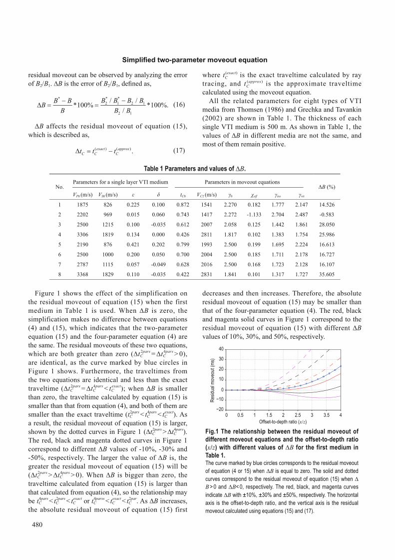
Figure 1 shows the effect of the simplification on the residual moveout of equation (15) when the first medium in Table 1 is used. When ∆B is zero, the simplification makes no difference between equations (4) and (15), which indicates that the two-parameter equation (15) and the four-parameter equation (4) are the same. The residual moveouts of these two equations, which are both greater than zero (∆tC
2pars = ∆tC4pars > 0),
are identical, as the curve marked by blue circles in Figure 1 shows. Furthermore, the traveltimes from the two equations are identical and less than the exact traveltime (∆tC
2pars = ∆tC4pars < tC
exact); when ∆B is smaller than zero, the traveltime calculated by equation (15) is smaller than that from equation (4), and both of them are smaller than the exact traveltime (tC
2pars < tC4pars < tC
exact). As a result, the residual moveout of equation (15) is larger, shown by the dotted curves in Figure 1 (∆tC
2pars > ∆tC4pars).
The red, black and magenta dotted curves in Figure 1 correspond to different ∆B values of -10%, -30% and -50%, respectively. The larger the value of ∆B is, the greater the residual moveout of equation (15) will be (∆tC
2pars > ∆tC4pars > 0). When ∆B is bigger than zero, the
traveltime calculated from equation (15) is larger than that calculated from equation (4), so the relationship may be tC
4pars < tC2pars < tC
exact or tC4parss < tC
exact < tC2par. As ∆B increases,
the absolute residual moveout of equation (15) first
decreases and then increases. Therefore, the absolute residual moveout of equation (15) may be smaller than that of the four-parameter equation (4). The red, black and magenta solid curves in Figure 1 correspond to the residual moveout of equation (15) with different ∆B values of 10%, 30%, and 50%, respectively.
0 0.5 1 1.5 2 2.5 3 3.5 420
10
0
10
20
30
40
Offset-to-depth ratio (x/z)
Resid
ual m
oveo
ut (m
s)
Fig.1 The relationship between the residual moveout of different moveout equations and the offset-to-depth ratio (x/z) with different values of ∆B for the first medium in Table 1. The curve marked by blue circles corresponds to the residual moveout of equation (4 or 15) when ∆B is equal to zero. The solid and dotted curves correspond to the residual moveout of equation (15) when ∆B > 0 and ∆B< 0, respectively. The red, black, and magenta curves indicate ∆B with ±10%, ±30% and ±50%, respectively. The horizontal axis is the offset-to-depth ratio, and the vertical axis is the residual moveout calculated using equations (15) and (17).
Table 1 Parameters and values of ∆B.
No.Parameters for a single layer VTI medium Parameters in moveout equations
∆B (%)VP0 (m/s) VS0 (m/s) ε δ tC0 VC2 (m/s) γ0 χeff γiso γvti
1 1875 826 0.225 0.100 0.872 1541 2.270 0.182 1.777 2.147 14.526
2 2202 969 0.015 0.060 0.743 1417 2.272 -1.133 2.704 2.487 -0.583
3 2500 1215 0.100 -0.035 0.612 2007 2.058 0.125 1.442 1.861 28.050
4 3306 1819 0.134 0.000 0.426 2811 1.817 0.102 1.383 1.754 25.986
5 2190 876 0.421 0.202 0.799 1993 2.500 0.199 1.695 2.224 16.613
6 2500 1000 0.200 0.050 0.700 2004 2.500 0.185 1.711 2.178 16.727
7 2787 1115 0.057 -0.049 0.628 2016 2.500 0.168 1.723 2.128 16.107
8 3368 1829 0.110 -0.035 0.422 2831 1.841 0.101 1.317 1.727 35.605

481
Li et al.
To summarize, the residual moveout of equation (15) is affected by the simplification (∆B). If ∆B = 0, the residual moveouts of the two equations (4) and (15) are identical. If ∆B < 0, the larger |∆B| is, the bigger the residual moveout of equation (15) will be, and it will be larger than that for the four-parameter equation (4). If ∆B > 0, as ∆B increases, the residual moveout of equation (15) fi rst decreases and then increases, and therefore the residual moveout of equation (15) may be smaller than that of equation (4).
(2) Single-layer VTI mediaNext, the applicability of different C-wave moveout
equations are compared in three kinds of single-layer VTI media: media 1, 2, and 3 in Table 1. In Figure 2a, ∆B is bigger than zero, and the applicability of equation (15, black curves) is up to x/z = 3.0, which is higher than that of the hyperbolic equation (red curves), equation (1, green curves) and slightly higher than the four-parameter
equation (4, blue curves). In Figure 2b, |∆B| is small, and the applicability of equation (15) and that of the four-parameter equation (4) is almost the same, which is higher than that of equation (1) and the hyperbolic equation. In Figure 2c, ∆B is bigger than zero, the applicability of different moveout equations is the same as for Figure 2a, and the applicability of equation (15, black curves) is about x/z = 3.0.
Figure 2 shows that, although the two-parameter equation (15) is simplified, it still retains high applicability in most media because ∆B > 0 in most media; the valid offset-to-depth ratio can be up to 3.0 (x/z ≤ 3.0), except in medium 2 where σ or η is negative. Tsvankin (2001) described its complexity. The residual moveouts of all the equations increase when the offset-to-depth ratio increases, since the high-order terms are ignored in the Taylor series expansion. The applicability can be further improved by adding higher order terms.
Resid
ual m
oveo
ut (m
s)
0 0.5 1 1.5 2 2.5 3 3.5 420
10
0
10
20
30
40
Offset-to-depth ratio (x/z)
20
10
0
10
20
30
40(a) (b) (c)
Resid
ual m
oveo
ut (m
s)
0 0.5 1 1.5 2 2.5 3 3.5 4Offset-to-depth ratio (x/z)
0 0.5 1 1.5 2 2.5 3 3.5 440
30
20
10
0
10
20
Offset-to-depth ratio (x/z)
Resid
ual m
oveo
ut (m
s)
(3) Layered VTI mediaFinally, the applicability of equation (15) in a three-
layer VTI model is checked. The fi rst, second and third layers are media 1, 2, and 3 of Table 1, respectively. The root-mean-squared (RMS) parameters used in different equations are shown in Table 2. Figures 3a, 3b, 3c and 3d show the applicability of the two-parameter C-wave moveout equation (15), the hyperbolic C-wave moveout equation, the isotropic two-parameter C-wave moveout
Fig.2 The relationship between the residual moveout of different moveout equations and the offset-to-depth ratio in a single-layer VTI medium.
Pannels (a) – (c) correspond to materials 1, 2, and 3 in Table 1, respectively. The four approximate C-wave moveout equations are: black crosses—the two-parameter equation (15), red squares—the hyperbolic equation, green triangles—the two-parameter equation (1), and blue circles—the original four-parameter equation (4). The axis notation is the same as in Figure 1.
equation (1) and the four-parameter C-wave moveout equation (4). The red crosses, the blue circles and the black squares indicate the residual moveout for the fi rst, second and third refl ection interfaces, respectively. Figure 3 shows that the applicability of the two-parameter C-wave moveout, equation (15), is slightly lower than that of the four-parameter C-wave moveout, equation (4), and the valid offset-to-depth ratio is about 2.0 (x/z ≤ 2.0), which is better than that from equation (1,
(a)
Resid
ual m
oveo
ut (m
s)
3 3 4Offset-to-depth ratio (x/z)
Resid
ual m
oveo
ut (m
s)
22 2 3 3 4
Offset-to-depth ratio (x/z)
(b)

482
Simplifi ed two-parameter moveout equation
Based on equation (15), a double-scanning semblance analysis can be designed to obtain VC2 and γvti from C-wave data alone, for a given event with fi xed tC0. The results are shown in Figures 4b, 4c, and 4d for the three events in Figure 4a. VC2 and γvti can be estimated by picking the central values. The picked values and errors are shown in Table 3. The double-scanning semblance analysis shows good resolution and suffi cient accuracy for resolving VC2 and γvti. Errors for VC2 are less than 0.5% for all events, and errors for γvti are about 8.6% for the bottom events and less than 2% for the other two events.
Resid
ual m
oveo
ut (m
s)
3 3 4Offset-to-depth ratio (x/z)
(c)
Resid
ual m
oveo
ut (m
s)
3 3 4Offset-to-depth ratio (x/z)
(d)
x/z ≤ 1.5) and the hyperbolic C-wave moveout equation (x/z ≤ 1.0). Therefore, when a two-parameter equation is used, γvti is more suitable to describe the C-wave moveout than γiso.
Table 2 Root-mean-squared (RMS) parameters for the three-layer VTI media based on materials 1, 2 and 3 in Table 1
No. Zi (m) tC0 (s) VC2 (m/s) γ0 γeff χeff γiso γvti
1 500 0.872 1541 2.270 1.190 0.182 1.777 2.147
2 500 1.615 1485 2.271 1.958 0.141 2.165 2.261
3 500 2.227 1645 2.210 1.405 0.215 1.875 2.137
Double scanning Figure 4a shows the synthetic C-wave gather
calculated using ray tracing, which is based on the three-layer model shown in Table 2. The thickness of each layer is 500 m, the trace interval is 25 m, and a 25 Hz Ricker wavelet is used. The change of amplitudes is not considered, when amplitudes are normalized. The data are muted when x/z ≤ 3.0.
0
0.5
1.0
1.5
2.0
2.5
3.0
3.5
4.0
Time (
s)
0 1000 2000 3000 4000Offset (m)
Fig.3 The relationship between the residual moveout of different C-wave moveout equations and the offset-to-depth ratio in a three-layer VTI media model in Table 2.
(a) equation (15), (b) the hyperbolic C-wave moveout equation, (c) equation (1), and (d) the four-parameter C-wave moveout equation (4). The line styles are: red crosses indicate the fi rst layer, blue circles the second layer and black squares the third layer. The axis notation is the same as in Figure 1.
(a) (b) tC0 = 0.87 s
VC2 (m/s)
vti
1400 1440 1480 1520 1560 1600 1640 16801.61.71.81.9
22.12.22.32.42.52.6
Table 3 The values and errors of VC2 and γvti obtained from the double-scanning using equation (15)
No.Exact value Values from
double-scanning Error
VC2 (m/s) γvti VC2 (m/s) γvti ∆VC2 (%) ∆γvti (%)
1 1541 2.147 1545 2.19 0.2 22 1485 2.261 1487 2.22 0.13 1.83 1645 2.137 1650 2.32 0.3 8.6
483
Li et al.
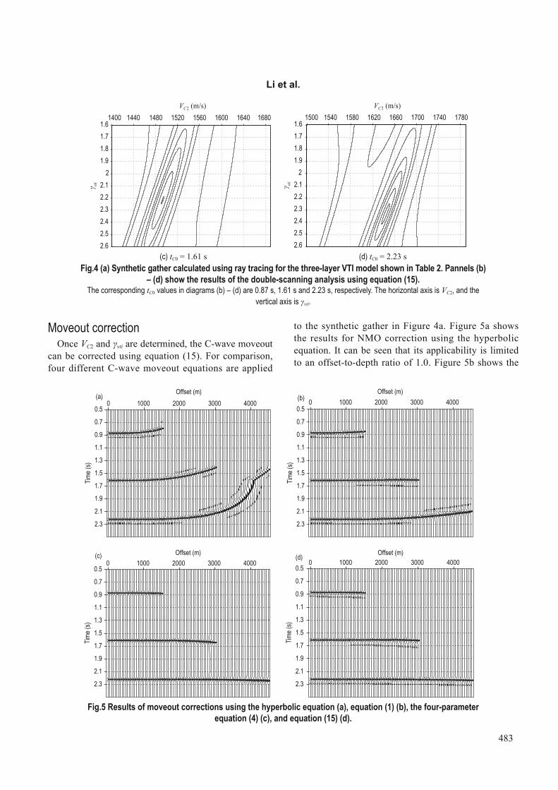
to the synthetic gather in Figure 4a. Figure 5a shows the results for NMO correction using the hyperbolic equation. It can be seen that its applicability is limited to an offset-to-depth ratio of 1.0. Figure 5b shows the
(c) tC0 = 1.61 s (d) tC0 = 2.23 sFig.4 (a) Synthetic gather calculated using ray tracing for the three-layer VTI model shown in Table 2. Pannels (b)
– (d) show the results of the double-scanning analysis using equation (15). The corresponding tC0 values in diagrams (b) – (d) are 0.87 s, 1.61 s and 2.23 s, respectively. The horizontal axis is VC2, and the
vertical axis is γvti.
1400 1440 1480 1520 1560 1600 1640 16801.61.71.81.9
22.12.22.32.42.52.6
VC2 (m/s)vti
1500 1540 1580 1620 1660 1700 1740 17801.61.71.81.9
22.12.22.32.42.52.6
VC2 (m/s)
vti
Moveout correctionOnce VC2 and γvti are determined, the C-wave moveout
can be corrected using equation (15). For comparison, four different C-wave moveout equations are applied
0.5
0.7
0.9
1.1
1.3
1.5
1.7
1.9
2.1
2.3
Time (
s)
0 1000 2000 3000 4000Offset (m)(a)
0.5
0.7
0.9
1.1
1.3
1.5
1.7
1.9
2.1
2.3
Time (
s)
0 1000 2000 3000 4000Offset (m)
(b)
0.5
0.7
0.9
1.1
1.3
1.5
1.7
1.9
2.1
2.3
Time (
s)
0 1000 2000 3000 4000Offset (m)(c)
0.5(d)
0.7
0.9
1.1
1.3
1.5
1.7
1.9
2.1
2.3
Time (
s)
0 1000 2000 3000 4000Offset (m)
Fig.5 Results of moveout corrections using the hyperbolic equation (a), equation (1) (b), the four-parameter equation (4) (c), and equation (15) (d).

484
Simplifi ed two-parameter moveout equation
results of the two-parameter equation (1), which is valid for an offset-to-depth ratio of 1.5. Figure 5c shows the results of the four-parameter equation (4), which is valid for an offset-to-depth ratio of 2.0. Figure 5d shows that the two-parameter equation (15) is accurate for the offset-to-depth ratio 2.0. Therefore, the two-parameter equation (15) can be used for moveout correction when the offset-to-depth ratio is less than 2.0.
Field data example
A land C-wave dataset from the Sanhu area of Western China is used to illustrate the application of equations (1) and (15). Figure 6a shows a common converted point gather (CCP). Figure 6b shows the results of hyperbolic processing, ignoring the effect of the asymmetric raypath and anisotropy. There is significant stretching in the red rectangular area, where a heavy mute is required, and only events at the near offset are flattened. Figure 6c shows the results of equation (1) considering the asymmetric path but ignoring the anisotropy. There are fewer stretched events, and the valid offset ranges are increased, but the events at far offset are still not flattened, such as the events within the red rectangular area. The results of equation (15), accounting for both the asymmetric path and anisotropy, are shown in Figure
6d. The events shown in the red rectangular area are flattened even in the far offset. Thus, we can conclude that equation (15) can be applied to C-wave data, and γvti is more suitable than γiso in anisotropic media.
Discussion
The above analysis shows that the C-wave moveout in VTI media can be described by two parameters: VC2 and γvti, and the two parameters can be determined using C-waves alone when the offset-to-depth ratio is up to x/z = 2.0. However, γiso cannot be obtained from C-wave data in VTI media, because its corresponding equation (1) is only valid for x/z ≤ 1.5 in VTI media, and within this range, scanning for γiso gives no resolution. Therefore, the parameters that can be recovered from C-wave moveout alone in VTI media are VC2 and γvti, but not γiso. This has important implications for parameter estimation and subsequent data processing. When equation (15) is used in data processing, an initial common converted point gather (CCP) should be fi xed, and then double-scanning completed in some time window. Finally, normal moveout correction should be done using the results from double-scanning. An appropriate length of time window should be given: usually it is about 1.5–2 times longer than the main period. Anisotropic parameters and
(a) Input CCP gather. (b) Hyperbolic moveout correction.
0 500 1000 1500 2000 2500
Offset (m)
0
0.5
1.0
1.5
2.0
2.5
Time (
s)
0 500 1000 1500 2000 2500
Offset (m)
0
0.5
1.0
1.5
2.0
2.5
Time (
s)

485
Li et al.
matching between P- and C-wave data are interrelated in the application of multi-component data. Equation (15) can be also used for event matching between P- and C-wave data. Let us consider the following three cases:
1. Known anisotropy and unknown correlation (i.e. γ0 is unknown). If the effects of anisotropy are negligible, or ηeff can be estimated from elsewhere, γiso can be estimated from γvti, ηeff: γiso = γvti/(1 + 2ηeff). γiso can then be used to complete the correlation analysis for γ0.
2. Known correlation (γ0) and γeff, and unknown anisotropy. This is a more likely case. A coarse correlation between the P-wave and C-wave data is often possible for the purpose of determining γ0. In the meantime γeff may be estimated from the conversion-point signature (Yuan et al., 2002), and γiso can be obtained using equation (2). This leads to an estimate of ηeff using
1 ( 1).2
vtieff
iso
(18)
3. Known correlation (γ0) and VC2, and unknown anisotropy. This is another likely case. If there are good VP2 data, and a coarse correlation is possible for determination of γ0, then the anisotropic parameter ηeff can be estimated by,
2 2
22 22 2
1 1( 1) ( 1).2 2
Ph C vtieff
P P
V VV V
(19)
Equation (19) offers an alternative way to quantify ηeff from P-wave and C-wave data, and this method is expected to be more reliable in comparison with ηeff estimated by other methods, since VC2, VP2, γvti can all be estimated relatively robustly.
Conclusions
The new equation (15) for layered VTI media has the same form as equation (1) for layered isotropic media. Only two parameters (VC2 and γvti) are needed in the new equation, and the number of parameters is less than other C-wave moveout equations, but the applicability is sufficient for processing. This simplifies the procedure for parameter estimation and C-wave processing, and has the potential to evolve into a useful approach.
In layered VTI media, a new velocity ratio γvti is introduced, which is the squared velocity ratio between the P-wave horizontal velocity and the C-wave stacking velocity. The new two-parameter C-wave moveout equation (15) for VTI media can be derived when the
(c) Non-hyperbolic moveout correction using equation (1). (d) Non-hyperbolic moveout correction using equation (15).Fig.6 The C-wave moveout correction in land data.
0 500 1000 1500 2000 2500
Offset (m)
0
0.5
1.0
1.5
2.0
2.5
Time (
s)
0 500 1000 1500 2000 2500
Offset (m)
0
0.5
1.0
1.5
2.0
2.5
Time (
s)

486
Simplifi ed two-parameter moveout equation
heuristic expression of ηeff and χeff is used. Equation (15) is accurate when x/z ≤ 3.0 in a single VTI medium, except in medium 2 in Table 1, where the applicability is reduced to x/z = 2.0. In layered VTI media, equation (15) is valid for x/z ≤ 2.0. The two parameters can be determined directly by double-scanning without initialization and iteration. However, anisotropic parameters cannot be recovered from C-wave data alone; they should be combined with P-wave data.
To conclude, the new two-parameter C-wave moveout equation can describe the C-wave moveout for intermediate values of offset-depth ratio. γiso quantifies the effects of the asymmetric ray path, and γvti quantifi es both the asymmetric ray path and the anisotropy. In a single-layer VTI medium, γvti = γiso(1+ 2η). The two-parameter C-wave moveout equation reduces the number of parameters, simplifies the procedure for parameter estimation and C-wave processing, and also provides parameters that can be used for matching between P- and C-wave data. We demonstrate the application of the two-parameter C-wave moveout equation in both synthetic data and fi eld data, and obtain good results.
Acknowledgements
The authors express their sincere thanks to the anonymous reviewers, whose critical and constructive comments and suggestions greatly improved the fi nal paper.
References
Alkhalifah, T., and Tsvankin, I., 1995, Velocity analysis for transversely isotropic media: Geophysics, 60, 1550 – 1566.
Cheret, T., Bale, R., and Leaney, S., 2000, Parameterization of polar anisotropic moveout for converted waves: 70th Ann. Internat. Mtg., Soc. Explor. Geophys., Expanded Abstracts, 1181 – 1184.
Dai, H. C., and Li, X. Y., 2010, A revised two-parameter moveout equation of PS converted-waves in VTI media: 80th Ann. Internat. Mtg., Soc. Explor. Geophys., Expanded Abstracts, 248 – 252.
Fowler P. J., 2003, Practical VTI approximations: a systematic anatomy. Journal of Applied Geophysics,
54(3), 347 – 367.Grechka, V., and Tsvankin, I., 2002. The joint non-
hyperbolic moveout inversion of PP and PS data in VTI media: Geophysics, 64, 668 – 677.
Hake, H., Helbig K., and Mesdag C. S., 1984, Three-term Taylor series for t2-x2 -curves of P- and S-waves over layered transversely isotropic ground: Geophysical Prospecting, 32(5), 828 – 850.
Li, X. Y., 2003, Converted-wave moveout analysis revisited: The search for a standard approach: 73rd Ann. Internat. Mtg., Soc. Expl. Geophys., 805 – 808.
Li, X. Y., and Yuan, J., 2001, Accuracy and sensitivity analysis for estimating anisotropic parameter from 4C seismic data, 71st Ann. Internat. Mtg., Soc. Explor. Geophys., Expanded Abstracts, 869 – 872.
Li, X. Y., and Yuan, J., 2003, Converted-wave moveout and conversion-point equations in layered VTI media revisited: Theory and applications, Journal of Applied Geophysics, 54, 297 – 318.
Li, X. Y., and Zhang, Y., 2011, Seismic reservoir characterization: how can multicomponent data help?: Journal of Geophysics and Engineering, 8, 123 – 141.
Stovas, A., 2010, Generalized moveout approximation for qP- and qSV-waves in a homogeneous transversely isotropic medium: Geophysics, 75(6), 79 – 84.
Stovas, A., and Ursin, B., 2004, New travel-time approximations for a transversely isotropic medium: Journal of Geophysics and Engineering, 1(2), 128 – 133.
Tessmer, G., and Behle, A., 1988, Common reflection point data-stacking technique for converted waves: Geophysical Prospecting, 36(7), 671 – 688.
Thomsen, L., 1986, Weak elastic anisotropy: Geophysics, 51, 1954 – 1966.
Thomsen, L., 1999, Converted-wave refl ection seismology over inhomogeneous anisotropic media: Geophysics, 64(3), 678 – 690.
Tsvankin, I., and Thomsen, L., 1994, Nonhyperbolic reflection moveout in anisotropic media: Geophysics, 59(8), 1290 – 1304.
Tsvankin, I., 2001, Seismic Signatures and Analysis of Reaction Data in Anisotropic Media: Elsevier.
Yuan, J., 2002, Analysis of four-component seafl oor seismic data for seismic anisotropy: Ph.D. thesis, The University of Edinburgh.
Yuan, J., Li, X. Y., and Zhu, X., 2002, C-wave anisotropic parameter estimation from conversion point: 64th Annual Meeting, EAGE, Expanded Abstracts, 253 – 256.

487
Li et al.
Appendix A
Throughout the paper, the notations of Thomsen (1999) and Li and Yuan (2003) are used. As shown in Figure 7, we consider an n-layer VTI medium, and a P-SV wave converted at the bottom of the n-th layer with a down-going P-wave leg and up-going SV-wave leg. The subscripts P, S, and C denote P-, S-, and C-waves, respectively. The subscript i denotes interval quantities, the subscript 2 denotes root-mean-squared (RMS) quantities, and the subscript 0 denotes vertical or average quantities where appropriate. t stands for travel time, V for velocity, and γ for velocity ratio. Thus, tP0, tS0 and tC0 stand for the vertical travel times for P-, S- and C-waves, respectively; VP0, VS0 and VC0 stand for the vertical or average velocities for the three waves, respectively; VP2, VS2 and VC2 stand for the stacking (RMS) velocities; and γ0, γ2 and γeff represent the vertical, stacking (RMS) and effective velocity ratio.
Introduce three more anisotropic parameters ηi, ζi and χi, satisfying,
2 2 20 0
( ) 2(1 ),
(1+2 ) 1 /i i i
ii S i P iV V
(A-6)
2 2 2
0 0
2(1 ),
(1+2 ) 1 /i i
ii S i P iV V
(A-7)
20 ,i i effi i (A-8)
where,
20 ( ).i i i (A-9)
η i controls the anisotropic behavior in long-spread P-wave reflection moveout (Alkhalifah and Tsvankin, 1995), ζi controls the anisotropic behavior in intermediate-spread S-wave moveout (Tsvankin and Thomsen, 1994), and χi controls the long-spread C-wave refl ection moveout (Li and Yuan, 2001).
For n-layers, ηeff and ζeff as effective anisotropic parameters are related to the interval quantities by,
4 42 0 0 24
10 2
1 (1 8 ) ,8
N
eff p i p i i P PiP P
V t t Vt V
(A-10)
4 40 2 2 04
10 2
1 (1 8 ) ,8
N
eff S S S i S i iiS S
t V V tt V
(A-11)
2
0 .eff eff eff eff (A-12)
ηeff is the effective anisotropic parameter for P-waves in multi-layered media (Alkhalifah and Tsvankin, 1995). ζeff and χeff are the corresponding parameters for SV-waves and C-waves in layered VTI media, respectively. For a single-layer VTI medium, ηeff, ζeff and χeff will be reduced to ηi, ζi and χi, respectively, as shown in equations (A-6), (A-7) and (A-8).
Li Xiao-Ming is a Ph.D. student at the China University of Petroleum (Beijing). She graduated from the same university with a Bachelor’s degree in 2007. She is mainly engaged in the study of multi-component data processing and seismic anisotropy.
xxp xs ReceiverSource
p sP SV
Fig.7 Geometry of a converted-wave raypath in horizontally layered transversely isotropic media with a vertical symmetry axis (VTI). For an n-layer VTI medium, the corresponding interval parameters for the i-th layer (i = 1, 2, …, n ) are VP0i, VS0i, VP2i, VS2i the vertical one-way travel times are ∆tP0i, ∆tS0i respectively, and the Thomsen (1986) parameters are εi and δi.
The interval parameters and RMS quantities have the following relationships,
2
0 2 20 2
0 2 0
, , ,P i P i ii i effi
S i S i i
V VV V
(A-1)
0 0 0 0 0 0 01 1
,, ,n n
P P i S S i C P Si i
t t t t t t t (A-2)
2 2 2 22 2 0 2 2 0
1 10 0
1 1, ,n n
P P i P i S S i S ii iP S
V V t V V tt t
(A-3)
2 2 20 2 0 2 0 2 ,C C P P S St V t V t V (A-4)
2
0 2 20 2
0 2 0
, , .S Peff
P S
t Vt V
(A-5)